Compared to the other three GNSS constellations, what is currently the greatest strength of GPS? What is its greatest weakness?
Bernard Gruber
“I would submit that the greatest strength of GPS is its ubiquity. GPS really is everywhere — worldwide and accepted. It is a trusted and free continuous source, backed by the integrity of the United States, and used for location, navigation, tracking, mapping and timing in myriad applications. Spawned and integrated applications that rely on GPS are well into the high billions of dollars! As they say, ‘When you’re on top, people will be gunning for you.’ In the case of GPS, I would offer that that is its greatest weakness — overreliance without a backup for those users that should have one.”
— Bernard Gruber, Northrop Grumman
Jules McNeff
“I’ll second Bernie’s comments and add that the nearly universal trust in GPS, despite the protestations that it is operated by the military, is a result of decades of openness regarding its operation and improvement. Rare faults are acknowledged and repaired, and planned civil modernizations, though sometimes delayed, are developed with civil collaboration and are fully and publicly documented. Its success and consistency have made it a target, which would be a significant weakness but for a growing awareness of the need for complementary PNT sources to sustain the value it has created.”
— Jules McNeff, Overlook Systems Technologies
F. Michael Swiek
“On strengths, it is very simple: reliability, consistency, stability and transparency.”
By Alex Damato, Acting Executive Director, GPS Innovation Alliance
Alex Damato
It can be easy to take GPS for granted as the average driver and smartphone user continues to enjoy convenience, entertainment and navigation from this technology, enhancing nearly every part of our daily lives. While we may not enjoy its benefits every day, one important use case keeps us and our environment safer: GPS has become a vital part of modern emergency response.
Many Americans across the nation are preparing for the impending hurricane season or the threat of other natural disasters, such as wildfires and earthquakes. GPS will play a critical role in recovery and response efforts. When natural disasters occur, accurate and actionable location information helps save lives and restore critical infrastructure as quickly as possible.
GPS has fundamentally improved access to information that can help the public prepare for these natural disasters, rather than waiting for them to strike. This information is more critical than ever. For example, California’s Oak fire spread to almost 20,000 acres and is part of a larger trend in California that has destroyed 14,700 buildings and killed 36 people over the past two years. Farther north, 530 wildfires in Alaska burned areas larger than the state of Connecticut in the state’s worst fire season in recent history.
In addition to helping the public face natural disasters, GPS helps firefighters plan their operations more efficiently and enables them to receive real-time information on the location of the wildfires they are fighting. With real-time mapping, planning and operations, fire chiefs can respond immediately to areas where wildfires are dangerously advancing.
In turn, GPS protects our first responders by preventing firefighters from getting caught in unpredictable fires they would have otherwise not known were heading their way.
Firefighters use IGNIS drones to help prevent wildfires from starting or safely contain them with backburns. IGNIS relies on GPS for tracking, safety and control, which in turn helps firefighters avoid the dangers associated with being near prescribed burns. Without GPS, resources to help firefighters would not be deployed as efficiently — wildfires could spread even more quickly as a result, causing even more damage to our homes and infrastructure.
Beyond wildfires, GPS technology is critical to emergency response and weather safety. GPS data allow emergency responders to better locate callers and reduce the incidence of misrouting to outside jurisdictions. Using GPS data, a caller can be located in close proximity to his or her actual location. By reducing rates of misrouting and accurately pinpointing emergency locations, GPS helps reduce response time by taking away the need to reroute calls and search for callers’ locations.
In a recent experiment, NASA-commissioned researchers used GPS signals to better predict a hurricane’s maximum wind speed, which could help federal agencies and forecasters better predict the danger of hurricanes and provide more actionable information to determine whether to issue evacuation orders.
The GPS Innovation Alliance (GPSIA) is proud to support the role of GPS as a critical enabling technology for public safety, disaster response and relief efforts. With GPS, precise real-time location information is at the fingertips of both consumers and first responders from pre-disaster planning efforts to post-disaster recovery. While GPS has already fundamentally improved modern emergency response systems, GPSIA will continue to advocate for the continued growth of these lifesaving GPS-enabled technologies and applications through rigorously developed technical rules, interference protections, and a predictable spectrum environment.
Many of us have grown accustomed to the ease of GPS-enabled technologies, from smartphone to fitness trackers. At GPSIA, we’re also particularly proud of the role GPS plays in the many other life-saving ways the technology is being used and are committed to continuing this critical work.
“Nothing can remain immense if it can be measured,” Hannah Arendt wrote in 1958 in The Human Condition. This could be the guiding inspiration for any geodesist or surveyor throughout history. In about 240 B.C., Eratosthenes became the father of geodesy by ingeniously measuring Earth’s circumference using the Sun, a well, a vertical column, the distance a camel caravan traveled from Syene to Alexandria and some basic mathematics. His estimate of 46,000 kilometers was 16% too large but remarkably close considering that he lacked any modern measuring tool. (For a great account of this epic feat, see John Noble Wilford’s The Mapmakers.)
Geodesy, a branch of applied mathematics, is concerned with accurately measuring and understanding three of Earth’s fundamental properties: its geometric shape, its orientation in space, and its gravity field. Earth’s true shape varies from the mathematically smooth surface of an ellipsoid due to local differences in its density that cause variations in the strength of the gravitational pull, in turn causing regions to dip below or bulge above a reference ellipsoid.
This undulating shape is the geoid, which geodesists have defined as the three-dimensional surface along which the pull of gravity is a specific constant. It serves as the zero-level surface for height measurements globally, and all GNSS are pegged to it. It is a hypothetical surface that essentially represents an extension of the idealized mean sea level over (actually, mostly under) Earth’s land surface. Unlike the surface of the oceans, however, it is unaffected by wind, waves, the Moon, or forces other than Earth’s gravity.
Surveyors are content with measuring much smaller portions of Earth’s surface, from single lots to national boundaries. Unlike Eratosthenes, they work with the latest fruit of modern science and technology — including GNSS receivers, robotic total stations, inertial measurement units, lidar, other sensors and unmanned aerial vehicles — and can measure distances with millimeter precision.
When I started in this business a little more than 20 years ago, we used to group GPS receivers by accuracy into three buckets: consumer grade, resource/mapping grade and survey grade. As accuracy has increased for all GNSS receivers, the boundaries between those categories, especially between mapping and surveying, have blurred. Additionally, we now have way more GNSS satellites — in some parts of the world, as many as 70 are in view at one time — and a panoply of public and private, ground-based and satellite-based corrections services.
So, surveyors have a growing set of tools, and they are constantly getting more accurate and more user-friendly.
Now, let me throw another number in the mix: 66. That is the average age of surveyors in the United States. In the short run, employment for surveyors hinges in part on the vagaries of the economy. In the long run, however, population growth and climate change will force large investments in infrastructure. On most construction sites, the first to arrive and the last to leave are the surveyors. We know what their tools are, but who will they be?
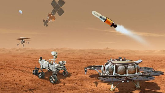
NASA and the European Space Agency (ESA) have been cooking up a way to get some of Mars back to Earth, so that samples can be analyzed in detail — just like the rocks the astronauts brought back during the Apollo missions, which gave us a deeper understanding of our Moon.
The Perseverance rover already on Mars has been seeking promising areas to investigate that might provide evidence of ancient past life, with the help of the Ingenuity helicopter drone. Recently, the two worked together to drive the rover to an old river delta, expected to be a prime location where such samples could be found.
The rover has been drilling and saving rock and dirt samples in onboard storage tubes. The difficulty is that getting them back to Earth requires another major undertaking.
Returning the Samples
Termed the “Sample Return Mission,” the two space agencies have been discussing for months how best to bring the samples back, and have now refined an approach. Given that Perseverance has been so good at the job it was given, the NASA/ESA team has decided that the rover should be used for the return mission in 2030 when things would be in operation on Mars. (We’re not sure if the warranty sticker on Perseverance will still be valid in 2030, but if past performance is an indication, all the rovers have significantly outlived their initial design lives.)
Its partner Ingenuity has graduated from proving it can fly in the thin Martian air to actually scouting routes for the large rover. Because Ingenuity has proven reliable and capable of traveling significant distances, NASA and ESA have decided that two new helicopter drones will become part of the return mission. They will be based on the successful Ingenuity design, but will be fitted with wheels, one on each of the four landing legs, to enable movement on the ground.
They will also be fitted with a device which is capable of picking up and carrying a sample tube. Since the prototype drone helicopter was designed to be as light as possible, this infers a substantial increase in lift capacity will be required. The original mission included a sample-collection rover, but this task will now be assigned to Perseverance, with the two sample-carrying helicopters acting as backup, if needed.
An earlier concept had the rover dropping sample canisters behind it as it progressed around the surface for subsequent pick up. This concept appears to have been shelved for the moment. Keeping the canisters onboard the rover throughout perhaps simplifies transfer to the return lander.
This NASA return sample concept illustration includes wheeled helicopters. (Image: NASA/JPL-Caltech)
The Mars Ascent Vehicle would then carry the samples into orbit, to a waiting Earth Return Obiter, where the samples would be transferred to a return system for onward transit and atmospheric re-entry to Earth. Some of these details are a little sketchy, but there sure are a lot of moving (autonomous, robotic?) parts. This, of course, means a lot of opportunities for something to go wrong. No doubt continuing refinement of the mission will reduce the risks. The Jet Propulsion Lab (JPL) and AeroVironment designed and built Ingenuity — they may face some challenges developing the successor helicopter drones.
Meanwhile, Here on Earth…
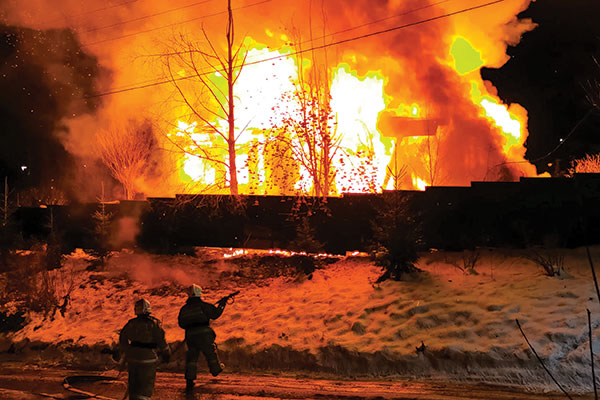
Drones led the news Aug. 1, when President Biden announced the killing of Ayman al-Zawahiri in Kabul, Afghanistan. Al-Zawahiri topped the U.S. 9/11 wanted list, and his removal was all about the offensive use of drones. Presumably fired from a General Atomics Reaper variant drone at quite some altitude, two Hellfire AGM-114R9X “knife bomb”missiles took out al-Zawahiri as he stood alone on the balcony of a home in Kabul.
This means that video/infrared from high altitude was sufficiently clear to determine that the man was alone on the balcony, presumably confirming information on the ground that his family was elsewhere. So long-distance, high-level authorization was then granted to fire on him in a foreign country now run by the Taliban.
Suspected damage at the al-Zawahiri house in Kabul. (Photo: Secunder Kermani/BBC News)
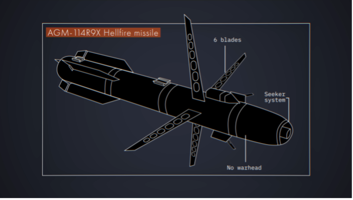
To minimize inadvertent casualties, the Hellfire R9X missile was used, which lacks explosive armaments. The weapon is a nasty piece of work, weighing ~100 lb with an inert payload, and fitted with six long knives that deploy before impact. This missile has previously been used in perhaps 11 other instances to take out terrorist individuals and minimize collateral damage.
Bladed R9X missile lacks a warhead (Image: Newsy/Bellingcat)
This is another instance of how the U.S. use of military drones has become less devastating, but is still very deadly to the specific target.
To Sum Up
We’ve taken a quick glimpse at how NASA and ESA are planning more drones for the surface of Mars, and a much more aggressive use of drones here on Earth.
What role do artificial intelligence (AI) and machine learning (ML) play in analyzing GNSS signals? How might that evolve?
Ellen Hall
“ML is gaining adoption across many GNSS application areas due to its ability to extract data and classify signal information often within complex operational environments. By combining ML with AI, systems are now able to characterize receiver correlator outputs and ranging residuals, and then fuse this with identified environmental features — all potentially increasing GNSS accuracy, integrity and availability. As AI and ML mature, we can expect to see new novel methods to optimize PNT sensor-fusion engines. This will include the combination of GNSS signals with other sensor signals such as inertial and vision.”
— Ellen Hall
Spirent Federal Systems
Bernard Gruber
“AI will come to the battlefield and I would like to think that AI and ML will play a large part in GNSS solutions and specifically protection from adversaries in the future. As AI can ‘anticipate’ threats (i.e., spoofing, jamming, poor coverage) based upon what it sees and knows one should be able to reduce the cycle time to combat that threat (e.g., find/fix/identify and then target, change frequencies, evade). Seeing this data, ML can adapt to morphing threats as well as ‘fuse’ data from all different domains (air, space, sea and land) to provide solutions.”
— Bernard Gruber
Northrop Grumman
Jules McNeff
“I would like to turn the question around and ask ‘How does GNSS contribute to enabling AI and ML to function in physical space?’ Many AI and ML experts don’t think about this aspect of the technologies. Of course, timing is essential to AI and ML operation, but both must be spatially oriented as well if they are to interact effectively with things in the ‘real world.’ The more complex the interactions, the higher the need for precise, continuous PNT information. Depending on the applications, the relationships can become synergistic.”
— Jules McNeff Overlook Systems Technologies
Greg Turetzky
“AI and ML have a great opportunity to fundamentally change the way GNSS signals are used for positioning. In particular, the new modernized signals with wider bandwidths and higher chipping rates create a fundamentally richer data set than classic range/range rate measurements. By analyzing the channel response and using AI/ML techniques, the entire signal environment of LOS and NLOS signals can all be used to make more accurate measurements. In fact, in deep urban canyons with appropriate training, it is even possible to accurately position using only multipath signals such that more multipath makes the position more accurate, not less.”
My previous column highlighted that orthometric heights in NAPGD2022 will be defined through ellipsoid heights and a geoid model, such as GEOID2022. Therefore, changes in the geoid model will be very important to users estimating orthometric heights using GNSS. I briefly described the geophysical reasons for changes in the geoid that affect the orthometric height of a mark.
For the past four years, I have discussed in my columns the tasks associated with the new, modernized 2022 reference frames. It’s now the middle of 2022, so where are the new reference frames? Well, on June 9, Dru Smith, NSRS modernization manager for the National Geodetic Survey (NGS), provided an update on the status of the modernization in a webinar. The Powerpoint slides and video of the presentation can be downloaded from the NGS website under the following title: It’s 2022…Are You Done Yet? I will highlight some of the items from the webinar, but I encourage everyone to download the video and listen to the webinar.
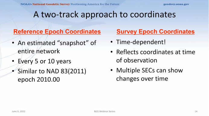
First, Smith mentioned that NGS will be providing new types of coordinates. The NGS denotes this as a two-track approach to coordinates: Reference Epoch Coordinates (REC) and Survey Epoch Coordinates (SEC). See the box below.
New types of coordinates (Image: NGS June 6 webinar)
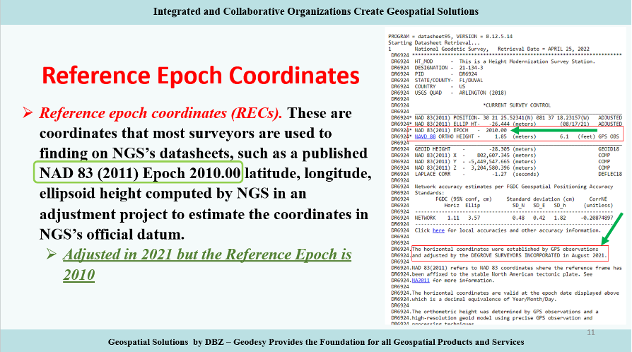
Reference Epochs Coordinates (REC) are defined in NGS Blueprint for the Modernized NSRS, Part 3 as coordinates computed by NGS in an adjustment project to estimate the coordinates at one of the official reference epochs that NGS will define in 2025. RECs are similar to coordinates computed by NGS in a nationwide adjustment project such as the National Adjustment of 2011 (see the box below).
NAD 83 (2011) epoch 2010.00 coordinates (Image: NGS)
NGS has not determined what data will be included in the first iteration of RECs. For the 2020.00 project, the current cutoff date for incorporating data is Dec. 31. Users can submit the data to NGS via OPUS projects and the OPUS-Share tool. To increase the submission of GNSS observations on marks, NGS has developed a beta OPUS-Projects 5.0 webtool that will allow real-time kinematic and real time network (RTK/RTN) observations to be submitted.
As previously mentioned, at this time, the NGS has not determined the cutoff for the earliest data to be included in the determination of the 2020.00 RECs. The agency will be conducting experiments to determine the appropriate cutoff date. These coordinates will require an intra-frame velocity model (IFVM) to generate the RECs at the specific reference epoch.
As of February 2021, based on NGS’ Blueprint for the Modernized NSRS, Part 3, version February 2021, the following is the agency’s policy with regard to RECs:
For a given mark and a given reference epoch, the REC will never be changed–except to correct a blunder.
This does not prevent NGS from adding new RECs
on points with new data that have not yet had an REC computed
for marks that do not have an REC in the most recently passed reference epoch, a new REC can be computed and added to the NSRS.
Survey epoch coordinates (SECs) are defined as coordinates computed by NGS at a specific survey epoch. Users will submit their data and its metadata to NGS, and NGS will then check, adjust and define the coordinates at one “survey epoch.” These coordinates will be “part of the NSRS,” Smith said. NGS is computing coordinates in this manner to provide the best estimate of the coordinates at any mark at a specific moment in time, which is very important in areas influenced by crustal movement.
So, how will NGS process and generate these SECs?
Survey epoch coordinates (SECs) are designed to provide time-dependent geodetic coordinates. Therefore, NGS has to choose some time span in which all observations will be processed together to yield a single SEC of a mark. NGS denotes this time span as a “geometric adjustment window.” NGS wants the adjustment window to be short enough so that movement of a mark did not occur between repeat observations (or was small enough to be ignored) and long enough for users to efficiently and effectively collect redundant observations for submission to NGS (see the box below).
One or more GNSS occupation(s) over a single mark will be processed into one survey epoch coordinate when all occupations take place within one geometric adjustment window.
If a user submits two occupations on one mark, but they happen to fall in two consecutive geometric adjustment windows, NGS will use them to create two distinct survey epoch coordinates. Each SEC will be based on one occupation.
Future columns will provide more explanation about this concept of a geometric adjustment window and how NGS will process the data to generate survey epoch coordinates.
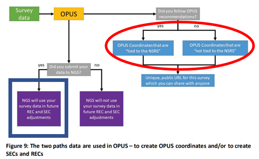
NGS is developing models and tools for users to submit data to NGS to compute coordinates — including OPUS coordinates, reference epoch coordinates and survey epoch coordinates. Figure 9 from Blueprint for the Modernized NSRS, Part 3, version February 2021, is a schematic that shows the flexibility NGS is building into an OPUS-type webtool. Basically, if users follow NGS guidelines and rules, and submit their data to NGS, then NGS will compute and publish REC and SEC coordinates (see the blue outline in the box below). If users only want to compute OPUS coordinates, then they can use NGS’s webtool without submitting the data to NGS (see the red outline in the box below).
Building flexibility into OPUS (Image: NGS)
Dru Smith’s June 9 update on the status of the modernization provided a mockup of how users will be able to retrieve data using their web browsers — a prototype is being developed. The data will also be available in downloadable form such as an XML file for users to input the data and metadata into their programs or databases. I recently discussed some of this material at seminars I presented at the Florida Surveyors and Mapping Society’s 67th annual conference held in Palm Beach Gardens. The participants were very interested in the prototype, but really wanted to learn more about the format and process of the downloadable XML files. I’m sure future NGS webinars will address this topic. I emphasized to the group that they should watch the entire presentation and provide feedback to NGS. As mentioned above, Powerpoint slides and video can be downloaded from the NGS webinar website.
The boxes below highlight a few of the options NGS is considering. The box “Data Delivery – Prototype” is an example provided by Smith during his webinar. It should be noted that the images of the prototype are not included in the downable slides, but they are part of the video. The images presented in this column are screen captures from the video.
Data delivery prototype. (Image: NGS)
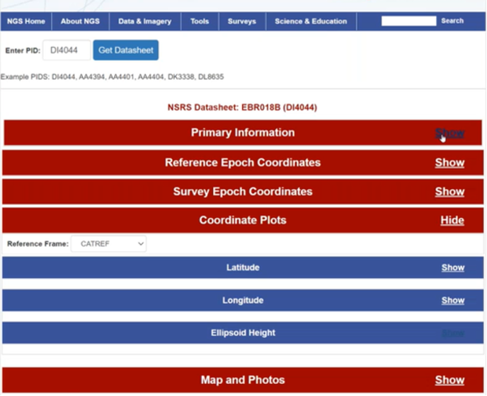
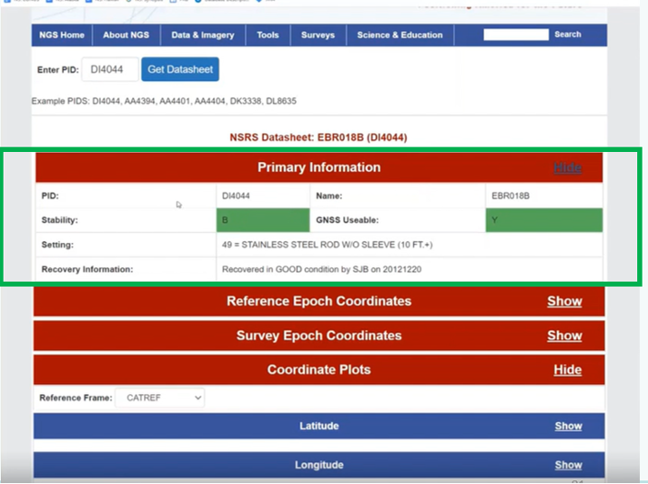
The box below provides some of the basic information of a mark, such as its PID, name, stability, GNSS usable code, setting and the latest recovery information. Again, this is a prototype, so users should feel free to send feedback to NGS. NGS wants to generate a usable product, and is interested in user feedback.
Primary information prototype. (Image: NGS)
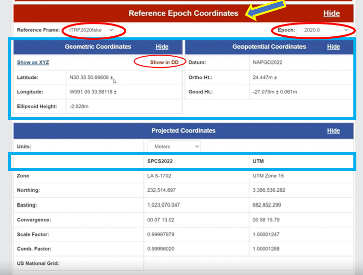
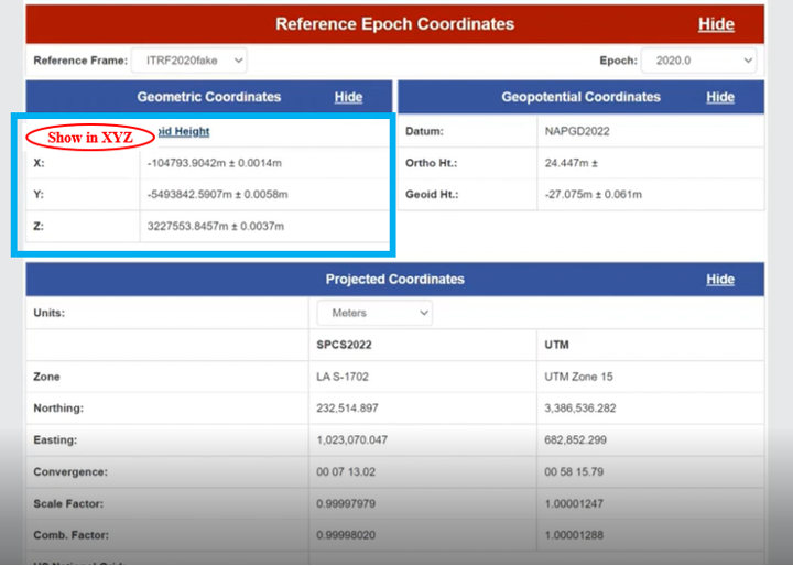
As previously stated, NGS is implementing a two-track approach to coordinates: publishing REC and SEC. The box below provides the REC information of a mark when a user clicks the “Show” button. As shown in the diagram, the reference frame and epoch are provided, as well as the geometric coordinates (latitude, longitude, ellipsoid height) and geopotential coordinate information (NAPGD2022 orthometric height and geoid height).
NGS provides an option for individuals who want the geometric coordinates in the X, Y, Z format (see the box below). Remember, this is only a mockup of a prototype, to give us an idea of the direction NGS is going with its data delivery system in the new, modernized 2022 NSRS.
REC Shown in X,Y,Z. (Image: NGS)
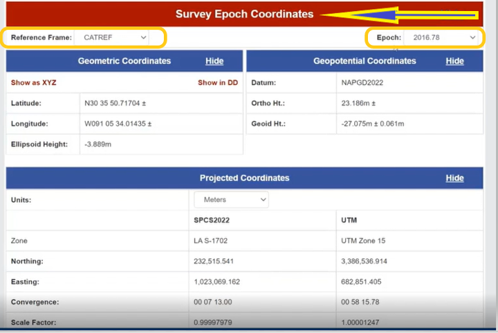
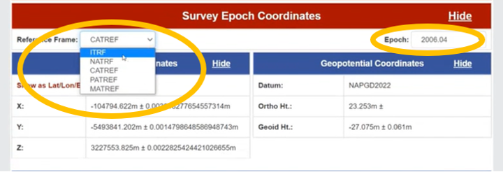
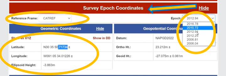
Similar to the REC, the prototype includes SEC. For a mark, the latter are different from the former because SEC are computed at the epoch of the survey observations (see the box below).
The box titled “SEC in CATRF – Prototype” is an example of a mark in the CATRF reference frame and the survey epoch of 2012.94. As indicated in the diagrams, users will be able to select the reference frame (ITRF, NATRF, CATRF, PATRF and MATRF) and the survey epoch.
SEC in CATRF – Prototype
Option to Select Survey EpochOptions to select reference frame (Images: NGS)
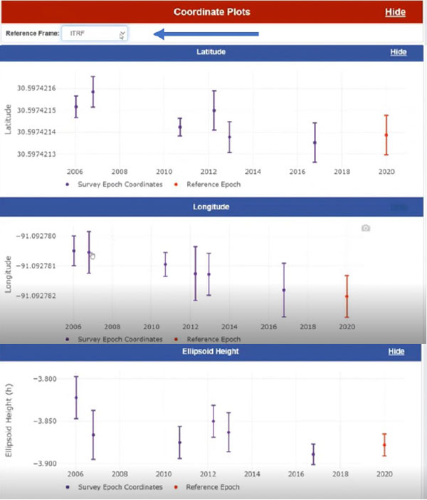
Another feature of the data delivery system is that it provides plots of a mark’s survey epoch coordinate values at different epochs. In the example shown in the box below, the plots provide values of a mark’s latitude, longitude and ellipsoid heights based on each survey epoch data. The user can select various reference frames of the mark to understand the change based on the reference frame.
Coordinate plots in ITRF prototype. (Image: NGS)
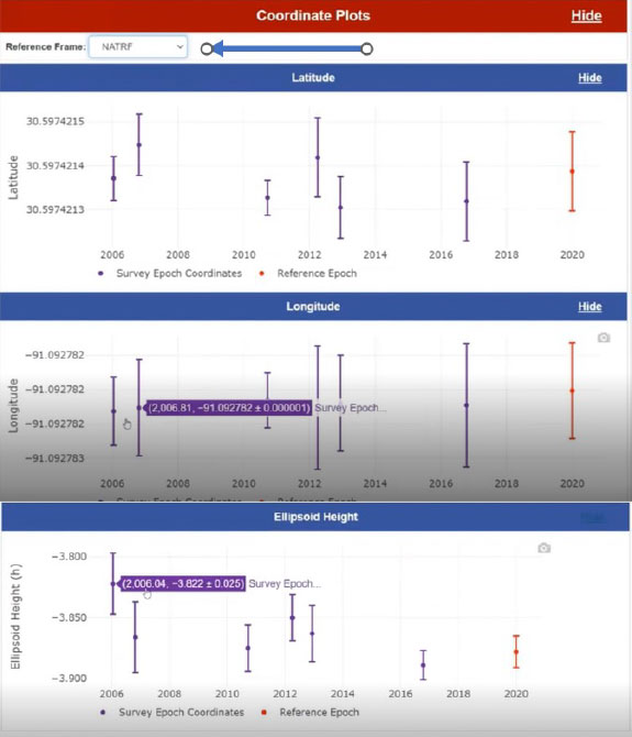
The box below clearly shows a slope in the changes in coordinates based on survey epochs, especially in the longitude. This is the plate rotating in time. You can see the changes in latitude, longitude and ellipsoid height in the NATRF reference frame for the same mark. The latitude and longitude plots do not show a slope because the plate rotation is removed using a model to change from the ITRF reference frame to the NATRF reference frame. That said, the ellipsoid height plots look the same because the rotation model does not change the ellipsoid height.
Coordinate plots in NATRF prototype. (Image: NGS)
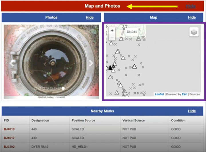
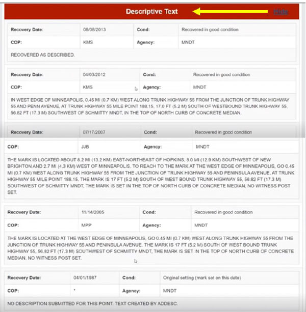
The prototype also provides maps, photos and descriptive text of the mark.
Map and photos of a mark in the prototype. (Image: NGS)Descriptive text prototype (Image: NGS)
Some of this data delivery output may seem familiar to users who have used the NGS beta routines (see the box below).
Beta Routines
Beta routines (Image: NGS)
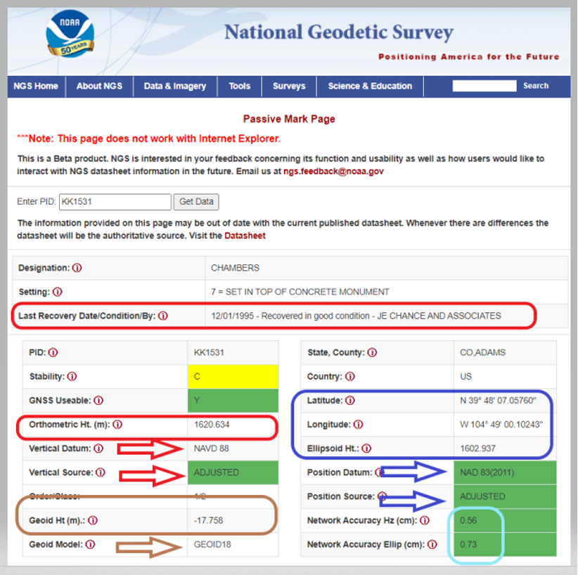
For example, the Passive Mark Page Webtool provides the coordinate information for a mark. My October 2020 column described the tool is detail. See below for an example of the passive mark tool.
Beta Passive Mark of KK1531 (Image: NGS)
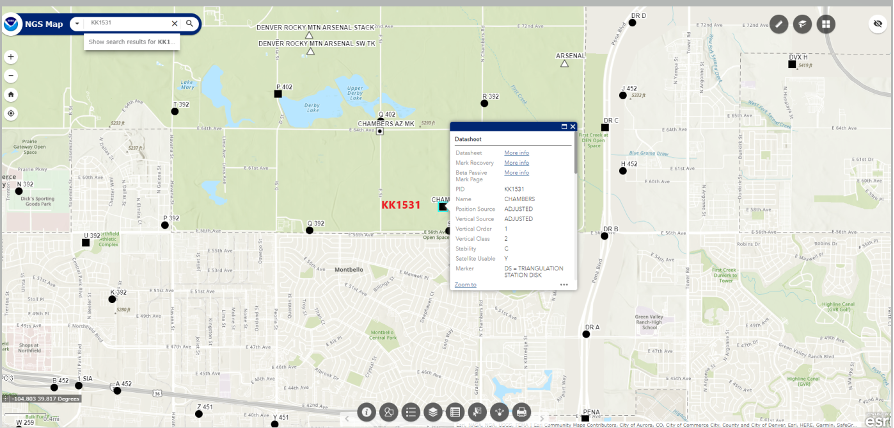
The NGS Beta Map routine enables users to link to NGS datasheets, the passive mark tool and mark recovery, as well as connect to OPUS Shared Solutions and the NOAA CORS Network. See below for an example. It also provides a measuring tool, multiple basemaps and the ability to export data. My December 2021 column described the NGS Beta Map in detail.
Example of NGS Beta Map Routine for KK1531 (Image: National Geodetic Survey)
Only three years remain before the release of the new, modernized NSRS. I encourage everyone to try all of the beta products, and download Dru Smith’s June 6 webinar for a better understanding of the agency’s current thoughts on how it will provide data to users in the new, modernized NSRS. As for all the NGS beta products, the agency would like users to try the tools and provide feedback on what they liked and what they didn’t like, as well as any additional information you need or would like to see. The NGS is trying to develop tools useful to everyone, but that won’t be possible unless they hear from users.
The following statement on NGS beta products explains how to provide feedback and why it is important:
“This is a beta product. NGS is interested in your feedback concerning its function and usability as well as how users would like to interact with NGS datasheet information in the future. Email us at [email protected].”
What improvements will the Next Generation Operational Control System (OCX) bring?
Ellen Hall
“The OCX system is a part of an enormous modernization effort to enhance the ground control segment of the current GPS. This enhancement alone increases accuracy, but coupled with modernized satellites, the next generation OCX will increase and improve coverage and security of GPS. In terms of coverage, the Next Generation OCX will be able to fly twice as many satellites, including both legacy equipment as well as GPS IIIF satellites. In terms of security, the modernized receivers host anti-jam capabilities and information assurance features.” — Ellen Hall
Spirent Federal Systems
Bernard Gruber
“The latest GPS modernization program was envisioned in the 1990s and started with the U.S. Air Force awarding the Lockheed Martin Team a $1.4 billion contract in 2008 to build the GPS III space system. As part of the modernization effort the initial OCX contract award was given to Raytheon two years later, in 2010, while a series of development contracts have been awarded, primarily Inc 1 and Inc 2, for the Modernized GPS User Equipment (MGUE) programs to L3Harris, Raytheon and then Rockwell Collins. The improvements of OCX aligned to the space and user efforts and substantially increased security protection of this world asset. Specifically, OCX controls all legacy satellites (GPS II) and civil signals (L1 C/A) and military signals (L1P(Y), L2P(Y)). It also controls the new modernized civil signal (L2C) and the aviation safety-of-flight signal (L5). Moreover, it also will have control functions for the MGUE signals (L1M and L2M (M-Code)), and the globally compatible signal (L1C). The next Block IIIF will finally upgrade capabilities to synchronize the entire system to include a worldwide network of dedicated monitoring stations, ground antennas and backup capabilities.” — Bernard Gruber
Northrop Grumman
This month, we have developments across the globe, with drones inspecting power distribution systems and nuclear waste disposal in the United Kingdom, counter UAS (C-UAS ) systems deployed in Greece, and news of cutbacks in the UAV industry affecting two major suppliers.
UK Turns to Drone Power
The UK has reduced coal power generation significantly since 2013 by increasing use of natural gas, nuclear power and renewable sources. Power is distributed throughout the UK by the National Grid Electricity Transmission (NGET) via 4,000 miles of overhead high-voltage lines carried on 21,900 steel pylons. With another 330 substations to also look after, the infrastructure for power distribution in UK always has required a huge maintenance effort. This picture is likely reflected in the power distribution networks of most countries around the world.
Helicopters have carried a large portion of the workload to enable inspection of cables and insulators, with additional necessary manual inspections taking significant effort to gain access and analyze data. Helicopter time is expensive, and manual inspection processes and data analysis are tedious and time consuming.
Drones are being used for power-line inspection — flown manually by onsite operators — by many organizations in several countries around the world, including by FPL in Florida. But the real reduction in time and effort comes from automating the whole process, and gathering data that provides the detail necessary to assure defects are detected and operational integrity is maintained. The automation of data analysis and generation of useful reports is another area which could yield major savings, and bring rapid focus to areas needing immediate corrective action.
A pylon inspection automation. (Photo: NGET)
Hence, a 12-month trial is being undertaken involving ultimate approval by the UK Civil Aviation Authority (CAA) for beyond-visual-line-of-sight (BVLOS) multiple drone operations. Artificial intelligent (AI) analysis tools are being developed to determine critical changes in collected visual, lidar and positioning inspection data that might herald deterioration in pylon or other infrastructure components.
During an initial test in Nottingham, an autonomous drone was dispatched with minimal instructions. It was able to find its inspection target and complete the programmed inspection in a few minutes. A manual inspection could take up to an hour for the same task. If things go well, it is not impossible to be able to project multiple drones operating with minimal human control, taking on huge swaths of pylons, cabling, insulators and other elements during regular inspections, saving a lot of time and money.
The trials so far have also included remote inspection of the Sellafield nuclear waste decommissioning site, rail infrastructure and a telecommunications network along with investigations towards transport of medical supplies.
Sellafield is where spent fuel ends up from the UK’s 31 nuclear power plants. Also, nuclear waste from reactors in neighboring European countries is reprocessed here. Nuclear waste is processed into 50-ton concrete blocks and spent fuel is “vitrified” into huge chunks of glass, which are encased in an outside metal jacket. Both processes minimize any emitted radiation and allow the contents to safely cool over long term. The staff uses robots inside the facility to remotely dismantle contaminated areas and load material into 55-gallon drums, which might be further processed by robot crushing machines. No one has any real idea how all this nuclear waste could be permanently disposed of, but it’s possible most will ultimately be buried in the ground.
This type of power might seem a “green” boon for humanity, but in a somewhat countrified area on the West Coast of England and in other similar sites around the world, nuclear waste disposal is costly and very, very long-term. The half-life of uranium is between 159,200 years and 4.5 billion years. Monitoring the waste could be a long-term task for drones, such as those now used to detect radiation inside the Fukushima nuclear plant. Certainly, there’s plenty of time to evolve improved drone detection capability for radiation monitoring.
Greece Employs Counter-UAS against Turkish Incursions
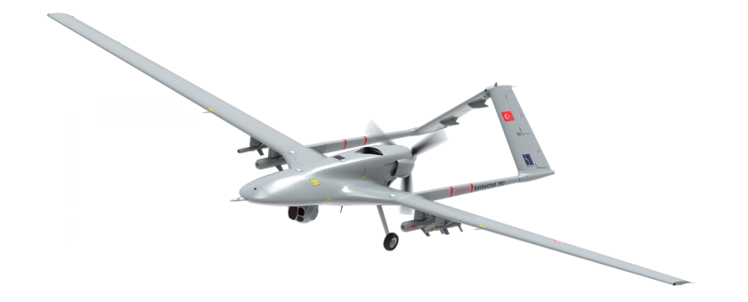
On a defense-related note, apparently the long-running rivalry between Turkey and Greece is, unfortunately, continuing. It seems that Turkey has been repeatedly flying its Baykar-TB2 surveillance drone over Greek islands, perhaps to monitor the movements of Greek warships or island defense installations. And Greece is a little bit more than peeved.
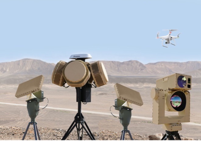
Having established a defense-related relationship with Israel in 2021, Greece has brought Israeli drone defense systems to the Greek islands, installing a “veritable umbrella against enemy unmanned aerial vehicles.” The Israeli system has a number of moving parts: detect and identify; generate related alerts; a directional jamming system that can disable drones in flight (presumably by jamming GPS or the control link); and a laser that can lock onto a small target and, if manually fired, can apparently destroy an intruder drone.
DroneDome elements (Photo: Rafael Advanced Defense Systems)
Because of the directional, narrow beamwidth of the jammer, Rafael claims that the system can be activated within crowded civilian airspace without affecting the navigation of other users. Good news for Greece and their popular, attractive Greek island tourist destinations.
UAV Defense Contractors Struggle — with Each Other
Meanwhile, current economic uncertainty is apparently impacting at least a couple of UAV defense contractors: Boeing/Insitu and Orbital UAV. The two made news when Orbital, as an Australian public company (ASX symbol OEC), had to halt trading. The company was then able to reinstate trading largely because of news of cancellation of a development/production agreement with Insitu.
Apparently, Orbital has previously been delivering two-engine versions to Insitu and was contracted to develop and deliver a third derivative engine. However, Insitu had to scale back Orbital’s work in February, given its sales of the popular ScanEagle and other UAVs may have fallen off in recent months.
Orbital UAV Propulsion System (Photo: Orbital)
This has affected Orbital’s revenue forecast for the year. The company now expects to lose AUD $7 million for the year. It has subsequently prepared a claim under the supply agreement for Insitu’s Termination for Convenience of AUD $1.8 million in costs incurred in the development of the third engine program, which Insitu/Boeing disputes. There will obviously be some wrangling, but hopefully both parties will settle things amicably so as not to damage their ongoing relationship for supply of the existing two engine types.
ScanEagle UAV (Photo: U.S. Navy)
To sum up, for this month we have a trial in the UK which will hopefully lead to significant savings in effort and costs for ongoing power infrastructure inspections, along with some background on UK nuclear waste disposal. Greece is bristling and defending against unwanted Turkish drone overflight using Israeli C-UAS systems. Finally, there’s somewhat negative news for the Orbital UAV engine and Insitu ScanEagle relationship — apparently, not everything in the UAV garden is roses.
Of the 60 exhibitors at the Institute of Navigation’s Joint Navigation Conference (JNC) in San Diego this year, 16 make inertial navigation systems (INS). Many of the other exhibitors integrate INS with GNSS receivers or make simulators to test those integrations. Several exhibitors make a variety of other navigation systems, using active and passive optical sensors, wheel encoders and RF systems that map beacons of opportunity. Only seven manufacturers of GNSS receivers were present.
That’s because the conference — which took place June 6-9 and focused on technical advances in positioning, navigation and timing (PNT) — was hosted by ION’s Military Division for the Departments of Defense (DOD) and Homeland Security. “From an operational perspective,” said the conference program, it focused on “advances in battlefield applications of GPS; critical strengths and weaknesses of field navigation devices; warfighter PNT requirements and solutions; and navigation warfare.” In other words, it was mostly on how to navigate in environments in which the use of GNSS is challenged or denied due to jamming.
The conference program told the story of the GNSS/PNT community’s interests and concerns. Several sessions were on complementary PNT using terrestrial RF signals of opportunity, IMUs, geophysical fields (including gravity and Earth’s magnetic field), celestial objects, ground vision and new commercial sources of space-based PNT, such as satellites in low Earth orbit (LEO).
Other environments in which reliance on GNSS is hard or impossible — such as urban canyons, deep inside buildings, underground and underwater — pose the same navigation challenges to both military and civilian applications. Likewise, jamming is a threat to both. Therefore, several sessions focused on critical infrastructure, demonstrating that the concerns about GNSS vulnerabilities are not just military ones.
Hence the presence among the exhibitors of three manufacturers of atomic clocks, which continue to shrink in size, weight, power and cost (SWaP-C) and are used to assure holdover — that is, the time period required to keep networks synchronized when their primary timing source, usually GNSS, is disrupted or temporarily unavailable. Networks affected include cellphone providers, radio and television broadcasters, financial networks, and the biggest network of all, the Internet.
The JNC “experienced record attendance in both conference participants and exhibitors, hosting more than 1,000 attendees,” Lisa Beaty, ION executive director, told me. She attributed the increase to “the importance of PNT in the nation’s critical infrastructure, current innovation, programmatic funding, and the desire by the DOD community to collaborate and reconvene.” She confidently anticipates additional growth next year.
I am equally confident that much of the cutting-edge technology on display at this conference will find its way into civilian applications in the next few years. Whether in war or in urban canyons, GNSS navigation faces some of the same challenges.
Business Model Enables Mass Adoption of Product with Service
In September 2021, Trimble released its DA2 GNSS receiver with Trimble Catalyst service. I asked Gareth Gibson, the company’s marketing director, Mapping & GIS Solutions, about the product and recent developments in GNSS-enabled mapping.
When I started in this business, more than 20 years ago, we used to divide GNSS receivers into three categories, broadly speaking: consumer grade, resource grade, and survey grade. Are those distinctions still useful?
The survey world and the mapping world have been coming together over the last 20 years or so. Probably Jack Dangermond was one of the first people to publicly acknowledge that. Surveying is an ancient profession whereas mapping and GIS, as an industry, has evolved much more recently. The techniques and the expectations of precision and the complexity of the workflow coming from the survey side has always been somewhat at odds with what the mapping world has been trying to achieve, so the products and the tools of these industries were quite different.
The Trimble DA2 receiver boosts the performance of the Trimble Catalyst GNSS positioning service. (Photo: DroneWorks)
However, there has been a blurring of the lines. Today, the capabilities of mapping-grade GNSS systems are no different from those that can be used in the survey industry as well. Catalyst is an example of that. However, the focus is much more on ensuring that the technology gets out of the way. Let the technology vendor take care of the hard parts, to make it work in the environments where it needs to work, and to make sure it operates with the software that allows the mapping user to focus on the job, with less complexity. We’ve reached that point where it’s difficult to distinguish the capabilities of a survey-grade receiver from those of a mapping-grade receiver. Technically, there’s very little difference.
You can think of Catalyst as renting the performance of the receiver to enable the work to get done. The convergence of technology is enabling the business model transformation, and the business model transformation is aiming to better address the needs of the user. The types of services that these tools enable, the methods with which these tools communicate with homebase and with the vendors—licensing systems, platforms and so forth—have reached a point of enabling delivery of products as a service. That is a good thing because customers are not interested in owning a product as much as they are in getting to the solution that they need.
So, the focus switches from “How do we deliver this product?” to “How do we best deliver this service and the solution?” Catalyst attempts to do that by delivering, in effect, positioning as a service. You are not buying a piece of hardware; you are purchasing the capability to generate and use high accuracy within your workflow to get your job done. That shifts the focus from upfront expense to delivering positioning as an operational cost.
What does the DA2 with Trimble Catalyst service enable that was not previously possible?
It enables the mass deployment of precise GNSS across organizations with tens or hundreds or even thousands of workers. They can now benefit from adding GNSS technology to their work where it was previously prohibitively expensive, too complicated, or simply incompatible with their workflows. Catalyst and the DA2 is enabling that through the business model, which we have employed for the technology, and through the technical capabilities of the platform, which has reached a point of being much easier to be mass adopted across organizations.
The significant change that we’ve made with the DA2 was the addition of support for Apple-based devices. The norm now is to use the phone or the tablet that you have in your pocket, as opposed to purchasing dedicated equipment, especially as it relates to the group of workers we would describe as the location-enabled workforce. These are people typically who are not trained surveyors or GIS professionals but are performing a function with an organization and location-enabled workflows. Software applications are just part of their toolkit for their day-to-day work. It does not make sense to equip these teams with very expensive and complicated equipment, but the functionality that the equipment can provide can unlock some areas of productivity that would have otherwise been inaccessible to them.
What are the remaining technical challenges to mapping for GIS and asset management applications?
The nut that we’ve cracked is enabling precision at almost any practical level, using GNSS, anywhere around the world. We continue to strive towards having access to that level of precision in any environment. There’s a limit to what can be achieved with GNSS alone. So, we start to see more and more the use of combined technologies, different data and sensor fusion. People are leveraging different parts of the technology jigsaw — what is available on their phones, what is available from external sensors, and what they can do with the raw data they are capturing, either directly within a piece of software on their mobile device or somewhere in the cloud, to make better use of the raw information that has been captured.
The second major area is the merging and connecting of workflows, not just the types of data that these organizations are capturing. Organizations are working with field teams, all that data coming together and being able to be used in a toolbox to enable different types of work to get done. In the past, things have been a lot more siloed. Now, technology is enabling us to work together in more clever ways. It is easier to share information.
“The nut we’ve cracked is enabling precision at almost any practical level, using GNSS, anywhere around the world.”
Is accuracy the only difference between surveying and mapping?
For surveyors, the primary deliverable is location. The historical basis of that industry is all about being able to capture and work with information in the most precise way possible. In the mapping world the focus is more on the information that’s being captured about that position, and its precision is just another attribute. That has helped to change our perspective on the relative importance of precision as part of the workflow and has driven us more towards trying to simplify the way that location is captured in a mapping workflow.
Our goal is to capture the most accurate position and to simplify the process for the user. We’ve tried to automate such things as the choice of correction service so that it’s a much more approachable technology and the user can focus on their area of expertise, which is the collection and designation of the mapping attributes.
What are the components of the Trimble Catalyst solution?
There are two elements to Catalyst. One is positioning as a service, enabled through a subscription. The other is the GNSS antenna. The latest generation of that is the DA2. We have made some changes to the DA2 to enable some better functionality and broader applicability. Without a high-quality antenna, there’s only so much that you can do with GNSS. Our focus with DA2 was to make the antenna component of the solution as small and lightweight as possible, but as high performance as possible. We’ve enabled that through a combination of very clever engineering.
The physical structure of the antenna is quite different from that of any other antenna that we build within Trimble. The idea to make it simpler, lighter and lower cost influenced almost every design decision that went into how that antenna is built — from how it fits and mounts with varying carrying solutions to how it is powered. In the first version of Catalyst, we had this notion of running the GNSS receiver as software inside using a computer that was freely accessible and available to every user without needing to burden the antenna itself and create a smart antenna. We said, “Well, if we can deliver GNSS by software, let’s leverage the computing power of the user’s phone or tablet.” So, we took the Catalyst GNSS receiver engine and ran it as an app on a phone.
The Trimble DA2 receiver at work. (Photo: Trimble)
There were some limitations with that approach. We needed to have a fully cabled solution between the antenna and the phone to enable the required bandwidth from the antenna to the software itself, which required a USB connection and put a fairly heavy computational burden on the phone. However, that enabled us to strip out a lot of the excess weight and complexity from the antenna design, which lowered the cost of the antenna. It was a trade-off decision.
With the DA2 we’re acknowledging those changes, plus the limitations that are imposed by wanting to be compatible with the Apple environment of devices. We can still create a very low cost and lightweight computing package to run this same engine in software, but just move that computing resource back into the antenna again. So, it’s still a software defined receiver—effectively a completely different technology from what you would find on a typical hardware receiver.
We have added a wireless radio to allow GNSS positions to be communicated back to your phone or your tablet via Bluetooth. So, DA2 is a lot more versatile because it enables iOS device usage and wireless transfer information from the antenna to the phone or tablet.
Now, how do you make that work as a package to deliver high-precision results? You need access to correction services and a definition of how you want the receiver to behave based on a business model of what consumers are charged. That’s where the subscription component of the Catalyst service comes in. With Catalyst, we want to simplify the way that customers choose what they want and how they get it.
So, rather than purchasing a specific hardware configuration, figuring out what correction services to use, and how to configure them, you simply subscribe to whatever your required performance level is, and Trimble handles the rest. Each subscription is time-based, so it could be annual, monthly, or even hourly. It is a completely managed system that works everywhere in the world.
What are the options for receiving the corrections?
The DA2 supports delivery of corrections over the internet or through the antenna itself — so, in an offline or an online environment. Catalyst uses Trimble’s dedicated correction services, so Trimble VRS Now, which is available in parts of North America and most of Western Europe, as well as Trimble RTX, which is available everywhere in the world and is also delivered by internet or by satellite L band. Globally or regionally available augmentation systems such as EGNOS and WAAS, and those smaller systems for DGPS-type positions, are also used where it’s necessary as a fallback option.
The receiver will choose what correction service it needs to use based on the user’s subscription level and the environment in which the receiver is currently operating. It knows where in the world it is and which license type the user has, so it will try to use the best available source without the user needing to really think about it. The user just specifies to which precision level they want to subscribe — such as one centimeter or 10 centimeters — and the receiver figures out the rest. Catalyst also supports those customers who have their own correction services and want to use it. In most cases, however, that’s not necessary.
Does the current version of Trimble Catalyst differ from the previous version in any other way?
With the latest generation of Catalyst you no longer need a high-end phone to run the service because we have removed the reliance on USB to deliver the data from the antenna to the controlling device. Now, you can effectively do all the computation in the antenna and use Bluetooth for data transfer, which makes it a bit more versatile. Additionally, we have introduced a handle that allows you to use the DA2 in a handheld format that also stores a battery pack.
The biggest leap was certainly the addition of iOS support. After releasing the DA1, we quickly realized that it was not addressing your needs if you were not an Android user it. In North America, more than 70% of business organizations prefer Apple to Android. So, this improvement has more than doubled our addressable customer base. It’s also for those mixed fleet organizations that did not adopt Catalyst because they did not want to have one solution for their Android users and a different one for their iOS users.
What markets and applications are you targeting with it?
We’ve been pleasantly surprised by the response to DA2 and the types of customers that we are seeing. We define our customers in four buckets. One consists of small, independent, non-geospatial businesses, which is a new area for us—the geospatially enabled workforce, people who are using applications that have a location component, who previously would not have been able to justify the purchase of dedicated and expensive equipment. In this bucket I would put landscape gardeners for example, or golf course designers or people who now can create a map much more easily and effectively.
Another consists of consultants and contractors. These are organizations small and large doing geospatial contract work. They are specialists who get sent out into the field to either do mass data collection projects or to consult and provide professional services with a geospatial bent. These are much more traditional customers; they know a little bit more about the technology and what they’re doing. For these customers, Catalyst is a new tool. It enables them to deploy GNSS more broadly across their organizations.
Then there are the sort of organizations and businesses that run their own teams and perhaps have their own GIS department and a field crew dedicated to operating and maintaining the GIS. But they also have the field operations groups, who aren’t geospatially savvy or aren’t geospatial professionals. They’re starting to deploy GNSS across their teams more effectively, as well, because Catalyst is the type of tool that you can keep in the glove box of your car and have available to use at a moment’s notice. So, utilities, municipalities, public works organizations and the like, large federal government agencies in the United States especially.
Finally, the owners of large infrastructure assets, privately owned organizations running ports or oil and gas operations. Again, this is an attractive solution for them. We’re finding that this solution will enable us to address the full range of the market much more effectively.
The May 4-5 meeting of the National Space-Based Positioning, Navigation and Timing Advisory Board focused on its mantra to “protect, toughen and augment” (PTA) GPS. The meeting included three great presentations that bear directly on the A of that mantra.
CAST
The electric grid used to be simpler: regional operators flowed power unidirectionally from stations to customers basing the load on past usage. Now, the grid is becoming a wide-area network — with regional inter-connects, multi-directional flows, and load based on real-time data and predictive analysis, requiring sensors time-synchronized within 1 microsecond from UTC. Yet, this critical infrastructure’s timing applications depend entirely on vulnerable GPS technology.
“If we can provide an authoritative, trusted synchronization source across the interconnected grid, its operators have a much better opportunity to understand the interdependencies and movement of power across their networks,” said Carter Christopher of Oak Ridge National Laboratory. He described the lab’s Center for Alternate Synchronization and Timing (CAST), which provides a redundant and resilient satellite-based service backed up by a network of terrestrial master clocks. CAST is precise, traceable and secure from jamming, spoofing, cyberattacks and physical attacks.
HARS
Attila Komjathy and Larry Romans of NASA’s Jet Propulsion Laboratory (JPL) proposed a GPS high-accuracy and resilience service (HARS) based on global differential GPS (GDGPS). It would provide corrections to GPS orbit and clock errors, and encrypted navigation data bits over the internet. It would match Galileo in accuracy, they said, pointing out that Galileo, QZSS and BeiDou provide high-accuracy services in their broadcast signals. HARS would improve the accuracy of consumer GPS receivers of 3–5 m to 1 m and help ensure that multi-constellation GNSS chips would continue to rely on GPS first.
HARS could be implemented by having commercial providers—such as Apple, Google and cellular carriers—distribute GDGPS corrections generated by JPL and supported by government partners. Private industry, Komjathy and Romans pointed out, provide service for RTK, centimeter and decimeter apps, but only governments (the U.S. Coast Guard’s DGPS service and Galileo’s HAS) provide corrections for about one-meter accuracy. Therefore, HARS would not compete with industry and would create additional opportunities for it to create value-added products.
αPNT
David Castiel and Cyrus Langroudi, of Virtual Geosatellite LLC, proposed αPNT, a virtual geostationary satellite system with elliptical orbits that would provide active PNT in a distributed architecture integrated with a blockchain. The system, they said, would be able to provide very accurate geographical position, precise timing and guidance with a minimum number of satellites on the horizon. It would rely on two-way links between transceivers and satellites to protect against jamming or spoofing.
While GPS’s success makes it a critical and ubiquitous infrastructure, its vulnerabilities require and stimulate exciting new R&D. Stay tuned.
Will GPS modernization and improvements in GPS receivers and antennas reduce or even eliminate the need for correction services for most applications?
Julian Thomas, managing director, Racelogic
“For most applications, I think the answer is yes, the need for correction services will be reduced. When you can get <1m without external corrections, the majority of conventional accuracy requirements are fulfilled. However, increases in accuracy always open up new applications for GPS, so correction services will still be required.” — Julian Thomas
Racelogic
Miguel Amor, chief marketing officer, Hexagon’s Autonomy & Positioning Division
“Correction services will continue to be in demand for those markets and applications requiring precision and accuracy below a few inches, 2-3 sigma confidence levels and high reliability, availability and integrity. While ionospheric errors have been low in the past 15+ years, correction services will also provide ionospheric models beneficial in periods of higher activity. Even as there are improvements in user equipment and signal modernization, the demand for correction services will increase in line with these improvements and new functionalities to enable more markets and applications worldwide.” — Miguel Amor
Hexagon’s Autonomy & Positioning Division