In a slight expansion from our previous monthly UAV newsletter columns, we’re now looking at autonomous systems with a wider outlook, capturing the automated world as it evolves.
The Eve air taxi. (Image: EmbraerX)
News this month covers steps toward air taxi qualification, highly challenging underground UAV and robotic capers, and long-distance watercraft autonomy in Denmark.
EVE gets order boost by Bristow
We’ll soon be seeing them — electric powered manned and unmanned flying taxis buzzing in the city skies above us. Embraer, the Brazilian commuter aircraft manufacturer (you might have taken their EMB-1xx series turboprop aircraft on short hauls between city centers) has apparently progressed its Eve manned/unmanned aircraft development to the stage of a program for qualification/certification being scoped by EmbraerX in Florida and the Bristow Group.
Parent company Embraer established EmbraerX in Melbourne, Florida, as a new-concept UAV developer and manufacturer, launching the Eve urban mobility vehicle as its first product.
Eve subscale demonstrator. (Photo: EmbraerX)
Although we are still only seeing concept-artist renderings of the Eve eVTOL (electric vertical take-off and landing) aircraft, and photographs of a small-scale flying prototype, Embraer has already built an impressive order book. There are reports of more than 500 orders on hand, originally led by Uber and recently joined by the Bristow Group with an order for 100. All orders are likely contingent on aviation agency approval of the aircraft for public transportation.
Based worldwide, Bristow has been around in one form or another since 1955, and currently operates more than 250 helicopters in support of the oil and gas industry, search and rescue (SAR), and various military-related applications, including unmanned aircraft operations with the U.S. Coast Guard. This experience is expected to aid EmbraerX through a joint program to eventually gain an operating certificate for the Eve air taxi.
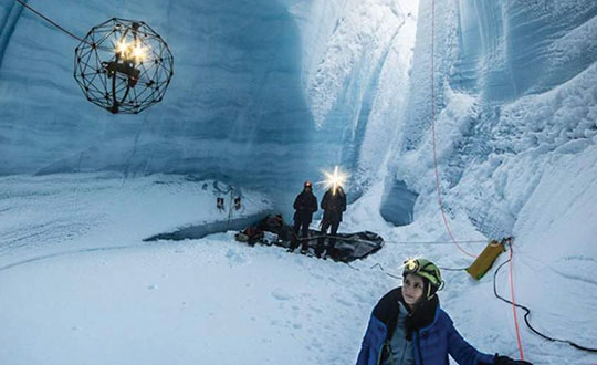
An Elios drone from team CERBERUS roams a moulin in an earlier challenge. (Photo: DARPA)
DARPA’s Subterranean Challenge
The U.S. Army’s Defense Advanced Research Projects Agency (DARPA) has been running a competition since 2018 to find unmanned products and technologies that can find their way around underground environments such as subway systems, sewers, mines and naturally occurring caves and tunnels. The object is to rapidly and remotely map, navigate and search these complex underground locations.
Known as DARPA’s Subterranean Challenge, several groups of competitors were slimmed down to three very capable teams over several months through some initial selection evaluations. Then, on final competition day, teams CSIRO Data61, CERBERUS and MARBLE went at it in an array of challenging environments at the Louisville Mega Cavern — a massive retired limestone mine so large it not only hosts a ropes course and a mountain bike park, but also has tram-guided tours for visitors.
Finalists in the competition had to navigate through elements from previous events, including simulated underground mines, a metropolitan infrastructure, and cave systems. Smoke was even used in places to increase the confusion.
Team CERBERUS — an international consortium that included the University of Nevada Reno (UNR), ETH Zurich, the Norwegian University of Science and Technology (NTNU), the University of California Berkeley, the University of Oxford, Flyability, and the Sierra Nevada Corporation — was ultimately successful.
The ANYmal climbs stairs. (Photo: ANYbotics)
In previous phases of the competition, Flyability used its caged Elios 2 UAV with video and thermal cameras and a high-intensity LED lighting system to create accurate internal maps of underground spaces. However, in the final competition, ANYbotics four-legged ANYmal C autonomous robots were primarily employed — carrying visual and thermal cameras, lidar and a spotlight.
In the final competition, Team CERBERUS managed to locate and identify 23 of 40 hidden “artifacts” in the allocated time and earned the $2 million DARPA first-place prize.
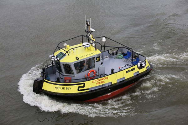
Autonomous Tugboat round Denmark
Sea Machines in Boston has been around since 2015, focusing on automating shipping control and monitoring. It hopes to bring a system to market that will enable an autonomous voyage all the way around Denmark.
With investors who include Toyota Ventures, Huntington Ingalls, Brunswick Corporation, Accomplice and Dolby Fund, the company is not a mega-million venture, but has still successfully engaged the likes of A.P. Moller-Maersk, the U.S. Department of Transportation and the U.S. Navy in autonomous waterborne projects.
The tugboat Nellie Bly on its 1,000 nm circumnavigation of Denmark will use an SM300 autonomous system that uses radar, inertial navigation, a depth transducer, the automatic identification system (AIS) and video cameras for obstacle avoidance. It will provide high-definition remote situation awareness to monitoring controllers in Boston, 3,600 miles away.
Autonomous tugboat Nellie Bly. (Photo: Arie Boer)
Throughout the voyage, the Nellie Bly will have two professional pilots onboard, and will stop at ports along the way to demonstrate the technology. Sea Machines will stream the journey live on a website with updates from the ship, the crew and the command center, enabling real-time and recorded access to “The Machine Odyssey” as the project is now known.
To sum up, lots of autonomous projects are proceeding, with progress toward getting air taxis up and running for business, DARPA sponsoring technology for underground navigating, and mapping and long-distance autonomous navigation around Denmark — lots of diversity and opportunity.
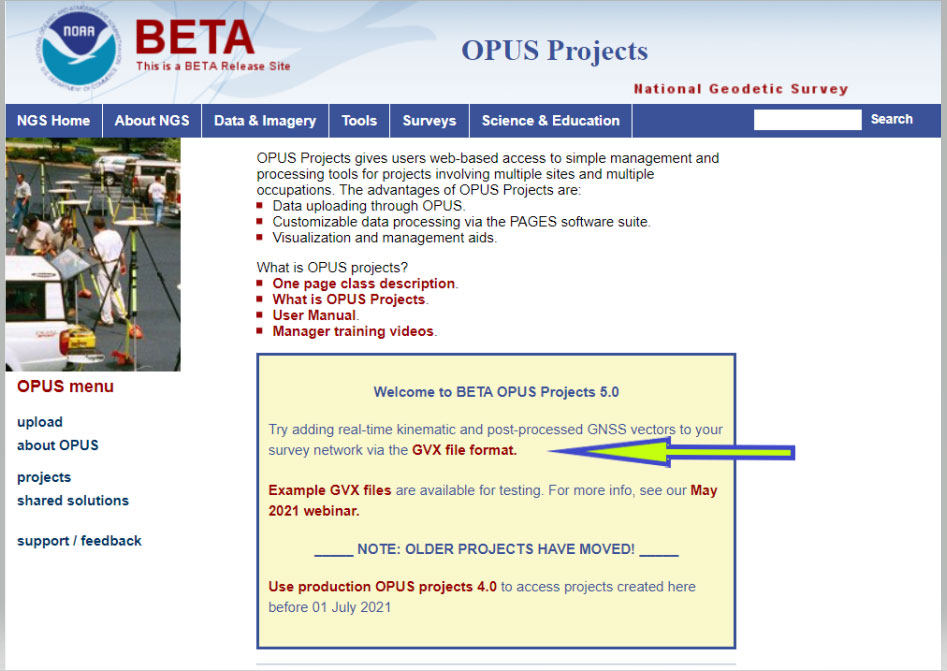
On Sept. 16, the National Geodetic Survey (NGS) released the latest beta version of OPUS, called Beta OPUS Projects 5.0. This version of OPUS now accepts real-time kinematic data and post-processed GNSS vectors from vendor software. See the box titled “Beta OPUS Projects 5.0 Webpage” on the website.
As stated in the announcement, NGS has developed a file format for submitted real-time kinematic (RTK) data and post-processed GNSS vectors from vendor software to NGS. It is denoted as GNSS Vector Exchange Format (GVX). This format enables NGS to incorporate the data into its GNSS processing routines.
This is similar to the original Receiver Independent Exchange Format (RINEX) developed for making post-processing more efficient when combining GNSS data from manufacturers outputting raw GPS data in varying file formats. In my opinion, this is a significant improvement to NGS’s OPUS web utility.
Users can obtain background information about the GVX file format by clicking the link GVX file format. More detailed information about the GVX format can be obtained by clicking on the Documentation link.
Basically, GVX is a standardized format for exchanging GNSS vectors derived from GNSS survey data using any manufacturer hardware and software results (see the box titled “Excerpt from Documentation of GVX”). NGS designed the format so that it included all of the necessary data (including metadata) of a GNSS vector for incorporation into a survey network for performing a least-squares adjustment.
To this end, this document proposes a new standardized file format known as the GNSS Vector Exchange Format (GVX). GVX aims to provide a standard format for exchanging GNSS vectors derived from varying GNSS survey methods and manufacturer hardware. The file format includes all of the necessary data of a GNSS vector for inclusion in a survey network for least squares adjustment, as well as metadata which describes the vector. The format is meant for any type of GNSS vector, whether it was derived in real-time or from baseline post-processing. GVX has been written in extensible markup language (XML). XML was chosen because it was designed to carry and store data in plain text format, it is easy to expand and/or upgrade to new operating systems, and it can be read by both humans and machines.
A sample GVX file can be obtained by clicking on the link titled “Example of GVX file, project day 066, day 052, day 053, day 054.” As NGS states in the documentation, the output can be read both by humans and machines. What’s important is that it can be read by machines so the information can be incorporated into software programs. GNSS vendors have all the information they need to generate the output file to enable users to import the data into OPUS Project 5.0. Users will have to contact their software providers to determine whether their software routines generate the GVX output files.
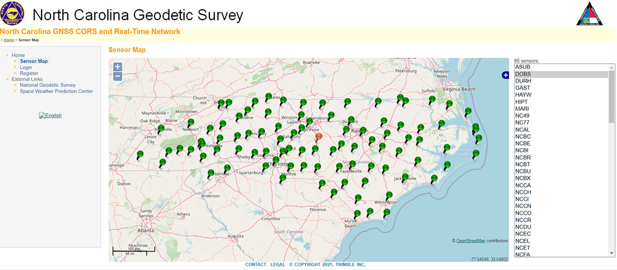
As I previously mentioned, this new option in OPUS Projects 5.0 is a significant improvement because many surveyors use RTK networks to obtain coordinates of marks. It will also facilitate the occupation of benchmarks with GNSS equipment to support the NGS 2022 Transformation tool. North Carolina, my home state, has a real-time network (RTN) that includes 96 GNSS CORS. (See the box titled “NC GNSS CORS and Real-Time Network.”) Currently, the North Carolina GNSS CORS and RTN has 4584 RTN service subscriptions.
I could not find a current list of public RTK networks in the United States, but I did locate a Jan. 7, 2014, GPS World article by Eric Gakstatter that provided a list of public RTK base stations in the country. It’s not up-to-date, but it highlights that, more than seven years ago, more than half of the U.S. states had some kind of public RTK network. I would like to update the table, so I’d appreciate receiving information on the status of any public RTK network. Please feel free to send me an email at [email protected].
California Real Time Network (CRTN) (single baseline). Plate Boundary Observatory. Single baseline.
Colorado
Mesa County (Trimble network) and Plate Boundary Observatory (single baseline).
Florida
Florida Department of Transportation. Leica network.
Idaho
Plate Boundary Observatory (single baseline).
Indiana
Indiana Department of Transportation. Leica network.
Iowa
Iowa Department of Transportation. Leica network.
Kentucky
Kentucky Transportation Cabinet. Trimble network.
Louisiana
Louisiana State University. Trimble network.
Maine
Maine Department of Transportation. Trimble network.
Massachusetts
Massachusetts Department of Transportation. Leica network.
Michigan
Michigan Department of Transportation. Leica network.
Minnesota
Department of Transportation. Trimble network.
Mississippi
University of Southern Mississippi. Trimble network.
Missouri
Missouri Department of Transportation. Trimble network.
Montana
Plate Boundary Observatory (single baseline).
Nevada
Washoe County. Trimble network. Las Vegas Valley Water District. Leica network. Plate Boundary Observatory (single baseline).
New Mexico
Plate Boundary Observatory (single baseline).
New York
New York Department of Transportation. Leica network.
North Carolina
N.C. Department of Environment and Natural Resources. Trimble network. $500 one-time sign-up fee.
Ohio
Ohio Department of Transportation. Trimble network.
Oregon
Oregon Department of Transportation. Leica network. Plate Boundary Observatory (single baseline).
South Carolina
South Carolina Geodetic Survey. Public but charges a usage fee. Trimble network.
Tennessee
Tennessee Department of Transportation. Public but charges a usage fee. Topcon network.
Texas
Texas Department of Transportation. Public but only available to TxDOT employees and TxDOT contractors. Trimble network.
Utah
Utah Automated Geographic Reference Center. Public but charges a usage fee. Trimble network. Plate Boundary Observatory (single baseline).
Vermont
Vermont Geodetic Survey. Trimble network.
Washington
Washington State Reference Network (Seattle Public Utilities). Trimble network. Public but charges a usage fee. Pierce County (Leica Network). Plate Boundary Observatory (single baseline).
West Virginia
West Virginia Department of Transportation. Trimble network.
Wisconsin
Wisconsin Department of Transportation. Trimble network.
Wyoming
Plate Boundary Observatory (single baseline).
Why do I believe that this new option in OPUS Projects 5.0 is so important? Because it facilitates the incorporation of accurate GNSS-derived ellipsoid and orthometric heights into the National Spatial Reference System (NSRS). With the development of improved algorithms, the results of coordinates computed using GNSS CORS/RTNs are more accurate today than ever before. During the last decade, there have been many studies analyzing GNSS data to estimate the accuracy values of coordinates from RTN data.
A study titled “Accuracy of GNSS Observations from Three Real-Time Networks in Maryland, USA” by Daniel Gillins, Jacob Heck, Galen Scott, Kevin Jordan and Ryan Hippenstiel presented at FIG Working Week 2019 in Hanoi, Vietnam, April 22–26, 2019, provided a comparative evaluation on the accuracy of three independent RTNs constructed with differing hardware and software. Their study was based on 486, 5-minute duration GPS + GLONASS network RTK (NRTK) observations. The results indicated that repeat NRTK vectors could be combined to meet 1 cm horizontally and 2 cm vertically (ellipsoid height) accuracies at 95%. confidence. See the box below. It should be noted that the repeat observations should be observed at different times of the day (for instance, separated by > 2–3 hours), as well as, in my opinion, if possible at least more than two different days.
A total of 486, 5-min duration, GPS+GLONASS NRTK observations were collected on nine bench marks distributed over a 4,000 square km area with rovers connected to three different RTNs in Maryland. Each RTN was developed with equipment and software from a different manufacturer, yet all three RTNs performed similarly in terms of accuracy. When differenced with coordinates from a static GNSS survey campaign, the horizontal and vertical RMSE of the NRTK-derived coordinates was 2.3 cm horizontally and 4.5 cm vertically at 95% confidence. Repetitive NRTK vectors on each baseline differed between ± 2.4 cm horizontally and ± 3.4 cm vertically at 95% confidence. As a final accuracy evaluation, hybrid survey networks consisting of repeat NRTK vectors and baseline solutions from post-processing static GPS data collected at RTN base stations and CORSs were adjusted by least squares. Prior to adjustment, the VCV matrices of the vectors were scaled by variance-component estimation. Adjustment of hybrid survey networks with four repeat NRTK vectors per bench mark produced network accuracies at 95% confidence for the adjusted coordinates at all bench marks less than 1 cm horizontally and 2 cm vertically (ellipsoid height).In addition to the benefits of using efficient and accurate NRTK vectors, the hybrid survey network approach makes use of redundant vectors for checking data and avoiding blunders. The approach also provides traceability because the NRTK vectors are tied to an RTN base station which is tied to CORS. Finally, these networks ensure the survey is referenced to the published coordinates of the CORSs which are held as constraints in the adjustment.
Lastly, I would like to remind users that only three months remain until the December 31, 2021, cutoff to submit GPS on Benchmarks data that NGS can guarantee will be analyzed to compute the initial set of 2020.0 Reference Epoch Coordinates (RECs) that will be released with the Modernized NSRS. This initial set of RECs is currently the only set that NGS can guarantee will be used to build the 2022 Transformation Tool. Once the transformation model is finalized, the NAVD 88 – NAPGD 2022 transformation values will be locked in and will not be updated as additional sets of RECs are computed. If you have questions or concerns about this cut-off date, please contact your NGS Regional Geodetic Advisor, or drop NGS a line at [email protected].
Beta OPUS Project 5.0 is a web-based tool that makes it easier to submit data to NGS. I would encourage NSRS users to occupy as many benchmarks with GNSS equipment and submit the data to NGS before the Dec. 31 deadline. Not only will these data help in improving the transformation model, but the marks will be included in the first computation of Reference Epoch Coordinates (RECs). You can obtain information about Reference Epoch Coordinates in NGS’s NOAA Technical Report NOS NGS 67 publication titled “Blueprint for the Modernized NSRS, Part 3: Working in the Modernized NSRS.” A future column will address the different types of coordinates that will be distributed by NGS with the modernized NSRS.
Single-base RTK is an excellent choice for many uses but mixing different baseline lengths can yield inconsistent results
By Gavin Schrock, PLS
Gavin Schrock, PLS
The surveying lead for a construction firm started getting calls from his crews — suddenly they were not checking in to existing control with the accuracy required. This presented a conundrum and an immediate resolution was needed to stay on schedule. What had changed? A nearby permanent base, part of the regional real-time GNSS network (RTN), had suddenly gone dark, and when the crews switched to other bases, they got the inconsistent results. Time to call the RTN. (See a primer on RTN.)
I have been operating a regional cooperative RTN for 19 years, and I get these kinds of support calls regularly, but typically only from users of the single-base mountpoints. Most RTN provide, via NTRIP casters, both network RTK (NRTK) solutions — such as master-auxiliary, VRS and FKP — and single-base solutions for each base. The base they had been using was down while the roof of the city building on which it is mounted was undergoing some maintenance.
The construction firm, halfway through a multi-year transportation project, had used the base when they established project control, and for layout and as-built tasks. Using the base, which was slightly more than 4 km from the site, the crews were used to seeing check-in results of 0.3′ (9 mm) or better (horizontal). When they switched to different bases, 23 km and 25 km distant, the results were now inconsistent, and in many instances, double.
This was an easy fix. We met on site and checked results using the network solution; it closely matched the results they were seeing from the original base. Until the original base was restored, this would meet their needs.
It made a lot of sense to use the nearby base, as setting a temporary project base on the congested and sky-view challenged site was impractical. Furthermore, the baseline length of 4 km yields excellent results. Single-base RTK is a powerful tool, and a default for many construction projects, provided that:
the base has an unobstructed view of the sky
the base is free of nearby multi-path hazards
the base receiver and the antenna are of the same or better quality as the rovers
the base receiver and the antenna support the constellations and the signals desired.
In many ways, it is hard to beat single-base RTK. For instance, if you set up a base right on the site, say less than a kilometer away, this should yield the best results possible for RTK, and can be better than network RTK.
However, there are challenges. Single-base, typically “iono-free” solutions common in today’s rovers, degrades over the baseline length. The rule of thumb for many is that the degradation becomes noticeable when baseline lengths exceed 10 km. It is not uncommon for rovers to fix at much longer baseline lengths; 20 km, 30 km, 50 km or more — but results will likely vary from hour to hour or day to day. Changes in ionospheric and tropospheric conditions can bring inconsistencies, particularly over longer baseline lengths.
Network RTK may not beat single-base over very short baselines, but as it uses 5 to 15 bases (depending on the implementation) it can better model in the varied conditions. It can provide great consistency and repeatability, even if an individual base is unavailable, as was the case for this conduction site. There are strengths and weaknesses for both. NRTK brings consistency over a wide area, you do not have to set up (and guard) your own base, and the geodetic values are solved.
If you can have an on-site base, you can under certain conditions see a gain in results. This is especially important for certain applications, such as machine control and precision agriculture, for which tight year-to-year and row-to-row repeatability is key. However, if you may need to use another base at some point, you may be better off starting with NRTK, if it yields the results you seek.
Gavin Schrock is a practicing surveyor, technology writer, editor of xyHt Magazine and operator of a cooperative GNSS network.
First, there was one. In July 1995, the U.S. Air Force declared the Global Positioning System had met all the requirements for full operational capability (FOC). Soon thereafter, there were two. In December of that same year, Russia’s Globalnaya Navigazionnaya Sputnikovaya Sistema (Global Navigation Satellite System, or GLONASS), also achieved FOC. For a quarter century, that was it.
Then, last year, the number doubled, as both the European Union’s Galileo and China’s BeiDou Navigation Satellite System (BDS, named after the Big Dipper asterism, which is known in Chinese as Beidou) achieved FOC.
The Indian Regional Navigation Satellite System (IRNSS, aka Navigation Indian Constellation, or NavIC, which means “sailor” or “navigator” in Hindi) and Japan’s Quasi-Zenith Satellite System (QZSS, also known as Michibiki) are not global yet, but plan to become so. Currently, NavIC is an autonomous regional satellite navigation system, and NavIC-based trackers are compulsory on commercial vehicles in India. QZSS currently complements GPS to improve coverage in East Asia and Oceania, but Japan plans to have an operational constellation of seven satellites for autonomous capability by 2023. The Korea Positioning System (KPS) plans to join the party by 2035.
Who’s next? Will it be another country or a private company? Given that the state-sponsored systems are free to end users, I don’t see what the business model would be for a private GNSS constellation, unless it were to piggyback on one built mainly for another purpose.
Surveyors who have begun to routinely use three or more constellations are over the moon. One, quoted in this month’s cover story, recalls that “the use of GPS for construction staking was an extremely risky proposition” because its residuals exceeded most construction tolerances. Using multiple GNSS constellations, however, has increased confidence in the accuracy of results to the point that some construction companies are relying on GNSS receivers for staking. Additionally, multi-constellation receivers can now increasingly be used under tree canopies and against structures, whether natural or built.
Whatever their mix of military, political and commercial motivations for building, deploying and operating their own GNSS constellations in addition to the original two, the European Union, China, India, Japan, Korea and whichever entity may follow are greatly improving satellite-based positioning, navigation and timing (PNT) for all users everywhere — by increasing accuracy, shortening the time to first fix, and making GNSS more impervious to jamming and spoofing.
In 1978, the year that the U.S. Department of Defense launched the first NAVSTAR GPS satellite (“NAVSTAR” was later dropped from the system’s name), Neil Young sang “Four Strong Winds” (originally written by Ian Tyson and performed by him with his wife Sylvia as the Canadian folk-duo Ian and Sylvia).
Now, GNSS has “four strong winds,” two lighter ones and several more breezes to follow. As a sailor and a navigator, I welcome them heartily. As this magazine’s editor-in-chief, I don’t mind that, like Jeep, Kleenex, Popsicle and Xerox, GPS probably will stick in popular culture as a generic term for global satellite navigation systems way past its accurate description of what is in the box.
All four current GNSS and two regional systems have been built and are operated by public agencies. Many correction services and complementary PNT services are operated by private companies.
Going forward, what do you expect the division of labor to be between the public and private sectors in building and maintaining PNT capabilities? What should it be?
Ellen Hall
“The space race was championed by governments. Space travel, communications and other technologies were born from government exploration into space. Today we see many private companies engaged in space. Several are intent on supplementing GNSS navigation, and some envision competing. Private companies have a way to go if they plan to compete with systems like GPS, but competition is often at the center of innovation and may benefit everyone.” — Ellen Hall Spirent Federal Systems
Jules McNeff
“GNSS and regional systems are established and sustained to meet the needs of the governments and public agencies that operate them. They cover wide areas and provide services to extremely diverse user communities at levels of performance based on resources that are justified by user requirements and limited by technical affordability. When the global/regional service levels don’t meet the needs of a particular user group or require backup for security, the opportunity is opened for other agencies or private companies to create augmentations and complements to meet the additional needs. The mix is variable and will be determined by the user groups and the market.” — Jules McNeff Overlook Systems Technologies
F. Michael Swiek
“There is really no single ‘correct’ answer or specific division of labor between public- and private-sector entities in GNSS. The situation we see today is the result of decades of constructive and successful ad hoc evolution of roles among and between public- and private-sector entities. Public agencies are better suited to provide foundation technologies and infrastructure due to the large costs and long timelines associated with establishing the constellations and maintaining stable and consistent service. The private sector is better positioned to provide variety and timely flexibility in developing innovative solutions to the broad range of constantly emerging user requirements across all market segments. This unofficial and continually evolving division of labor has worked successfully and continues to adapt to the evolving world of PNT.” —Michael Swiek GPS Alliance
The Ingenuity UAV is still buzzing around on Mars, well past its anticipated evaluation/test lifetime, and is still providing intriguing video and photographic coverage of the surface. Having established that it can fly in the Martian atmosphere and having achieved all its own test objectives, its role is now that of a “pathfinder” — in the truest form of the word — scouting out routes for its big brother Perseverance rover.
The principle objective of the mission remains the search for signs of life, and this is now being performed by the SUV-sized land-bound ground unmanned vehicle (GUV) rover. The project is managed by NASA/Jet Propulsion Laboratory (JPL).
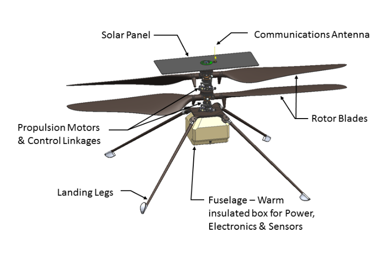
Since our earlier stories covered the phenomenal achievements of the little 2 Kg UAV, it’s reasonable that we provide details of its development and design, largely by JPL and AeroVironment.
Talking with the Ben Pipenberg, the AeroVironment engineering lead for the Ingenuity program, it was clear that the company’s role had been to bring its extensive unmanned experience to the requirements for flight on the red planet. It turns out flying high-altitude pseudo-satellite unmanned aircraft at up to 90,000 feet teaches you a lot about vehicle dynamics in very thin air, and AeroVironment has been doing that for many years. The company developed Ingenuity’s rotor and rotor-drive systems, and the minimal weight structure of the vehicle.
JPL developed the flight-control systems, power system, telecoms and electronics that enabled communications, navigation, guidance, video and control of Ingenuity on Mars.
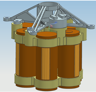
Mars is cold, especially at night, reaching as low as –148 °F. It has few clouds, is a long way from the sun, and has a very thin atmosphere. When JPL decided to use mostly off-the-shelf components, the added task of keeping the electronics warm using minimal power became absolutely essential. Power is provided by a lithium-ion battery pack with its own heaters and temperature control, which is recharged by a small solar photo-electric panel mounted on the top of the vehicle above the rotors.
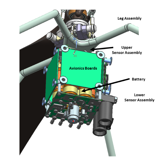
Integrity’s lithium-ion battery, heaters and temperature sensors. (Diagram: Aerovironment)Principle vehicle elements. (Diagram: Aerovironment)
The electronics are carried in the electronics core module (ECM), which is mounted inside the insulated box and mechanically attached to a central, hollow, structural tube, on which the flight motors, rotors and landing legs are all attached. The electronics box has a 3-cm gap between the skin and the ECM, which is filled with inert, insulating carbon dioxide gas — heat retention and power management are the basics for survival on the Mars surface. Keeping the batteries above –15 °C is the design goal for the temperature control system, which also enables the electronics and sensors to survive and operate.
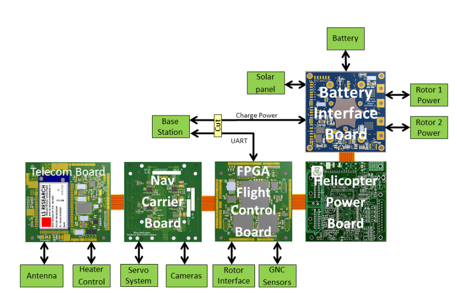
The avionics boards are wrapped around the heated battery-pack with the battery interface board at the bottom, along with the FPGA/flight controller board (FFB), the NAV/servo controller board (NSB), the telecom board (TCB) and the helicopter power board (HPB) mounted vertically. The navigation camera (NC) and the return-to-Earth (RTE) camera are both slung from the front, lower (direction of flight) side of the ECM, peering through a clear window in the insulated box.
The FPGA basically runs the show, managing most tasks, especially two redundant flight controller microprocessors. An additional CPU controls power through several interfaces to the vehicle systems, including the motors driving the rotors. The CPU also runs control software that initiates mode changes based on external commands, and guidance/navigation — using data from the inertial measurement unit (IMU), the nav camera and altimeter — limiting position, velocity and attitude drift. The telecom module manages communications and some power functions, and the power board manages vehicle power.
Off-the-shelf sensors are interfaced to the FPGA and include the nav camera, two dual redundant three-axis micro-electro-mechanical (MEMS) IMUs, an inclinometer for IMU calibration on the surface, and an altimeter. These sensor outputs are used to produce a velocity solution, derived helicopter position and attitude. The nav camera provides images compared frame by frame to stored topography to derive an estimate of vehicle velocity while airborne.
The FPGA is responsible for flight and attitude control, waypoint guidance, maintenance of system time, running a motor-control loop and fault management, as well as providing power management and some thermal control. The FPGA also manages multiple redundant interfaces between the various subsystems, and telemetry communications back to the rover during flight. It also operates the two redundant flight control processors, determining when to switch from one to the other, and provides stored critical data to each processor whenever power is cycled.
As anyone involved in space electronics knows, one of the main design constraints for Integrity was to minimize the effects of single-event upsets (SEUs). SEUs are largely due to cosmic ray effects on electronic components that are not specifically hardened against them. This means most of the electronics used on this particular unmanned vehicle may be susceptible to SEU failures, even though MIL-SPEC, extended-temperature-range components were used wherever possible. Nevertheless, there are dual-redundant IMUs, so one is kept on standby, and the key FPGA is MIL-SPEC, radiation tolerant and has three parallel, duplicated channels. Other components were pre-selected for tolerance to latch-up; a current monitor helps detect such latch-ups with power cycling used to clear these events.
Meanwhile, on Mars Integrity completed its 13th flight on Sept. 4, taking photos toward the southwest of the South Seítah region of Jezero Crater, and flying slower and lower than in previous expeditions. The object was to gather more detail of raised ridges and outcrops from a different angle than the 12th flight — an area in which the science team may have particular interest. It’s possible that the Perseverance rover may soon find itself exploring this area.
Integrity photographs the South Séítah region during its 12th flight. (Photo: NASA/JPL)
As unremarkable as this scene might appear to us laymen, there is a ridgeline in the middle of the above shot where the team may soon decide to send Perseverance to dig, drill and scoop.
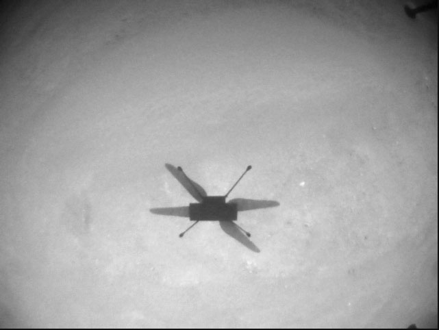
Integrity takes a shadow “selfie” during its13th flight. (Photo: NASA/JPL)
Tony Murfin GNSSAerospace
Acknowledgements
Aerovironment: Ben Pipenberg, the company’s extensive role in the Ingenuity project is summarized in a presentation for the recent AUVSI Xponential convention in Atlanta.
NASA/JPL: Integrity’s development is described in depth in NASA/JLP paper “Mars Helicopter Technology Demonstrator,” which is a principle source of material for this article.
The surveying profession has experienced a plethora of advancing technology over the past two decades and it does not look like there will be a slowdown any time soon. From robotic total stations to laser scanning to the use of multiple GNSS constellations, the profession is constantly adapting these emerging technologies into a useful tool for daily applications. For most practicing surveyors, it is a challenge to keep up with not just the hardware of these advancements, but also with software, which is being developed in parallel. Have you tried to open and draw a simple figure in any of the industry standard CAD programs lately?
The complexity of these programs, while advancing the capability of many technical professions, forces even the casual user to maintain a regular habit of software education and training. While it may seem primitive to say that a practitioner is a “practicing” surveyor, on-the-job training never stops. Just when the profession thinks there are no more significant advancements, something comes out of left field that truly blindsides us. (See the adoption of UAVS by the surveying profession compared to the public sector…) What do I think will be one of the next “big things” to revolutionize surveying? The technology is already here, and we need to seriously get on board with adoption before we miss another opportunity to highlight the expertise of the profession.
VIRTUAL REALITY and AUGMENTED REALITY (VR & AR)
First, we need to know that virtual reality (VR) and augmented reality (AR) are different, even though many people use these terms interchangeably. The differences are as follows:
Virtual Reality (VR)
VR is a virtual world generated by computers and programming.
VR is a closed environment that is fully immersive.
VR requires a device (specialized glasses and/or a headset).
Users in the VR experience are limited by the programming and their computer’s abilities.
The VR experience may be based upon real-world conditions but is a fictional setting.
Users of VR can travel and experience conditions in real and fictitious places.
VR can allow users to have experiences that are not physically possible in the real world.
VR is 75% virtual + 25% real (industry “rule of thumb”)
Augmented Reality (AR)
AR is typically based on actual physical places.
AR is an open environment that is partly immersive.
In AR, the user controls the environment.
AR combines virtual elements and experiences with real world conditions.
Experiences in AR can be accessed by computer, tablet, and smartphones.
AR is useful for product visualization and evaluation.
AR is 75% real + 25% virtual (industry “rule of thumb”)
It is important to know these difference between the two technologies in order to implement the correct one for the task at hand. However, both will play an important in surveying for generations to come.
One of the surveyor’s biggest responsibilities is to complete an accurate site conditions model by topographic methods. Once the topographic survey is completed, site designers will utilize this information to create a unique project that works with the existing site conditions. Advances in CAD software and technology allow engineers and architects to design in 3D and blend the new site with the existing conditions, drainage, and utilities. These designs can be further refined into virtual reality models to give the project’s stakeholders a better indication of what the final product will be when construction is completed.
The key takeaway here is that the surveyor is responsible for delivering the existing conditions model. A model that accurately represents the subject site but in digital form enables the design of the project to be more efficient and realistic to meet the client’s expectation. Surveyers, however, will not use virtual reality as much as augmented reality, for many good reasons.
USES OF AUGMENTED REALITY TECHNOLOGY FOR SURVEYING
AR is still in its infancy. Because surveyors have an interest in the existing and proposed conditions of sites, the use of AR becomes an important tool for the future. Merging proposed information with existing site conditions can become the norm, but like many emerging technologies, the profession will need to learn how to embrace it.
To get a better idea of how the technology works and why surveyors need to consider using it, let us look at an application that showcases AR: Pokémon Go. Yes, the smartphone game app that took the world by storm in 2016 and captivated many “trainers” to search the streets for Ultra Balls and characters. (There are still more than 100 million active players worldwide.) Players of all ages have continued to search for elusive items and characters in a high-tech scavenger hunt that is constantly changing, and all based upon the real world around us. By merging a real-time view with game entities at random geographic locations, players move about our world using one of the best examples of AR.
How does this apply to the surveying profession? Surveyors could utilize AR in everyday tasks but that would require having a fully developed 3D design model that could merge with the existing conditions in their visual device. There are a variety of devices for utilizing AR, including smartphones and tablets. Many of the new data collectors running Windows and Android operating systems can also be used for incorporating AR into the field operation. Here are some examples of AR how can be utilized for surveying tasks:
While construction staking, AR can be used to assist with structure and improvement location. A quick visual check can help confirm staking calculations are consistent with engineering design.
Use AR to visually check installed improvements, including curbs, utility structures, and paving. Any deviation from the proposed design should be quite evident.
When establishing property corners, AR will help the field crew quickly determine whether the calculated location is accessible. This can be used for staking out pre-calculated boundary points and/or proposed lot corners in a new subdivision.
Here are a few ideas as to how surveyors could utilize AR in everyday tasks in the future:
As public utilities are becoming more available within GIS shape files with geographic locations, they could be utilized with AR to help visually establish locations in the field. Mainline utilities and service lines would become easier to physically verify using AR.
Another GIS shapefile entity, the parcel line layer, could be used to help the surveyor understand where the property owner believes the line(s) to be as opposed to the actual monumented location.
All reference monuments and benchmarks established by public agencies using geographic location information could enhance the “treasure hunt” of confirming local datum points.
SURVEYING USING AR TO PROTECT THE PUBLIC
Geospatial information has revolutionized our world, so using AR to help when trouble strikes can potentially be a lifesaver. Recently, an oceanfront condominium in Florida collapsed due to structural failure. While the age of the structure precluded it from having any digital geographic location data, any new similar development could be measured and recorded to assist with future emergency needs. Almost all new development has digital surveying, engineering, and architecture and must use local horizontal and vertical datums. Using the proposed information and verifying with post-construction record drawings, the digital record can be created.
It doesn’t take a design flaw to create a public hazard. For instance, a gas leak could render any building, such as the Florida condo, susceptible to catastrophic damage. By having a digital model of the underground structure, emergency crews could use AR to help locate potential open spaces in the building. As is the case with installing fire suppression systems and emergency exits, the cost to create a digital model of a completed building will be well worth it to save lives.
Underground utility corridors within cities, campuses, or manufacturing facilities could also utilize geospatial locations to establish a digital map for future use with AR. It will take time and significant cost to map existing facilities, yet it should be required for new sites to provide this information for emergencies and for use when designing expansions within the site. Having this utility information to use with AR during the design phase could lead to identifying potential problems before construction starts.
Haiti after an earthquake. (Photo: 1001nights/E+/Getty Images)
Another reason to plan for future safety is how much uncertainty we face in today’s society. At press time, we are coming up on the 20th anniversary of 9/11. We also just watched Haiti suffer another devastating earthquake. The 2021 hurricane season has also been very active, so that danger looms large, too. Disasters happen all the time with little to no warning. Our world is much more advanced than we were at the turn of the century, so we can use these advancements to map our infrastructure. Let us hope we never need to use the digital information for another disaster akin of 9/11. Instead, let us use it to ensure that we can get to someone in a remote spot if necessary.
THE ROAD TO FUTURE MAPPING AND AUTOMATION
As previously discussed, establishing a digital twin of our world could help provide a better map for establishing parcel ownership, reducing construction conflicts, and offering better planning tools for future expansion. Will it be completed within my lifetime? No, and I doubt it will be done within the next couple of generations after me.
We can, however, get a significant start on capturing the necessary information to begin the process of digitization. Technology has exceeded my expectations just within the past decade, so I can only hope that more advancements will help with building this digital beast. More architects and engineers are utilizing BIM (building information modeling) for 3D design and collaboration. Most municipalities and counties have built some form of GIS that uses one of the standard geographic datums. Surveyors have fully embraced GNSS technology so state plane and national geographic coordinate systems have become the norm. In addition, we are seeing a wide number of consultants use autonomous vehicles (aerial, hydro, and terrestrial) with photogrammetry, LiDAR, and SLAM remote sensing. Another bit of good news is that computing power is higher than ever and that storage space is cheap for all this data. We should also include how 5G has expanded our reach and, with cloud storage, we can work from just about anywhere. We can do so much more than most of us ever dreamed of, so we need to leverage that into creating a digital entity that can be helpful.
Photo: RyanJLane/E+/Getty Images
HOW TO IMPLEMENT THE LATEST TECHNOLOGY
Augmented reality is one of many new technologies surveyors need to introduce into their toolbox. Many of you may be asking where to begin; my answer, depending on your age, may offend you.
Hire a Gen Zer. Really.
As a Gen Xer, I have come to realize my limitations on technology and being able to fully implement it. The Z generation, while lacking the experience of us wily old guys, see things much differently. The smartphone/tablet/computer, and even the latest data collectors, are designed with them in mind. They grew up playing computer games based in virtual reality, developed excellent hand-eye coordination, and find efficient ways of getting things done. Our surveying world is almost completely digital (when is the last time a client only wanted paper copies of a plat?), so now is the time to make the leap and ditch the drafting table. We have as much to learn from them as they do from us. Together, we can get the surveying profession ready for the next generations. It has been a great profession for us, so let us hand it off to the Z generation. They will (eventually) be glad we did.
Are ‘”flying cars” unmanned aerial vehicles, manned aircraft, electric aircraft or just regular aircraft? Or perhaps a mix of all of these? Flying cars raise so much interest because of their potential to fulfill the space-age Jetsons promise, with the regular family parking one at their house, then using it to go to work, go grocery shopping and take the kids to school — all the things we do today in cars on roads.
The U.S. Air Force recognized that flying cars could also revolutionize how it operates, and in 2020 started putting effort and cash into promising commercial flying-car ventures. Since then, the Air Force has begun to make progress. Its AFWERX Agility Prime program has helped four companies — Kitty Hawk Aero, Beta Technologies, Joby Aviation and Lift Aircraft — develop prototype commercial flying-cars and expand their capabilities.
The Kitty Hawk Aero Heaviside
Kitty Hawk Aero in Palo Alto, California, has been working on its electric vertical take-off and landing (eVtol) aircraft for several years and claims to have proven its tilting propeller concept through several hundred vertical take-off/landing to horizontal flight transitions.
The aircraft — known as Heaviside — has just been granted airworthiness approval by the Agility Prime program, enabling Kitty Hawk to further participate in specialized trials funded by the Air Force.
Heaviside takes off vertically. (Photo: Kitty Hawk)Heaviside comes in for a landing. (Photo: Kitty Hawk)
The majority of flight testing flown by Heaviside has been remote without on-board crew (one or two pilots). This has enabled Kitty Hawk to expand the flight envelope without risking lives. For instance, you might assume those initial vertical to horizontal transitions could have carried a degree of risk, even though those switches in flight mode are now considered virtually risk free.
Nevertheless, the aircraft is also equipped with an on-board parachute recovery system that has been demonstrated to gently lower the aircraft to the ground in the event of a complete electrical failure. The design has minimized weight, even though the aircraft carries sufficient battery power to provide a range of more than 100 miles. A speed of up to 180 mph has been achieved.
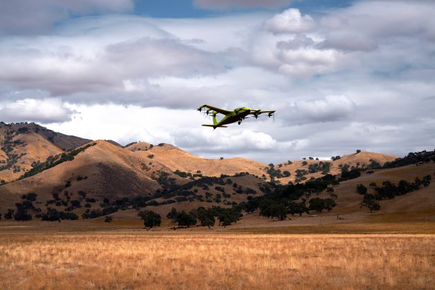
The Beta Technologies Alia
Another AFWERX participant in the Agility Prime project is also well along in its flight test program. Beta Technologies has been flying its Alia prototypes on routes of more than 100 miles and pushing velocities of 150 mph.
Alia eVtol aircraft. (Photo: Brian Jenkins/Beta Technologies)
Alia is large — it’s in the 7,000-pound aircraft category with a 50-foot wingspan. Alia is designed to carry six people over 250-mile routes, with a cargo capacity of 1,500 pounds. It is powered by on-board lithium-ion batteries. The Air Force expressed serious interest in the design and flight-test planning phase before Alia became airborne. The craft has since proven it is capable of safe, reliable flight over routes such as Plattsburg to New York. The Federal Aviation Administration has authorized such flights ahead of time, but Beta also just received additional airworthiness authorization from the Agility Prime office to enable further trials.
The Air Force clearly has great faith in Beta Technologies. The company received an even greater boost to its Beta eVtol program from the commercial sector. BLADE Urban Air Mobility has already ordered 20 of these electric aircraft, and UPS has also ordered 10, with the expectation that their order could grow to up to 150. UPS can clearly see the time and cost advantage of landing aircraft directly at its package-sorting facilities, then loading and vertically launching Alai onto delivery routes, either manned or autonomously as a cargo UAV. United Therapeutics, which is developing artificial organs for human implantation, is another key sponsor, presumably to find the shortest transit time to client hospitals.
Amazon also may become involved following Beta’s recent successful $368 million funding round led by Fidelity and Amazon’s Climate Fund, giving the company stratospheric “unicorn” valuation of more than $1 billion. Maybe there could be Amazon package delivery service in Beta’s future.
The Joby Aviation Craft
Joby Aviation is another earlier participant in the U.S. Air Force’s Agility Prime program and was granted airworthiness authorization in 2020. Joby first flew a subscale prototype in 2015 and a full-size aircraft in 2017, with the objective of proving the viability of a tilt-rotor, four-passenger flying taxi/eVTOL aircraft.
Joby eVTOL in flight in Northern California. (Photo: Joby Aviation)
Joby’s story may be similar to the other companies developing electric flying cars, save that it has been doing this since 2009. Over time, Joby has won significant funding and support from key industry sponsors including Toyota, Uber, Elevate and Agility Prime. A study by Lufthansa in 2021 touted Joby as the leader in the eVtol competition.
The FAA has agreed that Joby can proceed down a certification path applying regular general aviation part 23-64 rules, plus special conditions that include special attention for batteries and fly-by-wire controls. Joby is making good progress toward certification objectives, having already flown more than 1,000 times with different prototypes.
With six tilt-rotors driven by electric motors, Joby’s yet-to-be-named four-passenger aircraft is capable of 200 mph with a +150-mile range, weighs 4,000 pounds and is apparently one of the quietest, measuring only 65 dBA at ~110 yards while hovering. A low noise profile is key to acceptance of these relatively low-altitude flying-cars as they buzz across densely populated areas — and all manufacturers have come up with low-noise-profile designs.
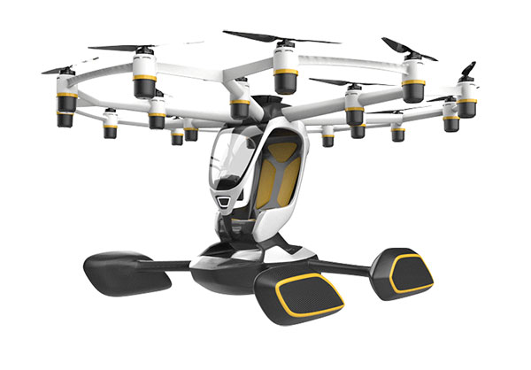
The Lift Aircraft Hexa
Lift Aircraft has taken a different path toward introducing flying-car technology into everyday use by borrowing more closely from existing drone capabilities. The company hopes acceptance will be quicker under its adopted FAA’s Powered Ultralight classification (FAR Part 103), which does not require a pilot’s license to fly.
The Lift approach also intends to take so many precautions and use so much automation that anyone can fly its Hexa. Floats prevent sinking for forced landings on water; triplex flight-computers, GPS and IMUs add to the fail-safe design; and an automatic parachute release in the event of an in-flight incident deploys a “whole-aircraft air bag.” Along with 18 redundant electric-motor-driven propellers (only 12 are needed for a safe landing), these features add up to safety for the uninitiated.
Hexa single-pilot drone-car. (Photo: Lift)
The single joystick control is simple to use and allows the unskilled to fly the drone-car safely. The system comes with extensive monitoring built in, so remote safety operators can intervene in extreme situations. Flight is currently only allowed in geo-referenced airspace defined by Lift. The vehicle has the capability to fly itself out of potentially dangerous situations and avoid mapped obstacle locations. Flight is semi-autonomous and take-off and landings are automated.
Agility Prime joined with Lift in April 2020 to support the company’s safety testing, and in August 2020, funded expansion of the Hexa flight envelope. The Air Force has loaded a Hexa drone-car into a C-130 transport aircraft and flown it to another location to verify transportability for remote deployments. Lift has also won another contract from the Air Force for autonomous cargo retrieval based on a subset of the Hexa design elements.
It is possible that many people will see Hexa in operation during a coming demonstration tour planned for major population centers across America – 15,000 people have apparently already signed up to fly Hexa when the tour gets underway, possibly later this year.
Wrapping It Up
So are these craft flying cars, or drones carrying people? It’s still hard to say definitively, but for sure many experts believe in the forecast of 160,000 flying taxi-cars by 2050, with airport shuttle and air-taxi markets reaching a market value of $500 billion. Certainly the Agility Prime program seems to have got it right and taken the necessary steps to ensure this technology gets out of its emerging, curio stage and out into a world eager to adopt it. If only we could accelerate the extremely lengthy civilian certification phase while still embedding increasing levels of safety. Perhaps the Air Force program can get us there quicker.
How will widespread deployment of 5G most benefit GNSS?
Greg Turetsky
“The connectivity options that widespread 5G offer will accelerate multiple GNSS benefits. The high bandwidth is starting to encourage many into the RTK domain, but I think the bigger opportunity may come from the low power versions that enable IoT applications. The combination of the ubiquity of cellular connectivity with the low power of NB-IoT could truly accelerate the real time asset management sector all the way down to the package/pallet level.” — Greg Turetzky
Allison Brown
“Widespread deployment and adoption of 5G is likely to continue to increase the demand for spectrum as broadband access continues to expand. The recent FCC decision allowing Ligado to operate terrestrial networks in bands near GPS is likely not the last decision that will result from this increasing demand. It is not clear to me that 5G deployment will ‘benefit’ GNSS and chipset vendors may need to prioritize developing products that have improved robustness in the presence of nearby interference.” — Alison Brown
Miguel Amor
“The benefit of 5G will be seen in the long term, when 5G ranging capability is available. Hybrid positioning algorithms using both 5G and GNSS observations will provide significant positioning benefits in challenging urban environments and seamless navigation between indoor and outdoor environments. Applications across markets will see the benefits of hybrid 5G and GNSS navigation, but the real advantage lies in how this hybrid will enable the future of autonomous mobility. We will see both technologies working closer together to deliver a seamless and ubiquitous positioning solution.” — Miguel Amor
Mitch Narins
“Like communications, the ability to precisely and securely position and navigate is an essential part of 21st century life. Together they must support both critical and non-critical operations. This requires finding a common understanding of spectrum needs and how to have the best of both. In the long run, end runs by either side may achieve myopic goals but will damage society. The problem is crying out for an enterprise-level systems engineering leadership that can plot our future spectrum course. Else, the push for spectrum will continue, fueled by ‘entrepreneurial spirit’ and often a lack of understanding of the importance of other spectrum uses.” — Mitch Narins
Additional Loyal Wingman jet-powered drones are being developed. Plus, quadcopters are helping calibrate and maintain aviation ground navigation systems.
I’ve previously discussed the Loyal Wingman project. Companies in the United States and Australia are developing unmanned full-scale jet-powered drones t0 fly alongside frontline fighters, and perhaps take on riskier missions.
The Loyal Wingman drones are powered with artificial intelligence developed for the U.S. Air Force Skyborg program.
Programs in other parts of the world are also developing technology for the same fly-along objectives. The United Kingdom has launched the Lightweight Affordable Novel Combat Aircraft (LANCA) program, and India is working on the Combat Air Teaming System (CATS) Warrior project.
UK LANCA project
The UK usually takes its time progressing with new aviation concepts, but has now awarded a £30 million concept contract to Spirit Aerosystems in Belfast to develop and fly a demonstrator drone by the end of 2023.
Meanwhile, Kratos in the United States and Boeing Australia both have Loyal Wingman UAVs well into flight test programs as part of the Skyborg program. (The first test flight of the Loyal Wingman was successfully completed in February.) Nevertheless, the LANCA schedule should mesh with that of the UK’s next-generation fighter program, known as Tempest, which is just getting started.
Computer rendering of the United Kingdom’s Mosquito drone concept. (Credit: UK Defense Department)
Spirit Belfast is the Irish subsidiary of Spirit AeroSystems (Wichita, Kansas), previously owned by Bombardier (Montreal, Canada) and, before that, Shorts Brothers, Belfast. Spirit was previously involved in manufacturing aerostructures and will apply its unique composite resin transfer-infusion technology to build a high-speed capable, lightweight fuselage for the aircraft.
Spirit has formed Team Mosquito, joining Northrop Grumman UK and Intrepid Minds for flight controls and avionics. An engine supplier and developer has yet to be announced.
CATS Warrior project
On the other side of the world, Indian state-owned Hindustan Aeronautics Limited (HAL) has apparently invested significantly since at least 2019 in a program to develop another Loyal Wingman concept, known as the HAL Combat Teaming System Warrior (HAL CATS Warrior). A mockup of the CATS Warrior was on display at Aero India 2021.
While still in the early phase of development, the program appears to be well into the major undertaking by HAL and its partner Newspace R&D. HAL has been the indigenous aircraft manufacturer for the Indian Air Force since the late 1940s, with facilities in Bangalore and with more than 25,000 employees.
The design goals for the Warrior drone appear to mirror those of the programs in the United States and the United Kingdom — to create an independent, autonomous, unmanned vehicle that can be teamed alongside frontline fighter aircraft as an expendable force multiplier.
Flight inspection drones
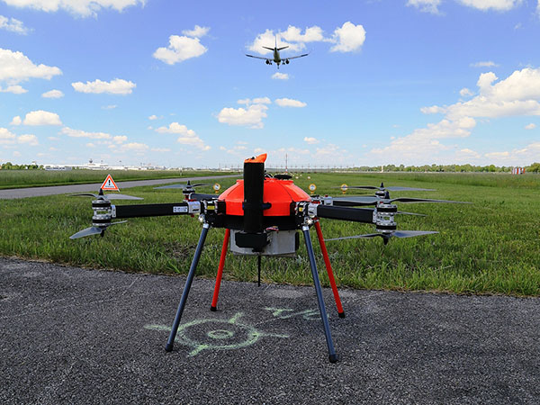
While we’re on the topic of aviation, let’s pull back to more current unmanned applications. News has emerged of a drone being used to inspect a landing-aid system in Russia. Aviation authorities in many countries spend lots of time and money on verifying and calibrating new and existing ground-based landing and navigation aids, to the point of equipping general aviation aircraft with extensive instrumentation and dedicating them to regularly checking key airport and en-route systems.
This is an expensive and lengthy task — all the way from buying, maintaining and operating aircraft to equipping each flying laboratory and maintaining complex onboard equipment, as well as training and employing skilled pilots and equipment operators.
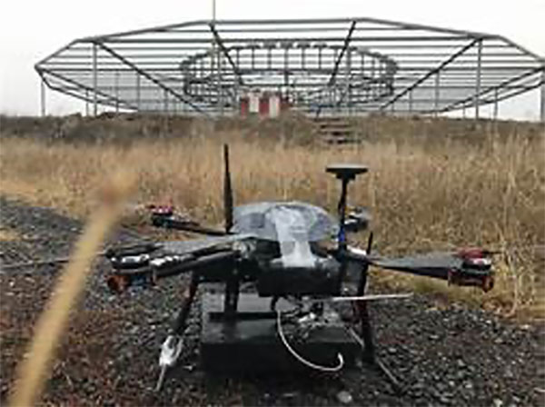
The Cursir nav-aid inspection drone. (Photo: Cursir)
Cursir in Russia has installed a specialized radio receiver on a commercial drone and used it to pre-configure a newly installed instrument landing system (ILS) at the Ulyanovsk-Vostochny airport, where difficult terrain makes the initial set-up of the ILS quite complex.
However, by using this calibration drone, set-up time was significantly reduced and adequate preparations were made for subsequent control flights by a fully equipped flight inspection aircraft. Even though these formal flights were still required, calibration of the ILS was less involved and fewer flights were necessary.
In the future, maintenance checks using only the calibration drone may be possible. Drones have also been in use for complete NAVAID inspection for some time, with companies including Canard in Spain and Colibrex in Germany.
Canard’s drones undertake flight inspection of runway lighting, ILS and other airport NAVAIDS. It uses a database of airports, runways and systems for flight planning, autonomous drone operations and analysis/reporting of collected data. Canard was founded in 2015, and its first flight inspection contract was in 2017 for seven European airports.
The Canard flight inspection drone. (Photo: Canard)
Colibrex built its own COL-X8 NavAidDrone in order to better integrate its in-house flight inspection receivers and antennas. The requirement for flight inspection is to accurately evaluate the signal-in-space being transmitted by the NAVAID, so Colibrex invested heavily in the development of its on-board RF reception and in-house results analysis systems. Early trials were first run in 2012, through many different measurement campaigns around the world; Colibrex has now established an extensive drone flight inspection capability.
The Colibrex NAVAID drone. (Photo: Colibrex)
To sum up, more Loyal Wingman jet-powered drones are in development, and perhaps we now have a little insight into how quadcopters are being used to calibrate and maintain aviation ground navigation systems. These are just a couple more innovative applications for unmanned aircraft.
The U.S. Department of Defense wants help making sense of commercially and publicly available information that could be used to detect GNSS disruptors, especially over large areas.
Obtaining the ability to detect and geolocate GNSS disruptions has been cited as an unmet need in a number of U.S. national policies and plans dealing with positioning, navigation and timing.
The recently posted solicitation calls the project “HARMONIOUS ROOK – Situational Awareness for Intentional Disruption of Global Navigation Satellite System (GNSS) Users.” The solicitation says:
“The Department of Defense (DoD) seeks commercial solutions leveraging machine-driven analytics and datasets derived from publicly/commercially available information (PAI/CAI) to provide a situational awareness capability for intentional global navigation satellite system (GNSS) disruptions. This solicitation is particularly focused on persistent, large-area coverage of falsified GNSS emitters that result in localized spoofing phenomenology.”
Studies and analyses by non-profit organizations and commercial entities have demonstrated the ability of non-governmental organizations to do this kind of work and produce remarkable results. In 2017, our Resilient Navigation and Timing Foundation detected and reported on widespread GPS spoofing in the Black Sea.
This acquisition is being led by the Defense Innovation Unit, or DIU. The unit was specifically created to accelerate the adoption of commercial technology and services by the defense and national security establishments. While letting a traditional DoD contract for a prototype can often take up to 18 months, DIU aims to award contracts within 60 to 90 days of identifying the problem.
To do this, DIU uses the government’s “commercial solutions opening” process, which is designed to be simple and quick.
Companies who provide analytic services and those who have unique data sets are both encouraged to apply. The deadline is August 23.
Dana A. Goward is president of the Resilient Navigation and Timing Foundation
An Interim Armored Vehicle “Stryker” and AH-64 Apache helicopters with Battle Group Poland move to secure an area during a lethality demonstration as part of Saber Strike 18 in June 2018. (Photo: U.S. Army/Spc. Hubert D. Delany III, 22nd Mobile Public Affairs Detachment)
In one of my previous columns, I described the National Geodetic Survey’s (NGS) plans for replacing the North American Vertical Datum of 1988 (NAVD 88) with the North American-Pacific Geopotential Datum of 2022 (NAPGD2022).
As stated in the NOAA Technical Report NOS NGS 64 Blueprint for the Modernized NSRS, Part 2: Geopotential Coordinates and Geopotential Datum, November 2017, recently revised in February 2021, orthometric heights in NAPGD2022 will be defined through ellipsoid heights and GEOID2022. This means NAPGD2022 orthometric heights will primarily be accessed through GNSS technology.
Like NAPGD2022, in the next update of the International Great Lakes Datum, denoted as IGLD (2020), the heights in the Great Lakes Region will be developed from GNSS and a gravity model. Unlike NAPGD2022, where users will be estimating GNSS-derived orthometric heights, IGLD (2020) users will be estimating GNSS-derived dynamic heights using GNSS and a gravity model.
Promote a better understanding of geodesy as a science;
Create a better appreciation of the value of geodetic surveys and thus encourage greater use of such surveys;
Promote geodetic surveys by individuals, government, and private organizations;
Foster the adoption of uniform standards and procedures for completing geodetic surveys;
Promote the processing, publishing, and disseminating of geodetic survey data and information;
Promote programs for testing, calibrating, and evaluating geodetic equipment;
Further the development and implementation of the Global Navigation Satellite System (GNSS) for geodetic, land surveying, and land information system applications;
Inform the membership of new technical developments by meetings of the association and publications in Surveying and Land Information Science (SaLIS);
Promote educational programs in geodesy, geodetic surveying, and related fields;
Cooperate with other similar organizations, both national and international, in support of the science of geodesy;
Encourage the use of geodetic surveys and mathematical coordinate systems in establishing Public Land Survey System (PLSS) corners
As stated above, AAGS cooperates with other similar organizations, both national and international, in support of the science of geodesy. AAGS is a voting member of FIG, which means AAGS has the opportunity to nominate and vote for elected officials, and develop policy that is important to all surveyors and mappers.
The theme of the FIG Working Week 2021 virtual conference was “Smart Surveyors for Land and Water Management: Challenges in a New Reality.” FIG Commission 5 focuses on meeting the highest level of accuracy for positioning and measurement (see box titled FIG Commission 5). Five 90-minute sessions described some of the efforts of FIG Commission 5.
“FIG Commission 5 focuses on meeting the highest level of accuracy for positioning and measurement. It provides the tools, techniques and procedures to educate and train surveying professionals everywhere. Appropriate methodology for data collection and processing are required to be successful in an era of global, integrated geospatial data.”
These sessions raised surveyor awareness of cutting-edge technology, techniques and procedures for using geodetic data and enhanced global cooperation and standardization in conformance with the ideals expressed by the United Nations resolution for a Global Geodetic Reference Frame. There were many good papers on positioning and measurement presented at the virtual meeting. Readers can obtain a list of presentations and papers at this website.
A paper by Jacob Heck, U.S National Geodetic Survey, and Michael Craymer, Canada Geodetic Survey titled “Updating the International Great Lakes Datum: Enabling the Integration of Water and Land Management in the Great Lakes Region” should be of interest to many U.S. and Canadian surveyors. The box below provides a link to the abstract, paper, handouts and video of the presentation.
05.1 – Managing the Land/Water Interface: WGS84 vs. the ITRS
Commission: 4 and 5
Chair: Dr. Mohd Razali Mahmud, FIG Commission 4 Chair, Malaysia
Rapporteur: Dr. Daniel Roman, FIG Commission 5 Chair, United State
Jacob Heck (U.S.) and Michael Craymer (Canada):
Updating the International Great Lakes Datum: Enabling the Integration of Water and Land Management in the Great Lakes Region (11046)
[abstract] [paper] [handouts] [video]
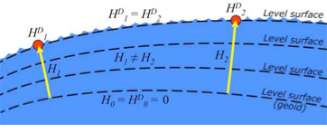
The International Great Lakes Datum uses dynamic heights instead of orthometric heights traditionally used for elevations on land. Figure 4 from Heck and Craymer’s FIG paper, illustrates the difference between orthometric and dynamic heights. See box titled “Figure 4 from FIG Paper by Heck and Craymer.” As described by Heck and Craymer, “The dynamic height represents the difference in potential above the reference surface and is the same at all points on a level surface. Orthometric height represents the actual physical distance above the reference surface which may change due to differences in gravity caused by the convergence of equipotential surfaces toward to the poles. Dynamic heights are therefore required for the proper management of water levels and flows in compliance with international regulations and treaties.”
Figure 4 from FIG paper by Heck and Craymer
Figure 4. Dynamic heights,HD, and orthometric heights, H. (from FIG 2021 paper by Heck and Craymer)
I would like to highlight, as described in the paper and stated in the summary, that access to the future IGLD will be primarily through GNSS techniques.
The International Great Lakes Datum provides a framework for water level management in the world’s foremost resource of surface freshwater. The current datum, IGLD (1985), is being updated and replaced by IGLD (2020). This updated datum will be fundamentally different in terms of definition and access to the datum. The datum will be identical to the new NAPGD2022 North American geopotential datum and will be compatible with the existing CGVD2013 (if not identical as well) at the reference epoch of 2020. IGLD (2020) is expected to be released in 2025 at about the same time as NAPGD2022. Access to both frames will be primarily through GNSS techniques. This will lead to more consistent heights across the entire Great Lakes region. Further information about the IGLD update can be found on the Coordinating Committee website.
This new paradigm is important for anyone who works in the Great Lakes region. Actually, it is important to anyone that surveys in the United States, because this new paradigm will also be used to access the North American-Pacific Geopotential Datum of 2022 (NAPGD2022). Anyone following my columns knows this is the future, and that the National Geodetic Survey (NGS) is leading the way in the United States by modernizing the National Spatial Reference System (NSRS).
Another section that I’d like to highlight is in the box titled “Excerpt from Heck and Craymer Paper on IGLD.”
For IGLD (2020), the geoid height, N, will be provided by GEOID2022 which will be used to define NAPGD2022 and the expected update to CGVD2013. IGLD (2020) dynamic heights will therefore be equivalent to dynamic heights in NAPGD2022 and CGVD2013 at the 2020 reference epoch. For IGLD (2020) heights of water levels, hydraulic correctors may also need to be applied.
An important advancement in the development of the new IGLD and North American datums will be the availability of an accurate crustal velocity model that can propagate ellipsoidal heights between different reference epochs. This will enable heights determined at any epoch to be propagated back to the adopted 2020 reference epoch used for IGLD (2020). This will effectively obviate the need to update the entire IGLD datum for the effects of GIA for a much longer period of time, except for incremental improvements to the velocity model and updates to the reference epoch.
It’s important for users to know that the IGLD (2020) dynamic heights will be equivalent to dynamic heights in NAPGD2022, and an accurate crustal velocity model will be used at any epoch to propagate back to the adopted 2020 reference epoch. The box titled “Determining Heights in IGLD (2020)” is an excerpt from Heck and Craymer’s FIG paper that describes the process that will be implemented for estimating GNSS-derived dynamic heights in the updated IGLD (2020).
In previous realizations of IGLD, spirit leveling was used to determine geopotential numbers which were converted directly to orthometric heights that could then be converted to dynamics heights using equation 4 (𝐻𝐷 =𝐶/𝛾45).
In the geoid-based IGLD (2020), heights will be primarily determined through GNSS techniques which provide a direct measure of ellipsoidal height. Although spirit leveling is more accurate over shorter distances, GNSS methods combined with an accurate geoid model are capable of providing more accurate heights over moderate to longer distances at a small fraction of the cost of leveling.
An orthometric height, H, above the geoid is obtained from a GNSS-derived ellipsoidal height, h, above the reference ellipsoid using the geoid height or undulation, N, of the geoid above the reference ellipsoid. This is represented by the simple equation:
𝐻 = ℎ − 𝑁 (5)
Using equations (2) – (5), the dynamic height can be obtained from the GNSS-derived ellipsoidal height using:
𝐻𝐷 =(𝑔̅ ∗ (ℎ − 𝑁))/𝛾45 (6)
For IGLD (2020), the geoid height, N, will be provided by GEOID2022 which will be used to define NAPGD2022 and the expected update to CGVD2013. IGLD (2020) dynamic heights will therefore be equivalent to dynamic heights in NAPGD2022 and CGVD2013 at the 2020 reference epoch. For IGLD (2020) heights of water levels, hydraulic correctors may also need to be applied.
An important advancement in the development of the new IGLD and North American datums will be the availability of an accurate crustal velocity model that can propagate ellipsoidal heights between different reference epochs. This will enable heights determined at any epoch to be propagated back to the adopted 2020 reference epoch used for IGLD (2020). This will effectively obviate the need to update the entire IGLD datum for the effects of GIA for a much longer period of time, except for incremental improvements to the velocity model and updates to the reference epoch.
As stated by Heck and Craymer, hydraulic correctors may also need to be applied to meet IGLD (2020) International policies, procedures and regulations. Information on IGLD (1985) hydraulic correctors can be found on NGS Geodetic Tool Kit Page.
Another paper presented at FIG Working Week that would be of interest to surveyors is a paper on establishing a geoid-based vertical datum given by Dan Roman, Chief Geodesist at NGS (see the box below). Again, the abstract, paper, handouts and video can be downloaded from the link.
05.1 – Managing the Land/Water Interface: WGS84 vs. the ITRS
Commission: 4 and 5
Chair: Dr. Mohd Razali Mahmud, FIG Commission 4 Chair, Malaysia
Rapporteur: Dr. Daniel Roman, FIG Commission 5 Chair, United State
Roman Daniel (USA): Determining an Optimal Geoid-Based Vertical Datum (10876)
[abstract] [paper] [handouts] [video]
Roman discusses the concept of establishing an International Height Reference System (IHRS) so all countries could provide physical heights across their boundaries and over the oceans (see the boxes titled “Excerpt from FIG Paper by Dan Roman” and “Summary from FIG Paper by Dan Roman “). I’ve highlighted several sections that are important to establishing a IHRS.
The IHRS is relatively recent compared to the ITRS. Ihde et al. (2017) discussed plans for unification of heights globally, which were updated more recently in Sanchez et al (2021). Just as ITRF realizations are made within the ITRS, there will be IHRF realizations made within the IHRS. The key concept here is that positions will first be realized in the ITRS and then expressed in the IHRS. This means that GNSS-accessed geodetic coordinates will determine your position in a realization of the ITRF. Using those ITRF coordinates, geopotential values will be determined from an equivalent IHRF model based above a datum of W0 = 62,636,853.4 m2 s-2. This effectively gives your position in the Earth’s gravity field, which is a physical height. In adopting such a model then, all countries might provide consistent physical heights across their national boundaries and over the oceans.
There is a great deal of activity in modernizing how geospatial data are collected, processed and maintained globally. International agreements are in place to have everyone adopt the Global Geodetic Reference Frame to facilitate geospatial data transfer. The approach will be to realize coordinates in the International Terrestrial Reference Frame and then obtain physical heights from the International Height Reference Frame. Countries may adopt any realization of the ITRF but are restricted to a single geopotential value in the IHRF – W0 = 62,636,853.4 m2 /s2. If comparisons to local tide gauges demonstrate this is not optimum for national definitions of a vertical datum, then an alternate geopotential datum can be determined based on an approach that requires supplemental information.
GNSS-observations on multiple tide gauges will establish local Mean Sea Level and any variations due to Topography of the Sea Surface. A model of the TSS would be required to remove TSS effects at tide gauges to determine the geodetic coordinates of MSL. Use of a geopotential model enhanced by locally obtained gravity data would yield the geopotential number(s) at tide gauge(s). Assuming multiple tide gauges, then an average or some statistical analysis might be made to determine the optimal geopotential value to select as a geoid.
NGS’s new modernized NSRS will be compatible with the concept of an International Height Reference Frame. As stated in Roman’s paper, a recent article by Laura Sanchez, et.al, describes a strategy for the realization of the IHRS (see box below.)
Authors: Laura Sánchez, Jonas Ågren, Jianliang Huang, Yan Ming Wang, Jaakko Mäkinen, Roland Pail, Riccardo Barzaghi, Georgios S. Vergos, Kevin Ahlgren and Qing Liu1
Abstract
In 2015, the International Association of Geodesy defined the International Height Reference System (IHRS) as the conventional gravity field-related global height system. The IHRS is a geopotential reference system co-rotating with the Earth.
Coordinates of points or objects close to or on the Earth’s surface are given by geopotential numbers C(P) referring to an equipotential surface defined by the conventional value W0 = 62,636,853.4 m2 s−2, and geocentric Cartesian coordinates X referring to the International Terrestrial Reference System (ITRS). Current efforts concentrate on an accurate, consistent, and well-defined realisation of the IHRS to provide an international standard for the precise determination of physical coordinates worldwide. Accordingly, this study focuses on the strategy for the realisation of the IHRS; i.e. the establishment of the International Height Reference Frame (IHRF). Four main aspects are considered: (1) methods for the determination of IHRF physical coordinates; (2) standards and conventions needed to ensure consistency between the definition and the realization of the reference system; (3) criteria for the IHRF reference network design and station selection; and (4) operational infrastructure to guarantee a reliable and long-term sustainability of the IHRF. A highlight of this work is the evaluation of different approaches for the determination and accuracy assessment of IHRF coordinates based on the existing resources, namely (1) global gravity models of high resolution, (2) precise regional gravity field modelling, and (3) vertical datum unification of the local height systems into the IHRF. After a detailed discussion of the advantages, current limitations, and possibilities of improvement in the coordinate determination using these options, we define a strategy for the establishment of the IHRF including data requirements, a set of minimum standards/conventions for the determination of potential coordinates, a first IHRF reference network configuration, and a proposal to create a component.
I have highlighted several statements in the box titled “FIG Working Group 5.3.” This working group is focused on issues associated with implementing vertical control based on an International Height Reference Frame (IHRF). NGS is working with these groups to ensure that the United States height system will be compatible with the rest of the world.
I encourage everyone to visit the FIG website and explore the papers given during 2021 FIG Working Week. Here is a list of the FIG Commissions. For more information can be obtained on each commission by clicking on the Commission’s title.
Before the American Congress on Surveying and Mapping (ACSM) disbanded, the four-member organization collaborated to convene annual surveying and mapping conferences in the United States. Topics similar to those presented at FIG Working Week were presented at these conferences. I became a member of ACSM in 1972 and learned a lot from attending and participating in these conferences.
Since these ACSM conferences are no longer being held, I encourage users of geospatial data and GNSS technology to participate in professional societies such as AAGS to enhance their understanding and knowledge of new technical developments in the field of geospatial positioning and measurement. As the current president of AAGS, I am biased, but a benefit of AAGS membership is access to the Surveying and Land Information Science (SaLIS)journal that publishes new technological developments related to geodesy, surveying, and mapping.