Category: Opinions

  • NGS releases annual experimental geoid models and gravity interpolation tools

    NGS releases annual experimental geoid models and gravity interpolation tools

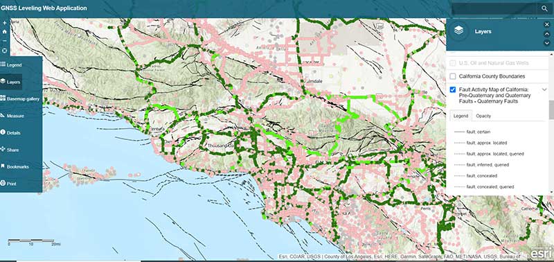
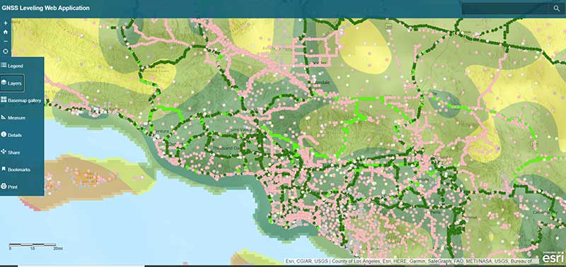
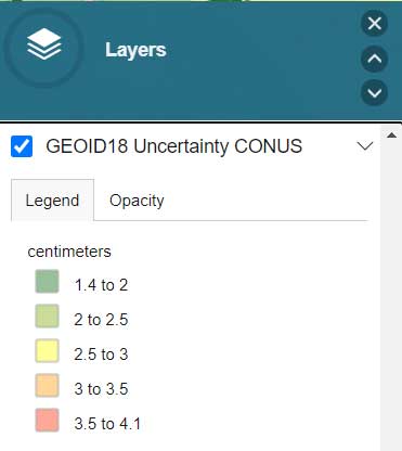
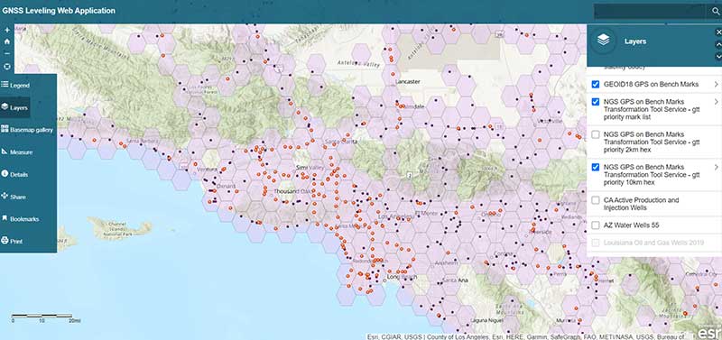
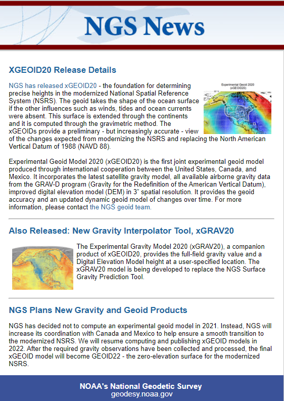
    My last column highlighted an ArcGIS web application that incorporates various datasets and data layers to assist surveyors planning vertical control surveys. On Jan, 29, the National Geodetic Survey (NGS) released the latest experimental geoid model, xGeoid20, and a new gravity interpolation tool (see box below, “NGS Releases Annual e& Gravity Interpolation Tools”).

    This newsletter will highlight some attributes of these two new products. First, why am I writing about another experimental geoid model. I discussed xGeoid18 in my December 2018 column and xGeoid16 in my June 2017 column. What’s important here is that this will be the last experimental geoid model until 2022, and the dynamic geoid model has also been updated this year in the form of xDGEOID20.

    xDGEOID20 is produced by NGS within the Geoid Monitoring Sƒervice (GeMS) and is part of the new NAPGD2022. Therefore, users only have a few more years to understand the differences between the hybrid geoid model that is being used today to estimate GNSS-derived orthometric heights and the gravimetric geoid model which will be used to estimate North American-Pacific Geopotential Datum of 2022 (NAPGD2022) GNSS-derived orthometric heights.

    NGS also announced a new gravity tool, denoted as “The Experimental Gravity Model 2020 (xGRAV20).” xGRAV20 is designed to provide a full-field gravity value and a digital elevation model height at a-specified location. The xGRAV20 model will be important to users that are computing leveling-derived orthometric heights consistent with NAPGD2022.

    It is important to note that the xGEOIDs provide a preliminary but increasingly-accurate view of the changes expected from the upcoming NAPGD2022. Also, the xGEOID20 geoid model is the first combination of the geoid models computed by scientists at NGS and Canadian Geodetic Survey (CGS). One unique element to xGEOID20 is that the differences between the A and the B model are due to the contribution of the GRAV-D airborne gravity and differences in methodology.

    The National Geodetic Survey (NGS) has published annual experimental geoid (xGEOID) models since 2014. Each of these experimental geoids demonstrate the improvements provided by the addition of airborne gravity data (GRAV-D data) and by the refinement of geoid computation methods.

    NGS Releases Annual Experimental Geoid Models & Gravity Interpolation Tools. (Image: NGS)
    NGS Releases Annual Experimental Geoid Models & Gravity Interpolation Tools. (Image: NGS)

    First, users can access the xGeoid20 model here. See the box titled Experimental Geoid Models 2020 (xGEOID20).

    Experimental Geoid Models 2020 (xGEOID20). (Image: NGS)
    Experimental Geoid Models 2020 (xGEOID20). (Image: NGS)

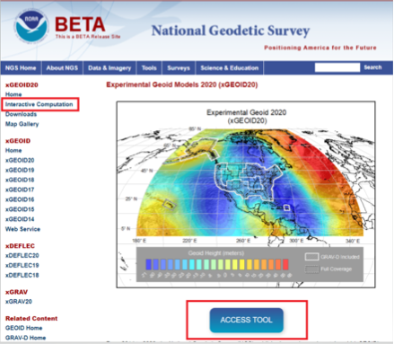
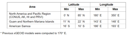
    As the image above indicates, the xGEOID20 is available over a very large area. The box below lists the latitude and longitude boundaries of the areas where xGeoid20 is available.

    Areas Where xGeoid20 Model Is Available. (Image: NGS)
    Areas Where xGeoid20 Model Is Available. (Image: NGS)

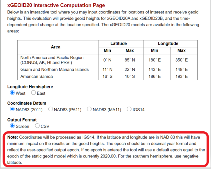
    To use the xGeoid20 Interactive Computation Page, the user can click on the “ACCESS TOOL” button below the map or the Interactive Computation button on the left side of the webpage (see the image above, “Experimental Geoid Models 2020 (xGEOID20)”). I’d like to highlight a statement that NGS added as a note on the computation page:

    1. Coordinates will be processed as IGS14.
    2. The epoch should be in decimal year format and reflect the user-specified output epoch. If no epoch is entered, the tool will use a default epoch equal to the epoch of the static geoid model, which is currently 2020.00.

    The user needs to know that the epoch is used to compute the xDGEOID20 value. I will demonstrate how this works later in this column.

    xGEOID20 Interactive Computation Page. (Image: NGS)
    xGEOID20 Interactive Computation Page. (Image: NGS)

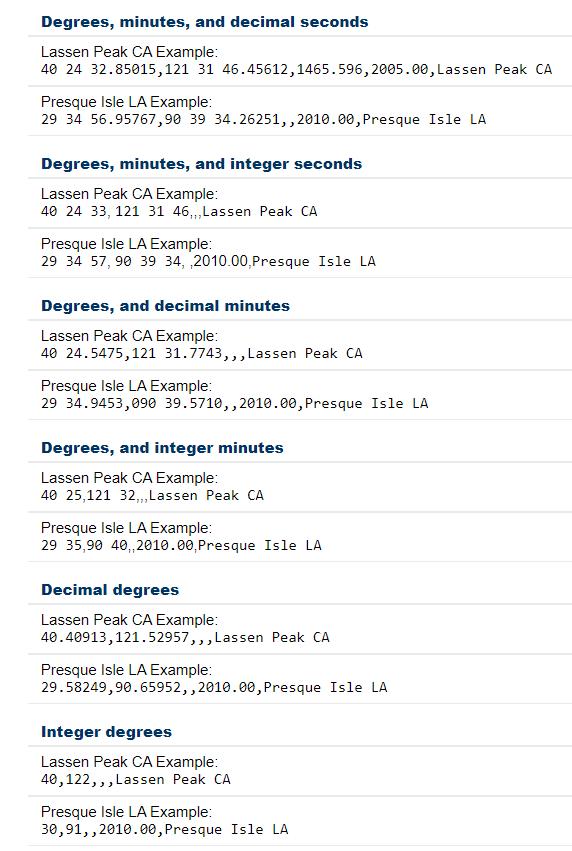
    As in past xGeoid interactive computations web applications, the user can submit data in various formats. The box titled “Input Formats Permitted for xGeoid20 Webtool” provides a list of the permitted formats. It should be noted that inputting an ellipsoidal height, epoch and name are optional. However, the default epoch is 2020.00, so if you want a different epoch, you need to enter the date. Also. the program will only compute an orthometric height if the user provides an ellipsoidal height.

    Input Formats Permitted for xGeoid20 Webtool. (Image: NGS)
    Input Formats Permitted for xGeoid20 Webtool. (Image: NGS)

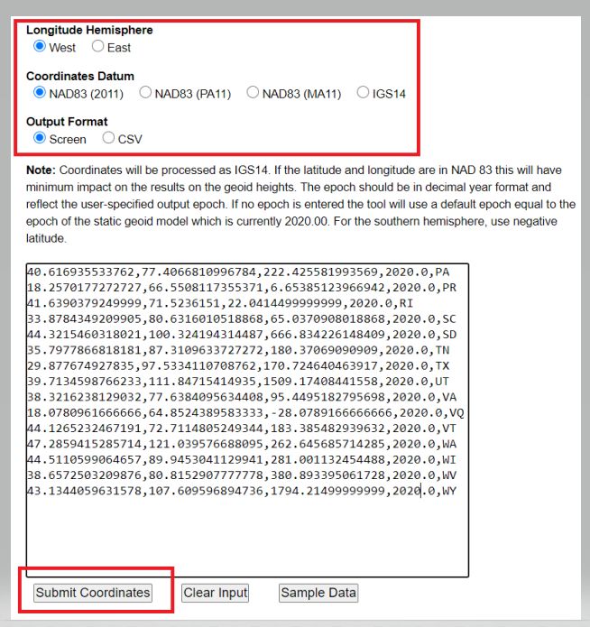
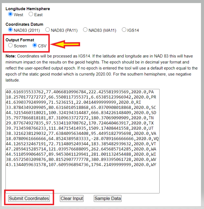
    Users have the option of getting the output from the xGeoid20 tool on their computer screen or in the CSV format. The box below is an example of inputting data using the screen option. Once you enter your data, the user clicks on the submit button.

    Example of Input Format for Screen Option. (Image: NGS)
    Example of Input Format for Screen Option. (Image: NGS)

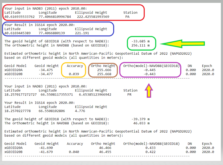
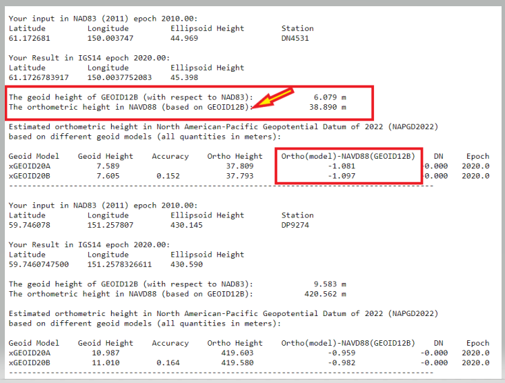
    The next image shows an example of the output using the screen option. I have highlighted a few numbers that I’d like to address.

    • Your input in NAD83 (2011) epoch 2010.00 (red). I entered my coordinates as NAD 83 (2011), and it assumed that these coordinates are epoch 2010.0.
    • Your Result in IGS14 epoch 2020.00 (blue). The routine provides your output coordinates in IGS14, epoch 2020.00. This is the epoch of the static geoid model.
    • The geoid height of GEOID18 (with respect to NAD83) and the orthometric height in NAVD88 (based on GEOID18) (green). This NAVD 88 value is for comparison purposes only. It is using GEOID18 and provides an estimate of the differences between the future NAPGD2022 and the current NAVD 88. The orthometric height is computed using the following formula: NAD 83 (2011) ellipsoid height (epoch 2010.0} minus GEOID18.
    • Ortho Height (brown). This is the estimation of the orthometric height using the following formula: IGS14 ellipsoid height (epoch 2020.0} minus xGEOID20A (or B).
    • Ortho(model)-NAVD88(GEOID18) (purple). These differences are the estimates of the differences between the future NAPGD2022 and the current NAVD 88. It provides the differences for both the xGeoid20A and xGeoid20B model. I look at the B model because it used the GRAV-D data in the development of the model.
    • Accuracy (yellow). This is the estimated 95% confidence interval for geoid height.

    Example of Output Format from Screen Option

    xGEOID20 Interactive Computation Output

    Note: The GRS80 ellipsoid is used for both NAD83 and IGS14.

    N: The geoid height at epoch t0 = 2020.0, which is geocentric and relative to the GRS80 reference ellipsoid.

    Accuracy: Estimated 95% confidence interval for geoid height.

    DN: The time-dependent geoid change computed between user inputted epoch (t) and t0. To obtain the dynamic geoid height at user inputted epoch (t), add N + DN.
    Either Model A or Model B N values may be used for this depending on user preference.

    Example of Output Format from Screen Option. (Image: NGS)
    Example of Output Format from Screen Option. (Image: NGS)

    The box below shows an example of inputting data using the CSV option.

    Example of Output Format from CSV Option

    Note: The GRS80 ellipsoid is used for both NAD83 and IGS14.

    N: the geoid height at epoch t0 = 2020.0, which is geocentric and relative to the GRS80 reference ellipsoid.

    Accuracy: Estimated 95% confidence interval for geoid height.

    DN: the time-dependent geoid change computed between user inputted epoch (t) and t0. To obtain the dynamic geoid height at user inputted epoch (t), add N + DN. Either Model A or Model B N values may be used for this depending on user preference.

    Cnt,Station,NAD83_Lat,NAD83_Lon,NAD83_Eht,Input_Epoch,
    IGS14_Lat,IGS14_Lon,IGS14_Eht,Output_Epoch,GEOID18_
    Ht,Oht_NAVD88,xGEOID20A_Ht,xGEOID20B_Ht,xGEOID20A_Accuracy,
    Oht_xGEOID20B,Oht_NAVD88,Oht_Diff(xGEOID20A-NAVD88),Oht_Diff(xGEOID20B-NAVD88),DN,Epoch

    0,PA,40.616935533762,77.4066810996784,222.425581993569,
    2010.00,40.6169445389,77.4066880139,221.191,2020.00,
    -33.685,256.111,-34.475,-34.477,0.039,255.666,255.668,
    -0.445,-0.443,0.000,2020.0001,PR,18.2570177272727,66.5508117355371,
    6.65385123966942,2010.00,18.2570227778,66.5508102806,
    4.776,2020.00,-39.379,46.033,-41.690,-41.679,0.040,46.466,46.455,
    0.433,0.422,0.000,2020.000

    Example of Input Format for CSV Option. (Image: NGS)
    Example of Input Format for CSV Option. (Image: NGS)

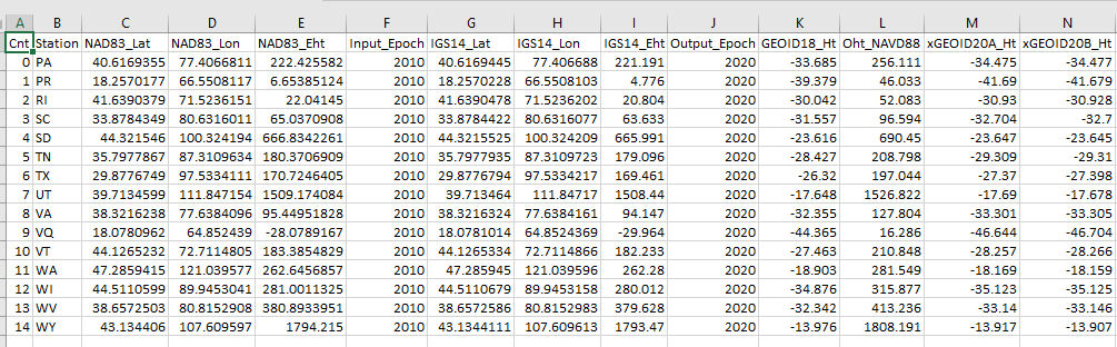
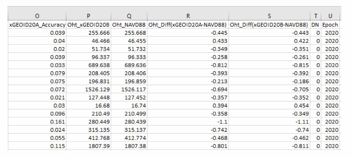
    The printed output from the CSV option looks very confusing, but it can be imported into an excel spreadsheet. The headings and values are all separated by a comma so everything falls into the appropriate columns after importing the data (see image below.)

    Example of CSV Output Format Imported into Excel. (Screenshot: David Zilkosky)
    Example of CSV Output Format Imported into Excel. (Screenshot: David Zilkoski)
    Example of CSV Output Format Imported into Excel. (Screenshot: David Zilkoski)
    Example of CSV Output Format Imported into Excel. (Screenshot: David Zilkoski)

    I stated in the xGeoid20 write up that the dynamic geoid model has also been updated this year in the form of xDGEOID20. This model is produced by NGS within the Geoid Monitoring Service (GeMS) and is part of the new NAPGD2022. For a thorough discussion on GeMS and the time-dependent geoid, view the webinar from NGS’ presentation library. See the box titled “GeMS Webinar by Kevin Ahlgren.”

    GeMS Webinar by Kevin Ahlgren (available at https://www.ngs.noaa.gov/web/science_edu/presentations_library/). (Screenshot: David Zilkoski)
    GeMS Webinar by Kevin Ahlgren (available at ngs.noaa.gov/web/science_edu/presentations_library). (Screenshot: David Zilkoski)

    Also, one of my previous columns described NGS’ GeMS program. The images titled “Examples of the Time-Dependent Geoid Change in Alaska EPOCH 2020.0” and “Examples of the Time-Dependent Geoid Change in Alaska EPOCH 2025.0” show the change in geoid value from Epoch 2020 to Epoch 2025 for two stations in Alaska.

    Examples of the Time-Dependent Geoid Change in Alaska EPOCH 2020.0. (Image: NGS)
    Examples of the Time-Dependent Geoid Change in Alaska EPOCH 2020.0. (Image: NGS)
    Examples of the Time-Dependent Geoid Change in Alaska, EPOCH 2025.0. (Image: NGS)
    Examples of the Time-Dependent Geoid Change in Alaska, EPOCH 2025.0. (Image: NGS)

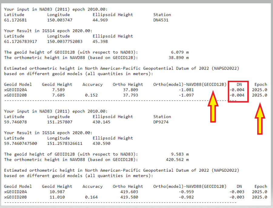
    First, looking at the box titled “Examples of the Time-Dependent Geoid Change in Alaska EPOCH 2020.0,” the change between NAPGD2022 and NAVD 88 is approximately 1 meter. Users should note that the GEOID12B is used to establish the NAVD 88 height. Alaska was not included in GEOID18. Comparing the two Alaska labeled boxes, the xDGEOID2022 change between 2020.0 and 2025.0 is –4 mm. I will address this topic in more detail in future newsletters.

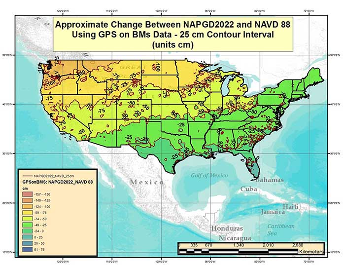
    As stated by NGS news announcement, “The xGEOID models provide a preliminary but increasingly-accurate view of the changes expected from the upcoming North American-Pacific Geopotential Datum of 2022 (NAPGD2022).” NGS has produced many figures that describe the bias and trend between the future NADGP2022 and NAVD 88. In my June 2017 column I provided a plot that depicted the difference between NAPGD2022 and NAVD 88 based on the GPS on Bench Mark dataset. See the image below.

    Figure from June 2017 Survey Scene column. (Image: NGS)
    Figure from June 2017 Survey Scene column. Approximate Change Between NAPGD2022 and NAVD 88 Using GPS on BMs Data (units = cm). (Image: NGS)

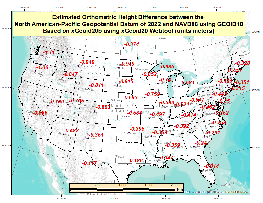
    These figures provide a broad picture of the change but to better understand the changes across the Nation, I used the GPS on Bench Mark dataset, that was involved in the creation of Geoid18 model, to compute an average latitude, longitude, and ellipsoid height for every State. Obviously, this is a fictitious mark but it provides an idea of the average change based on marks that have both a GNSS-derived ellipsoid and a leveling-derived orthometric height. The plot titled “Difference Between the Future NAPGD2022 and NAVD 88” depicts the average difference for each state based on the GPS on Bench Mark data file. These differences were generated using the xGeoid20B values from the output of the xGeoid20 website.

    Difference Between the Future NAPGD2022 and NAVD 88. (Image: NGS)
    Difference Between the Future NAPGD2022 and NAVD 88. (Image: NGS)

    I would encourage everyone to select a couple of marks and compute the differences to understand the change in their particular region. I was the NAVD 88 Project Manager and I informed users of the potential changes between the NGVD 29 and NAVD 88 for about a decade, and I still had surveyors tell me that they didn’t know it was coming. Please take a few minutes to read NGS’ write up on xGEOID20, estimate the differences in your area of interest, and spread the word to your colleagues, friends, and clients.

    The last item that I’d like to highlight is that NGS has released a beta version of a surface gravity model consistent with xGEOID20. See the box titled “Experimental Surface Gravity Model 2020 (xGRAV20).” Users can access the beta webtool here.

    Experimental Surface Gravity Model 2020 (xGRAV20). (Image: NGS)
    Experimental Surface Gravity Model 2020 (xGRAV20). (Image: NGS)

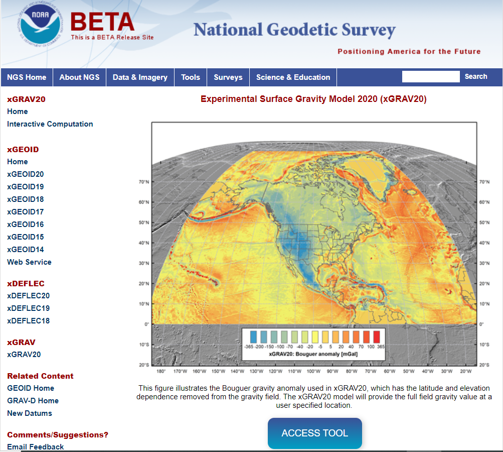
    The access and input to the tool is similar to the xGEOID20 web tool. Saying that, I’d like highlight a few items:

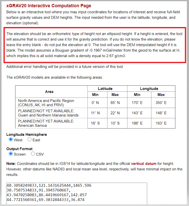
    • The input height should be an orthometric type of height not an ellipsoid height.
    • If a height is entered, the tool will assume that is correct and use it for the gravity prediction.
    • If you do not know the elevation, leave the entry blank. The tool will use the DEM interpolated height if it is blank.
    xGRAV20 Interactive Computation Page. (Image: NGS)
    xGRAV20 Interactive Computation Page. (Image: NGS)

    The box below provides the output using the tools sample data.

    Output from Screen Output Format from xGRAV20 Tool. (Image: NGS)
    Output from Screen Output Format from xGRAV20 Tool. (Image: NGS)

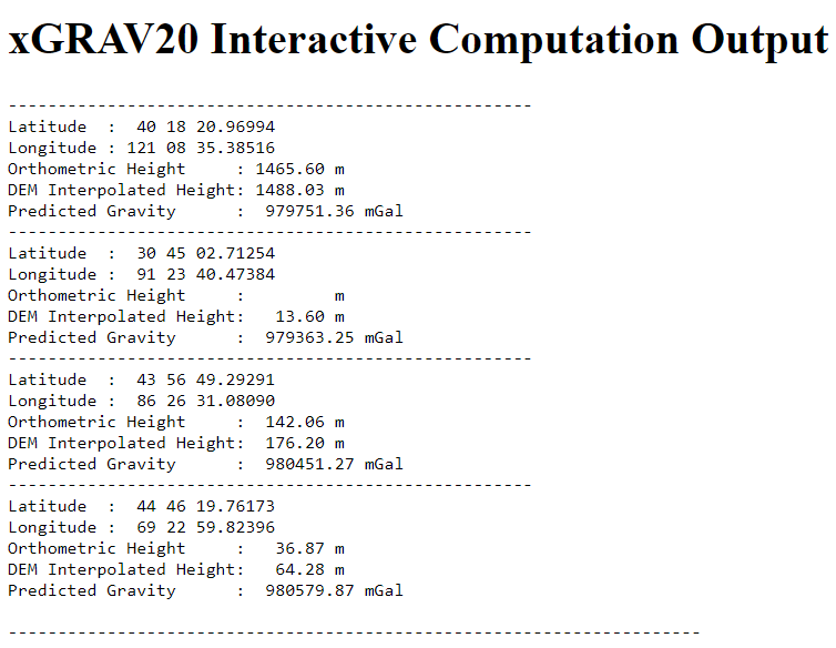
    This gravity tool will be important when users want to incorporate leveling-derived orthometric heights into NAPGD2022. We will address this tool in more detail in future newsletters. I want to emphasis that these two web tools are beta sites. As a beta site, users should verify all information from the site. I encourage everyone to access the tool and check out a few of their favorite marks, and then send an email to NGS informing them of what you like, what you would like to change, and what you would like to see added to the tool.

    NGS is releasing this tool as a beta product to get feedback from users. They are interested in your feedback concerning its function and usability as well as how users would like to interact with NGS web tools in the future. Email NGS at [email protected].

    In conclusion, I want to leave you with a thought about change. When I give presentations and seminars, I usually include a slide that probably expresses the thoughts of many individuals.

    My brother once told me:

    “If you geodesists did it correctly the first time you wouldn’t have to keep performing adjustments and changing the values. Just do it right the first time.”

    He’s a doctor and said he must do it right the first time.

    My response to my brother and to everyone else is the following:

    If you want to improve you have to be willing to change, and if you want to continue to meet future positioning requirements you need to continually change.

    Winston Churchill said it better “To improve is to change; to be perfect is to change often.”

  • Brad Parkinson offers 5 ways to protect, improve PNT

    Brad Parkinson offers 5 ways to protect, improve PNT

    What should the new administration’s priorities be to make PNT more resilient?

    We asked Brad Parkinson, the “Father of GPS” and a GPS World Editorial Advisory Board member, what the new U.S. administration’s priorities should be to make positioning, navigation and timing (PNT) more resilient. For more answers from board members, see below.

    Brad Parkinson
    Brad Parkinson

    Protect the Spectrum. Reverse FCC authorization for relatively high-powered Ligado transmitters that have been proven to degrade GPS and other GNSS operation for thousands of PNT users. All U.S. government departments and major user groups affected have pleaded with the FCC to reverse this terrible decision. There is little benefit from it to the American public.

    Protect the rapidly evaporating and self-proclaimed Gold Standard of GPS. The GPS satellite designs are showing their age. They need to go to multiple launch (three at a time) and revert to simpler designs without the spot-beams and other weighty add-ons that greatly increase complexity and cost. The Chinese have added to BeiDou (a) inter-satellite precision ranging and wide-band communications, (b) geosynchronous satellites, probably with good spot-beam acquisition aids, and (c) a WAAS-like correction directly on the satellites, which may have accuracies down to real-time kinematic (RTK, perhaps a few centimeters). Also, they claim their basic accuracies to be better than GPS (it might be true!) — I think they already have operational retro-reflectors.

    Allow and encourage export of the basic and quickest fix to jamming and spoofing for high-value PNT users. More than 40 years ago, we demonstrated, in hardware, a high anti-jamming receiver that could fly directly over a 10 kW GPS jammer and not be affected. We know that high-gain, digital beam-steering antennas will create close to immunity, but our manufacturers will not move this way because we cannot sell or use them on the international market.  These devices, combined with inexpensive inertial components and the newer signals, would make PNT virtually immune to current threats of interference — both jamming and spoofing.

    Move the military focus from alternative PNT techniques to seriously upgrading their receivers and useful signals. No current or reasonably anticipated alternative can provide the accuracy (3D), availability or integrity of GPS. The new M-code and L1C signals have been in the queue for about 20 years. (Loran for ground operations probably is very vulnerable to direct attack in a fluid battlefield operation. Loran’s main value is to distribute time and for maritime users.) In those 20 years, we now have cellphone chips costing less than $5 that can listen to about 200 ranging signals and process RTK, as well as use all the corrections available (WAAS, EGNOS, etc.). Such capability cannot be found in military receivers. The Defense Department must improve its acquisition strategy in terms of both speed and competition, and ncorporate existing civil capability into military user equipment.

    Take government actions to rapidly identify, shut down, and prosecute GPS jammers. Some believe this problem is much larger than recognized already. All cellphones should be required to report extraordinary spectrum noise levels or apparent attempts at spoofing. This should be fed to a dynamic national database, perhaps maintained by the Coast Guard. GPS users should have an automated way to find out whether there are substantial threats in their operating area.


    Brad Parkinson is the Edward Wells Professor, Emeritus, Aeronautics and Astronautics (recalled) and co-director of the Stanford Center for Position, Navigation and Time at Stanford University.


    Editorial Advisory Board PNT Q&A

    Here are additional responses to the question from more GPS World Editorial Advisory Board members.

    John Fischer
    John Fischer

    “We hope the new administration continues on the path established with the Executive Order last year for resilient PNT, supporting progress made by DHS and NIST in establishing resilient and cybersecure frameworks. It will be important for them to maintain an open market concept toward future innovative solutions and not mandate a particular PNT approach. Awareness of the criticality for trusted PNT in our mobile connected society is established and we must not lose this.”
    John Fischer
    Orolia


    Jules McNeff
    Jules McNeff

    “Resilient PNT should be a national security priority. Its continuity is vital to both military and economic/social activities of all kinds. Its qualities of spatial awareness and synchronization enable the efficient functioning of the most sophisticated modern technologies in the physical and cyber worlds while also simply getting people and things from point A to point B on schedule. In that context, the elements which comprise resilient PNT should be protected from natural or hostile disruption.”
    Jules McNeff
    Overlook Systems Technologies


    Greg Turetzky
    Greg Turetzky

    “Truly resilient PNT requires combining multiple positioning technologies to maximize resiliency. However, the government’s influence in many of the augmentation technologies (sensors, vision, etc.) is limited. What the administration can do is make GPS itself more resilient by speeding up the launch and acquisition schedule of GPS Block III. The new signals, particularly at L5, are invaluable for improved resiliency to jamming and spoofing as well as providing a significant improvement in accuracy.”
    Greg Turetzky
    Consultant

  • Editorial Advisory Board PNT Q&A: PPP versus RTK

    Editorial Advisory Board PNT Q&A: PPP versus RTK

    Every month, we ask members of our Editorial Advisory Board to weigh in on a topic. For the January 2021 issue, we asked,

    Will precise point positioning (PPP) replace real-time kinematic (RTK)? If so, for which applications and when?

    Headshot: Miguel Amor
    Miguel Amor

    “Recently, Hexagon’s Autonomy & Positioning division demonstrated RTK levels of performance — globally —through PPP technology; we call it RTK From the Sky (see page 29). I believe that PPP adoption rates will grow significantly in the coming years and eventually replace RTK — especially in areas that are not well served by RTK networks or similar services. Adoption rates will depend on which applications can field GNSS receivers capable of the signals and constellations to perform like RTK.”

    Miguel Amor
    Hexagon’s Autonomy & Positioning division


    Headshot: Alison Brown
    Alison Brown

    “For many applications, the improved accuracy provided by PPP (10 cm) is sufficient and RTK solutions are not needed. However, the typical convergence time of PPP is between 20 and 40 minutes, depending on the number of satellites available, satellite geometry, the quality of the correction products, the receiver’s multipath environment, and atmospheric conditions. This slow convergence compared to RTK solutions will limit application for many real-time applications such as mobile solutions.”

    Alison Brown
    NAVSYS Corporation


    Jean-Marie Sleewaegen
    Jean-Marie Sleewaegen

    “PPP-RTK combines near-RTK accuracy and quick initialization times with the broadcast nature of PPP, over internet or L-band. PPP-RTK can be seamlessly integrated into GNSS receivers, bringing convenient sub-decimeter accuracy to applications where configuring RTK is not practical or where there is no internet connection. PPP-RTK is likely to be adopted by emerging mass-market applications such as UAVs, while RTK will probably remain prevalent in applications where it is already well established, such as precision agriculture.”

    Jean-Marie Sleewaegen
    Septentrio


    Photo:
    Bernard Gruber

    “I do not believe that PPP will replace RTK technology solutions anytime soon. Satellite-based GNSS correction services with an emphasis on global provide worldwide access, but achieving the required accuracy, due to convergence, can be slow. Today, myriad users and emerging customers may utilize corrections augmented with RTK transmitter/base stations that hybrid solutions can provide, thus solving both the age-old navigation issue of obscuration and near real-time positioning simultaneously.”

    Bernard Gruber
    Northrop Grumman

  • Use of autonomous vehicles in mining and farming touted at CES 2021

    Use of autonomous vehicles in mining and farming touted at CES 2021

    After years of testing and hype, not a lot of companies can say there are real applications for autonomous technology. However, at this year’s virtual CES 2021 trade show, both Caterpillar and John Deere, two companies known for their tractors and heavy equipment, showcased autonomous machines that are being used worldwide in farming and mining projects.

    Photo: Caterpillar
    Photo: Caterpillar

    Deerfield, Ill.-based Caterpillar, a first-time exhibitor at CES this year, said it has been involved in autonomy and use of GPS for more than two decades. “We were an early adopter of GPS when there were few satellites in the sky,” said Denise Johnson, company group president, resource industries. “We have 350 autonomous trucks operating 24-7 on three continents.”

    The company’s autonomous vehicles, in addition to other technology, are being used around the clock in the Kearl Oil Sands project in Alberta, Canada.

    “We are using autonomy primarily in mining operations in harsh environments. These [vehicles] are operating 24-7, with no loss time incidents,” said Bill Dears, Caterpillar worldwide sales and marketing manager. “We also track people underground with cameras and radar.”

    In addition to production enhancement, safety is a factor in mining operations because of operator fatigue — something that is precluded by autonomous mining equipment, Dears said.

    Agriculture uses variety of sensors, including GNSS

    To Moline, Ill.-based John Deere, exhibiting at the trade show for the third time, agriculture is a high-tech industry that uses GPS, self-driving tractors, artificial intelligence and a multitude of sensors. The company rolled out its first self-driving tractors nearly 20 years ago, said Jahmy Hindman, John Deere CTO.

    Photo: John Deere
    Photo: John Deere

    The company won the CES Innovation Award for one of its tractor and combine product lines. “Both our planter and tractor have GPS and antennas to know where to drive and where exactly fertilizer [is to be placed],” Hindman said. “These tractors are self-propelled, with accuracy augmented with [real-time kinematic] sub-inch accuracy for the planters in a field.”

    Among other requirements, Hindman said that tractors have to drive in a straight line, plant the required amount seeds and position them at the right depth. “When a tractor drives in a very straight line, the burden is off of the farmer. The yields increase—this is the way we see the progression of automation,” he said. “We are excited about 5G and its lower latency and high bandwidth. It opens up a lot of opportunity.”

    Organizers roll out Indy Autonomous Challenge race car

    At the virtual CES, representatives from the Indy Autonomous Challenge unveiled the Dallara IL-15 race car that will be used in a head-to-head race around the famous Indianapolis Motor Speedway on Oct. 23.

    The Indy Autonomous Challenge, organized by Energy Systems Network and Indianapolis Motor Speedway, pits 500 university students, developing autonomous vehicle technology, against each other for a $1.5 million prize.

    Logo: Indy Autonomous Challenge
    Logo: Indy Autonomous Challenge

    Organizers say the speeds are estimated to be as much as 200 mph around the 2.5-mile track, for 20 laps, which enables researchers to evaluate how autonomous vehicle technology works in extreme conditions. They say that the goal of the race is to advance the implementation of autonomous vehicles and advanced driver-assistance systems (ADAS), much like the 2005 Defense Advanced Research Projects Agency (DARPA) Grand Challenge.

    The race track has been the scene of much innovation throughout the years, said Doug Boles, Indianapolis Motor Speedway president. “Firestone tests tire technology there and that data transfers to our cars. One of the first conversations we had with Roger Penske [after Penske Entertainment bought the speedway] was about the autonomous challenge,” he said.

    IAC sponsors include ADLINK, Ansys, Aptiv, AutonomouStuff, Bridgestone, CU-ICAR, Dallara, Indiana Economic Development Corp., Microsoft, New Eagle, PWR, RTI, Schaeffler and Valvoline.

    Mobileye plans to test autonomous fleets in four cities

    Intel subsidiary Mobileye plans to launch autonomous vehicle fleet testing in Detroit, Paris, Shanghai and Toyko. The announcement, made at CES by CEO Amnon Shashua, said that the company also plans to test in New York City, pending regulatory approval.

    The company also plans to use in-house-built lidar sensors, while continuing to champion its camera-based testing. “We are using crowd-sourced data through the Cloud to build high-definition maps at scale,” Shashua said. “Thousands of product vehicles are sending us data.”

    Shashua addressed a moderator’s question that cameras alone cannot be the technology of choice for autonomous vehicles. “The camera first is crucial from a technology and business point of view. We have to find out what is acceptable failure for Level 4 autonomy. Camera-only is ideal, but pushing the envelope for driver-assistance systems,” he said. “Consumer AV will take place in the 2025 timeframe. [Eventually], we can build lidar and radar to the same performance levels as camera systems. Lidar and radar can be added later for redundancy, but only for Level 4.”

    Shashua said getting to Level 4 could take a decade, but that would be unsustainable unless there are government-funded projects to keep companies afloat. “By 2025, a subsystem will be good enough for consumers. Regulation is critical and sometimes it’s difficult to leap to a consumer level,” he said.

    Not everyone believes what Mobileye is testing constitutes “driverless” status. To Alain Kornhauser Princeton University professor and transportation program director, who was head of the university’s team during the 2005 DARPA Challenge, not many companies are capable of full driverless capability.

    “Unfortunately, I still see all of this as simply ‘eye candy’ to sell something that actually has no intention of delivering what it is implying. I still claim that the business case is zero, doesn’t exist, for personally-owned autonomous vehicles,” Kornhauser said in his Smart Driving Cars weekly newsletter. “Mobileye is nowhere close to being able to operate safely on most roads, let alone all roads. Thus, the consumer market has zero opportunity to scale.”

    Kornhauser said that driverless testing is being conducted only in one place, Phoenix, by Waymo. “Neither Tesla nor Mobileye are driverless anywhere. They both require on-board human driver supervision,” he said. “That’s why they are only self-driving [tests].”

    In other CES news:

    • GM CEO Mary Barra unveiled a single-seat electric vertical takeoff and landing (eVTOL) concept aircraft. The aircraft will be developed for future use as an air taxi. Barra briefly mentioned that the company’s Super Cruise self-driving technology will be integrated into 22 car models in a few years. The company also rolled out an electric vehicle for deliveries that can travel 250 miles on a charge and a motorized pallet for deliveries that can be tracked.
    • Photo: Mercedes-Benz
      Photo: Mercedes-Benz
    • The Mercedes-Benz’ MBUX Hyperscreen, rolled out at CES, evaluates map data, surroundings and provides information about landmarks along a route, said Sajjad Khan, company CTO and member of the board of management. The new map feature, called Mercedes Travel Knowledge, allows a passenger or driver to ask a question as they drive by a landmark (“hey, Mercedes, what can you tell me about this building?”). The MBUX Hyperscreen is available in the new S-Class cars.
    • HERE Technologies introduced a mapping-as-a-service platform at CES. The platform is targeted to businesses wanting to create custom map datasets for advanced analytics and services, the company said. Some use cases include industrial yard mapping, leveraging probe data from private vehicle fleets in order to create or update a map.• A virtual CES is hard to get used to. After more than 20 years of covering the massive trade show in person, covering press conferences and conducting interviews online was sometimes a challenge. Sometimes the press conferences did not have question-and-answer sessions, or canned answers given to executives by public relations people. This doesn’t happen much during an in-person interview. In addition, trying to chat with “booth” personnel online was cumbersome and often those requests for information were ignored.
  • First Fix: New year, new opportunities for GNSS industry

    First Fix: New year, new opportunities for GNSS industry

    Headshot: J. David Grossman
    J. David Grossman

    By J. David Grossman
    Executive Director
    GPS Innovation Alliance

    As we embark on a new year, 2021 ushers in a new administration and the start of the 117th Congress. With these changes comes a litany of opportunities, as well as challenges, for the nearly four-decade-old GPS industry.

    Next month, the GPS Innovation Alliance (GPSIA) will mark its eighth anniversary as the voice of the GPS industry, educating policymakers and regulators about the GPS success story of innovation, economic growth and job creation. It is a uniquely American story made possible because of bipartisan support for protecting the spectrum used by GPS and maintaining funding to enable the modernization of the GPS constellation, ground control and military ground user equipment.

    Congressional Support. This commitment was evident in the last Congress through broad support from both parties for two Congressional resolutions, H.Res.219 and S.Res.216, that affirmed the importance of continuous availability, accuracy, efficiency, robustness, reliability and resiliency of the GPS constellation.

    Innovation and modernization of the GPS constellation are well underway. Last year, under the emerging leadership of the U.S. Space Force, two new Lockheed Martin-built GPS III satellites were launched into space. This new generation of GPS satellites offers three times greater accuracy, up to eight times improved anti-jamming capability for military users, and the addition of the L1C signal to enable interoperability with other navigation systems, such as Europe’s Galileo.

    GPS modernization also has led to the introduction of M-code, an advanced, new signal designed to improve anti-jamming and anti-spoofing, as well as to increase secure access to military GPS signals for U.S. and allied armed forces. In GPS-denied environments, M-code reduces the jamming radius, giving military planners and targeteers options to minimize or avoid collateral strike damage.

    With at least two additional GPS III satellites set to launch this year and a new ground control segment known as the Next Generation Operational Control System (OCX), the continued success of the GPS program remains bright.

    Ligado Still Looms

    As GPSIA continues to urge Congress to allocate the funding needed to support the modernization of GPS, we also are fighting to ensure uninterrupted operation of the estimated 900 million GPS devices in the United States ranging from precision agriculture to consumer gadgets.

    Last year, we were deeply disappointed by the Federal Communications Commission’s (FCC) decision approving the applications of Ligado Networks, despite the well-documented objections of the expert agencies charged with preserving the integrity of GPS, specifically, on the critical issue of what constitutes harmful interference to users of GNSS.

    Regrettably, the FCC chose to ignore the established “1-dB Standard,” which has a long history of protecting GPS operations from harmful interference in both international and domestic regulatory proceedings.


    “All Americans benefit from a competitive 5G landscape.”


    At the same time, Ligado and its supporters continue to argue that their proposal is the fastest way to bring 5G to all Americans. In actuality, millions of Americans already have access to 5G services and, thanks to the efforts of the FCC, hundreds of megahertz of 5G spectrum in low-, mid- and high-band frequencies have been or will soon be made available for commercial use. GPSIA believes all Americans benefit from a competitive 5G landscape.

    5G without compromise. However, that goal can be achieved without undermining GPS receivers and devices that are foundational to wireless technology in general, including 5G. We remain hopeful that a new administration and congress will commit to protecting GPS receivers from harmful interference using the appropriate standard for determining such interference to ensure that the more than $1 billion per day in U.S. economic impact created by GPS continues to flourish.

    2020 also brought the issue of GPS resiliency into the national forefront. In February, the president signed an Executive Order aimed at fostering greater resiliency for positioning, navigation and timing (PNT)-based systems, including GPS.

    GPSIA supported this order and outlined in subsequent regulatory filings why GPS remains the gold standard for delivering PNT functions to our military as well as a wide range of other sectors, including transportation, agriculture, electricity and finance.

    Complementing GPS. As the federal government considers alternative PNT solutions, it is critical that they be complementary to GPS, able to easily integrate into current or future devices, and based on a recognition that each PNT application has unique requirements driven by its intended function, environment and design factors. In sum, there is no one-size-fits-all solution.

    Protecting Consumer Privacy. Looking ahead, GPSIA expects 2021 will bring a robust discussion around consumer privacy protections. While GPS satellite broadcasts are one-directional and cannot track a user’s location, we recognize that GPS is one of many data points that can contribute to application-specific location tracking. As such, GPSIA would urge Congress to ensure that geolocation data is appropriately addressed as part of any U.S. federal privacy legislation. In doing so, we believe protections for precise geolocation information will empower consumer choice, enhance transparency, and strengthen security.

    On the surface, infrastructure modernization, protecting GPS spectrum, PNT resiliency, and consumer privacy may seem like distinctly different issues. What they have in common, though, is an ability to garner bipartisan support, deliver substantial consumer benefits, and strengthen our nation’s economy. GPSIA stands ready as a resource and looks forward to working with the Biden-Harris Administration and leaders in the House and Senate to promote, protect and enhance GPS.

  • The year 2020 and the surveyor: What we learned

    The year 2020 and the surveyor: What we learned

    If there were ever a time to sit back and reflect on things that have happened in the last calendar year, the year 2020 will be the poster child for the next few generations (at least I hope so…). Because of several things that have happened worldwide in the profession of surveying, let us take this opportunity to look back on a year that was filled with new equipment, emerging technology and government interaction that will have a lasting effect on our surveying horizon.

    Look at all of these wonderful toys

    There was no shortage of introductions to new equipment for surveyors, especially in the GNSS receiver market. While combining GNSS capability with an inertial measurement unit (IMU) is not a new concept, the Big Three of Leica, Topcon and Trimble introduced new or upgraded versions of their latest receivers taking full advantage of the technology. The benefit of having the IMU integrated within the receiver is the ability to “tilt” the instrument yet having the calculated position remain at the tip of the receiver pole.

    Photo: Trimble
    Photo: Trimble

    Leica, however, takes the tilting feature to another level with an integrated camera that allows for close-range photographs to capture additional information through remote sensing software. The data extracted from the photographs can be simple points (and verified in the data collector while in the field) or point clouds that can be integrated into larger projects through the Leica office software.

    These new receivers, along with upgraded models from smaller providers, have opened the GNSS market to many more users well beyond surveying. The combination of more capability through advancing satellite constellations, more robust processors, and reduced receiver sizes have continued to drive GNSS positioning growth.

    Photo: Hexagon
    Photo: Hexagon

    Manufacturers are using these increased capabilities to promote better coverage to obtain positions under heavier canopies and less likelihood for multi-path errors. While I remain cautious about these claims of increased coverage, I also maintain that with any tool, measurements and positions must have proper and appropriate validation. However, I am impressed that the technology continues to advance with what was once seen as only applicable to the open sky.

    Not all the new technology has emerged through the GNSS receiver product lines; several less visible but valuable features have been introduced within the robotic total station lines. The manufacturers continue to push their equipment to react faster, stay locked on targets better, and provide more reliable solutions to data collection and construction layout. Data collectors continue to evolve with larger screens and more software capability, with some rivaling their desktop counterparts.

    As cellular networks grow in both size and speed, more direct connections between field and office are being made with faster response time to data transfer. Data collection can take place in the field and be analyzed by an office technician as it happens. Go another step further and add an aerial background image to the collector and/or the office computer; now each team member can confirm that the information being collected is sufficient for the project in real-time.

    Another technology that continues to advance is remote sensing, with more devices being introduced and with increased software capabilities. Besides new and upgraded offerings from the surveying-based manufacturers, other device makers are introducing products that offer remote sensing to the masses. The biggest news in this arena was the announcement from Apple that the iPhone 12 Pro and iPad Pro would come equipped with lidar sensing technology along with incredible photographic capabilities.

    While there does not seem to be specific apps developed for surveyors at press time, it is safe to say that there will be in short order. It is also a safe bet that having this capability on a mass-produced device will put pressure on the surveying and mapping equipment manufacturers to be cost-competitive on their own proprietary devices or risk losing out on market share.

    UAVs continue to be the fastest-growing segment of the surveying industry. More vehicle, sensor and software providers are coming to market to offer the surveyor a variety of choices. DJI continues to lead the way in the multi-rotor category with new products and sensors while other manufacturers are embracing the fixed-wing and vertical take-off and landing (VTOL) platform for greater range.

    Just like their automobile brethren, flight time continues to increase with discoveries of new battery compositions and weight considerations. The sensor market is expanding to include more affordable lidar units, as well as new technology in multispectral identification, gas and noxious odor detection, and much more.

    Software developers, too, continue to refine and expand the features found in their geospatial offerings with advancing technology and programming. Google Maps is the default navigation app for many smartphone users, but like anything utilizing GNSS in dense urban areas, the users find themselves bouncing all over the map.

    While surveyors recognize this as multipath, the smartphone user does not have any way to remedy this trouble. Google recognizes this issue and has been working on a programming fix to help minimize these positional errors. This is another example of how precise position determination has become a significant goal for our society, with the more correct position, the better.

    Meanwhile, in Washington D.C….

    2020 did not see any shortage of government action for the surveying and mapping community. As with many topics that come out of the nation’s capital, it should not surprise anyone that several of the items considered by the federal government and its agencies were not without controversy.

    The biggest and most controversial item continues to be the advancement of Ligado (formerly known as LightSquared) and the development of new communication technology that has been shown to interfere with the GPS transmission bands. The Federal Communications Commission (FCC), led by Chairman Ajit V. Pai, has been successful in holding off all challenges to the new technology including ones from current legislators and defense staff.

    The main argument from the FCC is the value of the system as a provider of 5G communication to a substantial portion of the country. They also make statements that safeguards are being taken to protect the GPS spectrum, yet many studies from outside parties show otherwise. The fight over this spectrum will continue into 2021, and it will be interesting to see if the new administration will see things from a different perspective.

    Several items to come out of Washington, D.C., late in the year were the blacklisting of DJI and the announcement of new UAV rules for flying over crowds and at night. With the DJI ruling, it is now illegal for government agencies to use the Chinese-based UAV maker for any activities. Based upon the significant market share of DJI, one can only wait to see how this situation plays out, and if the ban is expanded to private individuals.

    The FAA announcement on the new UAV flight rules was surprising but not unexpected. In addition to establishing flight limitations over crowds and at night, it also established a timeframe for requiring most UAVs to transmit a Remote ID during flight for determining who is flying and where they are located. Compliance with these rules will be required by the manufacturer within 18 months and by UAV pilots within 30 months.

    The National Geodetic Survey (NGS) has also been busy during 2020 preparing new datums and specifications for upcoming changes to the National Spatial Reference System (NSRS). Among those changes are the deprecation of the U.S. Survey Foot, beta testing of the latest geoid model (GEOID20), and new software tools for transforming positional information between datums. It was also announced that the release of the modernized NSRS scheduled for 2022 was being delayed.

    NGS continues to work with each state on the improved state plane coordinate systems and/or low distortion projection systems that will be implemented with the new NSRS rollout. All these efforts have been a monumental task (no pun intended) and kudos go out to NGS for getting everything this far.

    Pandemic 2020 (No, this is not a movie or a drill)

    As we covered in the May 2020 Survey Scene article, COVID-19 was unlike anything we had been exposed before. Initial reports tried to relate the virus to typical influenza and the H1N1 outbreak in 2009, but the rapid transmission and sheer volume of cases (and deaths) mostly eliminated those comparisons.

    From a technical viewpoint, the situation with COVID-19 has no bearing on GNSS operations and positional establishment. An operator of a GNSS receiver, and the business of surveying, is greatly affected by the presence of COVID-19 so it does deserve more than a brief mention in a retrospective look at the past year. This virus upended everything; from data collection and survey-related activities to computations and final drafting, the business of surveying felt the effects.

    Once the initial challenges of keeping everyone safe were addressed, it became a year-long marathon of providing surveying services to clients that did not let the pandemic hinder their progress. Field crews were under significant pressure to maintain social distancing at every turn, while office staff dealt with home Wi-Fi and lack of access to normal business conditions such as large-format printing.

    Video calls and instant messaging quickly became the norm, yet also became the scourge of dealing with the day-to-day operations of a business. The “normal” work/life balance with families, school, and social activities has disappeared and a more challenging approach has replaced that balance. Fingers are crossed that people will adhere to social distancing protocols and can get vaccinated as soon as possible so we can resume a portion of our previous lifestyles.

    However, we do have several positive things to take away from the challenges of the pandemic that will make our lives better going forward. Our reliance on geolocation became quite clear throughout the pandemic. Whether it is using it to help establish contact tracing or as simple as having a delivery service bring necessities straight to your door, almost everyone relies on geolocation for helping guide them through the “new normal.”

    We are using our smartphones to track our family members and help keep them out of harm’s way. It would be hard to imagine how much more difficult this situation would have been before cellphone and GNSS integration.

    Graphic: World Health Organization
    Graphic: World Health Organization (https://www.who.int/emergencies/diseases/novel-coronavirus-2019).

    Another leap forward that most people are not aware of is the publicizing of GIS dashboards and incredible analysis of the geolocation of people worldwide. While GIS dashboards have been in existence for many years, it is only now that the public has paid attention to the vast information available to them.

    From providing numbers of cases to graphically depicting “hotspots” across the world, these dashboards are full of useful information to help people understand the size of this pandemic, the places where mitigation is working, and where additional restrictions are being put in place to help reduce the spread of COVID-19.

    The ability to merge geolocations with physical conditions and situations into a real-time mapping solution can help reduce the spread of the virus. By combining GNSS technology with advanced computing power and data storage, the power of GIS has been brought to the front page of public agencies and news sites.

    While we still enjoy watching movies with superheroes, the true heroes during this pandemic are the frontline health workers, first responders and data analysts/programmers who bring us this timely information quickly. A hearty thank you goes out to all of them for their efforts and dedication to the cause.

    In memoriam

    Photo: GPS World staff
    Photo: GPS World staff

    The year 2020 also brought losses to every corner of the world and the surveying community was not spared. There are very few individuals we call pioneers in the surveying industry, so to include Dr. Javad Ashjaee among that group is no small feat. His contributions to the surveying profession helped turn every practitioner into a geospatial information provider.

    From his early days at Trimble pioneering the commercial-grade receiver to creating his company at Ashtech and embracing GLONASS with GPS, he continued to expand the capability of the GNSS receiver. Many surveyors today only know his name through his latest company, Javad GNSS, and the unique line of receivers and measuring devices and their distinctive green color.

    Cover photo: Ed Koziarski
    Cover photo: Ed Koziarski

    Dr. Ashjaee was a big part of the GNSS revolution, so next time you starts up their receiver to collect survey data, take a moment to thank him. It was my pleasure to meet and interview him at the 2017 Intergeo trade show in Berlin to talk about his product line. I was also able to test-drive his incredible GNSS products for a feature in GPS World magazine on using smartphones for data collectors.

    To say the man will be missed is a big understatement and I wish his family well on continuing his company and tradition of making great leaps in technology.


  • UAV updates: Overcoming a navigation challenge, autonomous UAS rolls out

    UAV updates: Overcoming a navigation challenge, autonomous UAS rolls out

    The Boeing B-777 or “Triple-7” is a big airplane — at over 200 feet long, with a wingspan of more than 200 feet, it carries more than 300 people. But getting it from one airport to its destination, which could be up to 8,500 nautical miles away, presents a significant navigation challenge. Combined Air Data and Inertial Reference Unit(s) (ADIRU) and three GPS L1 receivers form the certified primary navigation sensor cluster for the B-777-200.

    Boeing has been undertaking its ecoDemonstraor program using various models of its aircraft, and in 2019 a B-777-200 was available for a number of technology demonstrations.

    Along with the basic objective of testing out new fuel efficient technologies, Collins Aerospace collaborated with Boeing to demo and test their new generation navigation system using dual frequency, multi-constellation GNSS receivers.

    Boeing B-777-200 ecoDemonstrator (Photo: Boeing)
    Boeing B-777-200 ecoDemonstrator (Photo: Boeing)

    The aircraft is normally equipped with buyer selected, certified GPS receivers which also track world-wide Satellite Based Augmentation System (SBAS) signals — not only improving accuracy but also improving (or reducing) the size of integrity bounds of the position solution. Currently, GPS/SBAS L1 is the only signal permitted under current FAA approved MOPS (Minimum Operational Performance Standards) for aircraft use in the US, but new MOPS standards are under development for the use of DFMC. Hence, this demonstration program would significantly aid towards validation of the new MOPS standards.

    For the demo program, the Collins Aerospace GLU-2100 Dual-Frequency Multi-Constellation (DFMC) enabled multi-mode receiver (MMR) was used as the primary position source. The three GLU-2100 MMRs fitted were loaded with modified software that enabled the tracking and use of GPS L1/L5 and Galileo E1/E5a for the navigation solution using multi-frequency GNSS antennas.

    The navigation mode and position integrity algorithms were also revised so the DFMC navigation outputs could be used as the primary navigation outputs for the Flight Management System and the transponder. The Collins GLU-2100 certified L1 position solution was computed in parallel and used to bound the integrity of the Collins DFMC position solution.

    The demo gathered stacks of data on this first use of a DFMC receiver as the primary position source on a civil air transport aircraft. The lessons learned will undoubtable support the effort towards the introduction of dual frequency multi constellation GNSS for regular use in civil aviation.

    Meanwhile, in the world of unmanned aircraft, several thing of note were recently reported, including:

    • Aveum Inc. rolled out its Ravn-X autonomous UAS, which is claimed to be a large, fully autonomous unmanned vehicle which can deliver satellites to low earth orbit.
    • General Atomics demonstrated its Avenger UAV with autonomous CODE (Collaborative Operations in Denied Environment) capability and completed static load testing of the MQ-9B SkyGuardian wing, part of the regular qualification program for civilian aircraft certification.
    • Airbus Zephyr High Altitude Platform Station (HAPS) UAV completed another phase of high-altitude flight testing in Arizona.

    The Ravn-X is a large UAV which apparently uses regular jet fuel, yet claims to be able to get to low-orbital altitudes. With a 60-foot wingspan, 80-f00t length and up to 55,000-pound take-off weight, this is certainly a large vehicle.

    There looks to be a long tubular belly protrusion which could be a rocket motor, or fuel tank, or even a payload bay — absent any explanation of how regular air-breathing engines could reach space, we’ll have to speculate — maybe a new type of engine? Nevertheless, burning jet fuel alone, gaining space access might be difficult. Apparently the US Space Force is a sponsor and future customer, so there should be credibility to these claims.

    Ravn-X new-gen space UAV (Photo: Aveum release)
    Ravn-X new-gen space UAV (Photo: Aveum)
    X-37B U.S. Spaceplane (Photo: U.S. Air Force)
    X-37B U.S. Spaceplane (Photo: U.S. Air Force)

    The object is to provide rapid access to space for small payloads with a reusable, autonomous, unmanned vehicle. The current vehicle is apparently 60% re-usable, soon to become up to 95%. And minimizing turn-round time is also a major target, with a claim of 3 hours being possible — quite an achievement. Of course, the U.S. already has the X-37B Orbital Test Vehicle spaceplane in operation, with a record 780 day stay in space already under its belt.

    During the recent two-hour test flight of the General Atomics Aeronautical Systems Inc. (GA-ASI) Avenger UAV, equipped with tactical radio/data links and targeting capability, independence between control and mission systems was demonstrated.

    The flight also tested a degree of autonomy related to the U.S. Air Force Skyborg (aircraft-UAV teaming) program. The USAF Collaborative Operations in Denied Environment (CODE) software controlled the flight for over two hours without regular ground operator inputs, and coordinated air-to-air search operations with one actual and 5 simulated aircraft.

    GA-ASI Avenger UAS (Photo: GA-ASI)
    GA-ASI Avenger UAS (Photo: GA-ASI)

    The Airbus Zephyr High Altitude Platform Station (HAPS) successfully completed another series of flight tests in Arizona in the first weeks of November. The UAV has undergone weight reductions and was equipped with revised control software which improved system robustness. The UAV is powered solely by sunlight, operates in the stratosphere and provides persistent services currently provided by satellite.

    Zephyr is prepared for flight-test (Photo: Airbus)
    Zephyr is prepared for flight-test (Photo: Airbus)

    Operational flexibility and aircraft maneuverability were demonstrated, particularly during lower altitude flying and during transition into the stratosphere. A new flight planning tool suite was put through its paces and a number of different operational concepts were tested by conducting many flights in quick succession.

    These tests again demonstrated Zephyr’s capability for take-off, climb, cruise, the performance of the upgraded flight control system, descent and successful landing. Day and night on-station performance of almost 26 days was previously demonstrated during July 2018 flight tests.

    It’s good to see demonstrated progress towards dual frequency GPS/Galileo civil aircraft operations through the Boeing ecoDemonstrator program, along with UAV initiatives in potential space-launch capability, autonomous aircraft-UAV teaming, and advances in the HAPS concept. All this, even with the work managed despite these interminable COVID-19 restrictions.

  • Editorial Advisory Board PNT Q&A: Autonomous vehicles & GNSS

    How is the completion of Galileo and BeiDou affecting the development of autonomous vehicles?

    Headshot: Ismael Colomina
    Ismael Colomina, chief scientist, Geonumerics

    “GNSS has had a limited impact on the development of AVs because their developers regard it as insufficiently accurate, reliable, and ubiquitous. Only a minority of them are aware of the benefits that the new/modernized constellations bring. More and improved signals and new services— both commercial and public—such as Galileo’s HAS, NMA and CAS will enable and complement visual, lidar and radar sensors for SAE levels of automation 2 and higher and for ASIL D safety levels.”
    Ismael Colomina
    GeoNumerics


    Ellen Hall
    Ellen Hall, Spirent Federal System

    “Safety is critical to the implementation of AVs and this safety relies upon PNT accuracy, availability and robustness. These three requirements all benefit from constellation diversification in terms of multiple signals, frequencies, satellites, and constellation providers. In addition to the four civilian signals available on three frequencies from the GPS constellation, signals from Galileo and BeiDou provide suitably equipped receivers with extra satellites, signals and ground segment diversity.”
    Ellen Hall
    Spirent Federal Systems


    Brad Parkinson
    Brad Parkinson

    “The economic potential of self-driving vehicles is the major driver for their development. Can they be made affordable, safe, dependable, and useful? More operational GNSS constellations may help resolve these issues favorably, but GNSS progress should not significantly influence the large number of developers. My favorite such application is long-haul trucking, which may have some very favorable profit and safety benefits.”
    Bradford W. Parkinson
    Stanford Center for Position, Navigation and Time

  • Transportation requires a fusion; now to test it

    Transportation requires a fusion; now to test it

    Image: metamorworks/iStock/Getty Images Plus/Getty Images
    Image: metamorworks/iStock/Getty Images Plus/Getty Images
    Chris Hogstrom, Spirent Federal Systems
    Chris Hogstrom, Spirent Federal Systems

    Inertial navigation systems (INS), like most navigation systems, have evolved through countless iterations and improvements over many years. An INS, unlike other navigation technologies, does not rely on any external signals or inputs to aid navigation. It is, therefore, extremely difficult to spoof, jam or disrupt the system, and solar flares, ground/sky visibility and climate do not affect its ability to aid in navigation — unlike GNSS.

    An INS knows where it is going because it knows where it has been. Modern INS use a minimum of three orthogonal accelerometers to measure accelerations in the x, y, z planes and a minimum of three orthogonal gyroscopes to measure the angular accelerations about the x, y, z planes. When the INS is initializing, its current location is fed into the system. After initialization, the INS utilizes the sensor outputs to determine its position relative to its starting point.

    The INS made its debut during World War II, where it was used to guide German V2 missiles. At the time, the INS was still rather primitive, using two two-degrees-of-freedom gyroscopes and one integrating accelerometer. It wasn’t until the war’s end that Wernher von Braun and his team developed a stable platform with three single-degree-of-freedom gyroscopes and an integrating accelerometer.

    World War II Innovation

    Once the war was over, the United States Army acquired many of the lead scientists from the German V2 project and furthered research into INS. The Air Force also had an interest in INS and contracted Northrop Aircraft (now Northrop Grumman) to develop the guidance system aboard the SNARK cruise missile. However, the work under Charles Draper at MIT’s Instrumentation Laboratory spearheaded INS for use in aircraft. Draper was an amateur pilot and quickly saw the benefits that a self-contained system provided over the navigation systems of the day. The developments made by the Instrumentation Laboratory led to the success of the inertial-guided transcontinental flight in 1953.

    By the late 1960s, military bombers and aircraft used INS, and by the early 1970s, it was commonplace in commercial aircraft, too. Today, INS technology can be found in aircraft, spacecraft, ships and submarines, as well as smartphones, watches and other wearable tech. It has quickly become an essential enabling technology for autonomous vehicles, and future applications are being studied.

    The biggest weakness of INS is that they drift over time. This means that the longer an INS functions, the less accurate it becomes. For this reason, many INS are part of a sensor-fusion system. Incorporating data from many different sensors — such as GPS, a barometer, a compass and INS — a sensor-fusion system combines data through a Kalman filter to determine a more reliable and accurate positioning and navigation solution.

    Best of Both Worlds

    By combining INS with GPS, you get the benefit of both systems while minimizing their weaknesses. GPS and other GNSS have quickly become the gold standard for accurate positioning, as well as being the only global source of absolute position. Receivers tracking four or more satellites can provide their precise location anywhere on Earth.

    However, GPS has significant and well-documented weaknesses. These stem, primarily, from the fact that GPS signals are extremely weak by the time they reach terrestrial users. This means that GPS signals, intentionally or otherwise, are easy to jam, and the broadcast nature of the signals means they are open to a variety of spoofing attacks. Fusion systems using an INS and GPS receiver can rely on GPS when the GPS signal is unobstructed, and switch to the INS solution when GPS is unreliable.

    In a world where aircraft are now able to fly themselves and cars are quickly achieving autonomy, our dependence on these sensors is ever-increasing. Autonomous solutions with a navigation sensor suite of multiple sensor types are becoming common. Sensor suites can include other vehicle sensors that aid absolute positioning by sensing parameters such as steering angles, wheel rotations, etc. They are also beginning to incorporate non-GNSS-based RF signals to aid in navigation. Multiple sensors offer increased redundancy, helping achieve the required safety levels and the desired performance boundaries.

    High-Mileage Testing

    Testing and optimizing these sensor-fusion systems presents a serious challenge, especially in the transportation sector. Testing on a live platform can be hugely expensive and lacks any chance of repeatability. For these reasons, simulation is critical. In addition, representative models must take into account the impact of the environment and the dynamics of the vehicle frame (where sensors are installed) to achieve the requisite realism.

    My company, Spirent Federal, has spent the past 20 years building sophisticated and robust test solutions so that sensor-fusion systems can be fully tested and characterized. Thorough testing increases performance and reliability in safety- and mission-critical applications.

    Specifically, our GSS7000 and GSS9000 GNSS simulators deliver the precision and fidelity needed for high-performance applications, while our inertial emulation platforms incorporate the key industry models of both inertial measurement units (IMUs) and embedded GPS/inertial (EGIs) for dynamic integrated testing in the lab.

    We work closely with major defense contractors, such as Northrop Grumman and Honeywell, to provide robust test solutions as well as alternative RF PNT simulation capabilities.

    In addition, hardware-in-the-loop incorporation with ultra-low latency, modeling signal propagation in a 3D environment — and the ability to “shift left” with software-only testing — are what helps to make Spirent Federal the trusted partner in sensor fusion development.


    Chris Hogstrom is an engineer with Spirent Federal Systems.

  • First Fix: National timing architecture needed now

    First Fix: National timing architecture needed now

    Headshot: Dana Goward
    Dana Goward, President, Resilient PNT Foundation

    The Empire State Building sits atop a massive and solid foundation that hardly anyone ever sees. Above ground it has 2.8 million square feet of offices and hundreds of businesses. It houses 15,000 workers. Yet it would all come crashing down if the underlying and unseen foundation weren’t incredibly strong and dependable.

    Timing is the unseen foundation of every networked technology, digital broadcast, financial transaction, electrical grid management and of most navigation systems, just to name a few applications. Yet, as GPS World readers know, signals from our dominant source of timing — GPS — are very faint and easily disrupted.

    Short term, localized disruptions happen all the time, and many systems have adapted. A delivery driver using a jammer to hide from his boss is unlikely to disrupt a cell base station as he passes by, for example.

    Photo: Georgijevic/E+/Getty Images
    Photo: Georgijevic/E+/Getty Images

    But more serious threats are out there. More and more hobbyists are finding ways to spoof receivers. Every few decades the sun flares strongly enough to fry satellites or charge the ionosphere. And because there are so few alternatives, GPS and other GNSS have become huge, tempting targets for adversary nations, terrorists, and sophisticated hackers.
    Instead of Manhattan bedrock, our timing foundation is sometimes more like shifting sands.

    Systems engineering tells us that, if something is essential, there ought to be two, three or more independent ways of receiving it. Most aircraft, for example, have two or three systems powering the flight controls — because controlled flight is important!
    The white paper “A Resilient National Timing Architecture” outlines how the United States can leverage existing infrastructure and provide all citizens two, and many of them three, independent paths to coordinated universal time (UTC).

    It proposes a national timing back- bone of mature technologies with very different failure modes — GNSS, eLoran and fiber. This combination will provide rock-solid timing at the 500 ns or better level of accuracy relative to UTC everywhere across the nation, and at 100 ns or better in major metro areas. Users accessing two or more systems would be nearly bulletproof to timing service disruptions.

    The National Timing Resilience and Security Act of 2018 mandated a terrestrial system to back up GPS timing. Our white paper provides a path forward.

    Complying with the law while benefiting current and future technologies should be sufficient motivation. If it isn’t, we must also realize that not acting on this will continue to place us behind other nations such as the United Kingdom, South Korea, Russia and China — all of whom are actively reinforcing their national timing systems.

    The task will not be a simple one. Yet America was able to overcome the expense and difficulties of building GPS, at the time the world’s most refined and complex technology, and put it in space. By comparison, establishing a resilient national timing architecture using existing technology in our homeland would be child’s play.

    Timing is essential. It is infrastructure for our infrastructure. If our national timing is weak, so is everything that is built upon it.

    We will profit from ensuring our timing is as strong, resilient, and easily accessed as possible.

    And we will suffer if it is neglected.

  • ArcGIS web app incorporates datasets, NGS data layers for surveyors

    ArcGIS web app incorporates datasets, NGS data layers for surveyors

    My last column described a new National Geodetic Survey (NGS) webtool for obtaining geodetic information about a passive mark in their database. The column highlighted some features that may be of interest to GNSS users. It provides all of the information about a station in a more user-friendly format. This column highlights an ArcGIS web application that incorporates various California specific datasets and NGS data layers to assist surveyors planning vertical control surveys. The GNSS Leveling Web Application was provided to me by Jay Satalich, chief, Office of Surveys, Caltrans (see box titled “Linkedin Notification from Jay Satalich).

    Linkedin Notification from Jay Satalich

    Supervising Transportation Survey (Chief, Office of Surveys) at State of California, Department of Transportation:

    “GNSS Leveling Web Application” [is] an Esri ArcGIS online web app created for my “GNSS Leveling” students at College of the Canyons. Designed as a practical tool when planning vertical control surveys using GNSS. National datasets include: National Spatial Reference System (layers: satellite visibility, stability, and vertical control source), geology, and GEOID18 (layers: GEOID18 height, difference between GEOID18 and GEOID12B, and GEOID18 uncertainty). California-specific datasets include: oil/gas/fracking/injection wells, fault lines, oil fields, groundwater basins, and landslide areas. The NOAA National Geodetic Survey data layers were created and published by Brian Shaw. People who influenced development of this app include Dave Zilkoski, Kevin M Kelly, Ken Hudnut, David D Jackson, Ross S. Stein, and Arthur Sylvester.

    Go to the app here.

    The box titled “GNSS Leveling Web Application” depicts a map of the Los Angeles area that provides the list of published marks in NGS’ database with an overlay of the uncertainty of NGS’ hybrid geoid model GEOID18. Plotting the published marks from NGS’ database is very useful for surveyors reconning marks for a GNSS survey project. The attributes allow users to quickly identify stations that have published heights from leveling adjustments projects (labeled as ADJUSTED) and those that have heights published from GNSS adjustments projects (labeled as GPS OBS). (See here for definition of attributes.)

    GNSS Leveling Web Application

    (https://www.arcgis.com/apps)

    Source: Esri ArcGIS GNSS Leveling Web Application
    Source: Esri ArcGIS GNSS Leveling Web Application
    Source: Esri ArcGIS GNSS Leveling Web Application
    Source: Esri ArcGIS GNSS Leveling Web Application

    Source: Esri ArcGIS GNSS Leveling Web Application
    Source: Esri ArcGIS GNSS Leveling Web Application

    The list all of the layers of the web application are provided in the box titled “GNSS Leveling Web Application Layers.” (Note: After you open up the web application, click on the Layers icon to obtain the list of available layers.)

    GNSS Leveling Web Application Layers

    Source: Esri ArcGIS GNSS Leveling Web Application
    Source: Esri ArcGIS GNSS Leveling Web Application
    Source: Esri ArcGIS GNSS Leveling Web Application
    Source: Esri ArcGIS GNSS Leveling Web Application
    Source: Esri ArcGIS GNSS Leveling Web Application
    Source: Esri ArcGIS GNSS Leveling Web Application

    Source: Esri ArcGIS GNSS Leveling Web Application
    Source: Esri ArcGIS GNSS Leveling Web Application

    As you can see from the list of layers, the web application enables users to select the layers that are pertinent to their survey project requirements. The application is designed for California surveyors but the concept is transferable to other States. For example, the following layers are not just for California surveyors: Arizona water wells, Louisiana oil and gas well, U.S. oil and natural gas wells, Principal Aquifers of the United States, and, of course, all of the NOAA NGS data layers.

    One layer that is very important to California users is the layer that provides the fault activity in their region. The box titled “Fault Activity Map of California: Pre-Quaternary and Quaternary Faults – Quaternary Faults” depicts the list of published marks in NGS’ database with an overlay of the fault activity map.

    Fault Activity Map of California: Pre-Quaternary and Quaternary Faults — Quaternary Faults

    Source: Esri ArcGIS GNSS Leveling Web Application
    Source: Esri ArcGIS GNSS Leveling Web Application

    Another great feature of the application is that it has a layer providing the satellite visibility code for published NSRS marks (see the box titled “Published NSRS Stations (by satellite visibility”). Once again, a great feature for field personnel performing reconnaissance.

    Published NSRS Stations (by satellite visibility)

    Source: Esri ArcGIS GNSS Leveling Web Application
    Source: Esri ArcGIS GNSS Leveling Web Application

    The application also has a feature that lists the marks that were involved in the development of NGS’ hybrid geoid model GEOID18. (see the box titled “GNSS Leveling Web Application GEOID18 GPS on Bench Mark Layer”). Clicking on a mark’s icon provides information and statistics about the mark (see boxes titled “GEOID18 GPS on Bench Mark Layer — PID EW6989” and “Information for GPS on Bench Mark for PID EW6989”). This is one of the layers that provides information for the entire CONUS region. All this information is available from NGS’ website but this application incorporates all of NGS’s data as well as the local information in one application. This web application is very useful to a surveyor planning a survey project and/or providing information to a field reconnaissance team.

    GNSS Leveling Web Application GEOID18 GPS on Bench Mark Layer

    Source: Esri ArcGIS GNSS Leveling Web Application
    Source: Esri ArcGIS GNSS Leveling Web Application

    GEOID18 GPS on Bench Mark Layer — PID EW6989

    Source: Esri ArcGIS GNSS Leveling Web Application
    Source: Esri ArcGIS GNSS Leveling Web Application

    Information for GPS on Bench Mark for PID EW6989

    Source: Esri ArcGIS GNSS Leveling Web Application
    Source: Esri ArcGIS GNSS Leveling Web Application

    Source: Esri ArcGIS GNSS Leveling Web Application
    Source: Esri ArcGIS GNSS Leveling Web Application

    Users that are participating in NGS’ GPS on Bench Mark program can click on the layer for “NGS GPS on Bench Marks Transformation Service Tool, priority 10 km hex” to determine marks that need to be occupied by GNSS to improve a transformation tool being developed by NGS. See boxes titled “NGS GPS on Bench Marks Transformation Service Tool, priority 10 km hex” and “Information for GPS on Bench Mark Priority List for PID EW6989.” There’s also layers that depict the priority mark list for the GPS on Bench Marks program (“NGS GPS on Bench Marks Transformation Tool Service — priority mark list”) and the 2 km hexagon priority grid (“NGS GPS on Bench Marks Transformation Tool Service — priority 2km hex”).

    NGS GPS on Bench Marks Transformation Service Tool, priority 10 km hex

    Source: Esri ArcGIS GNSS Leveling Web Application
    Source: Esri ArcGIS GNSS Leveling Web Application

    Information for GPS on Bench Mark Priority List for PID EW6989

    Source: Esri ArcGIS GNSS Leveling Web Application
    Source: Esri ArcGIS GNSS Leveling Web Application
    Source: Esri ArcGIS GNSS Leveling Web Application
    Source: Esri ArcGIS GNSS Leveling Web Application
    Source: Esri ArcGIS GNSS Leveling Web Application
    Source: Esri ArcGIS GNSS Leveling Web Application

    Source: Esri ArcGIS GNSS Leveling Web Application
    Source: Esri ArcGIS GNSS Leveling Web Application

    Individuals interested in participating in NGS’ GPS on Bench Mark program should register for NGS’ Dec. 10 webinar, which will discuss the status of the program. See the box titled “GPSonBM Transformation Tool Campaign Update — 12 months remaining” for the information on the webinar. Users can register for the webinar here. I would encourage all users to access the web application tool developed by Jay and/or NGS’ website before participating in the next NGS GPS on Bench Mark webinar.

    GPSonBM Transformation Tool Campaign Update — 12 months remaining

    (NGS webinar series)

    Screenshot: National Geodetic Survey
    Screenshot: National Geodetic Survey

    Almost all of my columns have focused on establishing accurate GNSS heights. Most of my 45 years of working in the field of geodesy has been focused on heights; that is, leveling-derived orthometric heights, GNSS-derived orthometric heights, and geoid heights. Gravity is very important to estimating all of these types of heights. Recently, a colleague sent me a video proving Galileo’s famous gravity experiment. It’s an older video (November 2014), but it’s really fascinating. You can see the entire video here. Another individual pointed me toward the same experiment performed on the Moon during the Apollo 15 mission. What’s amazing to me is that over 400 years ago an individual spent time studying the effects of gravity and developing the concept of acceleration due to gravity. I wonder what the world would look like today if Galileo would have just accepted Aristotle’s theory of gravity (which states that objects fall at speed proportional to their mass) and decided to focus on other tasks. Saying that, I am amazed that most geospatial users do not realize the importance of gravity (and physical geodesy) in the development of the geospatial products and services that they use daily; and, how critical it is that more research is required to meet future geospatial needs. The advancements in satellites and computers have enabled geodesy to expand into many different disciplines. Geodetic science and technology now underpin many sciences, large areas of engineering (such as driverless vehicles and drones), navigation, precision agriculture, smart cities, cellular telephones, and location-based services. (See the GPS World First Fix column about the shortage of American geodesists).

    When I end one of my presentations, I always emphasize that Geodesy Provides the Foundation for all Geospatial Products and Services, and Integrated and Collaborative Organizations Create Geospatial Solutions. Geodesy is just as important today as it was 400 years ago.

    I hope everyone stays safe during this COVID-19 pandemic and enjoys the holidays.

  • Drone developments: flying into a volcano, tethered drone advantages

    Drone developments: flying into a volcano, tethered drone advantages

    Just a couple of pieces of drone news this month — who would imagine flying a fixed-wing drone into the plume of a volcano? And some new advances in tethered drone capability.

    Global warming/climate change — a collection of words which can sometimes lead to disputes, disagreements and dismay. These words can fill people with enthusiasm for change and in others have them just shaking heads. I saw a video some time ago made by an eminent scientist who claimed that all the efforts made by humans to pollute over the centuries and the efforts being made now to help the atmosphere, were insignificant when all the junk kicked out on a daily basis by volcanoes around the world was taken into account.

    Nevertheless, it’s for sure that the climate is changing — by human hand or by nature — some people are still seeking a scientific basis to establish if it can somehow be remedied — a greener approach which could stop or limit our ability to go on polluting the only world we have, or at least some version of curbing what we are doing to make things worse.

    So it was exciting for me to see recent reports of an expedition from last year in Papua New Guinea where an international group used drones in an attempt to measure carbon dioxide, sulfur dioxide and hydrogen sulfide coming out of the active Manam volcano. The objective appeared to be direct sampling of the volcano plume to determine content, not just for measurement alone but perhaps also eventually maybe monitoring changes in gas content to forecast future eruptions.

    Manam volcano is located on the Northern coast of mainland Papua New Guinea. (Copyright © 2020 Wood K, et. al. BVLOS UAS Operations in Highly-Turbulent Volcanic Plumes. Frontiers in Robotics and AI. doi: https://doi.org/10.3389/frobt.2020.549716)
    Manam volcano is located on the Northern coast of mainland Papua New Guinea. (Copyright © 2020 Wood K, et. al. BVLOS UAS Operations in Highly-Turbulent Volcanic Plumes. Frontiers in Robotics and AI. doi: https://doi.org/10.3389/frobt.2020.549716)

    A series of significant eruptions last took place 2004-2006, and again in 2014, but since then Manam has continued to be explosively active all the way up to the present day. It’s possible to climb almost 6,000 feet to the upper dome, but for more efficient regular monitoring the expedition wanted to demonstrate that a fixed wing drone, operated from a village 2.7 miles away, almost at sea level, would work better. Satellite data on emissions is also available, but apparently no predictions of CO2 content has so far been possible, so land based survey and direct sampling might greatly improve understanding.

    Titan fixed wing UAV & gas sampling unit (Copyright © 2020 Wood K, et. al. BVLOS UAS Operations in Highly-Turbulent Volcanic Plumes. Frontiers in Robotics and AI. doi: https://doi.org/10.3389/frobt.2020.549716)
    Titan fixed wing UAV & gas sampling unit (Copyright © 2020 Wood K, et. al. BVLOS UAS Operations in Highly-Turbulent Volcanic Plumes. Frontiers in Robotics and AI. doi: https://doi.org/10.3389/frobt.2020.549716)

    Hand launched, with an internal parachute system for recovery, the Titan UAV, which can lift a payload of around 2 pounds to an altitude of 7,500 feet and has a range of more than six miles. For the trip to the volcano, two 4k cameras provided forward and rear views, oversized electric motors were installed to provide more thrust and onboard data capture allowed for subsequent analysis of the vehicle dynamics as well as the gas content of the environment. Live data was also transmitted real-time to the operator and monitoring crew and was also stored for later review. The autopilot on the drone is capable of automatic GPS waypoint navigation and manual flight mode may be engaged by the operator. The drone carries GNSS, barometric altitude, airspeed indication and IMU sensors.

    The automatically flown flight path up 5,300 feet to one of the two volcanic outlets on the mountain followed a zig-zag path to a point offset from the smoking caldera, and if the drone failed to then turn and intercept the plume automatically, it was manually maneuvered in level flight into the smoke column. Plume intercept was interpreted as a steep increase in sulphur dioxide concentration, and at the same time there were increases forces on the drone, at times up to 2.5 g, with roll deviations up to 25 degrees and significant uplift. Not unsurprising rock and roll given the energy being released by the volcano.

    After each plume intercept the drone then left the area and descended in a spiral to the launch site, being recovered by manual parachute release. Two flights were successful, yielding lots of data for analysis, but there was an upset while in the plume on the third flight and the vehicle was lost, thought to be related to pulsating increases in the velocity of gas released by magma in the crater and what looked like a 7-g increase in forces on the vehicle. The plume was figured to be between 1800 ft and 2,500 feet wide, using the length of time spent in the smoke column and the speed being flown.

    The flights were all conducted under Beyond Visual Line of Sight (BVLOS) conditions as agreed by the local air control agency and significant drone design improvements and flight techniques for subsequent ‘volcano operations’ were recommended. Gas emissions were measured at 3,450 to 4,360 tons/day CO2 and 4,840 to 5,880 tons/day SO2 — so lots of carbon pollution from one of the earth’s most active volcanos, one of around 500 worldwide.


    Accreditations: Copyright © 2020 Wood K, et. al. BVLOS UAS Operations in Highly-Turbulent Volcanic Plumes. Frontiers in Robotics and AI. doi: https://doi.org/10.3389/frobt.2020.549716


    Tethered drones offer advantages for some specific applications such as longer flight times for surveillance. Recent outings by Elistair tethered drone systems have included crowd monitoring and TV coverage for Super Bowl in Atlanta, Ryder Cup golf near Paris France, traffic monitoring in Lyon France, TV coverage for the Alpine World Ski Championships in Sweden, Paris Le Bourget airport approach light monitoring, Trinidad carnival crowd monitoring, Kentucky festival crowd monitoring and communications relay, fire control exercises in Greece, New Year’s crowd monitoring in Vienna and crowd monitoring at Madrid’s soccer stadium.

    The Orion 2 tethered drone (Photo: Elistair)
    The Orion 2 tethered drone (Photo: Elistair)

    But endurance is a key element for longer term surveillance, so Elistair has come out with Orion 2 which has extended the previous 8-12 hours operations envelop all the way out to 24 hours — and added IP54 dust and water rating, so weather shouldn’t interrupt service.

    The tether now extends up to 330 feet so the drone can see out further and it can now also lift a 4.5-pound payload such as a combined ISR (intelligence, surveillance and reconnaissance) and telecom platform. While streaming georeferenced electro-optical and infrared video, 4G/5G communications nodes may also be brought online at the same time.

    So an insight into what it takes to fly a drone into active volcano emissions to move us further towards understanding climate change, and improvements in tethered drone endurance. Doubt many of would expect a drone to survive the extreme turbulence created by the energy released from a volcano, or would even try to do so, but one group has been successful and found a new way to monitor activity and measure bad stuff being pumped into the atmosphere. And if we can hover a multi-rotor drone in the air for 24 hours at about 300 feet, who knows what new applications will soon come out of it.