Category: Opinions

  • Inside the new NSRS beta tools and a journey through geodetic history

    Inside the new NSRS beta tools and a journey through geodetic history

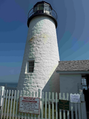
    This newsletter is going to highlight some history of the Coast and Geodetic Survey and provide the latest information on the National Geodetic Survey (NGS) new National Spatial Reference System (NSRS). First, every year my brother and I get together and travel to visit friends and relatives. He lives in Montana, and I live in North Carolina, so our yearly trips are typically 10 to 14 days long. As in all trips, I look for geodetic marks along the way. This year we traveled to coastal Maine to visit lighthouses and of course eat lobster rolls. We visited 12 Lighthouses along the Maine Coast. Lighthouses have both historical and navigational importance. The lighthouses were essential in guiding sailors through rocky shores. Portland Head Light commissioned by George Washington in 1791 is Maine’s oldest lighthouse and still guides vessels into Portland Harbor. We found NOS benchmark 841 8031 B 1979 on the grounds of this lighthouse. Pemaquid Point Lighthouse is managed by the Friends of Pemaquid Point Lighthouse, a chapter of the American Lighthouse Foundation, and remains an active aid to navigation under the ownership of the U.S. Coast Guard. We could climb up the Pemaquid Point Lighthouse, so I took a photo of the view from the top.

    Portland Head Light (Credit: Dave Zilkoski)
    Portland Head Light (Credit: Dave Zilkoski)

    One of my brother’s requests was to visit the first place in the continental United States to see the sunrise. However, the location of the first place in the continental United States to witness the sunrise depends on the time of year. As indicated in the box titled “First Places to See the Sunrise in the Continental U.S.” Mars Hill is the first place to witness the sunrise in June.

    Mark located on grounds of Portland Head Light. (Credit: Dave Zilkoski)
    841 8031 B 1979 — Mark located on grounds of Portland Head Light. (Credit: Dave Zilkoski)
    Pemaquid Point Lighthouse (Credit: Dave Zilkoski)
    Pemaquid Point Lighthouse (Credit: Dave Zilkoski)
    View from Pemaquid Point Lighthouse (Credit: Dave Zilkoski)
    View from Pemaquid Point Lighthouse (Credit: Dave Zilkoski)

    First Places to See the Sunrise in the Continental U.S.

    • October 7 to March 6: During these months, Cadillac Mountain in Acadia National Park, Maine, holds the distinction of being the first place in the continental U.S. to see the sunrise. Its elevation of 1,530 feet and eastern location make it ideal for early morning views. reddit.com+10nps.gov+10acadiamagic.com+10
    • March 25 to September 18: In the spring and summer, Mars Hill in Aroostook County, Maine, takes the title. Its northeastern position allows it to catch the first rays of sunlight during this period. newengland.com+2en.wikipedia.org+2aa.usno.navy.mil+2

    Around the Equinoxes: Approximately during the weeks surrounding the spring and fall equinoxes, West Quoddy Head in Lubec, Maine—the easternmost point of the contiguous U.S.—experiences the nation’s first sunrise. reddit.com+2en.wikipedia.org+2en.wikipedia.org+2


    That said, when we travel together, we always recover geodetic marks, so we chose to visit Cadillac Mountain even though in June the first place is located on Mars Hill in Aroostook County.  

    As many of you know, I worked for NGS for 35 years so reconning monuments is exciting to me. We found six marks in a radius of about two hundred meters on Cadillac Mountain. We will talk about them in a minute.

    Cadillac Mountain was important to me because from 1833 to 1898, the Coast and Geodetic Survey performed a triangulation project that extended from Calias, Maine, to New Orleans, Louisiana. The project was published as the Eastern Oblique Arc of the United States. The station Mount Desert 1856 that was located on Cadillac Mountain was part of this project. A report published in 1902 describes the Eastern Oblique Arc project and can be downloaded here.

    USCGS Special Publication Number 7. (Credit: USGS)
    USCGS Special Publication Number 7. (Credit: USGS)

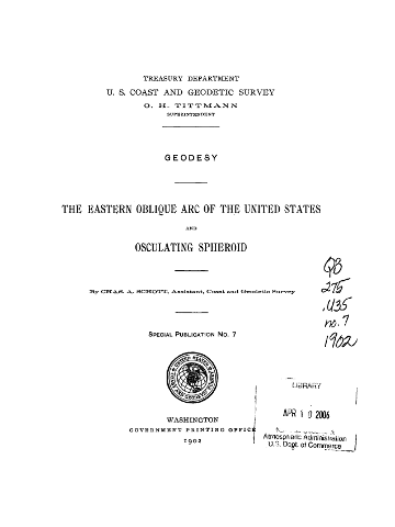
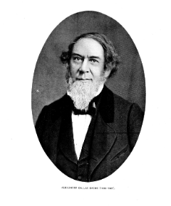
    According to the 1902 report, horizontal observations at station Mount Desert 1856 were acquired by Alexander Dallas Bache. That may not mean much to most people, but Mr. Bache was the second superintendent of the Coast Survey and was particularly important to the advancement of geodesy in the United States. As a side note, the Coast Survey was renamed the Coast and Geodetic Survey in 1878. The change reflected the agency’s expanded mission beyond coastal charting to include geodetic surveys of the nation’s interior, prompted by the growing importance of geodesy in its work.


    Bache’s leadership of the U.S. Coast Survey

    In 1843, Bache was appointed superintendent of the United States Coast Survey, succeeding Ferdinand Rudolph Hassler. Under his leadership, the Coast Survey expanded its missions to include hydrography, geodesy, topography, and the printing arts. He initiated geomagnetic studies, directed tide observers to make meteorological observations, and developed mathematical techniques for tide predictions and adjusting triangulation networks. Bache’s administrative skills transformed the Coast Survey into one of the foremost scientific organizations globally, providing critical data for navigation and commerce.

    Alexander Dallas Bache.
    Alexander Dallas Bache

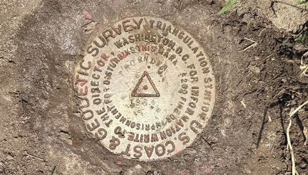
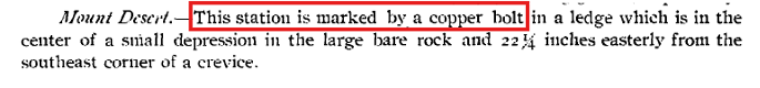
    According to the description of Mount Desert in the 1902 USCGS report, the station was marked by a copper bolt in a ledge (see the box titled “1856 Description of Mount Desert”). The 1902 description of the station on the NGS Datasheet stated that it was a hole drilled in a rock (see the box titled “1902 Description of Mount Desert”). I’m not sure why there is a discrepancy between the two descriptions but in 1931 the Maine Geodetic Survey found the drill hole, and based on measured references to other drill holes in the area that were documented in the original description decided that it was the location of the original station (see the box titled “1931 Description of Mount Desert”).  At that time, a Coast and Geodetic Survey Disk with Reference Marks were installed by the Maine Geodetic Survey.

    A description of Mount Desert from 1856. (Photo: NGS)
    A description of Mount Desert from 1856. (Photo: NGS)
    A Description of Mount Desert from 1902
    A description of Mount Desert from 1902.
    A description of Mount Desert from 1931.
    A description of Mount Desert from 1931.
    A description of Mount Desert from 1931.
    A description of Mount Desert from 1931.

    As I previously stated, we found six marks in the area. The boxes titled “Photos of Mount Desert 1856 and Reference Marks” and “Photos of Other Marks on Cadillac Mountain” provide photos of the monuments we found on Cadillac Mountain.  One may note that the reference mark 2 monument is in worse shape than the reference mark 1 and the Mount Desert monument. The 1944 recovery note stated that reference mark 2 was covered with roadway stone. There was not any stone covering reference mark 2 when I found it. Reference mark 1 is located behind some trees and out of sight of the path.

    When I arrived at the site, there were a group of people looking at reference mark 2. I held a little lecture on the importance of geodetic monuments and how this site was first occupied in 1856; and, of course, I highlighted the importance of geodesy.

    Photos of Mount Desert 1856 and reference marks. (Credit: Dave Zilkoski)
    Photos of Mount Desert 1856 and reference marks. (Credit: Dave Zilkoski)

    I was thrilled to stand in the very spot where Alexander Dallas Bache took geodetic measurements in 1856. [I know—people joke that I need to get a life, all because I get so fired up over geodetic monuments.]

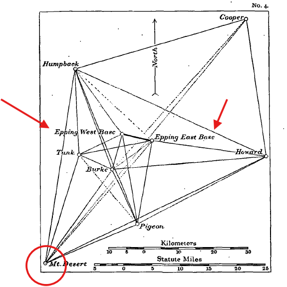
    The box titled “Abstract of Observations at Mount Desert” provides a summary of the directions from Mount Desert to the stations involved in this phase of the project. The box also includes a photo of an instrument, a 75 cm theodolite, which was used to perform the observations. The box titled “Diagram of Network Depicting Epping Base Line” provides a diagram that was included in the 1902 USCGS report.

    As a side note: during the 1970s as a NGS employee, I personally coded abstracts similar to this one to convert archival data into computer-readable form in support of the North American Datum of 1983 (NAD83) project. Once all data were in computer-readable form, they were reviewed for correctness and combined in an adjustment resulting in what is known as NAD 83 (1986).  See the NGS report for some details of the NAD 83 (1986) here.

    Abstract of Observations at Mount Desert (Credit: NGS)
    Abstract of Observations at Mount Desert (Credit: NGS)

    Diagram of network depicting Epping Base Line. (Credit: NGS)
    Diagram of network depicting Epping Base Line. (Credit: NGS)

    The other marks we found on Cadillac Mountain included a US Geological Survey Benchmark – K 24 1934, a bent pipe denoted as Cadillac Ground, and a Department of Interior Geological Mark – Cadillac 1975. All these marks are within a 200-meter radius of each other. My understanding is that Cadillac Ground was established because Mount Desert was obstructed by trees. I have provided weblinks for those that would like more information on these marks.

    Photos of other marks on Cadillac Mountain. From left to right, K 24 1934, Cadillac Ground and Cadillac 1975. (Credit: Dave Zilkoski)
    Photos of other marks on Cadillac Mountain. From left to right, K 24 1934, Cadillac Ground and Cadillac 1975. (Credit: Dave Zilkoski)

    After visiting more lighthouses along the Maine Coast, we traveled back to Boston and visited Waldon Pond and Thoreau’s family home. Why Thoreau you ask? In 2018, the Surveyors Historical Society and NSPS Foundation recognized Thoreau for his work as a surveyor by establishing a commemorative monument at Thoreau’s family farm.

    Thoreau described surveying as a “noble employment” that kept him close to nature: “Surveying … brings you within hearing of [the birds]” – https://www.heritagesurveys.com/famous-surveyors. Surveying and geodesy are indeed noble professions; they provide the foundation for all geospatial products and services.

    Photo of Commemorative Mark at Thoreau’s House. From left to right, Thoreau – A Surveyor, Thoreau Monument and drawing lines. (Credit: Dave Zilkoski)
    Photo of Commemorative Mark at Thoreau’s House. From left to right, Thoreau – A Surveyor, Thoreau Monument and drawing lines. (Credit: Dave Zilkoski)

    Finally, we left Boston for Syracuse to visit my younger brother and sister. I attended the SUNY College of Environmental Science and Forestry (SUNY ESF) which is immediately adjacent to Syracuse University campus. Both of my brothers attended Syracuse University, so we like to walk around campus whenever we visit Syracuse. During our trip to the University, we recovered the monument Thornden 1934. Thornden 1934 was significant to me because I recovered this monument over 50 years ago, as part of a special project that I performed for my geodesy class.

    Thornden 1934 (Credit: Dave Zilkoski)
    Thornden 1934 (Credit: Dave Zilkoski)

    I hope this was not too boring for you, but I real enjoy history and especially the history of the geodetic network of the United States. Today, you can use modern surveying technology to obtain a more accurate coordinate in seconds where it took days to months in the past. That is amazing!


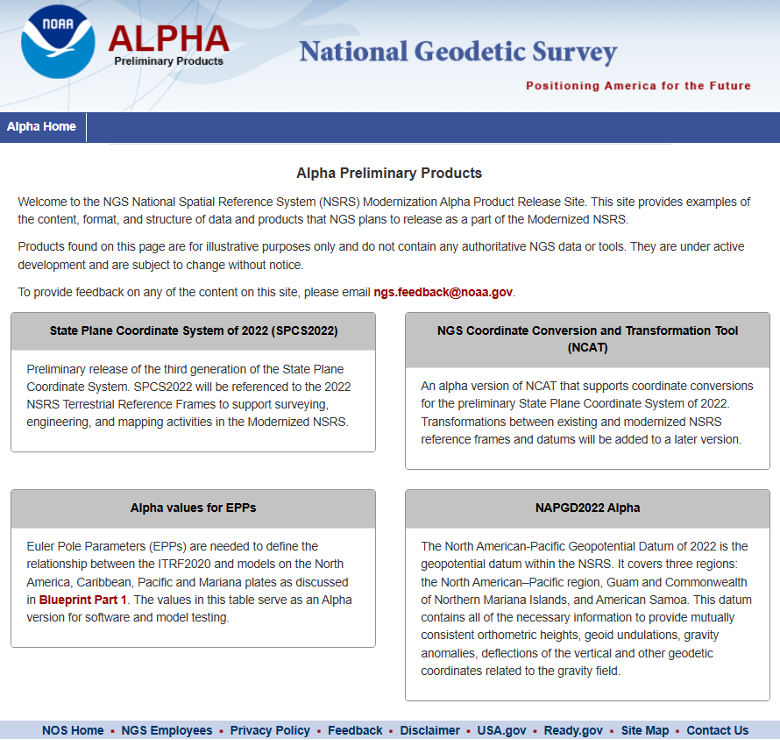
    Now, what is the latest with the modernization of the National Spatial Reference System? On June 17, NGS announced that they incorporated four groups of NSRS modernization products to the NGS beta website.

    Multiple NSRS Modernization Products Published to Beta

    NGS has released the following four groups of products to the NGS beta website to solicit review and feedback from stakeholders as part of the modernization of the National Spatial Reference System (NSRS): (Note: These products are not final and should not be used for anything other than review and testing.)

    North American-Pacific Geopotential Datum of 2022 (NAPGD2022). This datum will replace the North American Vertical Datum of 1988 (NAVD 88) and all other vertical datums for islands in the United States. It will serve as a foundational component of the modernized National Spatial Reference System (NSRS), providing precise definitions for orthometric height (elevation). The release includes the defining grids that collectively make up the datum along with a number of supporting products to visualize the datum.

    Products. All NAPGD2022 products are provided as grids for the following: GEOID2022, DEFLEC2022, GRAV2022.

    Example coordinates. Coordinates and product values are computed for numerous example points throughout NAPGD2022 and provided in a table. NAPGD2022 Experience. Interactive online maps showing NAPGD2022 products for all regions that can be used on a computer or mobile device to query any location.

    Maps of NAPGD2022 products. Static map images of NAPGD2022 products for all regions.New Terrestrial Reference Frames of 2022 for North America (NATRF2022), Pacific (PATRF2022), Caribbean (CATRF2022), and Mariana (MATRF2022) plates. These four geodetic reference frames will replace the North American Datum of 1983 (NAD 83). They will serve as a foundational component of the modernized NSRS, providing precise definitions for geodetic latitude, longitude, and ellipsoidal height.

    Euler Pole Parameters of 2022. All of the new terrestrial reference frames are defined by transformation from the International Terrestrial Reference Frame of 2020 (ITRF2020) using Euler Pole Parameters (EPPs) that model tectonic plate rotation.

    State Plane Coordinate System of 2022 (SPCS2022). A system of map projections for accessing the modernized NSRS. Zone designs have been incorporated into the following beta products and services:

    Zone information tables. SPCS2022 zone definitions, example coordinate computation results, minimum and maximum coordinate values, and minimum coordinate differences with overlapping SPCS2022 zones and with other coordinate systems, provided as interactive tables that can be sorted and filtered.

    SPCS2022 Experience. Interactive online maps showing distortion for all SPCS2022 zones that can be used on a computer or mobile device to get distortion at any location or to view zone definitions.

    Maps of SPCS2022 zones and distortion. Static map images of SPCS2022 zone layers, number of zones, and distortion with performance statistics.

    NGS Coordinate Conversion and Transformation Tool (NCAT). This version can be used to perform SPCS2022 coordinate conversions at any location for all SPCS2022 zones. Later beta versions will include the ability to transform between reference frames and vertical datums.

    Products found on the NGS beta website are preliminary releases that are for testing and evaluation only; they are not final products nor do they contain any authoritative NGS data or tools. To provide feedback on any of the content on this site, please email [email protected].


    Everyone should review these products and provide their feedback to NGS. That said, my April 2025 newsletter highlighted the NAPGD2022 Alpha product that was moved to the Beta site. The Beta product is like the Alpha product, but it does not have an option for an interactive computation. The Interactive Computation Option provided essential information about NAPGD2022 and would be helpful to geospatial users for obtaining a better understanding of the differences between NADGP2022 orthometric heights and NAVD 88, and GEOID2022 geoid heights and hybrid GEOID18 geoid heights. My April 2025 newsletter highlighted the interactive computation option.

    Alpha interactive computation page (Credit: NGS)
    Alpha interactive computation page (Credit: NGS)
    Alpha interactive computation page (Credit: NGS)

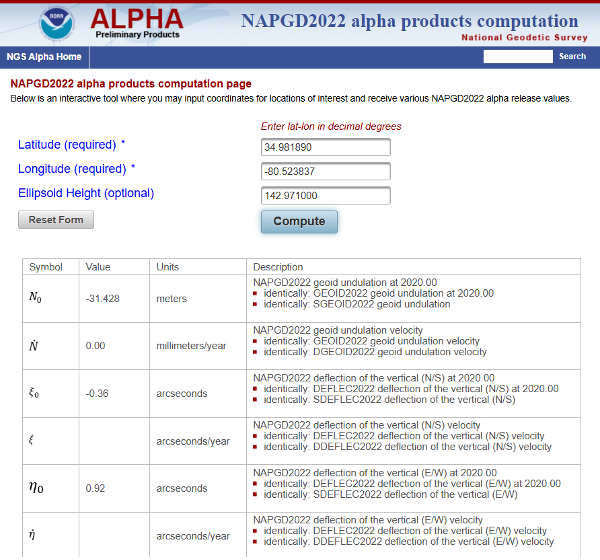
    As noted in my April 2025 newsletter, I downloaded the data and created my own maps to better highlight local variations. Although users can still view the original via the interactive online map, this personalized version offers clearer insights.

    Here are several of my comments on the Beta products based on my preliminary review:

    • The NAPGD2022 difference map (NAPGD2022 minus Historical in meters) uses 25 cm intervals, which are too coarse to reveal the finer local variations between published benchmarks accurately.
    • The NAPGD2022 Difference map should have an overlay of the marks used in the creation of the difference map. This would allow users to identify marks in their region of interest. Clicking on a mark should link to the NGS datasheet and Passive Mark Page.
    • The beta page for NATRF2022, PATRF2022, CATRF2022, and MATRF2022 is not particularly helpful for everyday geospatial users. There should be an Interactive Computation Option to enter NAD83 (2011), epoch 2010 coordinates where the routine transforms the coordinates into ITRF 2020, epoch 2020, as well as estimates in the new terrestrial reference frames – NATRF2022, CATRF2022, PATRF2022, and MATR2022.
    • Both the State Plane Coordinate System of 2022 (SPCS2022) and The NGS Coordinate Conversion and Transformation Tool (NCAT) are good tools for users to obtain an understanding of the differences and changes in the SPCS especially for their State. That said, like above, there should be an option to enter NAD83 (2011), epoch 2010 coordinates where the routine will transform the coordinates into ITRF 2020, epoch 2020, as well as estimates in the new terrestrial reference frames – NATRF2022, CATRF2022, PATRF2022, and MATR2022. The routine does have a note that states users can transform their coordinates using HTDP, but NGS should incorporate this process in the NCAT beta product.
      • Note from Beta NCAT product: This beta version of NCAT supports beta State Plane Coordinate System of 2022 (SPCS2022) but not transformations between reference frames or geopotential datums. NAD 83 latitude and longitude can be used as input, but the output coordinates will differ horizontally from actual SPCS2022 by up to a few meters, depending on location (likewise for UTM and USNG). If NAD 83 ellipsoid heights are used, the linear distortion and combined factor will differ from SPCS2022 values by a small amount, within ±0.3 parts per million (ppm). To reduce these differences, NAD83 epoch 2010.0 coordinates can first be transformed to ITRF2020 epoch 2020.0 using the Horizontal Time-Dependent Positioning (HTDP) tool.

    I plan to provide these comments to NGS through their feedback email process. Everyone should take time to review these products and provide your feedback to NGS. Remember, NGS placed these four groups of products on the NGS beta website to solicit review and feedback from stakeholders as part of the modernization of the National Spatial Reference System (NSRS) process. Users should review these Beta products and consider two questions:

    1. Do these products provide sufficient information and detail for documenting how I will deliver my products and services under the new NSRS?

    2. Do I need additional information or tools from the NGS to better understand the changes and impacts of the new NSRS?

    Your feedback will help NGS improve the Beta products.

  • BKZS: Türkiye’s regional GNSS system takes shape

    BKZS: Türkiye’s regional GNSS system takes shape

    Türkiye is laying the groundwork for its own satellite navigation system, the Bölgesel Konumlama ve Zamanlama Sistemi (BKZS), or Regional Positioning and Timing System. As a key pillar of Türkiye’s 2030 Industry and Technology Strategy, BKZS reflects the country’s ambition to gain strategic autonomy in satellite-based positioning, navigation and timing (PNT), moving away from dependence on foreign systems such as GPS.

    Strategic imperatives and security concerns

    BKZS was established as one of the ten flagship goals of Türkiye’s National Space Program, introduced in 2021. It directly addresses growing national security concerns: in times of geopolitical conflict, GNSS signals can be jammed or disabled — leaving nations vulnerable if reliant on foreign services. President Erdoğan’s 2030 roadmap emphasizes preparing for “a new era of challenges,” where technological independence is seen as vital to national sovereignty.

    Building the foundation: Atomic clocks and CubeSats

    At the core of BKZS development is innovative timing technology. The TUBITAK National Metrology Institute has designed Türkiye’s first domestically produced rubidium-based atomic clock for use in positioning satellites. Developed in collaboration with the Turkish Space Agency, the prototype is undergoing qualification testing. Considering that atomic clocks are among the most expensive and sensitive components of a GNSS system, their in-house development not only reduces reliance on foreign suppliers but also delivers significant cost savings and strengthens national expertise. The strategic plan involves an initial technology demonstration phase using a 6U CubeSat, a miniaturized satellite based on the CubeSat standard. This satellite — currently in production — will test the atomic clock in orbit and gather critical performance data, helping to validate system components and gain operational experience ahead of full deployment.

    Regional scope with global ambitions

    BKZS is being designed as a regional system focused on Türkiye and its surrounding geography. Preliminary architecture envisions an eight-satellite constellation with an estimated cost of $2.8 billion. While this figure underscores the program’s scale, it also reflects the strategic priority attached to securing sovereign PNT capabilities. Military users stand to gain the most immediate benefits, with access to secure, independent timing and positioning data. However, the system is also intended for broad civilian use, including smart transportation systems, precision agriculture, emergency response and disaster management.

    Integrated into a broader space strategy

    BKZS is not being developed in isolation. It is part of Türkiye’s wider National Space Program, which includes lunar exploration and autonomous launch capabilities. The Turkish Space Agency oversees coordination, while the Presidency of Defense Industries provides funding and logistical support. This ecosystem approach is designed to foster technological self-reliance across the entire space value chain. Notably, the private sector is also playing a role. Baykar’s space subsidiary, Fergani, is developing a complementary Turkish GNSS constellation with an ambitious plan to launch 100 satellites. Two of these satellites have already been built, with the first scheduled for launch in 2024, demonstrating multiple pathways toward achieving full domestic capability.

    Economic impact and industrial development

    BKZS also supports Türkiye’s economic goals. The 2030 Strategy includes a target to triple high-tech exports to $30 billion. Space technology is expected to contribute significantly to this goal by generating new opportunities for Turkish firms in satellite design, navigation electronics and advanced manufacturing.

    By fostering domestic expertise, BKZS strengthens the foundation for a sustainable, self-sufficient aerospace sector, one capable of supporting both defense and commercial applications.

    Aligning with a global trend

    Türkiye’s efforts echo a growing global trend: building regional or national GNSS systems to reduce reliance on global services. Reflecting this shift, India’s NavIC is a fully operational regional GNSS; Japan’s QZSS, also operational, functions primarily as a GPS augmentation system over the Asia-Pacific; South Korea’s KPS is currently under development to provide independent PNT services across the Korean Peninsula. China’s BeiDou system also began as a regional constellation focused on the Asia-Pacific before expanding to become a global navigation system. Türkiye’s geographic position — at the crossroads of Europe, Asia and the Middle East — positions it uniquely as a potential regional hub for satellite navigation services. While the project is rooted in national objectives, it also opens the door to international cooperation. Italy has emerged as a prospective partner, particularly in advancing space-qualified technologies, offering mutual benefits for both countries.

    Looking ahead

    Beyond 2030, TTürkiye envisions BKZS as a stepping stone toward a broader space infrastructure. This initiative signifies a strategic commitment to establishing a sustained and autonomous presence in space.

    Of course, the success of BKZS will depend on more than ambition. Sustained political commitment, reliable funding, and continued advances in core technologies like atomic clocks and satellite systems will be essential. If these conditions are met, BKZS has the potential not only to enhance Türkiye’s strategic autonomy but also to establish the country as a key contributor to regional — and potentially global — GNSS capability.

  • GPS World launches new digital opportunities and printing schedule

    GPS World launches new digital opportunities and printing schedule

    As GPS World marks its 35th anniversary, we continue to evolve to meet the needs of our valued subscribers and marketing partners. This month, we unveil strategic refinements to our magazine publishing schedule and our expanding digital content and solutions portfolio plans. 

    Tod McCloskey
    Tod McCloskey

    To better align with buying cycles and industry events, GPS World is transitioning from a monthly print and digital edition cadence to a six-times-per-year magazine frequency. Remaining 2025 issues are set for September and October. Beginning in 2026, GPS World issues will publish in February, March, May, June, September and October.

    Each GPS World issue will continue to deliver exclusive technical content and market insights. 

    In tandem with our magazine’s evolution, GPS World is significantly expanding its digital content and media solutions offerings, including:

    • Expanding GPSWorld.com: We will feature more exclusive content, delving deeper into today’s hottest trends in GNSS’ and complementary PNT’s top segments: autonomous solutions, defense, mobile, machine control/precision ag, simulators, surveying, mapping and transportation
    • New Custom Media Solutions: Leading technology suppliers now have an arsenal of platforms and offerings to educate our audiences on trends and advancements
    • Expanding Enews: Navigate Weekly!, Survey Scene, Autonomous Arena and Defense PNT e-newsletters: We will deliver even beefier segment news to your inbox each week 

    GPS World’s audiences are highly engaged confirmed buyers/specifiers. We promise to continue to evolve our integrated media offerings to meet readers’ and marketers’ changing preferences — because you are, and always have been, at the center of our information constellation.

  • Autonomous fighter drones join the front lines in USAF operations

    Autonomous fighter drones join the front lines in USAF operations

    The U.S. Air Force is increasingly referring to its next generation of unmanned aircraft as “fighter drones,” as the service prepares to integrate these vehicles alongside traditional fighter jets in combat missions. The Air Force’s Collaborative Combat Aircraft (CCA) program includes two separate vehicles under development by General Atomics Aeronautical Systems (GA-ASI) and Anduril, both designed to operate as combat-ready UAVs. These UAVs are being built to complement existing fighter fleets, providing additional capabilities and support during operations. According to Air Force officials, the new aircraft are expected to play a key role in future air combat by flying alongside piloted fighters and taking on a variety of tactical missions.

    One is an all-stealth design for undetected penetration of enemy defenses; the other is a sleek fighting companion.

    GA-ASI YFQ-42A fighter drone prototype (Credit: USAF)
    GA-ASI YFQ-42A fighter drone prototype (Credit: USAF)

    It appears the General Atomics YFQ-42A/CCA drew inspiration from the earlier stealth capabilities of the Avenger UAV, which has been in flight for more than a decade. This aircraft has a maximum ceiling of over 50,000 ft, flies at 400 mph, has around 15 hours of endurance and is powered by a built-in turbofan engine.

    Avenger UAV (Credit: GA-ASI/Tyson Rininger)
    Avenger UAV (Credit: GA-ASI/Tyson Rininger)

    One notable feature of the CCA version is its split, sloping “tailfin” and rounded design, along with a top fuselage air intake that shields the power plant from potential radar signals – all stealthy characteristics similar to those of its Avenger counterpart. Looking closely at the prototype, the doors on its belly appear to be for an internal weapons bay.

    Another USAF CCA prototype, built by Anduril, has been named the FYQ-44. It features a sleek and fast design, similar to earlier pre-stealth fighters, but also includes an internal weapons bay, rounded contours, and an air intake below the fuselage for a turbofan engine.

    Andruil YFQ-44 undergoes ground testing. (Credit: USAF)
    Anduril YFQ-44 undergoes ground testing. (Credit: USAF)

    The USAF’s release of these two CCA prototype contenders seems to suggest that they could be the fighter aircraft of the future. The CCA program, however, does talk about control of these armed UAVs by accompanying mainline manned fighter aircraft, but with autonomous capability to find and destroy once dispatched to attack a target.

    The intent is that these unmanned fighters will be significantly less costly to acquire than their expensive manned brothers so that high-risk targets may still be attacked and destroyed without potential loss of the flying pilot or their expensive aircraft. The unmanned fighters would be programmed by the manned aircraft and missiles in their internal weapons bay, would then go on to be controlled by onboard CCA weapons systems, which would relay data back continuously to the pilot who would have final go/no-go authority.

    Both prototypes are slated to fly later this year following extensive ground testing campaigns.


    After securing an initial $60 million contract from the USAF in 2021, Hermeus went on to raise $100 million in funding in 2022. This was followed by an investment from Raytheon Technologies’ RTX Ventures later that year. Additionally, the company landed a contract for Hypersonic risk reduction from the Defense Innovation Unit (DIU), allowing Hermeus to maintain its funding and momentum. This enabled the company to build and recently fly its first unmanned aircraft, which is designed to travel at extremely high speeds, according to the company.

    Hermeus Quarterhorse initial prototype UAV (Credit: Hermeus)
    Hermeus’ Quarterhorse initial prototype UAV (Credit: Hermeus)

    Initially, with an integrated GE J85 engine, Hermeus is now launching the incorporation of the Pratt & Whitney F-100 into its own “Chimera II turbine-based combined cycle (TBCC) propulsion system,” all aimed at taking subsequent iterations of their prototype to hypersonic speeds.

    Quaterhorse has been developed to demonstrate high-speed take-off and landing of a large unmanned aircraft, and is the first in a series of prototypes. And a couple of months ago, on May 27 at Edwards Air Force Base (AFB) in California, Quaterhorse did in fact take off, performed a short overhead circuit and landed! So, more flight tests are now expected to explore the drone’s flight characteristics.

    The TBCC two-phase engine with the Pratt F-100 front-end is slated to take Darkhorse, the next planned drone derivative, to Mach 2.8 on the F-100 and then up to over Mach 5 with the hypersonic back-end section of the engine. It could be said that the whole vehicle is being built around this monster engine!


    It will be interesting to see how flight testing of Quaterhorse progresses, but even more exciting to hopefully see if and when Hermeus gets the next hypersonic version flying. Additionally, we can anticipate the first flights of the USAF CCA prototypes.

    It is amazing how, from the humble beginnings of hobbyist radio-controlled recreational model aircraft, drones have evolved with sophisticated autopilots and are now becoming autonomous vehicles that are taking on front-line air force attack-support. Technological progress is now headed towards hypersonic capability.

  • A common language of location for emergency response: Survival in the ‘golden hour’

    A common language of location for emergency response: Survival in the ‘golden hour’

    NOTE: This article is adapted from an April 2025 U.S. National Grid Institute (USNGI) filing with the Federal Communications Commission (FCC) in response to an FCC Notice of Proposed Rulemaking on wireless location accuracy. The USNGI is a non-profit organization providing educational outreach and technical assistance to federal, state, local, and tribal governments, as well as commercial entities, to facilitate use of the USNG for a variety of purposes and, importantly, to support emergency responders in time critical situations (see usngi.org for more information).  — Jules McNeff, GPS World Editorial Advisory Board


    The term “golden hour” in medicine refers to the concept that rapid response is essential to improve chances of survival following a traumatic incident. Although the actual “golden” duration may vary, it encompasses the time required for incident detection and location, notification to the emergency call center, dispatch of responders, immediate triage and transport to an emergency medical facility. This timeline assumes that the incident location is clearly identified and effectively communicated to the call center and then to responders. Both the call center and the responders must also be educated in the use of geoaddresses. That is not always the case, and we are all familiar with situations where the location of responders was unclear or responders were misdirected, and victims died as a result.

    Since its inception, GPS has been described as providing a “common-grid coordinate system” for users. While well-meaning, this is incorrect, as it does not account for real “coordinate system” differences. In fact, GPS employs a common reference frame, which defines the shape of the Earth based on the latest realization of WGS-84 within the International Terrestrial Reference Frame. People may then superimpose different coordinate systems over the global reference frame for the purposes of positioning, navigation, surveying, geodesy and other applications. These diverse coordinate systems are the “languages of location” that can result in confusion and operational friction if their uses are not deconflicted upfront; the consequences of which can prove fatal in emergency response situations, as emphasized here.

    A Universal Language of Location

    The Federal Communications Commission (FCC) has been working for years to address these deficiencies through improvements to E-911 services, both for wireline and wireless networks.  Most recently, in March 2025, the FCC issued its (sixth) Notice of Proposed Rulemaking (NPRM) addressing wireless E911 location accuracy. In it, the FCC focused on requirements for more precisely determining three-dimensional locations, particularly the vertical component in structures. What is missing in this NPRM (and previous versions) is a clear understanding of the means to first identify the horizontal component of the incident location and report it to responders in unambiguous terms.

    That missing element is a definition of which “language of location” (reporting format) should be used to identify incident locations to responders. With access to current technologies such as GPS and complementary positioning sources, it is natural to focus on the precision of location technologies. However, it is equally important to address specifically how a defined location is then reported to the responders who must locate it once they are dispatched. Modern technology can deliver precise three-dimensional locations, but the emphasis for responders must first be on understanding the horizontal component. If they do not arrive at the right horizontal geoaddress due to location reporting confusion, then the vertical component, even if it is relevant, does not matter.

    The most common reporting format in urban and suburban areas is, of course, the street address.  However, even within developed metropolitan areas, street addresses are not always consistent or definitive. In disaster situations, they may not even be present due to wind, flooding, fire or other physical destruction. They are also not useful in rural and remote areas away from established infrastructure. Another common format is latitude and longitude (lat/lon), which the public is aware of but not familiar with in terms of describing a specific location. Additionally, the use of lat/lon is complicated by the fact that it is a spherical system, and a location may be identified in any one of three different lat/lon versions, depending on how degrees, minutes and seconds are combined. Using the wrong version can lead responders far astray, resulting in lives lost. Other formats are available, but many are proprietary, difficult to understand, unfamiliar to the public and/or, most importantly, not directly available from proven position determination technologies such as GPS.

    USNGI Presents a Solution

    In its filing, the USNGI advocates that the FCC direct wireless communications providers to replace all references to civic (street) addresses and to latitude and longitude in reporting the horizontal component of incident locations with the term “U.S. National Grid (USNG) geoaddress.” It also recommends that the FCC consider rules under consideration that direct wireless providers to display USNG coordinates for horizontal addressing, using z-axis elevations provided by other technologies.

    The USNG is a publicly available Federal Standard (FGDC-STD-011-2001) established in 2001 by the Federal Geographic Data Committee (FGDC) as a nationally consistent grid reference system and the preferred grid for National Spatial Data Infrastructure (NSDI) applications. The USNG creates horizontal geoaddresses that are unique, much easier to understand than latitude and longitude and always identifiable because they are referenced to a global grid and not to local features. In a simple format, the size of a telephone number, the USNG can define locations today to an accuracy of 10 m, far exceeding the 50 m requirement in the proposed rulemaking.

    As noted above, USNG geoaddresses provide a clear and unambiguous way to describe locations in areas away from established road networks, or those affected by a natural disaster, where road signs have been destroyed. To make their use by the general public and emergency responders even easier, a variety of free smartphone applications are available today that provide continuous USNG geo-locations when activated.

    An object lesson is provided by one example (of many throughout the country), the drowning of a teenager named Fitz Thomas on the Virginia side of the Potomac River on June 4, 2020. This tragedy drew much local and even national attention. The teen was swimming at a small creek with friends in a park adjacent to a development, but without a street address. When he got in trouble, his friends tried to help and then called 911 on their cell phones, but could not describe their specific location. Because of the location confusion, coupled with jurisdictional failures, Fitz Thomas could not be saved. If the frightened teens had only been aware of, or had been asked/told by the 911 call center to give the center their geoaddress (which they could have gotten on their cell phones), all uncertainty about the incident location would have vanished immediately, and response could have been dispatched in the instant.  The graphic shows the area with a 10 m USNG geoaddress, but which the group was not aware of at the time. The short geoaddress they needed was: TJ 8570 3094.

    The location on the Virginia side of the Potomac River where Fitz Thomas tragically drowned on June 4, 2020.
    The location on the Virginia side of the Potomac River where Fitz Thomas tragically drowned on June 4, 2020.

    Real-World Applications

    USNG geoaddressing has been adopted by many federal agencies and by several state and local governments to facilitate emergency response operations:

    • The Federal Radionavigation Plan (FRP): The FRP, signed by the Secretaries of Defense, Transportation, and Homeland Security, states in Section 1.7.8 (Interoperable U.S. National Grid for Emergency Response Operations) that “…public availability of location-based applications in mobile electronic devices has highlighted the need to create awareness in the USG and among the public of a standard means to identify accident and other incident locations for emergency response purposes. Lack of a uniform method for describing incident locations has been a major impediment to rapid and effective emergency response in diverse metropolitan and rural areas.”  It identifies the objective of the USNG standard “…to increase interoperability of location-based services by establishing a nationally consistent and preferred grid reference system to enable user friendly position referencing on gridded paper and digital maps in combination with GPS receivers and Internet map portals.” 
    • The National Search and Rescue (SAR) Committee (NSARC): The NSARC designated the USNG as a preferred land search & rescue coordinate system in 2011.  NSARC manuals specify use of the USNG as the primary georeferencing system for land SAR operations and for air-land SAR coordination. This aligns with coordination of military/civil responder operations as noted below.
    • The Federal Emergency Management Agency (FEMA): In October 2015, FEMA issued FEMA Directive 092-5, titled “Use of the United States National Grid (USNG),” which states as FEMA policy that, “FEMA will use the United States National Grid (USNG) as its standard geographic reference system for land-based operations and will encourage use of the USNG among whole community partners. FEMA will reference and employ the USNG in doctrine, relevant preparedness and grant programs, deliberate and crisis-action planning, training, exercises, operations, logistics, and other appropriate disciplines.”
    • Urban Search and Rescue (USAR): FEMA USAR teams adopted the USNG as a response to lessons learned during Hurricane Katrina and subsequently have deployed using the USNG in various disaster response operations.  Also, during the aftermath of Hurricane Katrina and others, Delta State University in Mississippi produced a wide variety of map products incorporating the USNG to assist federal and state emergency responders.

    In his statement relative to the proposed rulemaking, Chairman Carr noted a visit to Fire Station 40 in Fairfax County, Virginia.  That is the home station for Virginia’s FEMA USAR Task Force 1, a world-renowned rescue team and early adopter of the USNG.  The firefighters he met with that day may well have mentioned their use of the USNG in describing to him how location technology assists in the execution of their missions.

    • The DHS National Incident Management System (NIMS): The DHS NIMS identifies the USNG as “… a point and area location reference system that FEMA and other incident management organizations use as an alternative to latitude/longitude. The National Grid is simple to apply to support risk assessment, planning, response, and recovery operations. Individuals, public agencies, voluntary organizations, and commercial enterprises can use the National Grid within and across diverse geographic areas and disciplines. The use of the National Grid promotes consistent situational awareness across all levels of government, disciplines, threats, and hazards, regardless of an individual or program’s role.”
    • Joint Military/Civil Emergency Response Operations:  As noted in the FRP, “The USNG is the civilian version of the Military Grid Reference System (MGRS) that the military uses for tactical operations. It enables geolocating incident locations from 100m to 1m precision.” A Chairman of the Joint Chiefs of Staff Instruction (CJCSI 3900.01E) on georeferencing states that, “To support homeland security and homeland defense, the USNG standard is operationally equivalent to MGRS.” As with the MGRS, the USNG is easy to learn by all levels of personnel, it is interoperable if used by civil and military first responders, it improves military support to civil authorities, and very importantly, it reduces operational friction and facilitates crisis and disaster response at all levels from federal to local government.
    • Emergency Location Markers (ELM): Localities in Minnesota, Georgia, Florida and other communities across the U.S., including National Parks, and even the Kennedy Space Center, have installed USNG-based ELM to give trail and park users a way to report an emergency location. Due to the disparate physical locations involved, nearly all such incident reporting can be expected to come from wireless systems, but to be enabled by reception of GPS positioning signals. The graphics below show the ELM relationship to GPS and how the reporting is facilitated by use of the USNG.
    the ELM relationship to GPS and how the reporting is facilitated by use of the USNG.
    The ELM relationship to GPS and how the reporting is facilitated by use of the USNG.
  • EAB Q&A: Urgent actions needed to protect resilient PNT amid spectrum sharing and GNSS policy shifts

    EAB Q&A: Urgent actions needed to protect resilient PNT amid spectrum sharing and GNSS policy shifts

    What urgent policy or industry actions are needed to protect and advance resilient PNT services amid spectrum sharing debates and GNSS regulation changes?

    Headshot: Jules McNeff
    Jules McNeff, vice president, strategy & programs, Overlook Systems Technologies

    In my article, “Is There a Silver Bullet for Resilient PNT?”, I addressed the confusion caused by the numerous and diverse industry initiatives now being offered. Industry is understandably motivated to provide resilient PNT capabilities, but each also wants the government to pick its solution and make policy decisions accordingly. Spectrum sharing decisions that favor a single service provider may harm others in a crowded space, and so are difficult or impractical, as we have seen with the decades of litigation associated with LightSquared/Ligado and the spectrum surrounding the GPS L1 frequency. 

    Not everyone can win that competition, and as I noted at the end of the article, “Unless our government accepts responsibility, there will be no PNT silver bullet for domestic CI. Experience shows that industry will not solve this problem alone.”

    For years, I have advocated that U.S. PNT technology policy be managed and services acquired holistically as vital dual-use civil/military capabilities. For the civilian community, that means making sure the national leadership understands the reliance our domestic critical infrastructure (CI) has on constant access to precise PNT to maintain continuity of operations across all CI sectors in the face of well-known threats.  The leadership must then decide whether that reliance deserves proactive attention by the government to ensure PNT continuity is not disrupted.

    Several years ago, I suggested that significant regulatory changes were needed in how civil PNT services were handled throughout U.S. CI. Both the Departments of Homeland Security and Transportation were assigned responsibility in Presidential Directives for finding a GPS backup to PNT services in domestic CI. I won’t revisit that years-long debate (which is still unsolved), but I will revive the framework of the suggestion.

    The DOT has overall responsibility for civil agency PNT matters, and DHS frequently cites lack of regulatory authority as a limitation on its ability to encourage compliance in the CI sectors for which it is responsible. Therefore, I suggested that the National Space-Based PNT Executive Committee consider regulatory changes to expand the definition of the Transportation CI Sector to include safe and uninterrupted transportation of all elements contributing to domestic critical infrastructure.  In addition to current air, road, rail, and oil/gas pipeline transportation, add the interstate transport of information (Communications and IT), electrical energy (Power Grids), economic transactions (Finance), crops (Agriculture), and water, as well as domestic maritime services (U.S. Coast Guard) and possibly emergency response services in the case of large disasters. 

    In the spirit of the former Interstate Commerce Commission, which years ago was replaced by a DOT Surface Transportation Board (primarily concerned with freight rail), the DOT may then seek expansions to STB authorities and membership to address the PNT dependencies and vulnerabilities affecting those fundamentally transportation-oriented activities vital to the viability of all U.S. critical infrastructure sectors.

    — Jules McNeff
    Overlook Systems Technologies

    Headshot: Miguel Amor
    Miguel Amor, chief marketing officer, Hexagon’s Autonomy & Positioning Division

    Regulatory authorities must quickly approve and protect RF spectrum allocated for new PNT capabilities, particularly for emerging low-Earth orbit (LEO) constellations. These systems offer clear advantages in signal strength, geometric diversity and resilience against jamming and spoofing. Without timely and well-defined spectrum authorization, along with strong adjacent-band protections, the deployment of GNSS receivers capable of supporting these constellations will be delayed.

    On the industry side, LEO PNT developers must urgently finalize signal structures and release Interface Control Documents, enabling GNSS receiver manufacturers to begin implementation, validation and system integration.

    — Miguel Amor
    Hexagon Positioning Intelligence

    Mitch Narins
    Mitch Narins, Strategic Synergies

    Interesting and timely question.  I’ve written quite a few pieces and papers on the need for resilient and robust PNT services.  If I were to point to a single thing that has held the US (and many other countries in the world back (except for China) it is lack of strong mission-oriented, dedicated leadership.  It has been said that the definition of a committee is an entity with four or more legs and no brain. It is time to designate a single entity and a single office and a single person as responsible for ensuring resilient PNT services to US critical infrastructure so as to maintain the safety and security and economic benefits these these sectors support.  Some wise men once came up with the idea that a government must “provide for the common defense” and “support the general welfare.” Resilient PNT is essential to achieving both.

    In addition to the lack of empowered, centralized PNT leadership, a key problem that has impeded progress towards resilient PNT is the lingering belief by many that given enough time and money and spectrum, GNSS-sole means is achievable and that all non-GNSS systems (affectionately called “Legacy PNT Systems”) can be discontinued. In fact, over the years budget justifications for GNSS systems have used discontinuance of ground-based systems as “a benefit” to balance out the costs of establishing, updating, and operating GNSS.

    Engineering System Designer should never fall in love with their solutions.  The mission, i.e., the needs of the customers must always remain their first concern.  After many years, integrity was added to the list of PNT metrics; coverage has yet to be officially added. Yet, even today, there remains confusion regarding the availability metric and the associated risks.  For GNSS systems, the risk of losing required PNT metrics should always be considered “1.0”, and therefore, for critical infrastructure users and providers, require effective and implementable contingency/continuity of operation plans.  Loss of PNT performance (accuracy, availability, integrity, continuity, and coverage) the using GNSS can no longer be considered a “Black Swan” event.

    — Mitch Narins
    Strategic Synergies


    In the February 2025, Professor Washington Ochieng proposed the following question to the GPS World EAB.

    When we discuss the security of GNSS/PNT systems, we nearly always focus on interference — i.e., meaconing, intrusion, jamming or spoofing. However, GNSS/PNT systems are embedded in systems of systems that also offer many other opportunities for cyberattacks. What should we do about it?

    I have thought for some time about why this is an issue.  This is an interesting question, and the answer should be straightforward – but it’s not.  For whatever reason, it seems many in the “cyber community” believe they are different, somehow, and apart.  This has been apparent to me in dealing with those in the cyber community regarding their PNT dependencies and vulnerabilities going back to the creation of USCYBERCOM as a separate combatant command within the DoD.  Those in the cyber world seemingly do not see a need to recognize and account for the intersection of PNT and cyber as mutually integral parts of a broader Information Technology ecosystem.  Yet, across that entire IT ecosystem, PNT is simultaneously an enabler and a product of IT functionality, as communications and data systems could not operate without it, and it is likewise vital to IT users in executing their diverse missions.  Ultimately, interference effects, whether from jamming or spoofing in their various forms or from digital intrusions of one kind or another, disrupt vital elements of that IT ecosystem.  Our national and economic security depend on the continuous, reliable, uncorrupted functioning of IT services enabled by and delivering PNT information. So, a straightforward but difficult to implement answer is that we need formal education programs to routinely inform the leaders of industry and government (and the public) of the ubiquitous, vital role of positioning and timing (what we call PNT) throughout all the systems-of-systems whose operation depends on the IT ecosystem – and how to tell if something is amiss.

    — Jules McNeff
    Overlook Systems Technologies

    Read more responses to Professor Ochieng’s question.

  • Evaluating your constraints in a GNNS network adjustment

    Evaluating your constraints in a GNNS network adjustment

    My previous newsletter highlighted a National Geodetic Survey (NGS) webinar held on April 25, 2025, titled “Design of Networks Using NOS NGS 92,” given by Dave Zenk, NGS northern plains regional advisory.

    [Authors note: Dave Zenk told me that he is retiring from the National Geodetic Survey on May 31, 2025. Dave’s presence will be deeply missed. His dedication and spirit have left a lasting impact on NGS’s products and services. I hope his retirement is filled with joy, relaxation, and new adventures.] 

    In addition to Dave Zenk’s retirement, several other NGS Regional Geodetic Advisers have retired or left NGS employment over the past several months. Click here for a list of the current advisors, along with the names of interim contacts handling inquiries for those advisors who have retired or departed from government service.

    As previously mentioned, Dave showed a well-presented outline of the tables that users need to be familiar with when using OPUS Projects to process and submit GNSS projects to NGS for publication. It should be noted that users submitting data to NGS must follow the guidelines outlined in NOS NGS 92.

    I found the webinar to be very informative, and I would encourage all users of OPUS Projects to download the presentation. During the webinar, Zenk briefly mentioned three items that I believe deserve more explanation for anyone using OPUS Project. This newsletter will address the following topics in more detail:

    • The mark’s classification — primary, secondary, and local — will not be included on the NGS datasheet, but the local and network accuracy from the project will be provided on the datasheet. What does this mean to someone who’s using the mark in their project?
    • OPUS Project uses the F-statistic test to determine if the appropriate constraints were imposed during the horizontally and vertically constrained adjustments. Why does OPUS Project use this statistic?
    • The Constraint Ratio (CR) test, computed by OPUS Projects, provides a method for identifying which coordinates should be constrained and which should not be considered for constraints in the final horizontally and vertically constrained adjustments. What’s the best way to use this table?

    First, the presentation discussed the tables that described the procedures for establishing three different mark classifications — primary, secondary and local. It also mentioned that the classification will not be included on the NGS datasheet but the local and network accuracy from the project will be provided on the datasheet. See the image below.

    Photo:
    Photo: NGS website

     What does this mean to someone who’s using the mark in their project? Since the NGS data sheet will provide the network and local accuracy from the project, users can determine if the accuracy value of the mark meets the requirements of their project. In my opinion, the network and local accuracy from the project provide a better indication and understanding of the level of trust of the published coordinate.

    As previously mentioned, anyone submitting a GNSS project to NGS for publication must adhere to the NOS NGS 92 guidelines. During the presentation, Zenk provided several examples that depicted correct network designs. I would encourage everyone to download the NOS NGS 92 document and Zenk’s presentation to gain an understanding of the classifications and the network design requirements to meet a particular classification.

    Photo: NGS website
    Adhere to NOS NGS 92 guidelines (Photo: NGS website)

    Anyone who submits an OPUS Project to NGS for publication knows that the constrained adjustments must meet the requirements of the F-statistic test. So, what is this test, and why does OPUS Project require this statistic? Essentially, it is a method of verifying whether the appropriate constraints were applied during the horizontally and vertically constrained adjustments. The F-test evaluates the ratio of two variances; that is,

    Photo:

    The F-test checks whether this ratio is significantly different from 1, which would suggest the models have significantly different fits to the data. The result is compared against the critical value from the F-distribution based on the degrees of freedom from the constrained adjustment and the degrees of freedom from the minimally constrained adjustment, and a chosen significance level alpha (e.g., 0.01).  NGS OPUS Project uses an alpha level of 0.01% or 99% confidence level.

    Photo:
    Definition of the F-test (Photo: Wikipedia)

     
    The following is an excerpt on the F-test from NGS’s Online OPUS Project Guide  – (Section 12.7.3.2. Analyzing the Horizontal Constrained Adjustment):

    Once the adjustment has been deemed acceptable i.e. all shifts and residuals are reasonable, the F-test should pass. The F-test is a statistical test that helps determine if the variance (variance of unit weight) from a fully constrained adjustment is significantly different from the variance (variance of unit weight) of a minimally constrained adjustment. The variance of unit weight is a critical statistic and should be looked at carefully when evaluating adjustment results. If the fully constrained adjustment fits well with all selected control (the constraints), the value of the variance of unit weight should be close to 1.0. The F-test is performed using a 99% confidence level.

    So, if the constrained adjustment statistics differ significantly from the minimally constrained adjustment, then there could be an issue with the constraints.  Of course, this is assuming that the minimally constrained adjustment variance of unit weight indicates that all data outliers have been eliminated.  So, why are constraints important?

    OPUS Project first calculates GNSS coordinates in a minimally (free) network adjustment, which defines relative positions but not their absolute placement in space.  Without constraints the entire network can float and/or rotate.

    Constraints are important in GNSS network adjustments because they:

    • Anchor the network in a geodetic datum; in this case, NAD 83 (2011), epoch 2010.0.
    • Ensure a unique and stable solution that reflects the physical world.
    • Make the network useful for engineering, mapping, and scientific purposes.

    Control point coordinates (from previous surveys or known datums) often have inherent errors or uncertainty. Constraining coordinates exactly assumes zero error, which is rarely true.   Weighted constraints let you assign a realistic level of trust to known published coordinates by using error estimates. OPUS Project applies weighted constraints based on input error estimates (OPUS Project denotes these as sigmas of the coordinates), which allow for minor deviations in the constrained coordinates. The weighted constraint methodology provides flexibility to network adjustments by recognizing that published coordinates have some uncertainties and allows constraints to take on small corrections leading to more accurate and consistent network solutions. Although, it should be noted that the adjusted coordinates of the constraints from the final horizontally constrained adjustment are not updated in the NGS database even though there are minor deviations to their final adjusted values.

    After performing a least squares adjustment using the weighted constraints, the F-test helps to ensure that the appropriate coordinates are constrained with the appropriate error estimates. The following is an excerpt from the OPUS Project Online User Guide – (Section 12.7.3.2. Analyzing the Horizontal Constrained Adjustment):

    If the F-test fails, it is due either to the errors (sigmas) of the constraints being overly optimistic (too small) or the constrained coordinates not agreeing with the observations (causing excessively large shifts of the constrained coordinates). Failure of the F-test does not automatically mean the constrained adjustment is bad. It is a flag that indicates there may be a problem with the constraints, and that they should be investigated. In addition, the F-test assumes of a normal (“bell-shaped”) probability distribution of the residuals. Networks with a distribution that is significantly non-normal may fail for that reason, even when a constrained adjustment is acceptable.

    if your adjustment fails the F-test, what do you do?  How do you determine which constraint or constraints should be unconstrained?  OPUS Project provides some information about the constraints that can be helpful in determining a bad constraint.  The CR test, computed by OPUS Projects, provides a method for identifying which coordinates should be constrained and which should not be considered for constraints in the final horizontally and vertically constrained adjustments.  What’s the best way to use this table?  The box titled “Constraint Ratio” from NGS’s Online OPUS Project User Guide — (Section 12.7.3.2. Analyzing the Horizontal Constrained Adjustment) provides a good explanation with an example of using the constraint ratio table (12.7.3.2. Analyzing the Horizontal Constrained Adjustment).  Basically, this statistic highlights coordinate shifts that are significantly larger than expected based on the sigma provided by the user.  That is, coordinates that have a very small sigma should not be expected to change as much as coordinates with a very large sigma.  The CR value is compared to a critical value of 3.0, which corresponds to a t-statistic at the 99% confidence level.  Therefore, any constraint ratios greater than three should be investigated and are candidates to be unconstrained (see the box titled “Constraint Ratio”).


    Constraint Ratio

    If the F-test fails, it is possible that some constraints need to be freed up. It might be the case where some of the shifts are too large. The CR test provides a way of identifying where the bad shift might be. The CR is essentially a Students T Test, with the absolute value of the shift between the adjusted, constrained coordinates and the published coordinates, divided by the sigma (σ, or standard deviation) used to constrain the station. It is computed for each component (north, east, and height):

    Photo:

    OP provides the CR for all marks in the final table in the output summary given in the body of the email or in the Processing Report (.txt), as shown below in Fig. 12.21.

    Fig. 12.21 Constraint Ratio Test as seen in the Processing Report of the Horizontal Constrained Adjustment. (Photo: NGS)
    Fig. 12.21 Constraint Ratio Test as seen in the Processing Report of the Horizontal Constrained Adjustment. (Photo: NGS)

    Computed CRs are compared to the critical value or 3.0, corresponding to a T-statistic at a 99% confidence level. If the value of CR is greater than 3.0 for any of the three components, that indicates that there may be a problem with the constrained station.


    I find these statistics very helpful when determining which coordinates should be constrained in the final adjustments.  I hear that some users select all possible constraints and then start releasing marks based on the CR table.  That certainly is one way of doing it but could be time-consuming and confusing.  That said, the first thing I do is compare the minimally constrained adjusted coordinates to the published coordinates to determine if there are any obvious outliers.    This has been helpful to me in large GNSS projects located in subsidence regions such as the Harris-Galveston, Texas, region of the United States.

    One final note on OPUS Project

    On May 22, 2025, NGS issued a notice to users, announcing the implementation of the International Terrestrial Reference Frame 2020 (ITRF2020).  The announcement provided the following information addressed to all Active OPUS Project Users.

    Active OPUS-Projects Users,

    In early June, NGS will implement the new International Terrestrial Reference Frame 2020 (ITRF2020) and IGS20 realizations in the U.S. National Spatial Reference System (NSRS) in order to maintain consistency with the International Earth Rotation and Reference System Service (IERS) and the International GNSS Service (IGS) reference frames. This results in updated North American Datum 1983 (NAD 83) coordinates for stations in the NOAA CORS Network (NCN), kept at epoch 2010.0. This update is called the Multi-Year CORS Solution 3 (MYCS3), and it follows NGS’s MYCS2 effort from 2018.

    OPUS-Projects users with active projects are advised that open projects will need to be reprocessed from the beginning in ITRF2020. 

    If projects are close to completion, users have the option of submitting them to NGS before the transition using the currently published NAD83(2011/MA11/PA11) coordinates transformed from ITRF2014. The deadline for submissions is June 6, 2025 for those wishing to take this route.

    If you have questions, please contact [email protected].

    Above, I bolded several sentences that will be important to users currently performing projects using OPUS Projects.  That is, all projects not submitted by June 6, 2025, will need to be reprocessed from the beginning in ITRF2020.  

    Users should continue to check NGS’s website for announcements regarding the transition from the alpha site to the beta site. Future newsletters will address the Multi-Year CORS Solution 3 (MYCS3) and will highlight the beta products as they are released.

  • FCC opens door to GPS alternatives, but risks undermining its greatest strength

    FCC opens door to GPS alternatives, but risks undermining its greatest strength

    On March 27, the Federal Communications Commission (FCC) unanimously approved a Notice of Inquiry (NOI) to explore GPS alternatives, amid escalating threats to security and system resiliency. The move signals growing federal concern about the reliability of space-based navigation and timing infrastructure amid rising global interference and spoofing incidents.

    But while the FCC’s broad consideration of alternative technologies is a welcome step forward, its framing also risks weakening one of GPS’s most important defenses: the growing adoption of multi-constellation strategies across the commercial sector.

    Rising Threats, Broader Mandates

    The FCC’s decision follows the release of the International Air Transport Association’s (IATA) latest safety report, which documented a 175% increase in GPS interference and a 500% rise in spoofing attacks year-over-year. These incidents pose critical challenges to aviation safety, emergency services, telecommunications, and countless other sectors that rely on Positioning, Navigation, and Timing (PNT) services.

    Against this backdrop, the Commission’s vote reflects a bipartisan sense of urgency. The NOI invites public comment on a range of technologies that could serve as complements or alternatives to GPS, including low-Earth orbit (LEO) satellites, terrestrial signals, and enhanced end-user devices. This broad framing is encouraging and acknowledges the multifaceted nature of PNT resilience.

    A Multi-Layered Approach to PNT

    The FCC’s focus on diversification — across space-based, terrestrial, and user-level technologies — is not only prudent, but essential. Enhancing national security and system redundancy requires more than a single backup solution. It demands layered resiliency that integrates complementary modalities into a cohesive ecosystem.

    It is very encouraging that the NOI outlines a wide array of candidate technologies that could play a role in improving the U.S. PNT infrastructure. These range from inertial navigation systems and time transfer services to novel terrestrial radio signals and commercial LEO constellations. By casting a wide net, the FCC opens the door to innovation and allows market forces to contribute meaningfully to PNT modernization.

    Commercial Reality vs. Government Narrative

    However, the FCC’s discussion notably underplays a key reality: few commercial technologies today rely solely on GPS. The commercial PNT landscape has already moved beyond single-source dependency, with the vast majority of systems integrating multiple GNSS constellations (such as GPS, Galileo, BeiDou and GLONASS) alongside additional sensor and signal data to ensure robust coverage and accuracy.

    This multi-constellation approach is arguably the single most powerful tool we have to strengthen the resilience of GPS-dependent systems. By allowing receivers to pull data from multiple GNSS sources, users gain spatial and signal diversity, enabling them to cross-check signals, reject spoofed or erroneous data, and maintain accurate position and timing even in degraded environments. It’s important to remember that a device can’t selectively use GNSS networks depending on the user’s geography. If U.S. device makers disable BeiDou and GLONASS, then anywhere in the world that receiver goes it will be less performant and competitive. In recent field tests, we found that disabling the BeiDou constellation decreased a device’s positioning accuracy by 30% to 40%.

    This accuracy and resilience are especially important in sectors like aviation, autonomous systems, and emergency response, where signal fidelity and redundancy can be life-saving. Multi-constellation GNSS use isn’t theoretical: it’s already the industry standard.

    The International Tightrope

    Despite this, key elements of the NOI, as well as comments during the meeting, reflect a growing U.S. government skepticism toward the inclusion of foreign GNSS systems, especially BeiDou and GLONASS. While geopolitical caution is understandable, overly rigid restrictions on international signals could do more harm than good.

    These systems are not merely foreign-owned alternatives. They are integral components of the modern GNSS environment. Many U.S. commercial devices — ranging from smartphones to augmented reality, fleet tracking systems, drones, and more — already leverage multiple GNSS sources by default. Future technologies such as autonomous vehicles, robotics and urban air mobility will also require multiple GNSS signals to function. Prohibiting or restricting their use could mean rolling back years of progress in signal resilience, not to mention stymying future technologies, and all for a speculative and largely unquantified national security risk.

    While there are some valid concerns about adversarial control over PNT infrastructure, the FCC must weigh these carefully against the real, measurable benefits of an open and interoperable GNSS ecosystem. An overcorrection risks introducing new vulnerabilities in the name of mitigating others. In reality, the more vulnerable elements of the threat surface are GNSS receivers and mobile networks, particularly 5G systems, where user location is actually determined and tracked. Unlike the largely speculative and technically unproven threats tied to adversarial GNSS constellations, there are well-documented cases of compromised receivers and nation-state exploitation of mobile infrastructure – the very reason several countries have banned Chinese 5G providers. The FCC should focus on these clear and active risks, rather than reacting to theoretical scenarios that experts argue are not technically feasible.

    Innovation at Risk

    There is a significant opportunity at this moment. The NOI rightly identifies emerging technologies that can enhance U.S. resiliency, including advanced chipsets, LEO-based positioning, crowd-sourced signal verification, and next-generation timekeeping tools.

    However, that innovation cannot thrive in isolation. If the U.S. limits the ability of domestic systems to take full advantage of all available GNSS sources, it will undermine both resiliency and competitiveness. Even worse, it could widen the gap with foreign alternatives, especially China’s BeiDou system, which is already surpassing GPS in both accuracy and global coverage. GNSS has always thrived on multi-national cooperation and the opportunity of soft power influence. Both of which are diminished by exclusion, which is likely why there have not been bans by other countries to date.

    A Path Forward

    The FCC is right to prioritize this issue. It is urgent for the U.S. to build a more robust and secure PNT infrastructure in the face of these mounting threats. But its long-term success will depend on whether or not it embraces the full complexity of the PNT landscape.

    This means supporting:

    • Open, multi-constellation GNSS access for commercial users.
    • A flexible, layered approach that integrates space, terrestrial, and user-level technologies.
    • Public-private collaboration to accelerate innovation and deployment.
    • Clear regulatory guidance that balances national security concerns with commercial realities.

    The future of secure and reliable PNT lies not in isolating GPS, but in augmenting it through interoperability, diversity, and resilience at every layer of the system.

    If the FCC’s inquiry can steer the country in that direction, it will be a pivotal moment not just for GPS, but for the entire space-based infrastructure upon which modern life depends.

  • GNSS/GPS signal integrity in autonomous systems: Key issues and solutions

    GNSS/GPS signal integrity in autonomous systems: Key issues and solutions

    Question: What are the main challenges facing GNSS/GPS-based autonomous solutions in terms of signal integrity, jamming and spoofing, and how are these being addressed?

    Answer: Outside of the military, interference is the most common threat to GNSS, with the dominant source being cellular transmission harmonics. It is commonly addressed with out-of-band filters. Non-terrestrial networks (NTN), like Global Star uplink at 1.6 GHz, are gaining traction in more mobile and wearable devices to fill gaps in cellular availability. However, it can create coexistence issues for devices for concurrent L1 GNSS reception during NTN uplink.

    In military cases, while intentional interference is effective, the increasing number of GNSS bands to cover requires more transmission power. Modernized GNSS signals with wider bandwidth signals require more jamming power, which risks detection by radiofrequency emission satellite systems such as Hawkeye 360. The frequency of spoofing events will likely continue to increase and spill over into civilian domains.

    Thanks to the increasing number of test ranges being made available to commercial GNSS developers, anti-spoofing technology is making some gains, at least in the high-end systems used for autonomous GNSS.

    Q: What are the most impactful use cases and sectors benefiting from recent advancements in autonomous solutions?

    A: Ride sharing and transport are the likely winners in exploiting the cost savings of driverless systems with autonomous navigation. The past 15 years’ investments in the development of augmented navigation systems — mainly lidar and vision-based — are finally paying off as we see Waymo in service, and soon Uber and Tesla in commercial deployments. Still, these systems depend solely on GNSS as the absolute positioning system, used for navigation in non-urban environments, but also fallback in certain cases where the sensors are problematic, as well as system calibration.

    Agriculture, being one of the first segments to exploit autonomous solutions, can still see incremental gains as GNSS corrections systems move RTK from local to regional, allowing some monthly service margin improvements. High-precision consumer products like robotic lawn mowers will be enabled with similar infrastructure. Data services are a key part of infrastructure, for communication as well as precision navigation enablement. Companies such as Swift Navigation, Point One Navigation and RxN networks are expanding their networks and competing with the likes of Trimble and Hexagon.

  • AAGS launches geodetic surveying certificate: Key updates from joint NGS/NSPS/AAGS meeting

    AAGS launches geodetic surveying certificate: Key updates from joint NGS/NSPS/AAGS meeting

    As president-elect of the American Association for Geodetic Surveying (AAGS), I participated in a joint quarterly meeting with the National Geodetic Survey (NGS), the National Society of Professional Surveyors (NSPS) and AAGS on April 25.

    I invite you to visit the AAGS website and consider joining our monthly board meetings, which are held on the second Tuesday of each month. All are welcome to attend. If you are interested, email me at [email protected] to be added to the attendee list.

    Now, for some updates from the joint quarterly meeting.

    During the meeting, I provided an update on the Certificate for Geodetic Surveying program, which has been under development by AAGS and is expected to be available by the end of the year. The program is designed to meet the needs of surveyors and others that perform spatial analyses and computations using geodetic methods.

    Tim Burch, executive director of the National Society of NSPS, wrote the following in an April 23, 2025, xyHt article:

    “To the average professional surveyor, the term “geodesy” does not exist in their everyday conversations about the business. While the use of state plane coordinates has expanded greatly with the development of GPS/GNSS receivers and RTK/RTN connectivity, the mathematics and “black magic” of geodesy remains an enigma to most of the profession.

    However, the ongoing progression of technology within surveying instruments has expanded the need for understanding how geodesy works. Our practitioners are faced with expanding their knowledge and expertise of geodesy and thus have put a new challenge on them to find teachers and/or mentors to provide training on the datums and techniques.”

    This is exactly what AAGS is attempting to do with the Certificate for Geodetic Surveying program. The information below includes the program description and content. AAGS has developed a set of questions that will determine if an individual has demonstrated a minimum competence in understanding and applying geodetic surveying concepts. AAGS is working with NSPS, who will be administrating the program for AAGS. The status and updates of this program are provided at the AAGS Monthly Board meetings. Come join us to hear more about the program and other AAGS activities.


    Certification for Geodetic Surveying

    Program description and content. Certification for Geodetic Surveying is official recognition that a person has demonstrated to the satisfaction of the Certification for Geodetic Surveying Board that he or she is minimally competent to perform spatial analyses and computations using geodetic methods.  It is not intended to certify scientists performing research in geodesy.  Rather, it is for individuals who use geodetic concepts and techniques to solve practical problems as a part of performing their work.  Typical practitioners include geodetic surveyors, geodetic/geomatics engineers, geospatial software developers, geographic information systems (GIS) professionals, and geospatial data managers.  The focus is more on the use of applied geodetic methods than with a particular field.  A person who has obtained the Certification for Geodetic Surveying is one who has demonstrated minimum competence.  In this context, “minimum competence” is a combination of working knowledge and familiarity with geodetic concepts that shows the ability to understand and solve applied practical geodetic problems as normally encountered in modern geospatial practice.  Importantly, this includes an understanding of one’s limitations in solving such problems. 

    The Certification for Geodetic Surveying Board will identify the depth of knowledge required to achieve minimum competence for Geodetic Certification in the following areas:

    • Geometric geodesy
      •  Reference frames, reference systems, geometric datums, and realization strategies
      • Characteristics of modern reference systems, including NAD 83, WGS 84, ITRF, and IGS
      • Transformations between datums, both modern and historic
      • Geodetic, projected, and local geodetic horizon coordinate systems
        • Direct and inverse problems for geodesics and map projections
        • Reference ellipsoids, radii of curvature, and types of geodetic and projected distances
        • Reductions, conversions, and relationships between coordinate systems
        • Transformations used to create “localization/calibration” coordinate systems
    • Physical geodesy
      • Gravity, “the” geoid, gravimetric and “hybrid” geoid models, physical height systems, deflection of the vertical
      • Vertical geodetic datum definitions and transformations
      • Types of heights and their relationships; conversions between the various types
      • Terrestrial methods for vertical, horizontal, and 3-D positioning
        • Geodetic leveling and height determination; leveling instrumentation and corrections
        • Modern 3-D terrestrial methods and instruments, including total stations and scanners
        • Familiarity with historical methods such as triangulation, trilateration, and geodetic astronomy
    • Accuracy and error
      • Positional error estimation and uncertainty propagation; statistics and probability theory
      • Characterization using network and local accuracies, error ellipses, and confidence levels
    • Temporal aspects
      • Plate tectonics (both steady-state and episodic); plate-fixed versus no-net rotation reference systems; subsidence; isostatic adjustment; tidal deformation
      • Time-dependent transformations between reference systems
    • Global Navigation Satellite Systems (GNSS)
      • Instrumentation; system architecture; signal structure; error budget
      • Methods for position determination, including by pseudorange, differential correction, carrier-phase differencing, and precise point positioning
    • Geodetic survey networks
      • Design, adjustment, and analysis of GNSS and terrestrial geodetic survey networks
      • Formulation and solution of least-squares network adjustments
    • Standards and guidelines
      • Official standards, specifications, and guidelines for geodetic control, positioning, and accuracy
      • The US National Spatial Reference System and similar systems elsewhere

    Many of you are probably aware of the actions taken by the current administration to reduce the size of the U.S. federal workforce, these actions may affect all users of U.S. geospatial products and services.  NGS is not exempt from these actions; recently, they have lost many employees either though leaving service voluntarily, retiring earlier than planned, or having been terminated because they were still in the probation period of their employment. NGS leadership did not provide any details on changes in personnel; only time will tell what the loss of personnel will have with the agency in the future. That said, NGS’s plans still include transitioning the modernized NSRS Alpha Site to a Beta Site this year. The current alpha site has four products — State Plane Coordinate System. SPCS2022, NGS Coordinate Conversion and Transformation Tool (NCAT), Euler Pole Parameters (EPPs) and The North American-Pacific Geopotential Datum of 2022. My understanding is that all four of these alpha products will be transitioned to beta products sometime in 2025. Some may have limited options in the beginning. 

    During this period, the beta site will provide the content, format and structure of data and products that should not change much from the final product. There could be minor changes detected during the beta phase, but users should not anticipate large significant changes. That said, that is why you have a beta phase before production. It is important for users to access the beta products and identify any issues or concerns and provide feedback to NGS. Future newsletters will highlight the beta products as they are released.

    NGS Alpha Site (Photo: NGS website)
    NGS Alpha Site (Photo: NGS website)

    Finally, I would like to highlight a NGS webinar held on April 25, “Design of Networks Using NOS NGS 92.”  Dave Zenk, NGS Northern Plains Regional Advisory, gave a good presentation outlining the tables that users need to be familiar with using OPUS Projects to process and submit GNSS projects to NGS for publications. The webinar provided a few examples to explain the concepts.  Users can download the webinar from NGS webinar website.

    Design of networks using NOS NGS 92. (Photo: NGS website)
    Design of networks using NOS NGS 92. (Photo: NGS website)

    I found the webinar to be very informative, and I would encourage all users of OPUS Projects to download the presentation.  During the webinar, Dave briefly mentioned three items that I believe deserve more explanation for anyone using OPUS Project. I will address the following topics in more detail in future newsletters:

    • The mark’s classification — primary, secondary, and local – will not be included on the NGS datasheet but the local and network accuracy from the project will be provided on the datasheet.  What does this mean to someone that’s using the mark in their project?
    • OPUS Project uses the F statistic test to determine if the appropriate constraints were imposed during the horizontally and vertically constrained adjustments.  Why does OPUS Project use this statistic?
    • The Constraint Ratio (CR) test computed by OPUS Projects provides a way of identifying which coordinates should be constrained and which should not be considered for constraints in the final horizontally and vertically constrained adjustments. What’s the best way to use this table?

    Again, I would like to invite you to check out the AAGS website and consider participating in AAGS monthly Board meetings. If you are interested in attending the meeting, send an email to me at [email protected]

    Finally, users should continue to check NGS’s website for the announcement of the transition from the alpha site to the beta site. Future newsletters will highlight the beta products as they are released.

  • Is there a silver bullet for resilient PNT?

    Is there a silver bullet for resilient PNT?

    Headshot: Jules McNeff
    Jules McNeff

    Merriam-Webster defines a “silver bullet” as a magical weapon, one that instantly solves a long-standing problem. Well, it’s been about 30 years. Despite studies, analyses, tests, demonstrations and much hand-wringing, no silver bullet technology has been identified to back up the myriad GPS dependencies that now permeate U.S. critical infrastructure (CI).

    The President, members of Congress, Deputy Secretaries and the President’s National Space-Based PNT Advisory Board have all weighed in to insist that such a backup be put in place to preserve the operational continuity of domestic CI, all to no avail. As a participant in or observer of virtually all these efforts over the past 20 years, I am as familiar with and frustrated as anyone by the lack of progress or urgency.

    Now, the Federal Communications Commission (FCC) is the latest to join the fray in late March with a public hearing preceded by a Notice of Inquiry (NOI) on Promoting the Development of PNT Technologies and Solutions, as well as a separate but related Notice of Proposed Rulemaking on improving wireless E911 location accuracy. As with many of the preceding efforts, the NOI is comprehensive and seems all-inclusive regarding both technologies and governance, and it is timely, as it follows many recent press reports on both GPS and CI vulnerabilities. One can hope that its findings will be compelling and capable of implementation, though the sheer range of responses it invites in light of numerous recent industry initiatives for PNT services may only confuse the situation further.

    The NOI reflects the recent marketing of PNT services to the government by NextNav, the National Association of Broadcasters (NAB), various commercial SATCOM providers and others. NextNav proposes a commercial PNT service, potentially in conjunction with cellular communications providers, and the NAB proposes a Broadcast Positioning System (BPS) that would include PNT information with television signals using a proposed new broadcast standard. Both entities have separately petitioned the FCC for consideration of rulemaking changes to facilitate their planned solutions. However, their proposals highlight the confusion that can be created by commercial interests that do not take account of some fundamental differences between PNT and communications services.

    PNT services have unique requirements for coverage, availability, continuity, integrity and time management that differ from those for communications services, and which dictate how PNT services are provided and employed, particularly when nationwide service is required. This is not to say that the noted PNT initiatives involving market-focused communications providers should not be considered as viable complements to space-based GPS service. However, a viable backup to GPS must be able to provide service in rural and remote portions of the country, where commercial markets are lacking and robust commercial services are not available.

    There are significant differences among civil and military PNT service requirements. The Department of Defense (DOD) recognized the reality of this common variation in services, and in its 2019 Department of Defense PNT Enterprise Strategy envisioned a multi-layered PNT architecture consisting of global, regional and local sources of PNT information to support U.S. and allied military systems worldwide. The global PNT layer is space-based and ubiquitous, with 3D position and precise time available worldwide. The regional PNT layer may be space-based or terrestrial with national or international coverage where PNT resiliency must be assured. The local layer may be space-based, terrestrial, and/or autonomous using manmade and natural PNT sources over a limited area based on source design and performance.

    In proposing to back up GPS use in domestic CI, both NextNav and the proposed BPS seem to be positioning themselves to serve as the regional layer for the entire country, though both are fundamentally focused on urban markets. NextNav proposes PNT services in urban areas using a network of beacons, potentially partnering with cell phone service providers to provide broader reach, primarily for timing. NextNav also offers a special precise vertical location service for first responders in select metro areas.

    The BPS proposal envisions mesh networks of television broadcast antennas, where one TV station is the lead for timing and provides a timing signal to other (follower) stations in a metro area. The PNT information (time, tower location) is contained in a small portion of each main TV broadcast message frame. In effect, it is a new instantiation of a technology demonstrated in 2008 by Naval Academy Midshipman David Taweel in collaboration with Johns Hopkins APL. Using time-managed TV transmissions in Washington and Baltimore, he designed and executed a closed-course UAV flight profile to demonstrate use of signals of opportunity (SOO) for navigation in the absence of GPS. In the same period, a company called Rosum briefly marketed similar PNT services using TV and other SOO transmissions. The technology was stymied by the lack of a nationwide broadcast standard for time-synchronized TV transmissions, which are essential to enable receivers to calculate PNT solutions. This is apparently still a problem today, as the NAB petition to the FCC requests that the latter mandate adoption by TV broadcasters of a new standard that will enable the BPS signal but will also require changes to TV sets and converter boxes. The end user market for a TV-based service is undefined, as is the willingness of station operators nationwide to accept a new standard.

    Both NextNav and BPS technologies have performed well within structured demonstrations conducted independently and by the government, and I don’t doubt their technical viability as local layer complements to GPS, particularly for timing. However, as complete backups to GPS positioning and timing services nationwide, issues of adding necessary infrastructure and coordinating precise time management among the range of broadcast system partners and cell network providers become cost prohibitive to serve remote and rural areas where relevant markets don’t exist. Also, TV towers, are sited to provide optimum reception of TV signals in their service areas but not to optimize geometric separation among them that is necessary for positioning services, particularly beyond the margins of metro areas. Finally, neither provider would be able to back up GPS in supporting national security and economic activities in the Alaskan Arctic region and over the northern ocean areas abutting the United States and Canada, where GPS may realistically be threatened in the face of growing competition from U.S. adversaries.

    In that context, and with respect to all the studies assessing GPS backups, NextNav stated in an FCC filing, “No one else has proposed a credible solution to the widely recognized and increasingly urgent problem that the United States has no wide-scale [terrestrial PNT] service to complement and back up GPS where the GPS signal is obstructed or when outages occur.”

    This is simply not correct, as government studies over years have identified enhanced Loran (eLoran) as the most viable and affordable backup to GPS, and eLoran remains the only terrestrial PNT service that can efficiently back up GPS nationwide, including the Alaskan Arctic and northern oceans. However, since 2015, and despite Congressional support, deliberate political resistance within OMB and resulting DOT/DHS inaction and attempts to shift responsibility to industry have allowed much of the legacy Loran infrastructure to degrade. Costs have risen, and the government is now considering selling the system off, losing access to the valuable sites where eLoran transmissions would be most useful to back up civil GPS use. At the same time, our adversaries in Russia, China and (reportedly) Iran, continue to build out eLoran networks of their own to back up their use of space-based PNT services.

    Unless our government accepts responsibility, there will be no PNT silver bullet for domestic CI. Experience shows that industry will not solve this problem alone.

  • FCC meets to strengthen PNT

    FCC meets to strengthen PNT

    The fire at an electrical substation that shut down London’s Heathrow Airport, Europe’s busiest hub, for 18 hours on March 21 was one of many periodic reminders of the vulnerability of much of our critical infrastructure to a single point of failure (SPOF). A previous one was the CrowdStrike software bug that disrupted hospitals, airlines, banks and scores of other businesses and services around the world on July 19, 2024. Think of the impact on your home or business if the power went out for hours or days, and you did not have a backup generator and/or solar panels.

    Our society’s and economy’s enormous reliance on global navigation satellite systems (GNSS) for positioning, navigation and timing (PNT) makes GNSS a huge SPOF. Hence repeated and urgent calls for increasing the resilience of GNSS and for developing complementary and/or alternative sources of PNT (or, to use the mantra of the National Space-Based Positioning, Navigation and Timing Advisory Board in recent years, to “protect, toughen and augment” GNSS).

    Yet, at least two existing directives for strengthening PNT have not been implemented: The National Timing Resilience and Security Act of 2018 directed the U.S. Department of Transportation to ensure establishment of at least one terrestrial timing system as a backup for GPS signals, and President Trump’s January 2021 Space Policy Directive 7 ordered the entire U.S. government to “identify and implement … alternative sources of PNT for critical infrastructure, key resources and mission-essential functions.”

    Awareness of the key importance and vulnerabilities of GNSS and of the urgent need to develop complementary and/or alternative technologies has reached the U.S. Federal Communications Commission (FCC). It dedicated its March 27 open meeting to hearing recommendations on “promoting the development of PNT technologies and solutions,” which it deems “crucial for national security, public safety and economic stability.”

    The Notice of Inquiry (NOI) that the FCC issued in preparation for the meeting is a thorough and very useful compilation of relevant policies, programs, initiatives, reports and policy documents. I highly recommend reading it. Clearly, the commission did its homework — in the footnotes, it cited four GPS World articles among its sources — and demonstrated that it understands the key challenges for GNSS, the options for complementary/alternative systems and the relevant policy history. (See Dana Goward’s March 7 article on this at gpsworld.com/fcc-to-meet-on-gps-alternatives/) The NOI also posed 94 questions to which the FCC seeks answers.

    The FCC meeting, available on YouTube, was of great importance to the whole GNSS/PNT community. While the commissioners did not vote to support any existing or proposed PNT system, they engaged in a broad discussion of the issues and heard petitions from NextNav and the National Association of Broadcasters (NAB) related to the provision of nationwide PNT services. NextNav requested spectrum for its project to work with telecom providers. NAB sought to accelerate and mandate implementation of the new ATSC 3.0 television broadcast format, which includes signals for its Broadcast Positioning System.