Category: Opinions

  • Seeing the unseen: How AI-powered geospatial tech is transforming utility safety

    Seeing the unseen: How AI-powered geospatial tech is transforming utility safety

    Every six minutes, somewhere in the United States, an underground utility line is damaged by careless excavation. Such incidents not only disrupt electrical, gas, and other services but also create serious environmental hazards. For example, a broken gas line could trigger an explosion that puts people and property at risk. Utilities and local distribution companies (LDCs) are embracing geospatial analytics and artificial intelligence (AI) to prevent or limit damage to buried cables and pipelines.

    The Common Ground Alliance (CGA) estimates that in 2019, excavation damage cost U.S. utilities $30 billion, including the cost of lost service, emergency response, and repairs. The Pipeline and Hazardous Materials Safety Administration (PHMSA) estimates that pipeline excavation incidents continue to rise, averaging 1.45 per day in 2024.

    Despite local regulations and 811 lines to “call before you dig,” excavation breaches continue to grow due to a lack of visibility and up-to-date information about underground lines. Utilities can’t give contractors and excavation crews accurate information about buried assets that are invisible from the surface.

    Satellite imaging and spectral sensing technology provide utilities with the means to monitor rights-of-way, identify excavation threats, and troubleshoot problems such as gas and water leaks. AI-powered geospatial analytics are the modern canary in the coal mine for hazardous leaks and service disruptions.

    Keeping Track of Buried Service Assets

    Keeping track of underground assets is an ongoing challenge for pipeline operators, utilities, and LDCs. The traditional method of tracking buried assets is periodic field observations. Right-of-way inspections and 811 locate ticket programs are typically initiated before third-party excavations, but these manual methods leave a dangerous visibility gap.

    Inspections are needed every 30 to 90 days, which is costly since they require rolling trucks with human inspectors. Manual inspections can also provide only limited coverage, particularly in remote and hard-to-access areas. Even with regularly scheduled inspections, encroachments may go undetected for weeks or months. The result is a vulnerability window between inspections.

    The CGA reports that failure to notify 811 and inaccurate location information are among the top contributors to excavation incidents. Even when appropriate dig notices are filed, construction grading or trenching often begins before infrastructure owners can respond to dig requests.

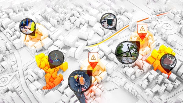
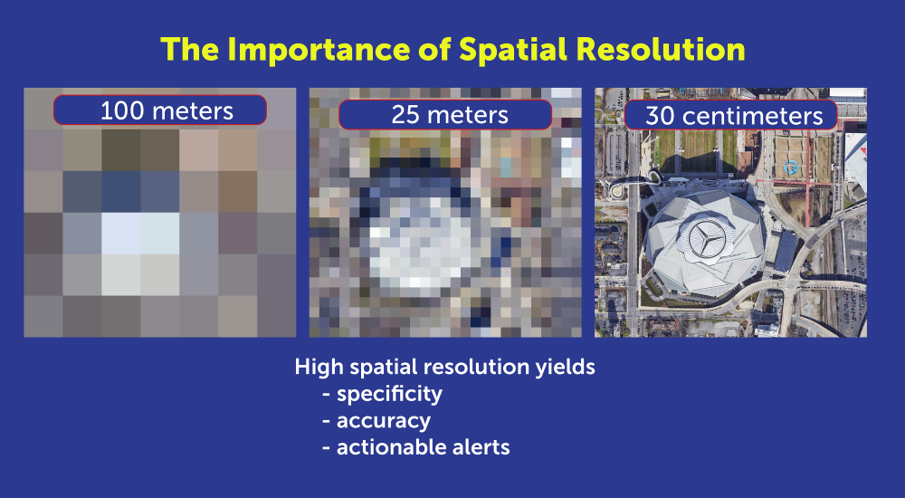
    Advances in remote sensing, AI, and GIS now enable utilities to monitor rights-of-way from 270 miles up. Using satellite imaging and AI algorithms, utilities can continuously monitor pipeline and cable corridors and help close the visibility gap. Commercial satellite images from providers such as Airbus and Vantor (formerly known as Maxar) can provide high-resolution imagery for cloud-based AI processing that can detect changes as small as 30 centimeters, about the size of a dinner plate. Using satellite imaging is also faster and more cost-effective than using drones or aircraft, because cloud computing resources can analyze images in hours, rather than days or weeks.

    High-resolution imagery is necessary for specific, accurate alerts. (Photo: Satelytics)
    High-resolution imagery is necessary for specific, accurate alerts. (Photo: Satelytics)

    To power geospatial analytics, remote sensing technology (RST) captures multispectral and hyperspectral data from high-resolution satellite sensors, then uses AI-powered algorithms to analyze spectral signatures. Spectral imaging can detect a wide range of surface activity, including soil disturbances, vegetation changes, soil grading and trenching, new construction starts, heavy equipment use, new access roads, and encroachment on utility easements; activities that could indicate a risk to buried cables and pipelines.

    Integrating Geospatial AI with ArcGIS

    To make potential problems easier to identify, high-resolution images and geospatial analyses can be fused with GIS asset layers and corridor models to pinpoint anomalies that could indicate excavations or construction that interfere with utility rights-of-way.

    Utilities that already use ArcGIS as their system of record can readily integrate results from geospatial analytics into existing workflows. For example, users can visualize and detect disturbed layers using ArcGIS Pro, tracking surface risk trends and KPIs with ArcGIS dashboards.

    Monitoring the utility corridor for unwanted structures. (Image: Satelytics)
    Monitoring the utility corridor for unwanted structures. (Image: Satelytics)

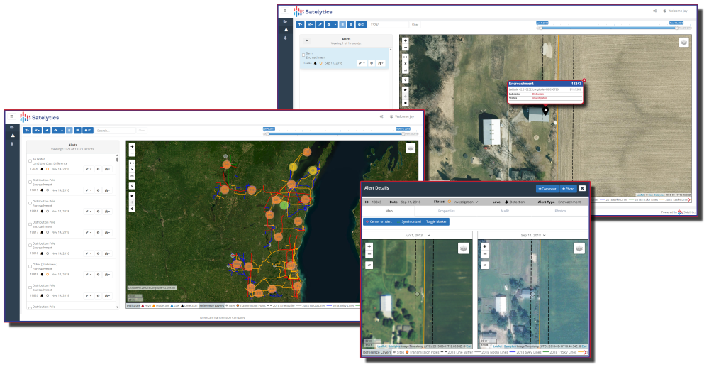
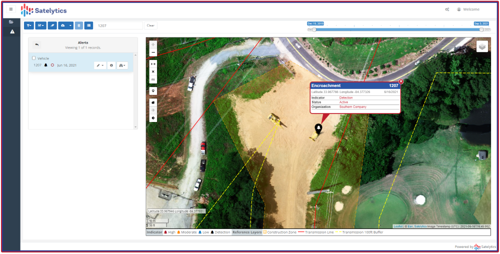
    To show how this works, Southern Company, which owns Georgia Power, Alabama Power and Mississippi Power, needed to identify new construction along its service corridors to detect potential encroachments before construction. Southern Company established a quarterly monitoring schedule with Satelytics, a provider of cloud-based geospatial analytics software.

    Using data from the Pleiades 1A and 1B satellites, Satelytics captured multispectral imagery at 50-centimeter resolution, then used AI-poweredanalytics to detect changes, such as new barns, parking lots, or other construction. Encroachment alerts were delivered through the Satelytics web portal, and the geospatial data was transferred directly to Southern Company’s ArcGIS system via application programming interfaces (APIs).

    Southern Company then compared items flagged in the satellite images with field visits to fine-tune the AI models. Following the pilot program, the AI models were refined to flag only those encroachments that posed a danger or a problem.

    Flagging encroachment risks from space. (Image:: Satelytics)
    Flagging encroachment risks from space. (Image:: Satelytics)

    AI-powered geospatial analytics strengthens Enhanced Positive Response (EPR) by documenting risk locations, including map layers and images, and providing evidence of corridor conflicts and surface changes. While AI accelerates detection, ground truthing remains essential. As shown in our Southern Company example, on-site validation is required to improve machine learning algorithms to increase accuracy. Integrating Field Maps and Survey 123 into AI workflows can verify findings and prioritize responses.

    Using AI and GIS for Predictive Dig Safety

    Geospatial AI technology is becoming an essential tool for more than just excavation monitoring. Using AI to analyze satellite images offers other benefits, such as measuring gas leaks or tracking water and oil leaks. Combining AI, GIS, and historical data will soon be used for predictive excavation risk management, identifying high-risk areas in advance of filing an excavation permit.

    Predictive analytics will continue to play a larger role in excavation monitoring. AI analytics will provide construction forecasts and enable permit intelligence layers in GIS. The same data can power dynamic risk scoring dashboards and support three-dimensional corridor safety twins.

    As new building construction continues to boom, utilities are harnessing the latest technology to prevent excavation incidents and protect underground assets. Combining satellite imagery, AI, and GIS provides the advanced tools needed to maintain continuous asset awareness, closing the visibility gap for underground cables and pipelines. Pipeline operators, electric utilities, and LDCs are reducing operating costs and minimizing environmental impact by leveraging geospatial analytics powered by artificial intelligence.

    Sean Donegan is CEO of Satelytics, a company that uses cloud-based, geospatial analytics to analyze multispectral and hyperspectral imagery to identify pipeline leaks and other environmental issues. Donegan has over 30 years of experience building technology and software companies.

  • Opinion: The U.S. needs GPS backup and IoT resilience

    Opinion: The U.S. needs GPS backup and IoT resilience

    America’s dependence on GPS is a matter of national security, economic vitality, and daily life. We all agree: the United States must develop strong, resilient alternatives to satellite-based positioning, navigation and timing (PNT). The question, ironically enough, is how to get where we want to go.

    Z-Wave Alliance, whose members build the smart home, security, and automation devices used in millions of homes and buildings, fully supports the federal effort to harden PNT infrastructure. We have been active contributors to the FCC’s Notice of Inquiry (WT 25-110) and the Department of Transportation’s Complementary PNT (CPNT) research program. We have provided and assessed technical data to help identify which terrestrial and space-based solutions can truly coexist with the technologies Americans already use every day.

    A Known Risk

    NextNav has petitioned the FCC to restructure parts of the lower 900 MHzband to host a terrestrial 5G/PNT network—essentially a ground-based GPS complement. The company’s plan would allocate parts of that band for high-power transmissions and relax the long-standing protections that keep low-power (Part 15) devices from destructive interference.

    That same spectrum underpins hundreds of millions of existing systems: connected security sensors, toll-booth readers, smart meters, building automation networks, and the smart home products consumers rely on every day. These devices operate safely and efficiently because the FCC’s Part 15 rules limit interference and prohibit high-power operations in this shared public band.

    Robust technical analysis, most recently the Pericle Communications study commissioned by the Security Industry Association, shows that high-power terrestrial PNT transmissions would block or degrade low-power communications up to 60 percent of the time. In plain terms, that means alarms that fail to trigger, silent sensors, and lost connectivity for devices that safeguard homes, businesses, and infrastructure.

    Evidence indicates these devices could degrade significantly in performance, often to the point of un-usability. Once the band is reclassified, there’s no practical way to “retrofit” the millions of products already deployed. The result would be billions of dollars in stranded hardware, irrecoverable damage to company reputations, and a long, expensive replacement cycle for utilities, business owners, and consumers.

    This isn’t an argument against terrestrial PNT. It’s an argument for evidence-based engineering.

    — Avi Rosenthal

    Multiple Paths to Resilient PNT

    This isn’t an argument against terrestrial PNT. It’s an argument for evidence-based engineering. The Department of Transportation has identified several categories of GPS-complement technologies, including low-Earth orbit (LEO) satellite systems, time-over-fiber distribution, map matching/map tracking, and terrestrial RF. NextNav’s 900 MHz concept falls into the fourth category, but it’s only one of many.

    The FCC recognized this when it opened its broad Notice of Inquiry in March 2025 instead of rushing into rulemaking. Other federally funded trials, such as the Broadcast Positioning System developed by NAB and UrsaNav’s eLoran solution, show that terrestrial PNT can be achieved without displacing unlicensed Part 15 devices.

    Engineering redundancy into national infrastructure demands that we test multiple solutions in parallel, not gamble on a single proprietary approach that risks breaking what already works.

    Coexistence Is the Standard, Not the Exception

    Across every modern wireless domain — Wi-Fi, Bluetooth, Zigbee, Z-Wave, LoRa, Wi-SUN — coexistence testing is standard practice. Before a new technology enters a shared spectrum, it must demonstrate that it can live alongside incumbents. NextNav has not done that. Its coexistence claims rely primarily on simulations using optimistic assumptions about device density and duty cycle. Real-world deployments are far denser and far noisier.

    Z-Wave and our industry partners simply ask for what every responsible engineer would: comprehensive, transparent field testing before the FCC alters the rules of a crowded band. That’s not obstructionism: it’s diligence.

    Building Forward, Not Backward

    Our message is simple: the U.S. needs PNT redundancy, but it must be built on coexistence, not displacement.

    America’s connected infrastructure relies on the lower 900 MHz band precisely because it has been open, unlicensed, and reliable. Allowing a single licensee to flood that band with high-power signals would trade resilience for fragility.

    Z-Wave Alliance stands ready to collaborate with the FCC, DOT, and all research participants to ensure the U.S. gets the GPS backup it deserves: one that strengthens, rather than undermines, the technologies that keep Americans safe, secure, and connected every day. To learn more, follow Z-Wave Alliance on LinkedIn and across social platforms: we are committed to keeping the U.S. technology community up-to-date on key proposal developments and opportunities to make their voices heard.

  • The U.S. needs GPS backup and IoT resilience

    The U.S. needs GPS backup and IoT resilience

    America’s dependence on GPS is a matter of national security, economic vitality, and daily life. We all agree: the United States must develop strong, resilient alternatives to satellite-based positioning, navigation and timing (PNT). The question, ironically enough, is how to get where we want to go.

    Z-Wave Alliance, whose members build the smart home, security, and automation devices used in millions of homes and buildings, fully supports the federal effort to harden PNT infrastructure. We have been active contributors to the FCC’s Notice of Inquiry (WT 25-110) and the Department of Transportation’s Complementary PNT (CPNT) research program. We have provided and assessed technical data to help identify which terrestrial and space-based solutions can truly coexist with the technologies Americans already use every day.

    A Known Risk

    NextNav has petitioned the FCC to restructure parts of the lower 900 MHzband to host a terrestrial 5G/PNT network—essentially a ground-based GPS complement. The company’s plan would allocate parts of that band for high-power transmissions and relax the long-standing protections that keep low-power (Part 15) devices from destructive interference.

    That same spectrum underpins hundreds of millions of existing systems: connected security sensors, toll-booth readers, smart meters, building automation networks, and the smart home products consumers rely on every day. These devices operate safely and efficiently because the FCC’s Part 15 rules limit interference and prohibit high-power operations in this shared public band.

    Robust technical analysis, most recently the Pericle Communications study commissioned by the Security Industry Association, shows that high-power terrestrial PNT transmissions would block or degrade low-power communications up to 60 percent of the time. In plain terms, that means alarms that fail to trigger, silent sensors, and lost connectivity for devices that safeguard homes, businesses, and infrastructure.

    Evidence indicates these devices could degrade significantly in performance, often to the point of un-usability. Once the band is reclassified, there’s no practical way to “retrofit” the millions of products already deployed. The result would be billions of dollars in stranded hardware, irrecoverable damage to company reputations, and a long, expensive replacement cycle for utilities, business owners, and consumers.

    This isn’t an argument against terrestrial PNT. It’s an argument for evidence-based engineering.

    — Avi Rosenthal

    Multiple Paths to Resilient PNT

    This isn’t an argument against terrestrial PNT. It’s an argument for evidence-based engineering. The Department of Transportation has identified several categories of GPS-complement technologies, including low-Earth orbit (LEO) satellite systems, time-over-fiber distribution, map matching/map tracking, and terrestrial RF. NextNav’s 900 MHz concept falls into the fourth category, but it’s only one of many.

    The FCC recognized this when it opened its broad Notice of Inquiry in March 2025 instead of rushing into rulemaking. Other federally funded trials, such as the Broadcast Positioning System developed by NAB and UrsaNav’s eLoran solution, show that terrestrial PNT can be achieved without displacing unlicensed Part 15 devices.

    Engineering redundancy into national infrastructure demands that we test multiple solutions in parallel, not gamble on a single proprietary approach that risks breaking what already works.

    Coexistence Is the Standard, Not the Exception

    Across every modern wireless domain — Wi-Fi, Bluetooth, Zigbee, Z-Wave, LoRa, Wi-SUN — coexistence testing is standard practice. Before a new technology enters a shared spectrum, it must demonstrate that it can live alongside incumbents. NextNav has not done that. Its coexistence claims rely primarily on simulations using optimistic assumptions about device density and duty cycle. Real-world deployments are far denser and far noisier.

    Z-Wave and our industry partners simply ask for what every responsible engineer would: comprehensive, transparent field testing before the FCC alters the rules of a crowded band. That’s not obstructionism: it’s diligence.

    Building Forward, Not Backward

    Our message is simple: the U.S. needs PNT redundancy, but it must be built on coexistence, not displacement.

    America’s connected infrastructure relies on the lower 900 MHz band precisely because it has been open, unlicensed, and reliable. Allowing a single licensee to flood that band with high-power signals would trade resilience for fragility.

    Z-Wave Alliance stands ready to collaborate with the FCC, DOT, and all research participants to ensure the U.S. gets the GPS backup it deserves: one that strengthens, rather than undermines, the technologies that keep Americans safe, secure, and connected every day. To learn more, follow Z-Wave Alliance on LinkedIn and across social platforms: we are committed to keeping the U.S. technology community up-to-date on key proposal developments and opportunities to make their voices heard.

  • Advancing vehicle autonomy with reliable GNSS

    Advancing vehicle autonomy with reliable GNSS

    GNSS technology has had a reputation for unreliability in safety-critical applications, such as advanced driver assistance systems (ADAS). This perception has shaped automotive design and manufacturing: some ADAS developers have avoided GNSS altogether, instead relying on cameras, lidar and other sensors. Here, Manuel Del Castillo, VP of business development at Focal Point Positioning, explains how, with the right reliability, GNSS can offer a powerful layer of redundancy and support these other sensor types.


    The hesitation to include GNSS in ADAS stacks is historical. Traditionally, this technology was unreliable, especially in dense, urban environments where satellite signals were obstructed. Consequently, many automakers turned to alternative sensors. For example, cameras can identify lane markings, traffic signs and objects, while lidar can build highly detailed 3D maps of the vehicle’s surroundings.

    Each of these sensors provides important navigational data. However, they all describe a car’s location relative to its immediate environment. With no reliable source of absolute positioning, these relative measurements can’t confirm the vehicle’s exact place in the world — information that is critical for safe navigation.    

    Why ADAS Needs GNSS

    Cameras, lidar and other sensors provide rich environmental data. However, they are limited by what they can directly observe. A camera can identify lane markings but can’t confirm which road the vehicle is on when multiple lanes or junctions overlap. Similarly, lidar can map obstacles in 3D, but without a wider frame of reference, it will struggle to anchor that map to the road network. HD maps provide another valuable layer, but without an accurate global position, they too can be misaligned with the real world, limiting their value.

    GNSS can help plug this gap. By supplying absolute latitude and longitude, it ensures that the relative information from the other sensors is grounded in the correct location. GNSS helps calibrate and initialise other sensors, while also providing a cross-check against their measurements to detect potential errors or drift in sensor performance over time. Therefore, reliable GNSS is not an alternative to cameras, lidar or radar. It complements these sensors and boosts accuracy and the reliability of the overall system.

    The Importance of Redundancy

    Increasingly, the importance of GNSS in ADAS stacks is being recognised. As automotive production moves toward L3 automation and beyond, the demand for absolute positioning increases, along with the need for safe, layered sensing. GNSS, alongside cameras, lidar and radar, can help automakers improve navigational resilience without reinventing vehicular architectures.

    Reliable GNSS isn’t about replacing other technologies. It is about reinforcing them. Having a global frame of reference helps ensure that the relative data from other sensors is grounded in the correct place. For automakers, the next step is recognising that GNSS can improve safety and trust in ADAS stacks, supporting the transition toward autonomous driving.

    Advancing GNSS Reliability

    Even with GNSS integrated into the vehicle’s sensors, challenges remain. Urban canyons and dense foliage can  attenuate or even block satellite signals and create reflections, reducing accuracy. Since ADAS systems need reliably accurate absolute positioning, these challenges need to be addressed if we want  GNSS to play a role in ADAS.

    Newer, more sophisticated GNSS solutions are needed. The progression to Level 3 does not require an entirely new technology stack but rather extracting the very best from each of the existing components. For GNSS, this evolution involves implementing software-based solutions to achieve the necessary reliability improvements without overhauling hardware components. Pursuing cost-effective upgrades enhances performance without necessitating complete system redesigns, thereby keeping costs under control.

    FocalPoint’s S-GNSS Auto software enhances GNSS accuracy in autonomous vehicles, providing reliable, absolute location to improve overall ADAS safety and efficiency. By boosting line-of-sight signals and rejecting non-line-of-sight signals, this simple firmware upgrade can help vehicles maintain accuracy in challenging environments.

    By reducing positional uncertainty, these enhanced GNSS solutions strengthen the overall sensor stack. Together, these layers improve resilience, safety, and confidence in higher levels of vehicle automation.

    As the automotive industry moves further towards L3 automation and beyond, reliable data on absolute position will be essential and will only reinforce the insights captured by cameras, lidar and other sensors.

    To find out how S-GNSS Auto can help automotive OEMs transition to L3 autonomy, download FocalPoint’s white paper here.

  • Scripps Institution of Oceanography expands geodetic program

    Scripps Institution of Oceanography expands geodetic program

    My September GPS World newsletter highlighted the new California Spatial Reference Network, labeled CSRN Epoch 2025.00. These coordinate changes will impact geospatial users across California, and understanding the transition process is important for preparing for the modernized National Spatial Reference System (NSRS), expected to be adopted in 2026.

    This newsletter will focus on the California Spatial Reference Center (CSRC) and the Geodetic Program at Scripps Institution of Oceanography (SIO).

    CSRC, founded in 1997 and formally dedicated in 2001, develops and maintains a modern network of GPS control stations to provide a reliable spatial reference system for California. Created as a partnership of surveyors, engineers, GIS professionals, the National Geodetic Survey (NGS), Caltrans, and the geodetic and geophysical communities, the CSRC’s mission is to produce a self-sustaining, up-to-date geodetic control network for the state.

    The CSRC holds Coordinating Council meetings to review CSRC activities and related state surveying and mapping efforts. The box titled “CSRC Coordinating Council 2025 Fall Meeting” lists the agenda for the most recent meeting. I attend these meetings virtually; they are consistently informative and I enjoy participating.

    Image: CSRS website
    Image: CSRS website

    Dr. Yehuda Bock’s Director’s Report (SOPAC/CSRC Director, Dept. IGPP, Scripps Oceanography, UCSD) is available for download from the CSRC website: http://sopac-csrc.ucsd.edu/index.php/csrc-presentations/ (note: large file). At the Fall Coordinating Council Meeting Yehuda opened with a presentation on the new California Spatial Reference Network, CSRN Epoch 2025.00. I encourage readers to download the presentation or read my September GPS World newsletter, which highlighted CSRN Epoch 2025.00. This newsletter will focus on the Geodetic Program at Scripps Institution of Oceanography (SIO).

    Image: CSRC website
    Image: CSRC website

    In my November 2023 GPS World newsletter, I noted NGS’s announcement of the NOAA FY23 Geospatial Modeling Competition awardees. In my March 2024 GPS World newsletter, I  highlighted Scripps Institution of Oceanography’s (SIO) proposal. As noted there, Yehuda’s proposal included three activities:

    • Create a formal Geodesy Program at SIO to address the nationwide deficiency of geodesists. Expand current geophysics curriculum – funding for five graduate students.
    • Develop an IFDM to supplement the NSRS for users in regions with significant ground motions, using GNSS and InSAR/GNSS displacement fields (funded by NASA projects) and underlying geophysical models. CSRC will exercise the IFDM through its community of public, private and academic users of precise spatial referencing in our challenging region of secular and transient crustal movements.
    • Investigate a unified vertical reference frame, including a marine geoid optimized to be consistent with the full spectrum of observations from modern gravimetric geoids (e.g., GRAV-D, ICGEM), remotely sensed observations (e.g., SWOT, ICESat-2), in situ ocean observations and assimilating ocean models and the TRF.

    At the Fall Coordinating Council Meeting, Yehuda provided an update on the status of the Geodesy Program at SIO.  It was mentioned that some of the students are funded by the National Geodetic Survey (NGS)’s grant but others are funded by the National Geospatial-Intelligence Agency (NGA), United States Geological Survey (USGS), and the Office of Naval Research (ONR).

    Image: CSRC website
    Image: CSRC website
    Image: CSRC website
    Geodesy track curriculum. (Image: CSRC website)
    Geodesy track curriculum. (Image: CSRC website)

    As mentioned in the Director’s report, they have initiated bi-weekly geodesy track seminars to discuss research projects related to NGS and other grants.  Four videos by students discussing their projects were shown during Yehuda’s presentation. 

    The following are the titles and presenters of the four research projects:

    • San Jacinto Fault Zone by Neil Waldhausen
    • Probing Antarctic basal ice state using airborne geodesy by Briar Conger
    • Repeat Pass Interferometry by Rubi Garcia Gonzalez
    • Hydrologic monitoring with GRACE/GRACE-FO by Logan Platt

    San Jacinto Fault Zone by Neil Waldhausen

    I have included a few bullets summarizing their project and a few captured images from the videos.  I would encourage everyone to download the presentation to listen to the short videos by these students. The presentations are only 90 seconds but are very interesting. Readers can contact the speakers through the University to find out more about their research.

    Summary of the “San Jacinto Fault Zone” video:

    • Neil uses GNSS to measure velocities and strain rates around the San Jacinto Fault.
    • He focused on the Anza gap, a 20-km segment of the fault.
    • He re-surveyed about 50 monuments that had been occupied over past decades.
    • His work has lowered uncertainties in many site velocity measurements.
    • His aim is to further reduce uncertainties in strain-rate and slip-rate estimates to better understand the Anza gap’s mechanics.
    San Jacinto Fault Zone by Neil Waldhausen.
    San Jacinto Fault Zone by Neil Waldhausen.
    San Jacinto Fault Zone by Neil Waldhausen.
    San Jacinto Fault Zone by Neil Waldhausen.
    Image: CSRC Website
    Image: CSRC website

    Summary of the “Probing Antarctic Basal Ice State Using Airborne Geodesy” video:

    • Briar’s project uses gravity and radar data to study basal hydrology — water flow beneath glaciers and ice sheets, including subglacial lakes, channels, and pressure-driven water movement.
    • He conducted fieldwork on the East Antarctic Ice Sheet during the 2023–24 season.
    • He collected airborne gravity and GNSS data from a converted DC-3 aircraft.
    • Data processing uses both PPP and differential positioning methods.
    • His aim is to improve long-term sea-level rise predictions.
    • He is also developing a fixed-wing UAV capable of collecting lidar, gravity, and photogrammetry data.

    Probing Antarctic Basal Ice State Using Airborne Geodesy by Briar Conger

    Probing Antarctic Basal Ice State Using Airborne Geodesy by Briar Conger.
    Probing Antarctic Basal Ice State Using Airborne Geodesy by Briar Conger.
    Image: CSRC website
    Image: CSRC website

    Summary of the “Repeat Pass Interferometry” video:

    • Rubi used repeat-pass interferometry (phase gradient) to map small-scale surface deformation.
    • The phase gradient is the change in interferometric phase between neighboring pixels; unlike the ambiguous single-pixel phase (wrapped within 2π), the gradient gives a continuous local rate of change useful for analysis.
    • She compared fractures identified by phase-gradient analyses with historic fracture databases.
    • Her ongoing work includes applying Andersonian faulting theory to assess whether fractures formed before or after earthquakes.
      • Andersonian faulting (Anderson’s theory of faulting) is a geological framework for interpreting crustal stress and fault geometry; it’s used to interpret InSAR-measured deformation. While not a method of analysis for InSAR data itself, it serves as a critical interpretive tool for understanding the ground deformation patterns measured by InSAR.

    Repeat Pass Interferometry by Rubi Garcia Gonzalez

    Repeat Pass Interferometry by Rubi Garcia Gonzalez.
    Repeat Pass Interferometry by Rubi Garcia Gonzalez.
    Image: CSRC website
    Image: CSRC website

    Summary of the “Hydrologic monitoring with GRACE/GRACE-FO” video:

    • Logan described using satellite measurements of tiny changes in Earth’s gravity to track mass movement and better understand groundwater and the water cycle.
    • He relied on GRACE and GRACE-FO data.
      • The Gravity Recovery and Climate Experiment (GRACE) and its successor mission, GRACE-Follow On (GRACE-FO), are Earth-observation missions that use twin satellites to precisely map changes in Earth’s gravity field over time. This unique method allows scientists to track the movement of mass, primarily water, around the planet
    • He used the GRACE data to look at changes in California’s Water storage from 2004 to 2024.
      • Results indicate a decline due to drought and heavy ground water usage, with more water being stored in northern California than southern California.
    • This research supports water management, climate-change impact assessment, and strategies for sustainable groundwater use.

    Hydrologic Monitoring with GRACE/GRACE-FO by Logan Platt

    Hydrologic Monitoring with GRACE/GRACE-FO by Logan Platt.
    Hydrologic Monitoring with GRACE/GRACE-FO by Logan Platt.
    Hydrologic Monitoring with GRACE/GRACE-FO by Logan Platt.
    Hydrologic Monitoring with GRACE/GRACE-FO by Logan Platt.
    Image: CSRC Website
    Image: CSRC website

    A new InSAR textbook, authored by several internationally recognized researchers, was also announced. Funded by the National Geodetic Survey and published Open Access, the book is available for free download. It’s a large file, but anyone working with InSAR data should obtain a copy.

    New InSAR Textbook

    Image: CSRC website
    Image: CSRC website

    Table of Contents of New InSAR Textbook

    If you’ve read my newsletters, you know I’m passionate about advancing geodesy. I wanted to share one of Yehuda’s slides, “What Geodesy Can Tell Us About Earth,” because the four students are working on projects tied to real-world problems. The slide highlights geodesy’s importance and the many professions that rely on its findings.

    What geodesy can tell us about Earth. (Image: CSRC website)
    What geodesy can tell us about Earth. (Image: CSRC website)
  • Building the future of localization: how GNSS+IMU and VPS work together

    Building the future of localization: how GNSS+IMU and VPS work together

    Accurate localization underpins modern mobility, powering everything from precise rideshare pickups and efficient deliveries to augmented reality and autonomous systems. Yet achieving reliable sub-meter precision with commodity hardware remains one of the field’s central challenges.

    A range of technologies are being explored to improve positioning, such as real-time kinematic (RTK) and Precise Point Positioning (PPP) corrections, 5G methods standardized under the 3rd Generation Partnership Project (3GPP), simultaneous localization and mapping (SLAM), light detection and ranging (lidar), inertial measurement units (IMUs), and ultra-wideband (UWB). Each plays a role in specific contexts, but for everyday, mass-market deployment, two paradigms dominate the conversation: visual positioning systems (VPS), which rely on cameras and computer vision to match images against reference databases, and GNSS plus inertial measurement unit (GNSS+IMU) sensor fusion, which integrates satellite positioning with inertial data already present in billions of devices.

    These two approaches are not mutually exclusive. VPS works best in dense urban areas where GNSS can struggle, while GNSS+IMU excels in the open environments where VPS has fewer features to recognize. In practice, VPS even depends on GNSS to help narrow the search space in its visual database. That makes the two technologies natural complements, and together they provide the building blocks for the next generation of spatial intelligence.

    The Role of VPS

    VPS use computer vision to determine position relative to known landmarks. In favorable environments – especially dense, feature-rich urban settings — they can deliver impressive accuracy. VPS has been successfully applied in AR anchoring, pedestrian navigation, and even some indoor mapping, offering a level of precision that is difficult to match with GNSS alone.

    At the same time, VPS faces challenges that limit its ability to scale as a standalone universal solution. Maintaining vast libraries of reference imagery requires constant collection and refreshing, even for companies with resources such as Google’s Street View. Keeping cameras active and running neural network matching consumes power and compute, with AR and navigation apps often showing rapid battery drain when vision pipelines are engaged.

    Performance can also be fragile, with accuracy dropping in low light, bad weather, or environments with limited features such as open fields or glass-heavy corridors where reflections distort recognition. Because VPS requires continuous camera use, it also raises privacy concerns under regulations like GDPR.

    But VPS still fills an important feature set: it works best in exactly the environments where GNSS struggles most. In dense urban areas with abundant visual features but heavy multi-path interference, VPS provides a complementary capability that enhances overall localization performance when paired with GNSS+IMU.

    GNSS+IMU Fusion

    GNSS provides global reach, but smartphone accuracy typically ranges from 3m to 5 m. This may be adequate for turn-by-turn navigation, but it does not meet the precision required for lane-level guidance, pedestrian navigation or building entrances. Pairing GNSS with IMU data changes that equation by adding orientation and motion context.

    Sensor fusion combines GNSS position (x, y, z) with IMU-derived orientation (α, β, γ) to deliver six degrees of freedom (6DoF). In practice, this allows devices to determine not only where they are, but also which way they are facing, which is critical for navigation and AR anchoring.

    Another key advantage is that fusion also runs efficiently on-device, using low-power sensors already embedded in nearly every phone. It avoids the battery drain and compute overhead of vision-based methods, remains resilient in poor visibility, and largely sidesteps the privacy concerns associated with continuous camera use.

    Together, GNSS+IMU and VPS offer complementary strengths: GNSS+IMU provides scalable global coverage, while VPS adds value in dense urban or visually rich environments. Used in tandem, they extend reliable sub-meter localization across a far wider range of real-world scenarios.

    Performance in Field Tests

    Independent field testing has underscored the impact of GNSS+IMU fusion in real-world conditions. In trials conducted in Louisville, Colorado, standard smartphones relying solely on GNSS averaged ~1.9 meters of error. When collaborative corrections and IMU fusion were added, mean error dropped to ~0.55 meters – a more than threefold improvement.

    To benchmark localization performance against visual methods, we compared heading determination from Zephr’s sensor-based approach with Google’s VPS, widely considered an industry leader in vision-based localization. Using the same device and location, headings generated from ArPose and Zephr were plotted against VPS outputs.

    Figure 1: The figure shows a strong correlation, with a mean heading difference of just 7.58• and a heading correlation of 99.52%.
    Figure 1: The figure shows a strong correlation, with a mean heading difference of just 7.58° and a heading correlation of 99.52%.

    The results in Figure 1 show a strong correlation, with a mean heading difference of just 7.58 degrees and a heading correlation of 99.52%. This provides a useful benchmark, illustrating that sensor-based approaches can achieve heading accuracy on par with vision-based systems while avoiding the data, compute, and privacy burdens tied to continuous camera use.

    Head-to-Head Comparison

    When considered side by side, VPS and GNSS+IMU reveal distinct strengths. VPS delivers high accuracy in dense urban environments, where GNSS can be degraded by multipath or blockage. GNSS+IMU, meanwhile, provides consistent global coverage and efficient performance in open environments where VPS has fewer features to recognize. Taken together, they form a complementary toolset, with each addressing the other’s gaps.

    • Cost & Infrastructure: VPS offers detailed visual positioning but requires continuous investment in capturing and updating reference imagery, which can run into petabytes of data and demand large-scale cloud storage. GNSS+IMU leverages existing satellite constellations and commodity sensors already embedded in smartphones, scaling naturally without additional infrastructure.
    • Battery & Compute: VPS enables precise landmark recognition but must keep cameras active and process high-resolution frames, a pipeline that consumes energy and compute. GNSS+IMU fuses lightweight sensor readings on-device, sustaining real-time performance with minimal power. Hybrid systems can use VPS selectively for visual anchors when power budgets allow.
    • Environmental Robustness: VPS excels in dense urban cores where landmarks are abundant, but its performance can degrade in low light, heavy weather, or feature-poor settings such as highways or open fields. GNSS+IMU continues to perform in most outdoor environments, with IMUs bridging short GNSS gaps in tunnels or urban canyons. Together, they extend reliable coverage across diverse conditions.
    • Privacy: VPS provides visual context but depends on continuous camera feeds, which can raise concerns under regulations like GDPR and CCPA. GNSS+IMU relies solely on inertial and satellite data, which can be anonymized and processed on-device. Privacy-conscious applications may favor GNSS+IMU as the default, while invoking VPS in controlled contexts.
    • Scalability: VPS delivers strong results in mapped geographies but is constrained by the cost of collecting and maintaining visual data globally. GNSS+IMU scales as more devices ship with standard GNSS receivers and inertial sensors, with accuracy improving further when devices contribute corrections to a shared network. In combination, VPS can add value in high-density urban corridors where visual richness offsets its infrastructure demands.

    Beyond Accuracy: Spatial Intelligence Without Cameras

    GNSS+IMU fusion not only narrows positioning error but also provides contextual awareness. By combining positional vectors with device orientation, systems can determine not just where a device is, but what lies within its field of view.

    This contextual layer enables landmark-aware navigation and natural AI interactions. Instead of vague coordinates, users could be guided to “meet at the blue mailbox next to the coffee shop entrance.” In AR, digital content can be anchored to the physical world without the overhead of vision-based methods. And for AI interfaces, assistants could answer spatial queries (“Is the restaurant to my right or left?”) with precision that feels intuitive.

    While GNSS+IMU avoids reliance on cameras, VPS can still add complementary value by providing visual anchors in feature-rich spaces. Used together, the two methods create a more resilient and adaptive localization system, able to support a wider range of real-world scenarios than either could alone.

    A Clearer Path Forward

    VPS has proven valuable in research, robotics, and AR demonstrations, particularly in dense urban environments. But its reliance on imagery, heavy compute, and continuous camera use makes it difficult to scale as a universal solution for sub-meter accuracy.

    To unlock the next generation of spatially intelligent applications, from context-aware assistants to immersive AR, localization must be both practical and massively scalable. This foundation will come from GNSS+IMU sensor fusion, complemented by vision-based methods where they add value. GNSS+IMU builds on infrastructure and sensors already present in billions of devices, delivers efficient on-device performance, and avoids the privacy tradeoffs of camera-based systems.

    As positioning becomes the backbone of spatial AI, the evidence points to a decisive outcome: the future will be multimodal, but the scalable backbone will be GNSS+IMU fusion since it empowers devices to understand and interact with the world reliably, with or without cameras.

  • Implementing assured PNT for static and dynamic applications

    Implementing assured PNT for static and dynamic applications

    Position, navigation and timing (PNT) services, derived primarily from GNSS constellations, have become a critical element underpinning the global economy, with a vast range of sectors depending on these signals.

    This includes coordinating financial transactions, stabilizing power grids as well as navigation, with supply chains set to become more reliant on the technology as autonomous vehicles become prevalent. However, GNSS is a vulnerable technology, with faint signals from medium-Earth orbit (MEO) satellites being susceptible to disruption.

    In this article we’ll look at how both static and dynamic applications can achieve resilient PNT, with strategies and sensor fusion techniques that allow operational capability when GNSS is denied.


    Seven hundred. That’s the number of GPS interference events such as jamming and spoofing that take place every single day, according to the U.S. government. And this number is increasing across North America and Western Europe, with it being especially prevalent in or near war zones.

    Indeed, in August, the navigation system of a plane carrying the EU President, Ursula von de Leyen, was reportedly targeted by a GPS jamming attack as it was due to land in Bulgaria — forcing pilots to rely on paper maps. And GPS interference has been linked to the crash of Azerbaijan Airlines flight J2-8243, which was shot down on Christmas Day, 2024.

    Relying on a single source for PNT is no longer a viable strategy and developing a resilient PNT ecosystem that can function in D3SOE (denied, degraded, and disrupted space operational environments) has become essential.

    While navigation is the most commonly understood application of PNT, the timing component is critical in so many of the static systems we rely on — not just finance and power (as listed above) but for AI data centers, asset tracking systems and communication networks — which require precise and stable time references to ensure data integrity, and need these to be synchronized across global networks.

    For such systems, the consequences of getting timing off by even the smallest amount can be seen in the 2016 decommissioning of the SVN23 GPS satellite. During this, a software error created a 13.7 microsecond anomaly across the entire constellation that, according to a UK government report caused issues with digital radio broadcasts and communication networks. The event is also seen by some as a warning for the financial sector and in particular for high-frequency trading (HFT), where trades take place in millionths and studies have suggested that a 1 ms advantage in trading applications could be worth $100 million a year to a major brokerage firm.

    By subtly altering timing signals used by trading systems, malicious actors can effectively see and use market data “from the future” and enact transfers worth billions of dollars.

    Similarly, a timing attack on the phasor measurement units (PMUs) used to measure real-time stress in power grids could trigger major blackouts. The effect of such an attack can be seen in 2003’s (pre-PMU) Northeast Blackout, in which a sagging power line touched tree and caused a series of cascading outages that affected 55 million people across the U.S. and Canada. 

    And further putting the importance of protecting PNT in context, in 2020 the U.S. defined 16 critical infrastructure sectors as part of its Executive Order 13905. Of these 14 (88%) of these are reliant on PNT for their safe operation. Going beyond the energy and finance examples above, this includes sectors like communications, transportation, and agriculture. In short, PNT resilience is essential across virtually the entire economy.

    Detecting a Compromised GNSS Signal

    Of course, the first stage in protecting a PNT signal is in the identification of an attack, and several techniques can be used to identify inconsistencies that point to jamming or spoofing.

    These range from the analysis of the signal’s Doppler shift (transmissions from nearby terrestrial spoofer will have a near-zero Doppler shift) to techniques like RAIM (receiver autonomous integrity monitoring), which continually recalculates position while excluding one satellite each time to see if the results are consistent.

    Cryptographic methods, such as Galileo’s Open Service Navigation Message Authentication (OSNMA), are also available to verify a satellite’s digital signature and confirm the data’s authenticity.

    However, relying on cryptographic authentication alone still comes with risks. Notably, authenticated signals are susceptible to meaconing attacks, where a legitimate signal is recorded and replayed later to mislead a receiver. It is, however, possible to counter these attacks using a secure, out-of-band verification layer for all GNSS constellations. This involves the independent delivery of authentication data with hash authentication transmitted via encrypted L-band correction signals from geostationary (GEO) satellites.

    This approach can also be retrofitted to older equipment using PNT by using an RSR transcoding device (see below).

    For dynamic systems, an additional level of validation can be gained by inertial sensors, comparing their output against PNT data to detect both sudden large jumps in position and continual slight deviations that can be characteristic of a sophisticated spoofing attack.

    Timing in Static Applications

    The timing architecture of such systems must go beyond simply identifying a threat and validate incoming data. This requires the integration of alternative PNT sources through an intelligent sensor fusion framework. To achieve this level of resilience in a fixed location, a multi-source, zero-trust approach is necessary. This involves augmenting or replacing GNSS with a layered defense of terrestrial and alternative space-based signals that can be authenticated and trusted.

    Modern PTP grandmasters utilize the latest sub-microsecond accuracy Precision Time Protocol (PTP) and the more common millisecond-range Network Time Protocol (NTP) to ensure compatibility with nearly all standard IT equipment.

    High-speed 25G PTP Ethernet connections are also being implemented to support high-performance AI data centers and financial exchanges without creating data bottlenecks. To ensure continuous operation during extended GNSS outages, these systems can draw synchronization from terrestrial sources like a network PTP feed or an optional atomic caesium clock.

    Furthermore, it is also possible to use encrypted L-Band signals from geostationary (GEO) satellites, such as those from Inmarsat, which create an enhanced timing service with built-in GNSS authentication and anti-spoofing features to deliver timing accuracy of sub-5 ns.

    Figure 1: VIAVI’s Inertial Labs division has developed a Visual-Inertial Navigation System (VINS) that combines 3D vision aided mapping with inertial accelerometers to enable positioning in D3SOE environments – shown in prototyping stage
    Figure 1: VIAVI’s Inertial Labs division has developed a Visual-Inertial Navigation System (VINS) that combines 3D vision aided mapping with inertial accelerometers to enable positioning in D3SOE environments — shown in prototyping stage.

    Navigation Without a North Star

    While static applications can utilize fixed terrestrial infrastructure for backup, dynamic systems do not have this luxury.

    The inherent weakness of RF signals makes them easy to overpower through deliberate jamming by hostile actors. As such, navigation systems onboard UAVs and autonomous vehicles, as well as manned commercial and military vehicles require self-contained navigation capabilities that can function reliably when GNSS signals are compromised. This has driven significant advances in inertial navigation.

    Sensors like accelerometers and gyroscopes have become a critical source for orientation and direction data that remains available at all times. The development of micro-electromechanical systems (MEMS) has been crucial, enabling the integration of inertial navigation into even the smallest systems.

    These sensors aren’t an alternative to PNT satellites. By their very nature they will accumulate errors over time, with sensor bias causing drift and random-walk deviations allowing random noise in each measurement to accumulate. However, recent years have seen significant gains in their accuracy, allowing navigation to continue for short periods after GNSS data is compromised.

    Combining these inertial sensors with sensor fusion techniques also allows each element in a multi sensor system (using magnetometer; and accelerometers/ gyroscopes for roll, pitch and yaw…) to be continually verified by the others for further improvements in accuracy, reducing overall level of error. Data from these IMUs can also be fused with signals from alternative satellite constellations like those in LEO.

    LEO satellite signals are less accurate for timing than GNSS (around 80 ns vs. sub-15 ns) but are significantly stronger. For example, the Iridium LEO STL signal is c.1,000 times stronger than GNSS, making these signals both more resistant to jamming and harder to undertake a (successful) denial of service.

    More recently, techniques using downward-facing camera to track fixed identifiable landmarks have been developed as an alternative / additional data validation method for dynamic systems.

    These external sources provide absolute reference points that can be used to correct the inertial system’s calculations, dramatically improving accuracy and enabling reliable navigation for much longer periods.

    Figure 2: VIAVI’s SecureTime uses GEO and LEO constellations to provide positioning and timing signals that are resilient to attacks.
    Figure 2: VIAVI’s SecureTime uses GEO and LEO constellations to provide positioning and timing signals that are resilient to attacks.

    Sensor Fusion Gives Resilience

    The limitations of individual PNT sources — whether the vulnerability of GNSS or the inherent drift of inertial sensors — mean they cannot depend on a single technology. The most effective strategy is often a hybrid one, combining a high-accuracy inertial sensor unit with inputs from other sensors.

    As we touched on above, adding data sources improves the ability to detect and counter PNT attacks. For example, the EU has confirmed it will deploy additional LEO satellites to bolster its ability to detect GPS interference. And vision cameras can also be used as part of a Visual-Aided Inertial Navigation System (VINS), which provides a powerful method for maintaining an accurate position in the complete absence of GNSS signals.

    This technique was developed in 2025 by VIAVI’s Inertial Labs division, with VINS combining processing with multiple inertial sensors to maintain position. This is reinforced with, and calibrated by a 3D vision-based positioning algorithm that compares visual patterns captured by an onboard camera (either daylight or infrared) with pre-loaded, satellite-imagery-derived 3D maps to track against known landmarks. In a GNSS-denied environment, a VINS system can maintain a horizontal position within 35 m, a vertical position within 5 m, and a desired velocity within 0.9 m/s.

    Conclusion: Bridging the Legacy Gap

    While modern systems can be designed from the ground up with a multi-layered, sensor-fusion PNT architecture, there is still the problem of the huge number of legacy systems that are very much prone to attack.

    These legacy PNT systems are still widely used, including in military conflicts where D3SOE attacks are prevalent. To address this vulnerability, resilient signal retransmission technology has been developed to cost-effectively upgrade these older systems. This approach uses RSR transcoders (constellation simulators) to take a trusted PNT signal, derived from multiple assured inputs, and convert it into the standard GPS format that legacy equipment is designed to receive. This set up – in which the GNSS aerial is replaced with the input from the RSR transcoder – allows the existing systems to operate with state-of-the-art resilience without requiring replacement.

    But, as we’ve seen in the above, a single, invulnerable replacement for GPS is simply not possible, so integrating multiple trusted sources is therefore essential. The path to assured PNT relies on a multi-layered ecosystem of diverse signals and sensors and applying this approach to both modern designs and legacy-system upgrades ensures all assets can maintain uninterrupted PNT access.

    viavisolutions.com

  • A new generation in real-time situational awareness

    A new generation in real-time situational awareness

    Real-time situational awareness (RSTA) is crucial in numerous fields, particularly in public safety, transportation and emergency management. It enables decision-makers and first responders to quickly assess situations, select appropriate actions and implement plans effectively, ensuring timely assistance and resource allocation.

    RTSA is a process of continuously monitoring and analyzing information to understand what is happening in a given environment. Virtually every owner or operator has a need for this, although the data that may be relevant varies.

    RTSA refers to the ability to understand your environment and act appropriately. This will enable response to events as they unfold, using integrated data from various sources to enhance decision-making and operational efficiency. [1]

    While real-time situational awareness is desired by various entities, it should be noted that it does not come from a single data point, as a single data point is not sufficient. There need to be locational, temporal and informational elements present to draw reasonable conclusions. One promising tool enabling this improved decision-making is the geographic information system.

    Real-Time Geographic Information System

    GIS is a technology that connects data to a map, integrating location and descriptive information. GIS helps users understand patterns, relationships and locational context, and supports decision-making in various industries.

    A real-time GIS can create situational awareness because of its ability to simultaneously ingest, integrate, analyze and display streaming data from most any sensor, device and social media. GIS and location-based analytics can automatically refine and focus real-time data to accomplish the mission with up-to-the-minute intelligence on what’s happening in the field and across agencies and governmental jurisdictions. That’s why police, fire and emergency management organizations at all levels of government use real-time GIS capabilities in their operations and dispatching centers.

    Building Robust New Layers is Key

    As the duration — or reach and impact — of an emergency event increases, so does the number of agencies involved in responding to and mitigating that event. This requires communication systems to scale accordingly, ensuring seamless information exchange and communication among those agencies.

    A significant obstacle to this essential communication is the lack of interoperability, with data interoperability playing a critical role. Data interoperability is the ability of different systems, devices or organizations to share digital information so they can communicate and work together effectively. Without this interoperability, organizations face delays in decision-making, reduced response efficiencies and challenges in coordinating incident management.

    The Cybersecurity and Infrastructure Security Agency published the Information Sharing Framework as an approach to address the data interoperability challenge. It puts forward a three-layer framework that presumes:

    • a data layer, which resides with an individual agency in its nonsharable silo;
    • a presentation layer, which is the end user who needs to see the data in context for real-time situational awareness and decision-making;
    • and sandwiched in between is an integration layer, which does the necessary translation between the data and presentation layers in which the data is discovered, accessed, exchanged, analyzed and transported to the end user. [2]

    For RTSA, the system must be able to access the relevant information in the data layer, to transform and standardize that data such that it can be augmented with other data to create actionable information that can be pushed or pulled into the presentation layer to inform the end user. This information will answer myriad questions about the situation such as when, where, who and what.

    Radio Frequency Real-Time Situational Awareness

    In today’s world of autonomous vehicles and swarms of drones, the electromagnetic spectrum is becoming a critical part of situational awareness. Both in knowing what spectrum is available for use and what spectrum needs to be defended or excluded due to willful interference.

    Even in the context of space, RF spectrum data can help monitor satellite communications and detect anomalies, providing a more comprehensive understanding of the space environment and its potential threats.

    The RF spectrum frequencies range from 3 kilohertz to 3 THz (which spans 3 KHz up to 3 billion KHz). Radio waves, part of the RF spectrum, are regulated by national laws and coordinated by the International Telecommunication Union to prevent interference between different users.

    Radio frequency real-time situational awareness involves the use of radio frequency data and sensors to monitor, analyze and understand this environment. It is crucial for operational planning where the electromagnetic spectrum is a critical domain.

    Its ability to provide real-time awareness of radio frequencies is critical to building an actionable picture of what are very dynamic environments. For example, recognizing the critical nature of an incident as it escalates from a local situation to a regional one.

    Under the Hood

    Effective spectrum monitoring devices rely upon modern developments in software-defined radio (SDR) technology that facilitate rapid reconfiguration and adaptation for various tasks. These include significant enhancements not only to computing capabilities but to the neural processing unit capacity as well. In part, to facilitate RF bandwidth pattern of life technical capability including time frame to gain specific insights.

    Various capabilities are also expected to emerge in the coming years associated with situational awareness that may have a significant impact on the effectiveness, safety and health of especially the first responder community. The internet of things, cameras, data from other applications and networks, and sensors continue to produce increasing amounts of data. Artificial intelligence and data analytics are envisioned to be increasingly important mechanisms to assist in enabling timely and more informed decisions.

    Multipurpose Remote Sensors

    RF devices used for assured positioning, navigation and timing (A-PNT) most naturally are able to provide RF mapping for situational awareness. The same RF spectrum mapping that gives operators the tools to see real and potential frequency interference and usage. Just as GIS helps provide real-time situational awareness in the physical world, spectrum mapping provides RF real-time situational awareness in the virtual world. Different data, different tools, but the same need and general approach.

    Such multipurpose devices could further contribute to helping build RF situational awareness to include information about emitter identification and locations core to RF mapping. Or RF-based sensors could be able to use signals such as those used by tactical radios, once their location is established.

    This fulfills the vision that these RF devices, for example, could be positioned to support RF multiple aspects of situational awareness when not performing their primary mission.

    This requires RF real-time situational awareness to be integrated into operational frameworks to allow for better decision-making, improved safety and enhanced capabilities in both military and civilian applications. By leveraging RF data in multiple ways, organizations can fill gaps in traditional monitoring techniques, leading to a more robust understanding of the operational landscape. RF real-time situational awareness is a critical capability that enhances operational effectiveness using advanced sensing technologies and data analysis, particularly in complex environments.

    Poised for a New Generation

    A key element for the aforementioned presentation layer is to provide the same data to many, although specific locations, referred to as narrowcasting (think narrow multicasting). A new company, EdgeBeam Wireless, is building a next generation broadcast system to provide these services largely referred to as datacasting. Powered by the broadcast industry’s latest ATSC 3.0 standard, this new service will make its datacasting compatible with standard IP networks, fiber networks and mobile 3GPP networks. It could be used for very efficient geolocation delivery of all real-time situational awareness data to many specific locations. [3]

    A good example of an RF-based terrestrial platform is MerlinTPS. This terrestrial positioning system provides 100% terrestrial, RF-based assured positioning, navigation and timing. As part of its operation, the system naturally makes a spectrum map within the radius of each of its reference units. For example, coverage of the entire U.S. would take about 200 reference units, plus about 100 backup units. This RF spectral map is updated with one-second iterations, keeping the data up to date for any unfolding spectral and terrestrial events.

    The MerlinTPS platform is based on modern-day SDR technology, ideal for flexibility of RF spectrum presence, as well as the growing use of AI. This feature then naturally could be used to create and maintain a total spectrum map and pattern of life.

    The platform supports high-precision time transfer of plus or minus 10 ns, critical to A-PNT today, along with positioning and navigation services. The platform can also provide geolocation data for modern real-time GIS features needed for this new generation of real-time situational awareness.

    The combination of MerlinTPS with use of the ATSC 3.0 pending EdgeBeam Wireless service could provide the highly full-featured capabilities to fuel the newest generation of real-time situational awareness networks.


    References

    1. “The Importance of Real-Time Situational Awareness in Public Safety and Transportation,” John Contestabile, Director, Public Safety Solutions,The Importance of Real-Time Situational Awareness in Public Safety and Transportation | Skyline Technology Solutions
    2. “Approach for Developing an Interoperable Information Sharing Framework,” Version 1.7 Publication: August 2021, Cybersecurity and Infrastructure Security Agency  Approach for Developing an Interoperable Information Sharing Framework, version 1.7, August 20212
    3. EdgeBeam Wireless, ( https://www.linkedin.com/company/edgebeam/about/ )
  • ANELLO’s silicon photonics optical gyroscope is enabling GPS-free navigation

    ANELLO’s silicon photonics optical gyroscope is enabling GPS-free navigation

    For decades, GPS has been the cornerstone of modern navigation, guiding aircraft, vehicles, troops and commercial systems across the globe. As digital warfare intensifies, satellite signals are increasingly unreliable. From the battlefield to underground tunnels, to dense forests, and urban canyons, global positioning signals are being jammed, spoofed, or simply blocked by the environment. In these GPS-denied zones, the risks to navigation, targeting and mission success grow exponentially.

    Without reliable positioning, systems lose their sense of location, direction and speed — making it impossible to navigate to their destination. Yet in modern warfare, autonomous systems and industrial automation depend on precise and continuous navigation. ANELLO Photonics is tackling this gap head-on with a breakthrough silicon photonics-based optical gyroscope (SiPhOG) technology — one that seeks to reshape how machines, soldiers and vehicles navigate across land, air and sea when satellites fall silent.

    A Battlefield Blind Spot

    In GPS-contested environments such as urban warzones, subterranean tunnels, dense forests or near hostile jamming equipment, traditional navigation solutions fail. Spoofing attacks can instantaneously displace autonomous vehicles by kilometers. Jamming can cripple UAVs mid-flight, causing them to crash. Even in civilian settings — especially in and around conflict zones — GPS signal loss can disrupt commercial fleets, emergency responders, and industries like mining or agriculture. These dropouts stall autonomous operations, reduce productivity, and increase the risk of severe damage.

    These issues aren’t hypothetical. Adversaries have demonstrated sophisticated GPS interference capabilities that can mislead or immobilize multi-million-dollar defense assets. The need for self-contained, spoof-resistant navigation has never been more urgent.

    Strategic-Grade Precision in a Chip

    ANELLO Photonics took a radically new approach to building gyroscopes when it built its Silicon Photonics Optical Gyroscope (SiPhOG) using the same semiconductor processes used for integrated circuits. This breakthrough makes it possible to deliver high-precision optical navigation in a chip-scale form factor — smaller than a fingernail. The SiPhOG harnesses the proven Sagnac effect — central to traditional fiber-optic gyroscopes (FOGs) — but ANELLO has reimagined it using advanced silicon photonics, integrating this into a compact silicon photonic chip.

    This innovation enables:

    • Bias drift < 0.5°/hr. A performance level previously only achieved by large, costly fiber-optic systems.
    • Nanoradian-scale angular sensitivity. Essential for accurate navigation over long durations.
    • Superior to MEMS. Resilient to vibration, thermal variation and EMI — ideal for combat zones and industrial environments.
    • Compact, coin-sized form factor. Easily integrates into existing systems and is small enough to be used for soldier-worn devices, embedded robotics and scalable mass-market applications.

    The ANELLO SiPhOG offers the precision of strategic-grade FOG systems, but with the size, weight, power and cost suitable for widespread tactical deployment to the mass market. This balance makes it uniquely positioned to serve both high-end defense missions and cost-sensitive commercial markets.

    The Full-Stack INS Advantage

    SiPhOGs alone aren’t enough. ANELLO integrates its SiPhOGs with accelerometers, magnetometers, GPS (when available) and onboard CPU logic into a full-stack inertial navigation system (INS). Additionally, these systems use the ANELLO AI-based sensor-fusion engine to intelligently reconcile data, validate signal integrity and detect anomalies, such as jammed or spoofed GPS locations or signal dropouts across land, air and sea. The ANELLO AI sensor-fusion engine processes and tracks in real time the inertial position and GPS position every ~10 ms. The system auto-corrects and seamlessly transitions the sensor modes without any human intervention — always determining what is correct and what is false or being spoofed. The ANELLO AI sensor-fusion engine is continuously being tested and optimized by the ANELLO team with various customers in the field.

    The result is a self-contained, intelligent navigation platform that maintains accurate heading, velocity and position — even in total GPS darkness. The modularity of the ANELLO systems also enables easy integration into various host platforms, from aerial drones to armored vehicles to autonomous boats and robots.

    Field-Proven Resilience in Defense

    During U.S. Department of Defense trials, ANELLO’s INS systems successfully identified and mitigated GPS spoofing attempts in real time. When a vehicle’s GPS feed suddenly shifted its perceived location by kilometers, ANELLO’s AI engine flagged the change as physically impossible, rejected the GPS input and seamlessly relied on ANELLO inertial data to maintain accurate positioning.

    Such robustness makes the ANELLO technology suitable for:

    • UAVs operating in jammed or contested airspace
    • Autonomous Ground Vehicles (AGVs) navigating GPS-denied terrain • Marine systems facing jammed or spoofed GPS signals
    • Land vehicles such as emergency responders and even delivery vehicles
    • Handheld soldier systems that demand compact, rugged navigation capabilities for on-the-move operations.

    Whether installed on armored vehicles, on drones, or embedded in next-gen infantry kits, ANELLO’s optical gyro-based solutions deliver location certainty when precision and accuracy matter.

    Cross-Sector Use Cases

    Autonomy Without Satellites: While defense remains a clear application, the broader commercial value is just as transformative. In agriculture, autonomous vehicles often lose GPS coverage under thick orchard canopies. In underground mines or port operations, satellites are blocked entirely. In these environments, ANELLO’s SiPhOG-powered INS continues to provide reliable localization and position, ensuring autonomous systems don’t stall, stray or crash.

    Commercial applications for ANELLO’s SiPhOG technology include:

    • Autonomous mining vehicles. Enables self-driving trucks and loaders to navigate through tunnels and signal-blocked environments with precision and safety.
    • Port automation and crane systems. Supports operation of automated cranes and cargo movers in GNSS-challenged port environments for uninterrupted container handling and improved throughput.
    • Industrial robotics and logistics. Powers warehouse robots and inspection systems with high-precision navigation in indoor and metallic environments where GPS is unreliable or unavailable.
    • Autonomous maritime systems. Facilitates reliable navigation for unmanned surface vessels (USVs) and autonomous underwater vehicles (AUVs) operating in coastal, harbor, or fully submerged missions where satellite signals are compromised.

    With rapid integration into commercial drones, robotic forklifts and construction fleets, ANELLO is extending military-grade navigation into everyday autonomy use cases.

    Smarter Navigation in Real Time

    At the heart of ANELLO’s platform is a sophisticated AI sensor fusion engine. Every 10 ms, the system ingests data from multiple sensors, validates physics-based plausibility and recalibrates its state estimates. This allows the system to detect and reject spoofed GPS signals, continue navigation autonomously through temporary GPS dropouts and identify signal degradation before failure occurs.

    This intelligence is what makes the system robust, not just a fallback, but a fully capable primary navigation method in harsh and dynamic environments. It also significantly reduces the operational risk and support burden typically associated with traditional inertial systems.

    Compact, Scalable, Mission-Ready

    As conflicts evolve and global infrastructure expands into GPS-hostile regions, inertial systems must become smaller, smarter and more affordable. ANELLO is advancing a roadmap toward fully integrated, chip-scale INS platforms with gyros, lasers, processors and algorithms all on a single platform. This enables faster deployment in the field, lower system power consumption and broader adoption across vast use cases for military and industrial systems.

    The company’s domestic chip fabrication capability also ensures supply chain security, an increasingly critical factor in national defense and industrial automation strategies. From soldier systems and UAVs to autonomous cargo vehicles and industrial robots, ANELLO’s technology is positioning itself as a cornerstone for resilient, GPS-independent autonomy.

    Navigatng a Standard for a Contested World

    The future of autonomous operations—military and civilian alike—will need to depend on navigation systems that do not falter when GPS disappears. With its SiPhOG-based inertial platform, ANELLO Photonics is offering not just a backup system, but a new standard: one that combines strategic-grade precision, compact design and AI-driven reliability that can be delivered to the mass market and installed into any vehicle or any moving platform.

    In an era where signal denial is not just a threat but a tactic, assured positioning is no longer optional—it’s essential. ANELLO is redefining the future of navigation, empowering not just autonomous systems but also the people who rely on navigation to operate with confidence and precision — anywhere, anytime — even when the sky goes dark.

  • RF terrestrial-based GPS packs a punch

    RF terrestrial-based GPS packs a punch

    Over time, GPS dependencies have become deeply embedded in much of the nation’s critical infrastructure, as shown in Figure 1 — from emergency services and transportation systems to critical manufacturing and logistics operations. For the past 20 years, however, efforts to protect these assets with a true backup system have stalled, despite the establishment of the U.S. Space-Based Positioning, Navigation and Timing (PNT) Policy in December 2004.

    With the recent Notice of Inquiry from the U.S. Federal Communications Commission (FCC), an updated list of technological options is now on the table. However, most would require building new infrastructure or rely on quantum-based technologies that are still years away from being practical or available.

    U.S. GPS Efforts Separating

    Since its inception in 1977, GPS has drawn from a single technology to serve civil and military sectors. Now, with space — particularly satellites — becoming physically contested in wartime scenarios, the military is embarking on its own approach. This includes pairing GPS with military- grade receivers to improve service and protection for the global GPS layer. And two new layers are being developed as part of a multi-layer approach, deemed the “regional” GPS layer (i.e., per country) and the “local” GPS layer (i.e., per metro).

    Yet, with this new system — although supporting modular, open-systems integration — the Department of Defense (DOD) is now distancing itself from other future endeavors, including supporting civil critical infrastructure. The future DOD PNT system will not follow the same path to civil/military use as was taken by GPS. The PNT capabilities employed by the DOD as such will be increasingly classified. The civil effort has not only been left to fend for itself, but it also has been tragically fragmented across many federal departments and agencies. We can only hope the recent FCC focus will help to solidify the civil GPS efforts.

    Doors Open for New Solutions

    The new orientation of the civil approach opens the door to significant focus on local and regional GPS services. Specifically, a new approach is based on data from the Earth’s “RF geospatial layer,” where geospatial is “relating to or denoting data that is associated with a particular location.” This layer’s data is about available RF signals, which can be used to derive the location of a particular end device anywhere in the blanket of signals. Devices using this new approach will be unencumbered by the intricacies and costs of satellite technology or having to be joint solutions required to meet military standards.

    This also opens the door to the power of solutions available through consortia, which can tap into an order of magnitude more benefits through hearty partnerships. All of which also leads to the much-needed speed-to-market.

    The Biggest Advantage

    In the U.S., more than 110,000 towers transmit a variety of RF signals available to derive PNT. These towers provide a wide range of three-tower geometries needed for PNT calculations and enable strong resiliency (as an adversary cannot disable them all).

    Two systems, in particular, are worthy of close consideration. The broadcast industry’s proposed Broadcast Positioning System (BPS) uses ATSC 3.0 infrastructure along with the existing MerlinTPS adaptive RF signal system. Both these systems take advantage of existing RF infrastructure prevalent in most developed and developing countries.

    Don’t Fall Into the eLoran Trap

    eLoran has been suggested by some as a viable alternative used for deriving PNT. However, this technology has notable shortcomings. The portion of the RF band it uses has several limitations. For example, eLoran is based on a 100 kHz signal, a low-frequency band that is highly susceptible to atmospheric noise.

    Although some propose the use of existing AM towers for the eLoran signal, most are ~300 ft, of which eLoran tends to operate with 1600 ft towers. Attempts to operate eLoran using these shorter towers will make for reduced efficiency. Another misconception is about the proposed use of existing AM tower guidewires for transmission. At these wavelengths, that would restrict the towers to be 900 miles apart, having an impact on maintenance.

    eLoran would require building new infrastructure for U.S. deployment, including 12 new towers and transmitters. The number of installations requiring significant maintenance and this low number can be taken out in physical warfare.

    The eLoran system requires tight synchronization of the signals between each of its towers and the national epoch, requiring additional infrastructure with its attendant maintenance. eLoran supporting position accuracy is rated at 10 m to 20 m CEP, which is not within the FCC requirement of less than 3 m CEP.

    Timing accuracy is +/- 50 ns, which meets today’s precision needs, although it is quickly becoming inadequate as needs in the precision timing market continue to increase.

    Finally, the eLoran service is transmitted on one known frequency and in a published format, making it more vulnerable to jamming.

    GPS RF Systems Pack a Punch

    Given the issues associated with eLoran, other technologies must be considered. One such technology is available today and provided by a commercial company, MerlinTPS, which can transfer market-available, precise timing down to +/- 10ns. Such as precise timing provided by another commercial entity, Hoptroff, for example. Both companies currently provide the necessary components of a viable terrestrial GPS.

    As a consortium, MerlinTPS/Hoptroff could deliver precise timing wirelessly to broadcast TV towers for BPS, while eliminating the need for signal conditioning and additional synchronization equipment at each tower, or any other related infrastructure.

    MerlinTPS combined with BPS could provide all GPS services for primary and backup (not just timing). MerlinTPS can also fill in services for BPS edge cases having poor geometries. These services include portable and mobile devices. MerlinTPS is also able to handle both the enterprise and civil approaches similarly.

    New open doors create freedom to quickly address the urgent national security need for reliable, alternative PNT. The consortium approach, adding commercially available technology to the broadcast infrastructure, allows for collaborative development while preserving individual market opportunities, making it an attractive proposition for all participants.

  • Unmanned systems updates: Government shutdown risks, UAS advances and eVTOL industry challenges

    Unmanned systems updates: Government shutdown risks, UAS advances and eVTOL industry challenges

    To echo the Association for Uncrewed Vehicle Systems International’s (AUVSI) pleas to Congress, a prolonged government shutdown could impact recent efforts to establish stronger counter-UAS protection for sensitive establishments across the U.S. and forestall key Federal Aviation Administration (FAA) hiring plans to support safe drone integration into the U.S. National Airspace System.

    Nothing is good about having roughly 750,000 people out of work and stalling their buying contributions to the American economy, not to mention that air traffic controllers, Border Patrol agents and other essential services are still working without pay. Hopefully common sense will prevail and the government will reopen soon.


    Originally known as the Boeing Airpower Teaming System or “Loyal Wingman,” the Boeing Australia MQ-28A Collaborative Combat Aircraft has been rechristened. Developed jointly by Boeing and the Royal Australian Air Force, the MQ-28A was not entered in the U.S. CCA competition and has remained fully employed in Australia with its team. Now referred to as the “Ghost Bat” — a name inspired by a north Australian flying bat by the same name, which uses “multi-spectral sensors” to hunt and learn in packs together — the name is a fitting analogy for the anticipated role of the MQ-28A.

    Ghost Bat taxies at RAAF base Woomera in Australia. (Credit: Beoing)
    Ghost Bat taxies at RAAF base Woomera in Australia. (Credit: Beoing)

    Flying since February 2021, the Ghost Bat has made significant steps toward operational readiness. Using AI-powered intelligence to perform autonomously, Ghost Bat has a replaceable nose section, each fitted with different sensor suites appropriate for different missions.

    With eight vehicles now available for a comprehensive operational verification test, in June and four months ahead of schedule, Ghost Bat completed a series of flights at both Woomera and Tindal bases in northern Australia. Capabilities demonstrated included autonomous missions, multi-ship operations and teaming with an E-7A Wedgetail early warning aircraft — including data fusion between multiple MQ-28A Ghost Bat aircraft and the crewed Wedgetail. The aircraft has flown for 150 hours and has accomplished more than 20,000 hours of virtual and ground testing. Able to find, fix, track and target, MQ-28A has proven its capability to carry out essential pieces of the air combat role — remaining elements include engage and assess, which will involve carrying air-to-air missiles later in 2025.

    This apparently brings the Boeing MQ-28A close to operational capability and ready for volume manufacturing. The eight aircraft have been built at an automated manufacturing facility in Melbourne, where two improved versions are currently being built that incorporate improvements developed through the testing phase, and a combined GPS/INS system will replace the commercial GPS on the aircraft. Ground has meanwhile been broken on a 100,000-square-foot high-volume manufacturing plant in the Wellcamp Aerospace and Defence Precinct in Queensland — expected to be complete within three years.


    While electric vertical take-off and landing (eVTOL) air-taxis under development progress towards certification by FAA and other agencies, introductory trials are also underway and agreements for future collaboration are being made all over around the world. While major players such as airlines and manufacturers have invested heavily to provide the capital for eVTOL development and manufacturing, one such agreement appears to be in trouble.

    Lilium jet eVTOL (Credit: Lilium)
    Lilium jet eVTOL (Credit: Lilium)

    Lilium, a jet eVTOL developer, and GlobeAir, an existing operator of an Austrian fixed-wing business aviation operation, signed a memorandum of understanding in September 2022. GlobeAir posted an article on its website that said it saw the agreement with Lilium as a step toward the “next generation of regional air mobility” and that it intended to buy 12 jet-powered Lilium eVTOL aircraft “to operate in Northern Italy and the French Riviera.” GlobeAir was also reported to have supported the inclusion of several potential key local suppliers to participate in the build of Lilium aircraft.

    Lilium went bankrupt in October 2024, and its assets and intellectual property have been up for bids. Emerging briefly from bankruptcy protection, Lilium again ended up broke and on the auction block in February 2025. Vaeridion has already purchased Lilium’s battery facility, and Ambitious Air Mobility is close to a deal to acquire the rest.

    The CEO of GlobeAir has now told the magazine Aviation Week in an interview that he expects the whole eVTOL adventure to fail, given the cost of not only vehicle development and construction but also the landing and charging infrastructure needed. Other hurdles include the level of test and verification and excessive levels of documentation — overall being “highly regulated, with low margins.” It’s an unfortunate, perhaps premature assessment from an existing fixed-wing operator who contracts out last-mile passenger transitions to third-party helicopter operators.


    So, there is another mixed bag of going ons in the world of unmanned and derivative eVTOL aircraft – hopefully following the restoration of funding for the government, paused programs will be restored to extend counter UAS defenses across the U.S., Ghost Bat will complete its combat engage and assess phases and there will be much better news on the eVTOL front.

  • Inside Galileo HAS: A new era of free high-precision GNSS

    Inside Galileo HAS: A new era of free high-precision GNSS

    Developed by the European Union, Galileo is an independent, global, satellite-based navigation system that provides a range of services. Among its most significant advancements is the Galileo High Accuracy Service (HAS), which aims to offer free, high-precision positioning to users worldwide. This article explores Galileo HAS, covering its history, architecture, implementation phases, performance, limitations, and future prospects. 

    What is the Galileo High Accuracy Service? 

    Galileo HAS is a precision augmentation service leveraging precise point positioning (PPP) to provide corrections to GNSS signals, aiming at a positioning accuracy of less than 20 cm horizontally and 40 cm vertically. Unlike the traditional real-time kinematic (RTK) method, which depends on local reference stations, HAS delivers corrections globally via Galileo satellites using the E6-B signal, as well as over the Internet. The service provides corrections for measurements on multiple frequencies across both Galileo and GPS constellations, enhancing real-time positioning performance. 

    The concept of a high-accuracy service for Galileo was driven by growing demand for decimeter-level accuracy in applications such as precision agriculture and autonomous vehicles. Initially envisioned as a paid service under the Galileo Commercial Service, feasibility studies in 2014 confirmed its potential. In 2018, the European Commission decided to offer HAS free of charge. 

    In the Galileo HAS specifications, two Service Levels are defined. Service Level 1 with global availability and the enhanced Service Level 2 for the European Coverage Area. The Galileo HAS roadmap consists of three phases: Phase 0 (testing and experimentation), Phase 1 (Initial Service), and Phase 2 (Full Service). After extensive internal testing, Phase 1 was officially launched in January 2023, marking a significant milestone in Galileo’s evolution as a leading GNSS provider. Phase 2 is currently in development and expected to launch in the near future. 

    Technical Components 

    Galileo HAS is designed with several key components that enable its high-precision capabilities. One of the most critical aspects involves orbit and clock corrections. These corrections compensate for inaccuracies in satellite orbital positions and clock errors, which are major sources of positioning errors in standard GNSS. Another essential element of HAS is the provision of signal bias corrections to enable precise carrier phase ambiguity resolution, which in turn greatly improves positioning accuracy. In the current Initial Service (Phase 1), Service Level 1 provides only code bias corrections, along with orbit and clock corrections. In Phase 2, Service Level 1 will be upgraded to include both code and phase bias corrections, while Service Level 2 will further add atmospheric (ionospheric and tropospheric) corrections for the European Coverage Area. 

    Capable GNSS receivers decode the high-accuracy corrections broadcast on the E6-B channel for Galileo (E1, E5a, E5b, E5, AltBOC, E6) and GPS (L1, L2, L5) signals and apply them via algorithms to enhance positioning solutions. This refines raw measurements to reduce errors, providing decimeter-level accuracy for use in fields rangiranging from ecological surveys to city infrastructure management and routine mapping tasks. 

    In addition to satellite broadcasts, the corrections are also made available over the Internet via the NTRIP protocol, providing an alternative access method for users with network connectivity. Notably, receiving HAS corrections via NTRIP eliminates the need for a receiver with E6-B capability, but the receiver still needs to implement the PPP algorithm to process the corrections. 

    Architecture 

    The Galileo HAS relies on the robust infrastructure already established within the Galileo system. At the foundation of this network are the Galileo Sensor Stations (GSS), a global network of 15 monitoring stations (according to the latest updates). These stations play a vital role by continuously collecting GNSS measurements, which serve as the raw data needed to generate precise corrections. The collected data are then processed by the High Accuracy Data Generator (HADG). This system analyzes the GSS input and produces high-precision corrections for both Galileo and GPS signals. Once the corrections are prepared, they are transferred to Uplink Stations (ULS), which transmit the correction data to the Galileo satellites for distribution via Signal-in-Space, or to an NTRIP caster for distribution over the Internet. In the case of Signal-in-Space distribution, the Galileo satellites themselves serve as the delivery mechanism to users worldwide, broadcasting the corrections globally via the E6-B signal. 

    Galileo HAS high-level architecture. (Credit: Galileo High Accuracy Service (HAS) Info Note”. © European GNSS Agency, 2020)
    Galileo HAS high-level architecture. (Credit: Galileo High Accuracy Service (HAS) Info Note”. © European GNSS Agency, 2020)

    Galileo HAS Roadmap 

    The HAS is being rolled out in three phases, ensuring progressive development and refinement: 

    Phase 0 (2020–2022): Internal Testing 

    • Focused on validating the feasibility of broadcasting HAS corrections via the E6-B signal. 
    • Tests involved internal and external stakeholders, with feedback used to refine the service. 

    Phase 1 (January 2023–Present): Initial Service 

    • Declared operational on January 24, 2023, Phase 1 provides Service Level 1 with global coverage, though with reduced performance compared with the enhanced Service Level 1 expected in Full Service (Phase 2). 
    • Current corrections include orbits, clocks, and code biases. 
    • The service area excludes certain regions (e.g., parts of the Pacific and Australia) because of infrastructure limitations. 
    • Convergence time is specified as <300 seconds (Service Level 1) or <100 second (Service Level 2), with horizontal accuracy <20 cm and vertical accuracy <40 cm under optimal conditions. Currently, accuracy <20 cm may be achieved with a convergence time up to 60 minutes, owing to the lack of phase bias and atmospheric corrections. 

    Phase 2 (Future): Full Operational Capability 

    • Will provide full Service Level 1 performance globally with horizontal accuracy <20 cm and vertical accuracy <40 cm, adding phase bias corrections for faster convergence <300 seconds. 
    • Will introduce Service Level 2 for regional coverage in Europe with horizontal accuracy <20 cm and vertical accuracy <40 cm, adding phase bias and atmospheric corrections for faster convergence (<100 seconds). 
    • Will include data authentication and enhanced infrastructure for improved reliability and coverage. 

    Challenges and Limitations 

    The current capabilities of Galileo HAS are constrained by several limitations, which are expected to diminish as the system evolves. Global coverage is not yet fully established, with parts of the Pacific region and Australia remaining outside the service area. While users can receive HAS corrections anywhere in the world, the official performance specifications apply only within the service boundaries. However, even within the service area, achieving the specified accuracy presently requires long convergence times, limiting applicability in scenarios that demand rapid solutions. Convergence time is expected to decrease significantly in Phase 2, when phase bias and atmospheric corrections are introduced. 

    As of 2025, relatively few commercial receivers support HAS corrections via E6-B, with availability concentrated in professional and industrial receivers. The lack of integration into mass-market devices limits broader adoption, reflecting both the technology’s ongoing development and the additional hardware complexity required to receive HAS corrections. 

    Finally, while decimeter-level corrections are sufficient for a wide range of applications, many professional domains, such as surveying, demand cm-level accuracy. Even at Full Service, HAS will not provide this level of precision, meaning that certain fields will continue to rely on RTK. However, considering that most RTK vendors require a paid subscription or charge per hour, HAS can still provide great value to surveyors and other professionals through its use in preliminary work or applications where cm-level accuracy is not critical, offering decent accuracy free of charge. 

    Galileo HAS service area. (Credit: Source: “Galileo High Accuracy Service Definition Document (HAS SDD), Issue 1.0” © European Union 2023.)
    Galileo HAS service area. (Credit: Source: “Galileo High Accuracy Service Definition Document (HAS SDD), Issue 1.0” © European Union 2023.)

    The Road Ahead 

    The Galileo constellation was recently reinforced with satellites 31 and 32, which became operational in January 2025, while the ground segment underwent major upgrades in 2024. Despite these improvements, Phase 1 (Initial Service) remains the only operational HAS capability. As of September 2025, Phase 2 remains in active development. In January 2025, it was announced that the European Union Agency for the Space Programme (EUSPA) awarded GMV a 45-month, €12 million contract to develop an enhanced HADG that will support enhanced Service Level 1 globally and Service Level 2 for Europe. The contract’s duration provides an indication of the anticipated timeline for completion. 

    An inquiry regarding the timeline for Galileo HAS Service Level 2 (Phase 2) was submitted to the European GNSS Service Centre (GSC) Helpdesk. Their reply stated that the schedule is not available at this time and will be announced through GSC channels once released. 

    Wider adoption is anticipated as more GNSS receivers capable of receiving and decoding the E6-B signal to process HAS corrections become available, enabling sectors such as autonomous transportation, fleet management, and smart agriculture to capitalize on improved performance. Adoption is also expected to accelerate when Galileo HAS reaches Full Operational Capability with the launch of Phase 2, which will reduce convergence times and broaden the system’s applicability. 

    Ultimately, Galileo HAS is positioned to become a cornerstone of high-accuracy GNSS, democratizing access to professional-grade precision.