May flip transportation industry more than Henry Ford did
The future rollout of the autonomous vehicle will disrupt transportation in way not seen since the automobile’s introduction. A new conference, Driverless, March 22-23 at the Crown Plaza Hotel-San Francisco Airport will explore future autonomous vehicle markets and policy; outline technological and cultural challenges; detail legal, cyber and privacy issues; and assess the investment opportunity in this potentially game-changing technology.
Silicon Valley — not traditionally an automotive center — is the new autonomous driving hotspot, as computer and software firms rapidly develop solutions and prototypes. Teaming with established automakers, new ventures and established Silicon Valley giants alike are testing systems worldwide for both passenger cars and commercial fleets. The Driverless conference takes advantage of its proximity to the computing capital to draw influential speakers and knowledgeable, motivated attendees in a high-level gathering.
Headshot: Alain Kornhauser
In the future panel, titled “The Way Ahead: The Road to Autonomous Driving,” industry experts assess the technological challenges facing full-blown autonomous driving. Who leads the effort to reduce component prices? What is the single most important decision that will unleash for ubiquitous rollout?
Panel members include: Adrian Pearmine, National Director for Smart Cities and Connected Vehicles, DKS Associates; Alain Kornhauser, Professor, Operations Research & Financial Engineering, Director, Transportation Program, Princeton University; Grant Mahler, Advanced Technology Engineer, BMW Group; Mike Jellen, President and COO, Velodyne; and Randall Iwasaki, Executive Director, Contra Costa Transportation Authority
Headshot: Alain Kornhauser
Kornhauser recently stated that autonomous vehicles will, like Ford’s Model T nearly a century ago, disrupt transportation. “Other disruptive technologies include intermodal container shipping, personal rapid transit, the rise of intelligent transportation systems and the Defense Advanced Research Projects Agency (DARPA) Challenge 10 years ago that flipped the industry from automated highways to the automated vehicle,” he said at the Transportation Research Board annual meeting. “It may flip the transportation industry more than Henry Ford did.”
Headshot: Mike Jellen
BMW, with its longstanding interest is assisted driving (see 2007 GPS World article, Pass/No Pass, is also a leader in autonomous driving. BMW Group, consisting of BMW, Rolls Royce, MINI and BMW Motorrad, recently powered the first self-driving car in China. Baidu, “the Chinese Google,” announced in December that its autonomous car successfully navigated a complicated route through Beijing. According to the company, the modified BMW 3-Series drove an 18.6-mile route around the capital city that included side streets as well as highways. The car made left, right, and u-turns, changed lanes, passed other cars, and merged onto and off the highway.
A Mapping Panel at the Driverless conference will feature HERE and San Francisco-based Civil Maps. Maps will be integral to any company’s strategy to introduce autonomous vehicles to the roadway.
Headshot: Randall Iwasaki
HERE recently unveiled its HD Live Map, an advanced cloud-based map asset. Ready to be deployed in connected vehicles in North America and Western Europe, HD Live Map creates a highly detailed and dynamic representation of the road environment, enabling a vehicle to effectively “see around corners” beyond the reach of its on-board sensors.
In 2015’s largest location-industry deal, three German luxury auto manufacturers, Audi, BMW and Daimler, purchased HERE for $2.8 billion from Nokia.
Civil Maps launched its lidar to GIS online platform at last year’s Esri User Conference. The software extracts and classifies features from 3D laser scans for export to popular GIS software. By leveraging proprietary artificial intelligence graph search powered by a supercomputer, Civil Maps says that its approach reduces turnaround times by 75 percent and yields more accurate maps than human-based processing, providing a streamlined approach to asset management and planning.
Other panels at the Driverless conference focus on:
Why Are Autonomous Vehicles Hot?
The Autonomous Vehicle Investment
Autonomous Vehicle Project Updates
Driverless Product Liability, Cyber Security and Privacy Issues
Driverless Conference Schedule. The full-day program on Wednesday, March 23, will feature 30 speakers from BMW Group, Peloton, USAA, Farmers Insurance, Velodyne, HERE and many others. The conference begins with an early evening reception on March 22, and ends with a similar reception on the 23rd, featuring exhibits from top companies.
Register here to attend. Driverless will be held at the Crown Plaza Hotel-San Francisco Airport, which has some of the lowest hotel rates in the Bay Area. Registration and hotel reservation rates go up March 9.
Sponsorships and displays are still available. Contact Global Technology Communications, (303) 369-3230, or email [email protected].
It happened in the blink of an eye. Less than a blink. Far less, actually. Slightly more than one one-thousandth of an eye blink, according to calculations. In that amount of time, one of your eyelashes traverses 10 micrometers on its journey toward your lower eyelid.
And yet it was long enough to throw computers and communications systems around the world out of whack, generate thousands of alarms, and pull engineers from their beds at 2 a.m.
One occurrence might have been enough to do all that. I’m not sure. But it kept happening over and over again. Thus the alarms, the out-of-whackness, the sleep deprivation. At least it did not generate massive financial trading sell-offs, blow holes in national security, or shut down Facebook, Instagram and Snapchat. For that, we may be thankful.
But it might have.
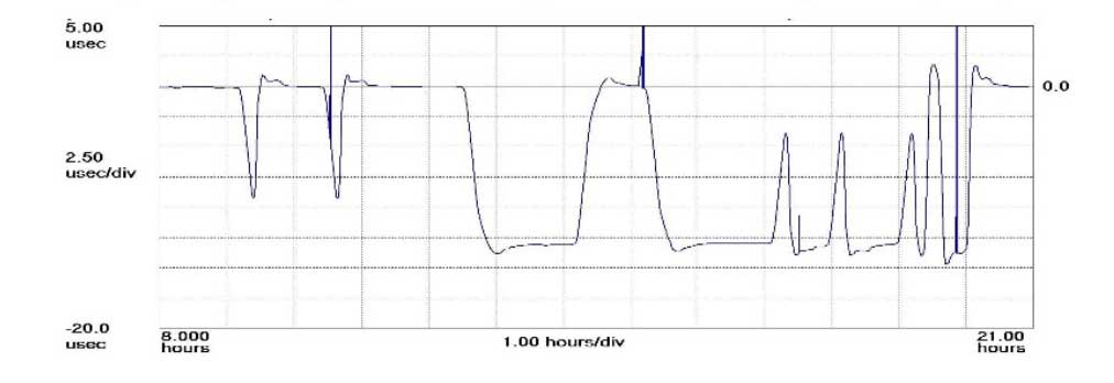
The plot shows how the anomaly event impacted one GPS timing receiver during the day. (Click to enlarge | Chart: Chronos Technology)
“On 26 January at 12:49 a.m. MST, the 2nd Space Operations Squadron at the 50th Space Wing, Schriever Air Force Base, Colo., verified users were experiencing GPS timing issues. Further investigation revealed an issue in the Global Positioning System ground software which only affected the time on legacy L-band signals. This change occurred when the oldest vehicle, SVN 23, was removed from the constellation. While the core navigation systems were working normally, the coordinated universal time timing signal was off by 13 microseconds which exceeded the design specifications. The issue was resolved at 6:10 a.m. MST, however global users may have experienced GPS timing issues for several hours.” (This excerpt from an U.S. Air Force communiqué appears in a brief news account.)
“The Joint Space Operations Center at Vandenberg AFB has not received any reports of issues with GPS-aided munitions, and has determined that the timing error is not attributable to any type of outside interference such as jamming or spoofing. Operator procedures were modified to preclude a repeat of this issue until the ground system software is corrected.”
Companies and their time-servers around the world were subsequently hit by up to 12 hours of system warnings after 15 GPS satellites broadcast the wrong time, according to Chronos, a UK-based time-monitoring firm.
Telecommunications companies constitute only a small part of industry users who rely on the highly precise accuracy of time measurements — supplied by GPS — to control data flow through their networks. Global financial networks and trading markets similarly depend on GPS, as do electrical power grids and many other sectors of critical national infrastructure. These companies and networks invest significantly in highly sophisticated equipment to monitor said timing accuracy as conveyed by GPS signals. Because billions, make that trillions — or actually even more — are riding on it.
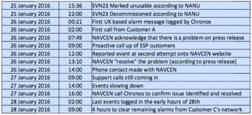
A week after the eye blinks, Chronos Technology released a white paper describing the ensuing fallout for its clients, who are timing equipment users in more than 50 countries around the world. Table 1 from the white paper reports the experience of a few during the event. One company registered nearly 2,500 alarms from its timing equipment during the outage.
Click to enlarge. (Table: Chronos Technology)
At one point during the crisis, according to the white paper, “it appeared that the GPS error had cleared and the Chronos SSP Manager was able to force the units out of holdover. However the scale of the problem escalated as these sites went back into holdover along with dozens of other sites suffering GPS-based timing issues. It was apparent at this point that there was something amiss with the GPS constellation itself.”
Later on, the report states, “This event linked to SVN23 has been one of the most significant service affecting issues for GPS timing users and sits alongside the April 1st 2014 GLONASS outage in scale — however its impact on global timing services is much more extreme.”
Ominously, “Chronos is aware of other more catastrophic impacts to networks and non-telecom applications which were not under supply and support contracts.”
As Loran Is Our Savior. At least one timing-reliant company was not disturbed by the problems, because it was testing an alternative timing service provided by enhanced Loran (eLoran) signals.
Unfortunately for them — and for the rest of us — eLoran has a very uncertain future. In fact, they were lucky to have an eLoran signal at all on January 26, because it was supposed to have been turned off on December 31. Somebody must have forgotten to tell the operators at the Anthorn giant antenna field in Cumbria to go home.
France, Norway, and the United Kingdom, three countries that had been keeping eLoran alive, officially abandoned the effort at the end of last year, reportedly because of lack of leadership from the United States.
The U.S. government decommissioned all its Loran stations a few years ago, even going to the extent of blowing some of them up (perhaps to prevent them from falling into the hands of subversives). Despite a recent reinvigorated interest in enhanced Loran technology, it may be too little, too late.
Whoa, Nellie. The first recorded use of the term “back-up technology” occurred in 1892, when farmers were urged not to prematurely abandon their mules in favor of John Froehlich’s new gasoline tractor.
Dan Albone on his prototype Ivel Agricultural motor. (Image: North Bedfordshire Gazette, 1903)
That admonition, however prudent, has since passed from view. But the concept remains sound. It has surfaced many, many times in GPS World magazine. Certainly not the first incidence, but the farthest back that I can retrieve via search on our website, came in 2007 from Defense contributing editor Don Jewell. “Why do we need a backup? Here is a classic case in point.” He describes a Joint Navigation Conference briefing on a surprise jamming incident that had occurred in January of that year.
In 2009, we reported on an Independent Assessment Team (IAT) report that “unanimously recommends that the U.S. government complete the eLoran upgrade and commit to eLoran as the national backup to GPS for 20 years.” The report was written in 2007, but quashed by the Department of Transportation and Department of Homeland Security (DHS) Executive Committees that commissioned it. Its public release came only after an extensive Freedom Of Information Act (FOIA) battle.
The U.S. government proceeded, despite its paid experts’ recommendations, to blow up those old Loran stations. The current renewed interest and the Wildwood experiment are worthy — more than worthy. Can they prevail? Can they survive blind reliance on a single string of vulnerable technology?
Indubitably, the critical role of GPS back-up was advanced prior to 2007, I just can’t document it this morning by deadline. For the sake of argument, let’s take April 12, 2007, as our start.
We are now 3,229 days out. That’s 77,496 hours, or nearly 279 million seconds. Correct me if wrong, but that appears to make 21.5 million-million times the length of January’s GPS timing error. Surely sufficient to blink a few times, scratch one’s head, and wonder.
Q: What is the optimum number of GNSS signals to include/process in a consumer-grade PNT device?
Daniel Ammann Executive Vice President u-blox Group
A: The cost for including additional silicon to a receiver for processing more signals is low, thanks to multiplexing hardware and high clock speeds. Having more satellite measurements allows the receiver to be selective about which ones it actually uses for PVT calculations, so a number of 30 or higher is desirable. Such a high number, and especially if the signals come from multiple constellations, enables the receiver to have a good view on integrity, too.
Gian Gherardo Calini Head of Market Development European GNSS Agency
A: The answer depends on application and environment where the device will be used. With the increasing need for ubiquitous positioning in difficult environments like urban canyons, the minimum number of satellites from one constellation is not sufficient. The technology makes it possible today to achieve better performance using multiple constellations with low impact on power consumption, and this is where we see the future.
Chaminda Basnayake Principal Engineer Renesas Electronics
A: Demand for more accuracy, availability, and reliability will drive design evolution. Sensor/map augmentations will likely drive system availability while depending on GNSS for better accuracy and reliability. As accuracy is a function of measurement quality and sky view — with the latter fixed for most use cases — placing more emphasis on minimizing errors appears ideal. Therefore, I see dual-constellation, dual-frequency GNSS as the optimal combination and the right balance between complexity versus performance.
Antennas. When I was a kid, antennas meant the pair of rabbit ears sitting on top of the family TV set. We had to constantly adjust the angles to get the best reception, using aluminum foil to improve the signal.
Wow, how things have changed. Today, consumer users of smartphones, Fitbits, smartwatches, tablets and a hundred other electronic devices don’t even think about antennas. Most consumers probably haven’t given a thought to the fact that their favorite device contains an antenna.
Unlike broadcast antennas back in the day, modern GNSS antennas in consumer devices are invisible to the consumer, but perform even in less-than-ideal conditions. Every year brings new improvements and smaller sizes.
Then there are the external antennas, which grow more rugged to withstand the elements while receiving more signals from more constellations, such as BeiDou and Galileo.
GPS World has traditionally published its Antenna Survey in February following the Receiver Survey in January. The first antenna survey appeared in 2001, nine years after we published our first receiver survey. Perhaps it took a few years to realize how critical antennas are in GNSS systems.
As usual, the Antenna Survey encapsulates the important specifications on dozens of antennas, from stand-alone designs for high-precision commercial, defense and timing applications to micro antennas for integration into a variety of smartphones, UAVs and automobiles.
This year, 30 antenna manufacturers provide all the details on their products. Check out the 20-page survey supplement, sponsored this year by NovAtel.
Attention-grabbing graphic from “Navigating Autonomous Requirements” at ION-ITM.
The talk veered off into rather heady philosophical realms at the plenary session for ION’s International Technial Meeting in late January. Two of the three speakers had been encouraged to go well outside the box — and not to employ any equations in doing so — to address or envision the autonomously navigated future.
We are caught in the act of seeing ourselves become obsolete, at least behind the steering wheel of an automobile. The Google driverless car has logged more than a million miles, exploring the traffice terrain that will soon be home to millions of autonomous vehicles. What has it found? That the human in the loop (HiL) is the biggest source of error and catastrophe.
There remain a few technical issues to sort out before this particular future is upon us. One of these, one that excites John Fischer of Spectracom, is the time-sensitive network concept: a standard and securable network that provides a platform for connecting critical system infrastructure with IT features. These networks deal in velocity accuracies of centimeters per millisecond, The V2V and V2X (vehicle-to-vehicle and vehicle-to-network) systems that will support autonomous driving must reduce latency to nearly imperceptible levels for functions like crash avoidance and lane awareness to work reliably.
We were encouraged to consider the ethics of autonomous navigation by Mikel Miller of the Air Force Research Lab, Sensors Directorate. Once the vehicle becomes autonomous, it decides for the driver — including life or death choices.
Imagine a situation that could actually happen less than a decade from now. Riding in a driverless car on a curving coast highway, you round a curve to see a group of children crossing the road. Detecting them, the car begins to brake, but quickly calculates it cannot stop in time. Programmed to avoid collisions with pedestrians and other vehicles, it is also programmed to protect its passengers. It must choose between carnage on the highway or driving you off the adjacent cliff into the ocean.
Which to choose? Four lives versus one. Other ethical dilemmas have arisen in the history of GPS, GNSS, and precise PNT, chiefly concerning privacy. We are about to enter a more difficult realm.
This month’s column recaps UAV news that you may or may not have picked up over the last few weeks. We start with stories related to the rules for operating drones in the U.S., then we’ll look at bird-like drones — used to scare away birds, new commercial UAV applications, and steps being taken to protect us from malicious use of drones and other possible “impacts” of drones.
Who owns the air?
A long time back, the U.S. Congress passed laws which gave the government control above 500 feet and limited land rights so that overflying aircraft could not be considered as trespassing over private property. But, it turns out, ownership of the airspace from the ground up to 500 feet may not be that clear.
The Federal Aviation Administration (FAA) recently reaffirmed that the agency controls all U.S. airspace, even right down to the ground, but it seems that landowners may still have some claim to their own air directly above their property.
In a precedent-setting case dating back to World War II, the U.S. Supreme Court said that landowners have rights to as much airspace as they can use for the enjoyment and use of their land. So if “enjoyment and use” entails flying a UAV at up to 500 feet above their property or alternatively requires no UAVs flying above their own roof-line, who’s rights prevail?
Certainly, there seems to be a number of people who are not too fond of UAVs being allowed to fly over their homes at low altitude. Manned aircraft might be a different kettle of fish as they generally fly higher and don’t seem to bug most people as much. And noise abatement regulations attempt to limit the sound of loud aircraft engines on landing and take-off.
But with this continuing ambiguity, several state and local governments have already begun to take steps to protect airspace over people’s homes.
There are currently more than 150 active bills in more than 30 states — either carried over from 2015 or introduced this year.
Indeed, the FAA, in an effort to dissuade such lawmaking activity, recently released a fact sheet on state and local drone regulations: “Navigable airspace free from inconsistent state and local restrictions is essential to the maintenance of a safe-and-sound air transportation system,” said the FAA. The agency urged local and state lawmakers to consult it before making any new regulations. And it would clearly be far better for drone manufacturers and operators if there was only one set of (FAA) regulations across the whole U.S., rather than each user having to navigate a tangled web of potentially conflicting local and state regulations.
In the meantime, there has been at least one case in which a property owner sought to protect his “home and castle” by unloading a shotgun into a low-overflying drone. The lawsuit was settled to the benefit of the property owner, rather than the drone operator, so property rights did prevail in this case.
Nearly 300,000 owners have registered their small unmanned aircraft (sUAV) in the first 30 days using the FAA’s online registration system and have received a refund for the $5 application fee. While the refund period has now expired, the agency continues to see a steady stream of daily registrations.
The FAA’s registration rule, which took effect on December 21, 2015, applies to sUAV that weigh between 0.55 lbs. and 55 lbs. Existing owners of these aircraft must register before Feb. 19, 2016. The current online system only supports use by recreational or hobby operators, while the FAA hopes to provide commercial operators with access by March 21.
Name, address and email are required ,and a registration number and printable certificate are then provided. The registration number must be marked on the UAV.
A drone flies in Russia.
Meanwhile, Russian President Vladimir Putin has signed a law that obliges all private owners of unmanned aircraft weighing more than 250 grams to register them with the Federal Air Transport Agency.
According to the new act, which comes into force at the end of March 2016, owners and operators of unmanned aircraft systems (UAS) must also appoint a crew and a commander responsible for flight safety. In order to operate, a flight plan must be submitted to the regional air traffic controllers — as required for manned aircraft operations — and the flight plan has to be followed unless an emergency landing is necessary when there is a threat to public safety.
Is that a bird or a drone?
But, of course, the more we try to overcome issues related to UAVs, the more complicated it seems to become. A core element of all FAA authorizations to date has been that a drone should never be operated within several miles of an airport to avoid collisions with aircraft. Now, a company has come up with a drone which carries a broadcast sound unit, programmed with a number of hawk, owl and other bird calls — ideal for scaring feeding or roosting birds away from areas we want to clear, such as at airport runways.
Bird strikes by aircraft in the critical phases of landing or take-off are a major concern for airlines and airports alike. Many methods have been tried to reduce birds flying around at the sound of loud aircraft noise. Birds can get sucked into engines or can damage other critical aircraft structures. Air blasts that sound like shotguns and flying live falcons are only a couple of methods used to clear birds away from airport approaches, departures and runways.
Bird-repelling drone.
In the meantime, at least one enterprising associate prof at the University of Illinois has recognized the requirement and is developing a robotic falcon that chases birds away from airfields.
A flying falcon.
Soon-Jo Chung and his team have been supported by funding not only by the National Science Foundation’s CAREER Award program to create the flying falcon above, but also by other sources to develop vision-based navigation. An analytical computer simulation has replicated motion control and avoidance so the robotic falcon can intelligently come up with motion planning algorithms.
And another the twist to this story is that bald eagles and other birds of prey are being trained to hunt and take down drones in the Netherlands. Dutch police have been investigating this natural “anti-drone technology” to combat criminal use of drones, and to counter the prospect of drones being used to deliver bombs or chemical and biological weapons.
UAV inspection/monitoring to reduce costs and enhance safety
A DJI UAV was recently used by Lufthansa Aerial Services to inspect rotor blades on wind turbines. Previously, inspection was somewhat dangerous, and required climbing the wind turbine tower. While cost reduction may be the principle motivation, it’s possible that wind turbine inspection and maintenance periods could also be extended.
And, in partnership with Flot Systems, Xcel Energy has become the first utility company to use drones in beyond-line-of-sight inspection of more than 320,000 miles of electricity and natural gas infrastructure.
Xcel began using UAVs to visually inspect substations in 2015, and is one of the first operations to receive FAA approval for research to use “beyond visual line of sight” for these inspections.
Previously, manned helicopters were contracted that would carry an inspector and would fly along transmission lines. But from a safety viewpoint, flying UAVs near high-voltage lines is less risky for workers and pilots. Transmission line inspectors also used to have to walk through difficult terrain which can also be hazardous.
(Editor’s note: Look for more information on UAV’s used for utility inspections in the March issue of GPS World.)
Another major area that can benefit from the use of drones is agriculture. Remote crop inspection through live and recorded video helps farmers gather much better information to support improved crop growth.
A Hermes 450 may be gathering lots of usable growing crop information this summer, provided an ag project in North Dakota is approved. The UAV can carry up to 400 pounds of sensors and cameras, and collects data at around 92 mph for 14 hours at 8,000 feet, covering 50,000 acres per hour.
Photos and videos of growing corn, sugar beet and other crops have the potential to identify fertility deficiencies, yield estimates, and weed and disease issues. North Dakota State University (NDSU) is collaborating with the Northern Plains UAS Test Site and Elbit Systems of America to conduct the crop project.
The operation is planned to cover a whole county in North Dakota, mostly outside line-of-site of the operator, so in this case a manned aircraft is needed to observe the UAV — it’s a safety condition of the FAA Section 333 approval. Many producers in North Dakota are already buying, registering and flying their own smaller UAVs.
And one drone operator is taking a pro-active approach to help the agriculture industry decide if using drones can help them. Working with the American Farm Bureau Federation, on behalf of several major sponsors, Measure has released what it calls the Drone Flight Calculator.
The Drone Flight Calculator quantifies the economic benefits of using drone services for crop monitoring — such as soy, corn or grapes. When data such as fertilizer use, farm size, and crop type are entered, the calculator provides economic returns by acre and for each growing season. Farmers can also learn how much they can expect to save on inputs such as fertilizer and irrigation.
Drone flies into hurricane
The National Oceanic and Atmospheric Administration (NOAA) has been working with several UAVs to investigate the tracking and modeling of hurricanes. NOAA successfully deployed a Coyote UAV from a P-3 hurricane hunter aircraft into the eye of Hurricane Edouard in the fall of 2014. The Coyote is a small, expendable UAS that can be tube-launched from an aircraft or from the ground.
The seven-pound unmanned aircraft was deployed from a free-fall chute in the belly of the plane, which then opened its six-foot wingspan to fly through the storm. It can be controlled from miles away, but was piloted by scientists onboard the P-3.
A successful calibration flight over Avon Park, Florida, was recently completed, where a Coyote was launched from a P-3 hurricane hunter aircraft to prepare for deployment during storm season.
“This successful flight gives us additional confidence that we will be able to use this unique platform to collect critical continuous observations at altitudes in the storm environment that would otherwise be impossible,” said Joe Cione, a hurricane researcher at NOAA’s Atlantic Oceanographic and Meteorological Laboratory and chief scientist of the Coyote program.
With a particularly military look to it, a consortium of British companies has come up with a system to defeat potential attacks using drones. Dubbed the Anti-UAV Defence System (AUDS), it combines electronic scanning air security radar, a stabilized electro-optic director, infrared and daylight cameras, target tracking software, and a directional radio frequency (RF) inhibitor/jammer system.
Anti-UAV Defence System (AUDS).
The portable system can spot small, slow-moving drones up to four miles away using radar. A military-grade camera then tracks it before jamming the radio signals that control it, making it impossible to fly. The whole process can take as little as 15 seconds.
With incidents of drone-related security breaches occurring regularly, there is a need to address heightened UAV concerns within military, government, critical infrastructure and commercial security organizations. While UAVs have many more positive applications, it’s nevertheless anticipated that they could also be used for terrorism, espionage and smuggling — with cameras, weapons, toxic chemicals, explosives and drugs as potential payloads.
The AUDS technology has apparently been extensively tested in South Korea, at French government trials and in UK government-sponsored counter-UAV trials.
In fact, this system or one very much like it underwent a successful trial at London’s Remembrance Day parade. The system was installed on the roof of Scotland Yard, close to where the Nov. 11 ceremonies took place. Police in the UK are apparently looking for such a device to block drones flown by terrorists at major public and sports events.
Along the same lines, Drone Labs has developed a Drone Detector unit that appears to use audio and radio frequency sensors along with GPS to find not only a drone, but also the location of the operator, over at least a range of 1 kilometer.
Drone Labs plans to add video, thermal and radar detection capabilities. The object is to provide some level of protection from drones used for illegal activities, such as delivering contraband at prisons. Some operations already using the system include movie sets, celebrities and facility management professionals seeking to protect assets and people from intrusive drones, as well as law enforcement. Presumably, criminals might also use such a system to reduce the risk of detection by law enforcement drones.
Crashing drone nearly hits skier
And, while it’s good that we put attention on protecting us from potential drone attacks, it’s unfortunate that we recently witnessed live TV coverage of a drone crash that could have had really bad consequences. In December, one of world’s best Alpine skiers was lucky not to be taken out by a crashing drone carrying a TV camera during a slalom run in Italy. Unfortunately, following the incident, the International Ski Federation (IFS) went on to ban camera drones from its World Cup races.
IFS’s broadcast partner — Infront Sports and Media — has indicated the likelihood that the control link to the UAV may have been lost, possibly due to radio interference. Infront has decided to engage an external independent expert to formally investigate the incident. IFS noted that the drone operator had agreed to maintain a safe 15-meter distance from the ski slope. However, it’s possible this safety margin was not maintained…..err, well, it would seem so! The drone fell directly onto the ski slope!
So, maybe it was some over-zealous operator error along with a technical failure — this can happen with any technology — but hopefully no active jamming was involved. For one, I was happy that nothing broke on the overhead camera-carrying wire-system following the action on the field at the Super Bowl this weekend! (It wasn’t such an exciting game in the end anyway.…)
Almost every day, news about UAVs continues to pour in with updates on regulation, legal aspects of drone operations, new ways to reduce costs by applying drones to an existing task, and privacy and security angles on why and when something should or shouldn’t be done with an unmanned air vehicle. It’s interesting to watch how things develop in this new industry — almost like when GPS was brand-new and just getting started…
In September 2013, the night before he won the prestigious ION Kepler Award, Dr. John Betz and I were enroute to an ION (Institute of Navigation) dinner when he casually mentioned that he was thinking about writing a book. The natural journalistic inquiries about subject and timing brought a surprising response. The draft of the first chapter was already complete and it would be about PNT space systems or GNSS (Global Navigation Satellites System) if you will. Not just GPS, but all space-borne (satnav) PNT (position, navigation and timing) systems and augmentations.
When I asked John exactly why he was writing the book he replied, “I am writing the book for several reasons. First, there is a shortage of books that uniformly treat all satnav systems, rather than emphasizing a single system. There are a lot of common and complementary characteristics that become clear when all are treated in a uniform and consistent way.
“Second, this is a chance to provide an integrated perspective on satnav systems engineering. Lastly, I’ve learned a lot in the last 17 years, and I want to document it in an organized way.”
I, of course, offered to help in any way I could. I mentioned that I would very much like to review the book when it was finished. Not too much was said about the book until the next year at the very same event, when John mentioned the book would be ready for publication in the first quarter of 2016. Again I offered to review the book, and this column is that promised review.
First of all, there can be no doubt that Dr. John Betz, a MITRE Fellow, is qualified to author this engineering tome about all matters pertaining to space-borne PNT. Indeed, if I were to fully recite his impressive curriculum vitae, it would be longer than the entire space allocated for my column, so I will make do with the short paragraphs that accompanied the Kepler Award.
Dr. John Betz, winner of the ION 2013 Kepler Award.
“Dr. John Betz contributed to the international interoperability and compatibility efforts leading to the design of the GPS L1C civil signal. His Binary Offset Carrier (BOC) technique is used for the GPS M-code signal, and adopted by satellite navigation systems developed by Russia, Europe, China, Japan and India.
“Since 1997, Dr. Betz has worked on the NAVSTAR GPS and also on international negotiations concerning compatibility and interoperability of GPS with the world’s satellite navigation systems. For his role in the United States/European Union negotiations that established compatibility and interoperability between GPS and Galileo in 2004, he received the U.S. State Department’s Superior Honor Award.
“More recently, Dr. Betz provided critical analysis related to GPS modernization, recommending affordable enhancements to address increasing threats and to shape the architecture of military GPS for decades to come. Col. Bernard Gruber, [then] director of the GPS Directorate said, ‘I can think of no one else in the past two decades, military or civilian, who has influenced this critical national asset to the same degree as Dr. Betz’.”
I asked Dr. Betz what he liked most about writing the book, what he disliked the most, and would he do it again?
“Don, some chapters just flew — it was really fun to write them,” he said. “And I really like the color graphics, even in the print edition. It was challenging to find the time, given my work schedule. That was probably the most difficult part. It’s amazing when I look back. It was a little more than two years from start to submitting the manuscript. I had planned on 400 pages and it’s 640 pages. And yes, I would do it all again.”
Scope
The scope of this engineering reference is exhaustive in nature where PNT is concerned. The work is balanced between original content and a compilation of academic papers by numerous expert authors. Certainly, Dr. Betz gives credit where credit is due; he often recommends other volumes, texts and papers for enlightenment. However, for me his personal and professional insights and clear explanations of highly technical issues are what make this a compelling volume.
In his introduction, Dr. Betz describes his effort:
“This book describes satellite-based navigation and timing (satnav), the engineering of systems that transmit radio frequency (RF) ranging signals from a constellation of satellites so that a passive receiver can determine time and its position. The intent of this book is to provide a consistent and integrated depiction of the engineering behind satnav.”
If a PNT or GNSS constellation, or even a small group of satnav vehicles, is in orbit today — such as WAAS, EGNOS and QZSS — John describes their makeup and contribution to the overall PNT solution in great detail that is understandable to both the academic and layman alike.
Insights
I have personally been involved with satnav in one fashion or another for 40 years. Frankly, I thought I was well versed in the subject. Yet, in every chapter of John’s book, I either learned something new or had an issue explained that I obviously did not understand quite as well as I thought. There is something for everyone interested in satnav in this wonderful book, regardless of their level of involvement or sophistication with PNT.
References
The book contains exhaustive tables, references, figures and formulas for all levels, which is why I am sanguine this book will become an invaluable reference and textbook for the military as well as any university dealing with educating students concerning satnav and PNT issues.
When I finished reading the 640-page volume, I had added more than 40 blue “stickies” to mark figures or tables for future reference.
This book is a treasure trove for PNT engineers and satnav experts, but it’s readability is such that even if you are only slightly curious about how space-based PNT works, you will find it an educational and enjoyable read.
For instance, on page 29, Table 2.1 summarizes the nominal constellation characteristics, 16 for each system, between GPS (US), GLONASS (Russian), Galileo (European) and the BeiDou (Chinese) constellations. While this will probably only serve as riveting cocktail repartee at something like an ION function, it is also just good to know, fun facts if you will. It might even serve as a Jeopardy category one day.
Bottom Line
Dr. Betz begins his lengthy but enjoyable tome with an explanation of satnav; takes the reader through the various space-borne PNT systems and augmentations on orbit today; describes the signals, the errors and the various pluses and minuses of each system; and then delves into PNT receiver design and describes how each signal is received and utilized.
After reading the book I asked Dr. Betz if he thought or hoped the book would be used as a textbook. He replied, “I hope it gets used in multiple ways. It can certainly be used by practicing engineers as a reference and for in-depth exploration. I hope its contents and structure make it useful as a textbook, because the book includes theoretical and applied questions at the end of many chapters that should help students learn how to extend and apply the theory and practice laid out in the book. Also, I hope its structure is conducive for use in teaching.”
While the jury is still out on whether this is a engineering textbook, a satnav reference manual, a primer on modernized PNT, or perhaps a compendium of all three, if you care at all about modern-day GNSS and all it enables, this book should be in your library.
Until next time, happy navigating, and I hope you enjoy the book.
When I entered the civilian part of my GIS career as the GIS manager for the Atlanta Regional Commission, I tried to get first responders interested in GIS. Of course, in the early ’90s we were happy to be able to accurately draw points, lines and polygons on a piece of paper. Soon we had the luxury of ortho imagery as a backdrop for our GIS data, but I still couldn’t build a lot of enthusiasm among those first responders.
That changed completely when we started using metric oblique imagery provided by Pictometry. I realized that since we live in an oblique/3D world many non-GIS users had real difficulty visualizing objects or locations using two-dimension visualizations such as drawings, blueprints, maps or even ortho imagery.
By contrast, oblique views made visualization much easier for the vast majority of non-GIS users, and use of oblique imagery coupled with GIS tools exploded. Since then, many of us have been searching for faster, easier and cheaper ways to collect oblique imagery and video, and build 3D models.
For more than a decade, major defense contractors developed leading-edge systems to capture and exploit aerial imagery and video. Although effective, as one would expect of new custom technology, the systems were very expensive and out of reach for most local government agencies. Remote GeoSystems seems to have developed a system that leverages current technology to provide capabilities that may address some of those needs at a reasonable price.
Remote GeoSystems is in the business of capturing, displaying and managing “georeferenced” video and imagery. The company has designed and built high-end geospatial video recording systems for full motion video (FMV) and GIS mapping software primarily aimed at regulatory compliance of energy corridors, grids and critical infrastructure inspection applications.
Fortunately, my UAV is a DJI Inspire 1. I chose the Inspire because of its reputation, and because it seems to be the best combination of features needed for first-responder work at a prosumer price (about $3,500). The Inspire can record up to 4K video/12-mp stills, has a 94-degree field of view so there is no wide angle “fish-eye” distortion typical of an action camera, and has “Lightbridge” technology that permits positive control up to 3 miles and the ability to stream live 720p video (now 1080p) back to the ground controller.
The controller can feed large-screen video for command center group viewing via an HDMI output. Most important, the Inspire records GPS position data and altitude along with the video/imagery stream. (The DJI Phantom 3 Pro is a cheaper alternative that also records telemetry data, but if one upgrades to a 4K camera and the Lightbridge transmitter/receiver, the price approaches the integrated Inspire 1 price.)
An .srt file.
Since I’m always leery of marketing pieces and company demos, I wanted to try the system myself, and Remote Geo was happy to oblige. My first hands-on test was very satisfying. The LineVision software downloaded, unpacked and loaded quickly with no problems. I then recorded some aerial video of our condo building on Lake Guntersville near Huntsville, Alabama. I chose this building because it was convenient, safe to fly and a multi-story building in the open.
In addition to recording the video, one needs to turn on the DJI Inspire metadata recording to generate the .srt file. This is done in the DJI application “General Settings/Camera” by toggling “Video Caption” on. The .srt file was initially designed to provide altitude and location data as on-screen captions, but the data can be used as needed for other purposes.
When done with the flight and recording, transfer the video file and .srt file to your computer. Make sure the video file .mov/.mp4 and .srt file are in the same folder. Open LineVision and you will see an ArcGIS window. From the pull-down menu, load the video and you will instantly see the video play in a separate window with red position dots on the ArcMap view. As the video plays, the dot associated with the location of the UAV will turn yellow. If you click on any dot, the video will jump to that location/position on the video.
Here are screen captures of LineVision showing the ArcGIS view of an ortho image with red dots illustrating the path of the UAV:
One advantage of LineVision for first responders is that it is a complete package with ArcGIS embedded, all for a price well below $1,500. There is no need for a separate ArcMap license. Additionally, although LineVision Esri ArcGIS can display GIS data from online sources, if you have GIS data for your location loaded on your computer the system will operate in a disconnected remote environment. These sample screengrabs don’t do the system and video justice, since I recorded at 1080p rather than 4K. My laptop, this website and the reader’s playback equipment limit accurate playback of 4K content, so I did my work at 1080p.
I can envision a disaster-response scenario where the response team arrives on site, launches a UAV, and starts recording the scene. The captured video could then be loaded, viewed, indexed and cataloged with GIS data overlays on a laptop all in a matter of minutes, even in a disconnected environment. Hours, days or months later, finding the right video clip for analysis or forensics should be significantly easier and faster.
With the explosion of UAV hardware and software, it’s going to be an exciting year as new smaller, cheaper and more capable systems hit the market. Remote GeoSystems is working with UAV manufacturers to make LineVision capability available for many of the newcomers.
Leveraging UAV and LineVision capability, Skyline has worked with Remote GeoSystems to bring yet another capability: rapid 3D model creation. Taking appropriate geo-located frames of the video, Skyline uses its PhotoMesh software to build fully metric 3D models in short order. The full capability of this system and its 3D viewer TerraExplorer is so extensive that I will cover it in a future column, after this month’s ESRI Federal Users’ Conference. If you see me at the UC Feb. 24-25, please stop me and say hello.
Basic procedures and tools for ensuring GNNS-derived orthometric heights meet the project’s desired accuracy
So far, this series of columns has addressed the following topics: basic concepts of GNSS-derived heights (Part 1), National Geodetic Survey’s (NGS) guidelines for establishing GNSS-derived ellipsoid heights (NGS 58) (Part 2), differences between hybrid and scientific geoid models (Part 3), and procedures and tools for detecting GNSS-derived ellipsoid height data outliers (Part 4).
These four columns were meant to provide the reader with basic concepts and procedures for estimating GNSS-derived ellipsoid heights and understanding hybrid and scientific geoid models. Now that the reader has a basic understanding of GNSS-derived ellipsoid heights and geoid models, this column will discuss procedures for estimating GNSS-derived orthometric heights.
Determining valid North American Vertical Datum of 1988 (NAVD 88) published heights is the most important process when using GNSS data and geoid models to estimate GNSS-derived orthometric heights. As mentioned in Part 4, NGS has developed procedures for estimating GPS-derived orthometric heights and these guidelines are documented in NOAA Technical Memorandum NOS NGS 59. The NGS 59 guidelines are separated into three basic rules, four control requirements, and five procedures that need to be adhered to for computing accurate NAVD 88 GNSS-derived orthometric heights. This column will address the NGS 59 guidelines and methods for evaluating the results of the GNSS project.
The three basic rules are fairly simple to understand and implement, provided that the reader has followed the previous columns in this series.
Three Basic Rules for Estimating GNSS-Derived Orthometric Heights:
Rule 1: Follow NGS 58 guidelines for establishing GNSS-derived ellipsoid heights when performing GNSS surveys (Parts 2 and 4 addressed this rule),
Rule 2: Use NGS’ latest National hybrid geoid model (such as GEOID12B) and latest experimental geoid model (such as xGeoid15B) — when computing GNSS-derived orthometric heights (Part 3 addressed this rule), and
Rule 3: Use the latest National Vertical Datum — for instance, NAVD 88 — height values to control the project’s adjusted heights (this column will address this rule).
The four basic control requirements are also simple, but, in certain regions of the country, may be difficult to implement.
Four Basic Control Requirements for Estimating GNSS-Derived Orthometric Heights:
Requirement 1: GNSS-occupy stations with valid NAVD 88 orthometric heights; stations should be evenly distributed throughout project.
Requirement 2: For project areas less than 20 km on a side, surround project with valid NAVD 88 benchmarks, i.e., minimum number of stations is four; one in each corner of project. [NOTE: The user may have to enlarge the project area to occupy enough benchmarks, even if the project area extends beyond the original area of interest.]
Requirement 3: For project areas greater than 20 km on a side, keep distances between valid GNSS-occupied NAVD 88 benchmarks to less than 20 km.
Requirement 4: For projects located in mountainous regions, occupy valid benchmarks at the base and summit of mountains, even if the distance is less than 20 km.
Figure 1 depicts the NCGS Rowan County Height Modernization project discussed in Part 4. Looking at Figure 1, there are stations with published leveling-derived NAVD 88 orthometric heights distributed throughout the project (requirement number 1).
What do I mean by published leveling-derived NAVD 88 orthometric heights? This is important to note because all NGS datasheets provide the NAVD 88 height with an attribute that describes what method was used to establish their height. The following is a list of attributes used on the NGS datasheet for NAVD 88 published heights:
There are various Vertical Control sources, as specified below:
ADJUSTED = Direct Digital Output from Least Squares Adjustment
of Precise Leveling. (Rounded to 3 decimal places.)
ADJ UNCH = Manually Entered (and NOT verified) Output of Least Squares Adjustment of Precise Leveling. (Rounded to 3 decimal places.)
POSTED = Pre-1991 Precise Leveling Adjusted to the NAVD 88 Network After Completion of the NAVD 88 General Adjustment of 1991. (Rounded to 3 decimal places.)
READJUST = Precise Leveling Readjusted as Required by Crustal Motion or Other Cause. (Rounded to 2 decimal places.)
N HEIGHT = Computed from Precise Leveling Connected at Only One Published Benchmark. (Rounded to 2 decimal places.)
RESET = Reset Computation of Precise Leveling. (Rounded to 2 decimal places.)
COMPUTED = Computed from Precise Leveling Using Non-rigorous Adjustment Technique. (Rounded to 2 decimal places.)
GPSCONLV = Leveled Orthometric Height tied to GPS HT_MOD Orthometric Height. (Rounded to 2 decimal places.)
LEVELING = Precise Leveling Performed by Horizontal Field Party. (Rounded to 2 decimal places.)
H LEVEL = Level between control points not connected to benchmark. (Rounded to 1 decimal places.)
GPS OBS = Computed from GPS Observations. (Rounded to 1 decimal places.)
VERT ANG = Computed from Vertical Angle Observations. (Rounded to 1 decimal place; If No Check, to 0 decimal places.)
SCALED = Scaled from a Topographic Map. (Rounded to 0 decimal places.)
U HEIGHT = Unvalidated height from precise leveling connected at only one NSRS point. (Rounded to 2 decimal places.)
VERTCON = The NAVD 88 height was computed by applying the VERTCON shift value to the NGVD 29 height. (Rounded to 0 decimal places.)
During the design of the survey, the user should first select as many stations with the attribute of ADJUSTED or LEVELING. If there aren’t any stations in a certain area of the project with the attribute of ADJUSTED or LEVELING, then stations labeled as GPS OBS with values rounded to 2 decimal places should be occupied. The other types of NAVD 88 heights aren’t accurate enough to validate your GNSS results.
Looking at Figure 1, there appears to be a few void areas in the north and east sections of the project. Although, it should be noted that the design meets the 20 km spacing rule (Rule number 3). Figure 2 depicts the NAVD 88 published heights for all leveling-derived stations and GPS-derived orthometric heights published to two decimal places (i.e., cm level). The published GPS-derived orthometric NAVD 88 heights filled in the void areas of the project. This is the practical reality of implementing the guidelines of NGS 59.
In some areas of the United States it may be difficult to locate enough valid NAVD 88 heights in the project’s area. First, let’s define a valid NAVD 88 height. Valid NAVD 88 height values include, but are not limited to, the following: control points which have not moved since their heights were last determined, were not misidentified, and are consistent with NAVD 88. This appears to be fairly simple, but it may be difficult for some users to determine if a station has moved since the height was last determined. In addition, in some areas of the country the user may not find valid NAVD 88 benchmarks every 20 km due to crustal movement. The user then may have to perform some classical precise leveling observations to evaluate the existing NAVD 88 heights and determine the relative accuracy of the geoid model in the areal extent of the project.
This doesn’t mean that the user must perform a leveling survey such that all GNSS stations are leveled to or even perform a large leveling network survey. The purpose of the leveling is to evaluate the geoid model and properly connect to the NAVD 88. Since each case is difference, i.e., NAVD 88 height problems and geoid accuracy will vary in each region of the country, as well as each individual project accuracy requirement will be different, it is impossible to describe exactly what the user will have to do. NGS will, however, assist users when they’re planning their surveys. You can contact a NGS advisor through their Regional Advisor Program.
The five basic procedures for estimating GNSS-derived orthometric heights may appear to users to be the most complex and most difficult to understand. However, as users perform more GNSS surveys and discuss their results with others, they seem to quickly understand why these procedures are needed.
Five Basic Procedures for Estimating GNSS-Derived Orthometric Heights:
Procedure 1: Perform a 3-D minimum-constraint least squares adjustment of the GNSS survey project, i.e., constrain one latitude, one longitude, and one orthometric height value. This procedure was described in Part 4.
. Procedure 2: Using the results from the adjustment in procedure 1, detect and remove all data outliers. (NOTE: If the user follows NGS’ guidelines for establishing GNSS-derived ellipsoid heights (NGS 58), the user will already know which vectors may need to be rejected and following the GNSS-derived ellipsoid height guidelines should have already re-observed those base lines.)
The user should repeat procedures 1 and 2 until all data outliers are removed.
Procedure 3: Compute the differences between the set of GNSS-derived orthometric heights from the minimum constraint adjustment (using the latest National geoid model, for example GEOID12B, and National experimental geoid model, for example xGeoid15B) from procedure 2 above and the corresponding published NAVD 88 benchmarks.
Procedure 4: Using the results from procedure 3, determine which benchmarks have valid NAVD 88 height values. This is the most important step of the process. Determining which benchmarks have valid heights is critical to computing accurate GNSS-derived orthometric heights. (NOTE: The user should include a few extra NAVD 88 benchmarks in case some are inconsistent, i.e., are not valid NAVD 88 height values.)
Procedure 5: Using the results from procedure 4, perform a constrained adjustment holding one latitude value, one longitude value, and all valid NAVD 88 height values fixed.
As mentioned in Part 4, during the analysis of the GNSS-derived ellipsoid heights, the user needed to perform a minimum-constraint least squares adjustment and look for outliers. This ensures that the GNSS-derived ellipsoid heights meet the user’s desired standards. Now, the user must ensure that the NAVD 88 heights that are going to be used to control the final set of GNSS observations and geoid heights are valid.
Part 4 described in detail how to analyze the project’s ellipsoid heights. If the user followed the procedures outlined in Part 4, then procedures 1 and 2 were performed.
The techniques described below are meant to be fairly simple for users to implement. They are not rigorous and are not the only way to detect outliers. They will, however, assist the user in determining which NAVD 88 benchmarks are valid. Procedure 3 is simply computing the GNSS-derived orthometric heights and comparing the results with the published leveling-derived NAVD 88 heights. The set of GNSS-derived orthometric heights are obtained by performing procedure 1. Figures 3 and 4 provide the differences between the GNSS-derived orthometric heights using GEOID12B and published leveling-derived NAVD 88 orthometric heights. (NOTE: One station’s latitude, longitude, and orthometric height (Buffalo 2) was constrained in the minimum-constraint least squares adjustment. Since any of the stations with a published height could have been constrained in a minimum-constraint least squares adjustment, an average difference (a bias) computed using all of the differences was removed from each difference.)
All relative height differences between adjacent station pairs should agree within 2 cm for 2-cm surveys and 5 cm for 5-cm surveys to be considered valid NAVD 88 benchmarks. Relative height differences that do not meet this guideline should be investigated.
Part 3 discussed the difference between hybrid and scientific geoid models and that the user should use both models during their analysis of GNSS surveys. As mentioned above, Figures 3 and 4 provided the difference using GEOID12B; Figures 5 and 6 provide the differences using xGeoid15b. Tables 1 and 2 provide this information in tabular form.
Table 1. Differences between GNSS-derived orthometric heights from a minimum-constraint adjustment (using GEOID12B) and published NAVD 88 heights (GEOID12B results sorted and highlighted).Table 2. Differences between GNSS-derived orthometric heights from a minimum-constraint adjustment (using xGeoid15b) and published NAVD 88 heights (xGeoid15b results sorted and highlighted).
The reader should note that most differences in Figure 3 are less than 2 cm, but there is a several differences greater than +/- 2cm. Eight stations have differences greater than +/- 2 cm [see Table 1, column labeled “GNSS-Derived Orthometric Height (using GEOID12B) minus Published NAVD 88 Height (cm)”]. These stations should be investigated as a potential outliers.
Looking at Figure 3, the reader should notice that several stations less than 20 km apart have a relative differences greater than 4 cm.
For example, the following three station pairs have large relative height differences: [Buffalo 2 (AB6805) – Phaniel (AB6836): 4.9 cm], [V 49 (FA0151) – Phaniel: 5.6 cm], and [Row 9 (DG5715) – Phaniel: 5.7 cm]. To investigate this further, we need to introduce the scientific geoid model in the analysis. Figures 5 and 6 are plots of the differences using xGeoid15b. The user should notice that the relative differences using the scientific geoid model (Figure 5) between the same stations pairs are all less than the differences using GEOID12B (Figure 3).
For example, the relative differences between Phaniel and Buffalo 2 is 4.9 cm [(2.8 – (-2.1)] using the GEOID 12B geoid model. The relative differences between the same two stations using xGeoid15b is only 0.7 cm [4.2 – 3.5]. This implies that the hybrid geoid model may have been distorted to agree with stations that may have moved since the last time they were observed. This could be an indication that station Phaniel and/or Buffalo 2 may have moved since they were last surveyed. If so, once again, they should not be constrained in the final adjustment.
It should also be noted that only five stations have differences greater than +/- 2 cm using xGeoid15b [see Table 2, columns labeled “GNSS-Derived Orthometric Height (using xGeoid15b) minus Published NAVD 88 Height (cm)”]. However, the five outliers are significantly larger than the rest of the differences (see highlighed section on Table 2). All other differences using xGeoid15b are less than +/- 1.7 cm. These five leveling-derived heights should be investigated for possible movement before constraining their heights in the final adjustment.
As previously mentioned, looking at Figures 5 and 6, stations Phaniel and Buffalo 2 seem inconsistent with the other stations in the southern half of the project. Another potential outlier highlighted in Table 2 is station Row 3 with a difference of -3.8 cm. These stations should definitely be investigated for potential movement.
When performing constrained GNSS-derived orthometric height adjustments, it is important to determine the effect of the constraints on the adjusted heights of the unconstrained stations. If a station’s published height is not valid, then constraining that value could distort the final set of adjusted coordinates. Users should compare the differences between the adjusted heights from the constrained adjustment with the adjusted heights from the minimum-constraint adjustment. Figures 7 and 8 are plots that depict the differences between the adjusted heights obtained from a fully constrained adjustment (using GEOID12B) and a minimum-constraint adjustment.
Looking at Figures 7 and 8, the reader should notice that several of the heights of stations in the southern portion of the network have changed by more than 3 cm. More importantly, some of the closely spaced stations have large differences in relative height changes. For example, the adjusted height at station Phaniel changed -4.9 cm (this station was constrained) and its neighbor station Moose (4 km from Phaniel) only changed -3.1 cm. This means the constraint changed the height difference between Phaniel and Moose by 1.8 cm. If the constraint is valid, then the user should use it in the constrained adjustment. However, during our analysis of this project, we identified station Phaniel as a potential outlier which means that station Phaniel may have moved since it was last surveyed. As previously mentioned, if a station moved since it was last surveyed it should not be constrained because it may distort the adjusted heights around it. Saying that, it is important to maintain consistency in a National Vertical Control Network, e.g., NAVD 88, when incorporating survey data into the network. If the station is not constrained and it did not move since it was last surveyed, then all stations surrounding the superceded station will be inconsistent with its neighbors. Therefore, if a user cannot determine that the station has moved since it was last surveyed, it should be constrained in the final adjustment.
To determine the effect of constraining station Phaniel, another constrained adjustment was performed constraining all published NAVD 88 leveling-derived orthometric heights except for station Phaniel. Figures 9 and 10 are plots that depict the differences in adjusted heights due to constraining all published NAVD 88 leveling-derived orthometric heights except for station Phaniel. The plots indicate that by not constraining Phaniel, the changes in adjusted heights due to that constraint were all reduced. All differences in the area of station Phaniel are less than 3 cm and the relative height changes have been significantly reduced. For example, the relative height change involving station Phaniel and Moose was reduced from -1.8 cm [-4.9 – (-3.1)] to -0.2 cm [-1.9 – (-1.7)], and from station Phaniel to Cold, the relative height change decreased from -2.9 cm [-4.9 – (-2.0)] to -0.6 cm [-1.9 – (-1.3)]. (See Figures 8 and 10.) This is a reason why it is very important to determine if a station’s published height is still a valid NAVD 88 height.
This column discussed procedures for estimating GNSS-derived orthometric heights following NGS 59 guidelines. It provided methods for evaluating the results of the project and identifying stations with valid NAVD 88 published heights. More analysis needs to be performed to identify all the valid stations to be constrained in this project. In the next column, we will continue to analyze the changes in adjusted heights due to different constraints, compare the results to the published NAVD 88 GNSS-derived orthometric heights observed in this project, and investigate the leveling network used to establish the published NAVD 88 leveling-derived orthometric heights.
For most GIS professionals, Esri’s new ArcGIS Earth will replace the soon-to-be-discontinued Google Earth Enterprise. I take a tour through the new software, which is much like Google Earth with a few added features. Plus: Q&A from our December UAV webinar.
In early 2015, Google announced that Google Earth Enterprise is being deprecated. In the software world, deprecated means the software is heading towards obsolescence and the vendor isn’t going to develop it further.
Google’s announcement stated that Google Earth Enterprise was being deprecated as of March 20, 2015, but will be supported through March 22, 2017. According to Esri, Google will continue to provide map and location services APIs as well as content.
Here comes Esri, introducing ArcGIS Earth.
At the Esri User Conference last summer, Jack Dangermond announced Esri is working on ArcGIS Earth. Last week, Esri announced the introduction of ArcGIS Earth 1.0. You can download ArcGIS Earth for free.
The opening screen looks a lot like Google Earth, but clearly with an Esri touch via the toolbar in the upper left corner.
You can connect to ArcGIS Online and access its library of data, or import SHP and KML data (no TIF/TFW import, though).
Here are the convenient editing and querying tools (measure).
I imported a KML file containing an orthophoto I created from a UAV flight. Sorry for the orthophoto offset (darned horizontal datum thing).
As it stands now, ArcGIS Earth 1.0 is much like Google Earth with a few added features. However, based on what I perceive Jack Dangermond’s mantra to be, ArcGIS Earth is going to evolve into a powerful mapping tool and platform for consumerizing feature-rich GIS data, much like Google Earth did in the past 10 years, but in a much more GIS way. I look forward to that.
December’s UAV webinar
Speaking of imagery, Google Earth and UAVs, in December I participated in a webinar entitled “Introduction to Using UAVs for Mapping” along with my colleagues from Applanix and C-ASTRAL. If you missed the webinar, you can still view it by signing up here.
It was a solid, 60-minute discussion about the basics of mapping using UAVs. We had a few questions that we didn’t have time to address during the webinar, so I provide answers below. Also, I added some questions that may have been answered, but deserve mention again.
How significant is the quality of GNSS sensors for UAV mapping performance?
In my experience so far, you need precision GNSS measurements either in the air or on the ground if you want high-accuracy results. If you want to use a consumer UAV that has a consumer GNSS receiver in it, you’ll need to use more ground-control points that are mapped with high-precision GNSS receivers. On a wide-open 150-acre site (think agriculture field), that means setting 10-15 ground-control targets. On the other hand, if your UAV has an RTK GNSS receiver in it, you can get by with very few ground-control points. The type of topography also has a significant impact. For example, heavy tree cover, water bodies and other homogenous terrain (such as snow) make it more difficult for image-processing software to process the images.
How accurate can volumes be obtained on stockpiles?
I plan on running some tests and compare volumes computed using terrestrial measurement techniques vs. volumes computed by low-cost UAV images. Based on my experience, I’m willing to wager that the results will be very close.
What are the reasonable accuracies achievable with UAV mapping these days?
With a low-cost UAV (12MP camera), I’m collecting images with a 2-cm/pixel resolution. Horizontal accuracy (with RTK ground control points) is 30 cm or better. Thirty centimeter (30 cm) elevation contours are achievable, and possibly better than that. I’m still exploring how far we can push low-cost UAVs.
Can we use a UAV with our own GPS-RTK base station?
The best use of your GPS-RTK base station is to use it to set RTK ground control for image processing. It’s likely not feasible that you can send corrections from your GPS-RTK base to the UAV unless the UAV is specifically designed to accept those corrections.
Can you tell us the benefits of fixed wing vs. rotary UAVs for mapping work (such as considerations of weather conditions and the benefits of a gimbal-based camera versus a non-gimbal camera typical in fixed-wing UAVs)?
A fixed-wing UAV can cover a much greater area per battery than a rotary UAV, but if you’re located in the U.S., you are restricted to line-of-sight operations. That severely limits the value of a fixed-wing UAV. Fixed-wing UAVs also require a much larger landing area and are trickier to land. It takes much more training to land a fixed-wing UAV than a rotary UAV. I can’t answer your question about gimbal vs. non-gimbal, except that the rotary UAV that I operate has a gimbal for dampening the effects of vibration. With it, vibration doesn’t seem to be an issue.
In forestry, one of the real challenges is stitching the photos together. Did I hear right that RTK will ensure stitching will be greatly improved?
In my limited experience with flying over heavy tree canopy, the best way to handle this scenario is to fly with a heavy overlap (such as 90 percent) or fly at a higher elevation. Since most commercial authorizations in the U.S. limit flight elevation to 200 feet, there’s not a choice to fly higher, so you must fly with a higher overlap.
Eric, could you change the camera to a near infrared camera?
Mine is a consumer UAV, so there’s little support for customization unless I want to really tear it apart myself. There is some after-market support for NDVI and NIR sensors on consumer UAVs, but I’m not knowledgeable about the quality of those. I think that after-market and manufacturer support of various sensors (cameras, NIR, NDVI, lidar) will become more popular on higher-end consumer UAVs.
Eric, the contours seem to capture the curbs in the upper right. Is that correct?
Correct, it’s pretty impressive for a consumer UAV. Granted, I set a dozen or so RTK ground-control points on a 5-acre site, but I’m pretty sure I could cut that in half and achieve the same result. By the way, I should smooth the elevation contours next time.
What software was used to create DEM?
I used Agisoft PhotoScan Pro.
Currently, the use of UAVs seems to be limited to a relatively small project area and required line of sight. Within the natural resource sector, what is the critical barrier at this point to expanding the project size and thus the range of flight — is it technology or air traffic regulations?
In the U.S., the limitation is a regulatory one. The FAA requires visual line-of-sight at all times when operating the UAV. The FAA is testing beyond visual line-of-sight (BVLOS), and we hope that someday BVLOS rules will be issued for commercial operators. For now, you are correct in that UAVs are limited to relatively small areas.
How do the new FAA drone registration rules affect commercial mapping?
According to the FAA, you need to apply for a Section 333 Exemption and CoA (Certificate of Authorization or Waiver) from the FAA to fly UAVs for commercial purposes. This applies even if you want to fly above your own land or even if you don’t charge for flying. If you fly for any other purpose than as a hobby, it gets complicated very quickly.
Look for more content on UAVs in the near future. I’m pushing consumer UAVs to the maximum to see what we can reliably expect from them.
The GPS modernization funding picture cannot be called bright, yet neither can it be characterized as dim. While big money for big projects appears hard to come by, the U.S. government and military offer many smaller allocations to help fill the chinks in GPS armor. Such initiatives concern jamming, PNT solutions in GPS-denied environments and other conundrums. A run of Small Business Innovation Research (SBIR) requests for proposals have appeared recently.
A caveat: the U.S. government has some history of soliciting innovation from small firms, then awarding continuation of the work to big, established government contractors, under the rationale that these companies have capacity to carry out large-scale manufacturing.
The current batch of RFPs specify Phase I contracts that will, by statute, all go to small businesses, as will Phase II. The problem then — for these contract winners —is that follow-on work typically goes to large primes.
Jamming. The objective of a tender issued in December of last year, with a closing date of Feb. 17, is to “develop a ground-based GNSS Jammer Location capability utilizing a single GNSS receiver capable of estimating the position of a GNSS jammer within 100 meters, and estimating jammer position within 10 meters when networked with other sensors.”
The Department of Defense (DoD) continues: “Although many effective techniques exist, they primarily rely on airborne equipment, using either high demand, low density assets or dedicated aircraft such as unmanned aerial vehicles (UAVs). To enhance the future Navwar capabilities of DoD, a ground-based capability that can operate in urban canyons or mountainous terrain will provide a significant improvement to overarching Navwar capability. In some cases, jammers may be deployed on mobile ground vehicles in an urban environment, making them difficult to detect and track.”
DoD wants you to exploit opportunities offered by multipath and controlled radiation pattern antennas (CRPAs) to detect and locate 100-watt mobile jammers.
“Four alternatives should be evaluated: 1) a single GNSS receiver without a CRPA, 2) a single GNSS receiver with a CRPA, 3) two or more networked receivers without a CRPA, and 4) two or more GNSS receivers with a CRPA. For each alternative, assess the location accuracy, cost (both recurring and nonrecurring), and suitability for integrating in a ground vehicle.”
The DoD also offers stimulus funding for a range of other problems seeking a solution. The closing date is Feb. 17 for all of these, so sharpen your pencils and put on your thinking caps.
Contracts and Future Work. Concerning the follow-on work issue, Alison Brown, Co-Chair of the Government Contracting Working Group in the Small Business Administration’s (SBA’s) Regulatory Fairness Board, has written a white paper, “SBIR Regulatory Enforcement Issues,” available here. In it, she reviews the degree to which DoD complies with existing law. Congress has enacted Sec. 5108, mandating that “To the greatest extent practicable, Federal agencies and Federal prime contractors shall issue Phase III awards relating to technology, including sole source awards, to the SBIR and STTR award recipients that developed the technology.”
Brown states that “currently there is no effective recourse for small businesses or avenues for enforcement of the current SBIR Regulations within the DOD and other government agencies.” She recounts in the paper her own experience, as founder and CEO of NAVSYS Corporation.
NAVSYS developed and fielded a precision GPS navigation capability, Talon NAMATH, under a Phase III SBIR contract to Air Force Tactical Exploitation of National Capabilities (TENCAP). The systems was declared “provisionally operational” and used in theater in Operation Iraqi Freedom. Although the Talon NAMATH system was declared a huge success in theater, the follow-on contract for a fully operational system was awarded to Boeing.
Brown is also a longtime member of GPS World’s Editorial Advisory Board.
The Association for Unmanned Vehicle Systems International (AUVSI) has renamed its major annual conference — XPONENTIAL — and the 2016 edition will be held in New Orleans at the Morial Convention Center on the west bank of the Mississippi, May 2–5. The huge convention center is hosting the event across two large halls, with more than 350,000 square feet of space for up to 600 exhibits.
With 370 exhibitors already signed up, you might want to decide who to put on your visit list if you’ve never been to one of these AUVSI exhibitions. Because just roaming the show floor without a plan can lead to frustration and exhaustion — the show is huge, not only in square feet, but also in the number and size of the exhibits. Full-size helicopters, Humvee-type vehicles and drones — lots and lots of different types of unmanned air vehicles (UAVs) or drones for any and all applications.
There is everything a drone manufacturer might need to develop and integrate into the latest small (sUAV), medium or large quadcopter, hexcopter, octocopter, fixed wing or STOL (short take-off and landing) air vehicle. Plus, you’ll find ground vehicles and surface and underwater vehicles of all shapes and sizes.
Propellers, engines, payloads of all sorts including cameras, radars, IR and lasers, plus connectors and electrical, mechanical and electro-mechanical components and systems, manufacturing systems, 3D printing, modeling, designing, developing — all in all, too much stuff to even mention everything that goes into, onto and processes/tools for manufacturing a UAV.
But, of course, our interest might be more readily captured by the booths exhibiting flight-control systems, sensors, antennas, autopilots, inertial, satellite and terrestrial radios and services, computing, GNSS and other guidance systems — and even avionics for drones. UAV ground control systems (UAV + ground control system = unmanned air system or UAS) are also present in force, along with all their constituent pieces. A ground control system can be more complex than a larger UAV, or sometimes as simple as an app on a tablet.
Applications are also featured in exhibit groupings for survey and mapping, air and start-up. Also, a large number of U.S. states and related academic, research, test and development organizations are represented this year, along with dedicated Chinese, French, Canadian and UK exhibit areas.
There also seems to be some presence for insurance, legal, certification and training organizations aiming to support the emerging commercial opportunities that Federal Aviation Administration (FAA) Section 333 approvals have enabled. The FAA continues to grant Section 333 exemptions, which have allowed commercial, research and agency drones to fly in the U.S. National Airspace System (NAS) on a trial and operational basis.
The FAA issued a fact sheet in mid-December that outlined safety reasons for federal oversight of aviation and airspace, and explained federal responsibility in this area. The object appears to be to let states know that the FAA has federal jurisdiction, and is therefore in charge of regulating access to and operations in the U.S. NAS. The fact sheet perhaps also aims to slow down recent state and city efforts — such as those in Miami, Albany County and New Jersey — to publish their own ordinances and laws related to UAV activity.
Meanwhile, the FAA’s recent UAV registration requirements for anything unmanned that takes to the air in the U.S. have met with mixed reactions. U.S. drone operators have indeed already complied and registered more than 181,000 UAVs, but one individual has filed a suit against the FAA alleging Section 333 does not allow the FAA to make any new rules or regulations regarding model aircraft if they’re flown for hobby or recreational purposes. We’ll have to see how this all turns out — AUVSI, which represents a good portion of the UAS industry, has already come out supporting the FAA’s UAV registration program.
AUVSI continues to call for the FAA to publish regulations that would allow small UAVs to operate in the U.S. NAS. These small UAV regulations have been in the works for several years and have yet to be formally released or implemented by the FAA. AUVSI argues that if these regulations were to be released, the commercial UAV industry would really take off and produce billions in revenue and create thousands of jobs.
In order to help move UAV integration forward, NASA has been working on traffic management concepts for UAS. The first section of this system was tested in August, looking mostly at topics such as geofencing so drones automatically avoid certain restricted areas, and also trajectory planning.
Google and Amazon have also been looking into UAS Traffic Management (UTM) systems. Amazon has proposed a high-speed UAS transit corridor between 200 and 400 feet, with slower vehicles flying below, and larger ones above it. Verizon has also been exploring how cellular networks could be used to enhance drone safety in the future. The FAA’s Pathfinder Programs also aim to investigate areas, such as beyond-visual-line-of-sight flights, that may assist in the development of UTM.
So, XPONENTIAL 2016 is a great UAV show to put in your calendar (May 2-5 in New Orleans) if you have interest in learning more about UAV/UAS, or in moving further into the growing business of UAVs, plus lots of related activity promising growth for actual UAV commercial operations in the U.S. There is always a lot going on nowadays in the world of unmanned vehicles.