An approach for ground vehicles using carrier-phase and inertial measurement data
The combination of easily accessible low-cost GNSS spoofers and the emergence of increasingly automated GNSS-reliant ground vehicles prompts a need for fast and reliable GNSS spoofing detection. To underscore this point, Regulus Cyber, an Israeli cybersecurity company, recently spoofed a Tesla Model 3 on autopilot mode, causing the vehicle to suddenly slow and unexpectedly veer off the main road.
Among GNSS signal authentication techniques, signal-quality monitoring (SQM) and multi-antenna could be considered for implementation on ground vehicles. However, SQM tends to perform poorly on dynamic platforms in urban areas where strong multipath and in-band noise are common, and multi-antenna spoofing detection techniques, while effective, are disfavored by automotive manufacturers seeking to reduce vehicle cost and aerodynamic drag. Thus, there is a need for a single-antenna GNSS spoofing detection technique that performs well on ground vehicles, despite the adverse signal-propagation conditions in an urban environment.
In a concurrent trend, increasingly automated ground vehicles demand ever-stricter lateral positioning to ensure safety of operation. An influential study calls for lateral positioning better than 20 centimeters on freeways and better than 10 centimeters on local streets (both at a 95% probability level). Such stringent requirements can be met by referencing lidar and camera measurements to a local high-definition map, but poor weather (heavy rain, dense fog or snowy whiteout) can render this technique unavailable.
On the other hand, progress in precise (decimeter-level) GNSS-based ground vehicle positioning, which is impervious to poor weather, has demonstrated surprisingly high (above 97%) solution availability in urban areas. This technique is based on carrier-phase differential GNSS (CDGNSS) positioning, which exploits GNSS carrier-phase measurements having millimeter-level precision but integer-wavelength ambiguities.
Key to our promising results is the tight coupling of CDGNSS and inertial measurement unit (IMU) data, without which high-accuracy CDGNSS solution availability is significantly reduced due to pervasive signal blockage and multipath in urban areas. Tight coupling brings millimeter-precise GNSS carrier-phase measurements into correspondence with high-sensitivity and high-frequency inertial sensing. Our particular estimation architecture incorporates inertial sensing via model replacement, in which the estimator’s propagation step relies on bias-compensated acceleration and angular rate measurements from the IMU instead of a vehicle dynamics model.
As a consequence, at each measurement update, an a priori antenna position is available whose delta from the previous measurement update accounts for all vehicle motion sensed by the IMU, including small-amplitude high-frequency motion caused by road irregularities. Remarkably, when tracking authentic GNSS signals in a clean (open-sky) environment, the GNSS carrier-phase predicted by the a priori antenna position and the actual measured carrier phase agree to within millimeters.
The research described in this article pursues a novel GNSS spoofing-detection technique based on a simple but consequential observation: it is practically impossible for a spoofer to create a false ensemble of GNSS signals whose carrier-phase variations, when received through the antenna of a target ground vehicle, track the phase values predicted by inertial sensing. In other words, antenna motion caused by factors such as road irregularities or rapid braking or steering is sensed with high fidelity by an onboard IMU but is unpredictable at the sub-centimeter-level by a would-be spoofer.
Therefore, the differences between IMU-predicted and measured carrier-phase values offer the basis for an exquisitely sensitive GNSS spoofing-detection statistic. What is more, such carrier-phase fixed-ambiguity residual cost is generated as a byproduct of tightly coupled inertial-CDGNSS vehicle position estimation.
Two difficulties complicate the use of fixed-ambiguity residual cost for spoofing detection. First is the integer-ambiguous nature of the carrier-phase measurement, which causes the post-integer-fix residual cost to equal not the difference between the measured and predicted carrier phases (as would be the case for a typical residual), but rather modulo an integer number of carrier wavelengths. Such integer folding complicates development of a probability distribution for a detection test statistic based on carrier-phase fixed-ambiguity residual cost.
Second, the severe signal multipath conditions in urban areas create thick tails in any detection statistic based on carrier-phase measurements. Setting a detection threshold high enough to avoid false spoofing alarms caused by mere multipath could render the detection test insensitive to dangerous forms of spoofing. Reducing false alarms by accurately modeling the effect of a particular urban multipath environment on the detection statistic would be a Sisyphean undertaking, requiring exceptionally accurate up-to-date 3D models of the urban landscape, including materials properties.
Our work takes an empirical approach to these difficulties. It does not attempt to develop a theoretical model to delineate the effects of integer folding or multipath on its proposed carrier-phase fixed-ambiguity residual cost-based detection statistic. Rather, it develops null-hypothesis empirical distributions for the statistic in both shallow and deep urban areas, and uses these distributions to demonstrate that high-sensitivity spoofing detection is possible despite integer folding and urban multipath.
WHAT IS CARRIER PHASE? The obvious answer is: the phase of the carrier. But this is not helpful if you don’t know what a carrier is. A carrier is basically a harmonic electromagnetic wave — a pure continuous sinusoidal wave with a single constant frequency and amplitude.
Such a wave has limited uses. However, if we modulate or change the characteristics of the wave in some way, then the wave can carry information. Changing the amplitude by using a voice or music audio signal is amplitude modulation as used for AM radio.
Instead, one could modulate a carrier by changing its instantaneous frequency, which is frequency modulation or FM and is used for high-fidelity broadcasting. Yet another way to modulate a carrier is to change the instantaneous phase of the carrier, and that is how GNSS works.
GNSS carriers are phase-modulated by pseudorandom noise (PRN) codes and navigation messages. A GNSS receiver uses the PRN codes to produce the pseudorange observable with a precision in the tens of decimeter range. This is the most common observable for GNSS positioning.
But by stripping away the modulation of the received GNSS signals, the receiver can measure the phase of the underlying carrier. Changes in carrier phase over time reflect the change in the (pseudo)range but are about two orders of magnitude more precise.
One problem with carrier-phase measurements is that they have an initial cycle ambiguity that must be resolved, preferentially fixed to the correct integer value, before they can be used for positioning, but this can be achieved without too much difficulty. While fixing the ambiguity of carrier-phase measurements might be considered a nuisance in GNSS positioning, it can help detect spoofing of GNSS signals where some other techniques might fall short.
In this “Innovation” column, we look at how carrier-phase measurements combined with those from an inertial measurement unit can guard against a deliberate attack on an automated ground vehicle — something that cannot be discounted in our world these days.
On Dec. 22, Hexagon AB announced its acquisition of LocLab, a German company that specializes in 3D digital twin content creation. LocLab will operate as a part of Hexagon’s Geosystems division.
This acquisition, which began as a partnership, strengthens Hexagon’s ability to make its Smart Digital Reality, a 3D hub for data management and information, more accessible to new and existing users while giving LocLab’s users a platform to host, share and keep 3D digital twins up to date.
LocLab’s toolchain leverages several data input formats such as terrestrial videogrammetry, survey data and point clouds, but only requires photos or videos. Hexagon is integrating LocLab’s 3D digital content with its HxDR cloud-based storage, visualization, and collaboration platform. This integration drives HxDR’s expansion as a digital reality platform into the transportation, construction and urban planning industries.
The integration of HxDR and LocLab’s capabilities strengthens Hexagon’s reality capture and software portfolio while offering LocLab global scalability opportunities through Hexagon’s sales and partner network.
SpirentCommunications has revealed its latest low-Earth-orbit (LEO) satellite solution software named SimORBIT, developed in partnership with space-borne receiver developer SpacePNT. The software is designed to aid developers in determining LEO orbits accurately for GNSS/PNT lab testing.
SimORBIT calculates LEO orbits as well as their environments and intricate characteristics to provide an accurate result to developers for testing. The software replicates LEO orbits so that simulations can provide the realistic environment of a LEO satellite, including gravitational and atmospheric impacts the satellite could encounter in space.
SimORBIT was created in partnership with spaceborne receiver developer SpacePNT. “Until now, PNT testing on LEO applications has been limited due to the lack of an integrated solution that could offer realistic LEO orbital data together with GNSS simulation capabilities,” explained Adam Price, Spirent’s vice president of PNT Simulation. “By working in close collaboration with SpacePNT, we have been able to develop the SimORBIT tool to bring a new level of accuracy and realism to LEO application testing by combining the simulation of precise LEO orbits and highly accurate GNSS signals.”
With Spirent’s release of SimORBIT, developers can create non-ICD signals via I/Q injection, or by the Spirent “Flex” feature, generating space-centered PNT signals to be developed in the lab as realistically as possible.
A Step-by-Step Exposition of an Educational Resource
Innovation Insights with Richard Langley
THE RADIO. It’s been around for more than 100 years. Pioneering work by Guglielmo Marconi and others in the1890s and 1900s resulted in practical wireless telegraphy devices that permitted point-to-point communications with ships at sea and between stations on land hundreds and thousands of kilometers apart and even between stations on different continents. The first radio broadcasts (point-to-multipoint) were time signal transmissions and weather broadcasts. Experimental audio transmissions took place in the early 1900s, and by 1920 or so, radio stations were established in many countries for broadcasting speech and music to the general public.
The first radio receivers were simple crystal sets. It wasn’t until the mid-1920s that tube radios became commercially available. Eventually, tubes were replaced by transistors, and transistors by integrated circuits. The introduction of microprocessors resulted in digital receivers, with the conversion of the received analog radio signals into audio being carried out digitally for the most part.
One of the latest advances in radio technology is the software-defined radio or SDR. An SDR typically consists of two components: a piece of hardware, called a radio frequency (RF) front end, and a piece of software run on a general-purpose computer. The job of the front end is to convert a portion of the radio spectrum received by its antenna to a digital data stream processed by the software. The software decodes the data to produce the desired result. Since the software does most of the “heavy lifting” in processing a radio signal, it is often called the SDR itself. And by the way, there are SDR transmitters, too.
It should come as no surprise that SDR technology has come to the GNSS field. In fact, in 2007, the seminal text on GNSS SDRs, A Software-Defined GPS and Galileo Receiver: A Single-Frequency Approach, was published along with the sale of an inexpensive RF front-end in a thumb-drive-sized package that allowed graduate students and others to experiment with a GNSS SDR themselves. And we have covered GNSS SDR developments in this column from time to time, most recently in January 2018 (“The Continued Evolution of the GNSS Software-Defined Radio: Getting Better All the Time”).
In this month’s column, researchers from the lab that helped produce the SDRs documented in the 2007 book (which is still in print) discuss their development and testing of additional freely available SDR codebases covering all four GNSS (GPS, Galileo, BeiDou and GLONASS). They provide an excellent resource for learning how GNSS receivers actually work.
By Joan Bernabeu, Nicolas Gault, Yafeng Li and Dennis M. Akos
With the publication of the book A Software-Defined GPS and Galileo Receiver: A Single-Frequency Approach by Kai Borre, Dennis Akos and their fellow authors, an open-source GNSS software-defined radio (SDR) receiver developed using Mathwork’s Matlab language was made available, together with sample data sets that facilitated the testing process for all interested readers. The first SDR implementation focused on processing the GPS L1 C/A-code legacy signal and served as a starting point for students and researchers in the Radio Frequency (RF) and Satellite Navigation Laboratory at the University of Colorado Boulder, where later activities aimed to improve the software code and add new features as new GNSS signals emerged. As a result, the initial codebase evolved into a complete collection of SDRs capable of processing all GNSS signals from every satellite constellation, with BeiDou’s B1I, B1C, B3I and B2a signals the latest additions. The most recent efforts were dedicated to collecting all SDR codebases, putting them in a common format, and testing them to give an account of their performance. This article describes our efforts, placing special emphasis on explaining the test framework designed to test each SDR, as well as on reporting the adjustments made and the results obtained. GPS test cases have been taken as examples to show how some SDRs were assessed when issues were found in the results they provided.
OPEN-SOURCE GNSS SDR COLLECTION
The whole SDR collection has been developed in Mathwork’s Matlab programming language. To run the code and perform tests, users simply require an active Matlab license and the software available on their computer. Once these requirements are met, the user can choose to download any of the available codebases and the corresponding data set to start experimenting.
We recommend using version control software to keep track of changes made to the original version of the code. Users should consult the Borre et al. text for further details on running the codebases.
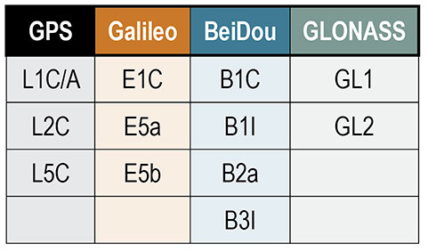
A total of 12 SDR codebases are aimed at processing each of the GNSS signals (see TABLE 1). All code files for each SDR are organized in the same subdirectories, and most of them have the same filenames.
Table 1. All GNSS signals that can be processed by the SDR collection, organized by their corresponding satellite systems.
All SDRs are set to work with a default configuration. They are all run using an init.m script, which collects user settings (input data file path, sampling frequency and so on) from the initSettings.m configuration script. Given this, the first file that users may want to modify is initSettings.m, to define the run settings for a given test. Most of the SDRs operate in an identical way, however some include particular features oriented at exploiting certain characteristics of the corresponding GNSS signal. The GPS L2C SDR, for example, gives the user the option of whether to process the pilot component of the signal.
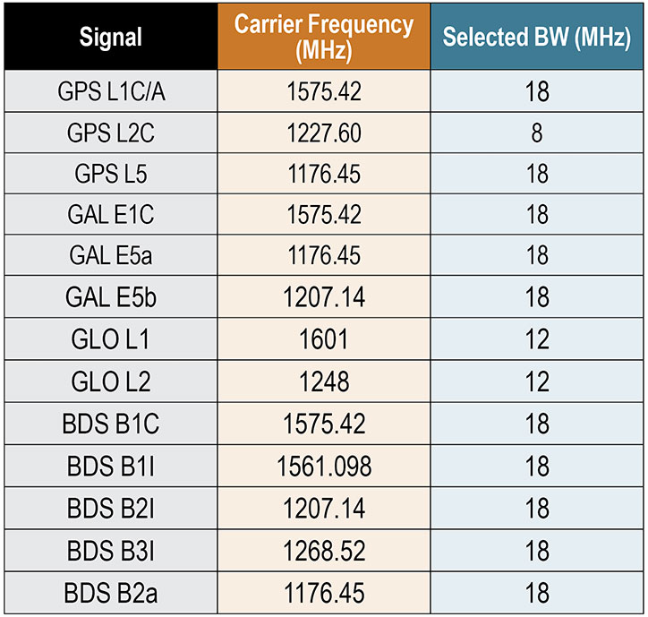
The test samples available in the public directory were obtained in accordance with the characteristics depicted in TABLE 2 for every signal. The first two columns from the left show all the signals the SDR collection can process and the central carrier frequency at which they are transmitted. The third column gives the bandwidth selected in the recording process for every signal. This value must match the sampling frequency defined in the initSettings.m file for each SDR. Only three frequency bandwidths can be used to record GNSS data, so as to make the configuration structure more homogeneous across different SDRs. They were selected to ensure similar characteristics for each signal in terms of performance, encompassing most of the signal power for each modulation, but also keeping the recorded GNSS data files within a reasonable size.
Table 2. Summary of the tested GNSS signals’ center frequencies and the selected bandwidth (BW) for their processing. The common IF for all signals is 20 MHz.
All the signals were mixed to a common intermediate frequency (IF) of 20 MHz in the recording process. Both the frequency bandwidth and the IF are fundamental to obtain the expected results from each SDR codebase. These are set in the settings file. The default configuration was validated in the testing campaign explained in later sections, and should only be modified to meet the user’s specific needs, being aware that some SDR performance characteristics may also be affected.
BASIC GNSS SDR STRUCTURE
While the general SDR receiver structure is similar across all codebases, each comes with adjustments and/or additions to adapt the code to the format of a specific signal. The general codebase structure can be summarized in four major modules:
signal acquisition
tracking stage
navigation data decoding
position, velocity and time (PVT) computation.
An important remark is that the SDR collection developed is designed to process files of limited duration. The code is designed to use enough data to provide a successful initial acquisition, and then use a single set of satellites for the remaining execution. In other words, there is no extra logic oriented at acquiring or reacquiring satellites after the first acquisition is achieved.
Signal Acquisition.The design of the acquisition scheme depends on the characteristics of the signal the SDR is aiming to process. There are numerous GNSS signal configurations for each constellation that follow different strategies concerning spreading codes, navigation data and secondary codes, which must be accounted for in the acquisition codebase.
All codebases follow a fast Fourier transform (FFT) accelerated serial search-acquisition approach to obtain estimates of the signal’s carrier frequency and code delay, where a number of signal replicas are generated iteratively, separated by a defined frequency interval in the frequency domain. All the frequency offsets are arranged in what are known as frequency bins. This frequency separation will be referred to as the frequency step. The latter is inversely proportional to the integration time and tells the maximum error allowed in the carrier frequency estimate, which is half the frequency step. Both the frequency step and the coherent integration time are parameters that have a strong effect in acquisition results, as will be seen below.
Each local replica is correlated with the input signal to obtain a code-phase estimate. The length of this correlation is the so-called coherent integration time. The maximum correlation measurement from all frequency bins is then divided by the second maximum found. This ratio is called the peak metric and is used in all SDRs to give a measure of the magnitude difference between the maximum obtained and the remaining correlation results. If the peak metric is not high enough, this implies that the maximum is close to other cross-correlation products and so could not correspond to the result obtained after correlating both input and local replica signals with the right code-phase alignment. When the peak metric surpasses the threshold defined in initSettings.m, the satellite is considered to be acquired.
It is worth noting that in all SDR implementations the local replica is constructed by concatenating a whole primary code and a block of zeros of the same length. This prevents navigation bit transitions from affecting the correlation results. For example, GPS L2C-CM SDR’s acquisition correlates 40 milliseconds of data with 20 milliseconds of pseudorandom noise (PRN) spreading code followed by 20 milliseconds of zeros (the zero padding technique).
Tracking Stage.The tracking stage is oriented at refining and keeping track of the code and carrier estimates provided by the acquisition stage as well as demodulating the navigation data. This is achieved using feedback loops organized in channels, which are typically referred to as tracking channels. There will be as many tracking channels as the number of satellites acquired. Each tracking channel makes adjustments to the corresponding local signal replica for the given satellite, so that it resembles the real received signal as much as possible. When the replica is sufficiently accurate, the tracking loop locks onto the signal, removes the carrier and spreading code components, and starts registering data bit transitions. The task of every tracking channel is to account for signal variations so that they can keep locked on the signal for as long as the satellite is available for use.
Tracking channels implement two feedback loops, the delay lock loop (DLL) and the Costas phase lock loop (PLL). The former is focused on the signals’ code phase while the latter on the carrier phase. These modules depend on two major parameters that determine the properties of the loop filter: the damping ratio and the noise bandwidth. On the one side, the damping ratio controls how fast the filter reaches the settling stage. On the other side, the noise bandwidth informs the amount of noise allowed in the filter.
While all SDRs follow similar tracking loop schemes, some signals, such as GPS L2C, need some adjustments to the parameters mentioned above so that they provide the expected results, as we point out later. Tracking results are stored in a Matlab .mat file, but also can be assessed in the plot the tracking stage generates after it finishes processing all the channels.
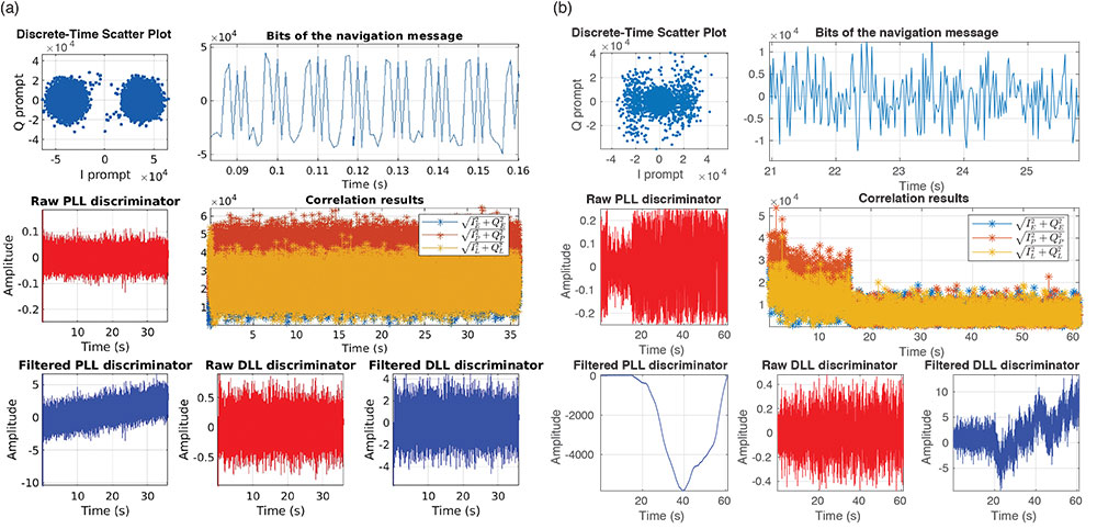
FIGURES 1a and 1b show an example of two different tracking results plots, each of which include seven figures. These show the in-phase/quadrature (I/Q prompts), the navigation data bits decoded, the changes in the raw/filtered Costas loop and DLL discriminators, and the early-prompt-late metrics. Note that the plots in Figure 1a suggest the navigation data bits were demodulated successfully. In contrast, in Figure 1b, data bits cannot be distinguished because the tracking stage failed to demodulate the navigation message.
Figure 1. (a) shows the plot generated for a successful tracking channel. In contrast, (b) illustrates the results obtained when the tracking loop in question did not lock appropriately to the signal and therefore was not able to demodulate navigation data. (Image: Authors)
Navigation Data Decoding.This stage extracts the navigation data required by the SDR codebase to compute PVT estimates from the results delivered by the tracking stage. The latter outputs I/Q prompt samples representing data bits, containing the encoded navigation data. The navigation data format for each signal can be found in the interface control document issued by each satellite constellation operator.
The general process that each SDR implements to demodulate navigation data from I/Q samples is summarized as follows:
detect a preamble within data bits
arrange the bit sequence in the corresponding structures, such as frames
remove secondary code if present
de-interleave and decode
check if the bit stream has errors
extract navigation parameters
Once navigation parameters are extracted, they are stored and later used by the functions involved in the PVT computation stage.
PVT Computation.The PVT stage takes the decoded navigation data, computes satellite positions, and solves the geometry problem, whose solution is the receiver’s location.
As with all the other stages, all SDRs follow the same approach, and use the least-squares method to solve for a position estimate once all the data is available. Position estimates are delivered in both Earth-centered Earth-fixed and east-north-up coordinates.
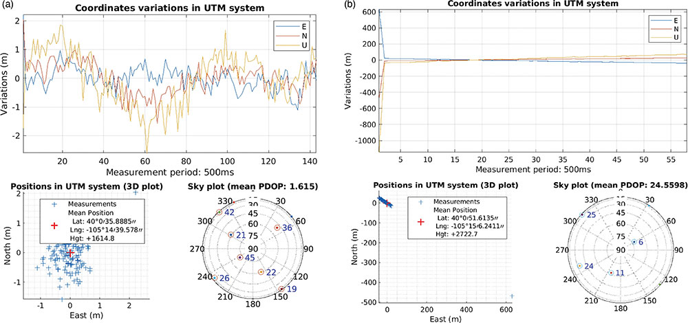
Similarly to the tracking stage, the PVT computation stage returns a plot showing some PVT statistics to help the user get an idea of the PVT performance of the test conducted. FIGURES 2aand 2b show an example of two positioning plots obtained for two different data files.
Figure 2. (a) shows the plot of a priori, good statistics for the navigation solution; (b) shows a navigation plot for a file that presented a problem affecting the PVT solution. (Image: Authors)
EXPERIMENTAL SET-UP AND TESTING
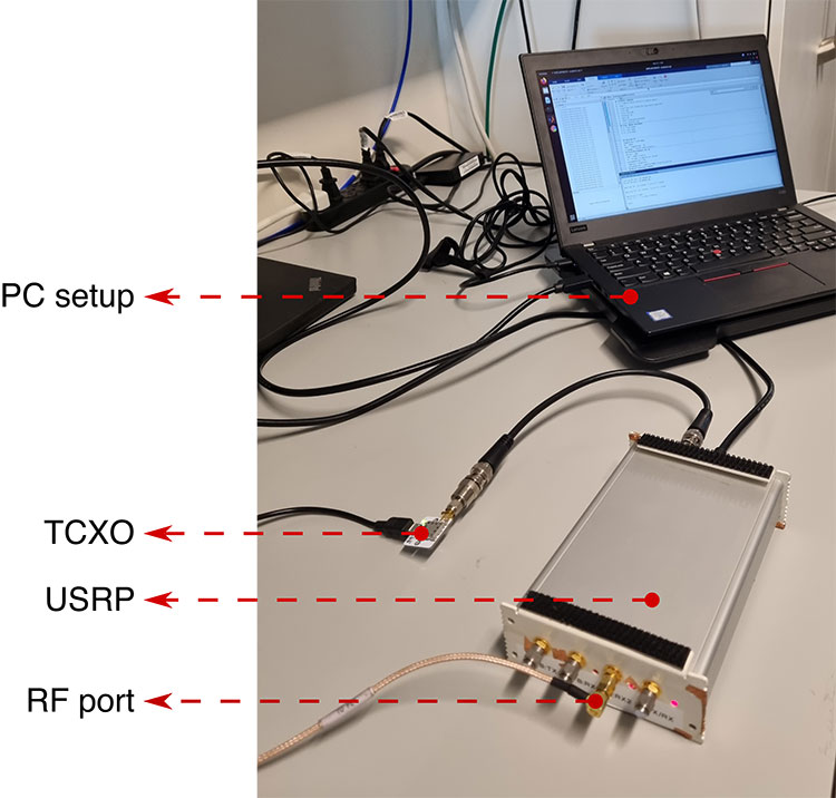
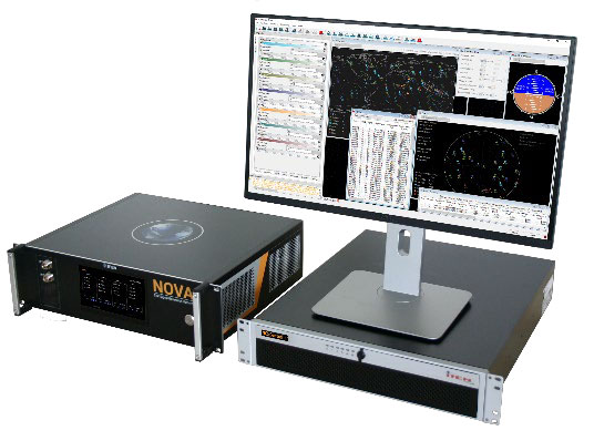
In this section, we present the equipment we used in our tests (see FIGURE 3) and detail the process we followed to collect GNSS data, as well as the testing framework designed to exercise the SDR collection.
Figure 3: The antenna was connected to the RF port of the USRP. The USRP sampled the analog data delivered by the antenna using the TCXO as the reference oscillator. The resulting sampled data was stored in a Linux-based computer. (Image: Authors)
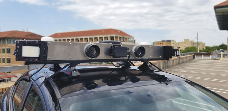
RF Antenna.The device used to sense the RF GNSS signals was a Trimble Zephyr2 antenna, which has enhanced capabilities for multipath minimization as well as low-elevation-angle satellite tracking properties.
The antenna was installed on the rooftop of the Ann and H.J. Smead Department of Aerospace Engineering Sciences building at the University of Colorado Boulder.
USRP and TCXO Devices.An Ettus Universal Software Radio Peripheral (USRP) B200 hardware SDR connected to an IQD temperature-compensated crystal oscillator (TCXO) was used to collect digital samples from GNSS analogue signals sensed by the antenna.
The B200 device was controlled by means of the USRP hardware driver (UHD) through a computer running a Linux operating system. UHD is a software application programming interface (API) that enables the development of code to manage USRP settings and operation.
PC Setup.The PC setup consisted of a Linux computerwith all the required drivers and program dependencies, as well as with Mathworks’ Matlab software installed. Matlab was used to program and automate the data recording process.
Recording Process.The equipment described in previous subsections was used to record data suitable for each SDR codebase. The process to obtain signal data for all 12 codebases was reduced to eight stages by selecting an adequate frequency bandwidth, as some signals share the same central carrier frequency (see Table 2).
For each stage, a total of 100 files with 61 seconds of I/Q GNSS data were recorded over a 24-hour time period. The I/Q samples recorded by the USRP were formatted as 8 bit sine carriers. All the data sets recorded are available together with a description file based on the Institute of Navigation’s metadata standard for GNSS.
TESTING FRAMEWORK
The workflow we followed to test every codebase from the collection is outlined in the following steps:
Record data samples.A set of one hundred files were recorded with 61 seconds of GNSS data.
Debug the SDR with the selected files. A debugging stage preceded every test case to ensure the codebase performed well enough, or else to make the required adjustments.
Run the SDR for one hundred trials. A total of one hundred tests, one per file, were performed for all SDRs.
Log metrics and present results.The results from all SDR stages (acquisition, tracking and data demodulation) were stored for each file. Also, each iteration returned a message that summarized the execution results.
All of the messages returned for every file corresponded to one of the cases summarized as follows:
Codebase issue. Message type returned when the codebase failed because of a coding issue.
No navigation solution. The codebase was not able to deliver a navigation solution either due to a malfunction of the codebase or due to a lack of satellite availability. Navigation solutions are only available when both the tracking channel and the navigation data demodulation stages are successful for more than three satellites.
Navigation solution with accuracy worse than 30 meters. A position solution fix more than 30 meters (in three dimensions) from the known antenna location was considered a non-accurate estimate.
Navigation solution with accuracy under 30 meters.When the 3D positioning error was < 30 meters, the navigation solution for the position was considered accurate.
All codebases passed a debugging stage before being tried with the whole set of available data. This was done to ensure that they performed as expected, and were able to achieve the required performance in terms of the metrics mentioned above in this section. An example of this debugging stage will be explained in further detail below. We take the GPS L2C codebase as an example of how all implementations were assessed in an attempt to improve their initial performance and make them more robust to code errors. See our proceedings paper for further details of our test cases.
GPS L2C Test Case.The problem observed for GPS L2C was that some satellites acquired with a high acquisition metric were failing the tracking stage. The result was that no navigation data was demodulated from them. An in-depth study was required to find out the adjustments needed in the codebase that would help to solve this issue.
The GPS L2C signal encompasses two signal components called civil moderate (CM) and civil long (CL). The CM component is formed by a spreading code that modulates a navigation message. The CL component is a pilot (data-less) signal modulated with a longer spreading code allowing for longer coherent and non-coherent integration times, yielding better sensitivity.
For CM signal acquisition, the 20 millisecond code length limits the coherent integration time to 20 milliseconds, due to the overlaid navigation message. This integration time defines the minimum frequency resolution required to obtain the expected correlation results. The CL component is used in the SDR to accumulate consecutive correlation results non-coherently, contributing to the receiver’s sensitivity by allowing it to operate with higher acquisition metrics in general.
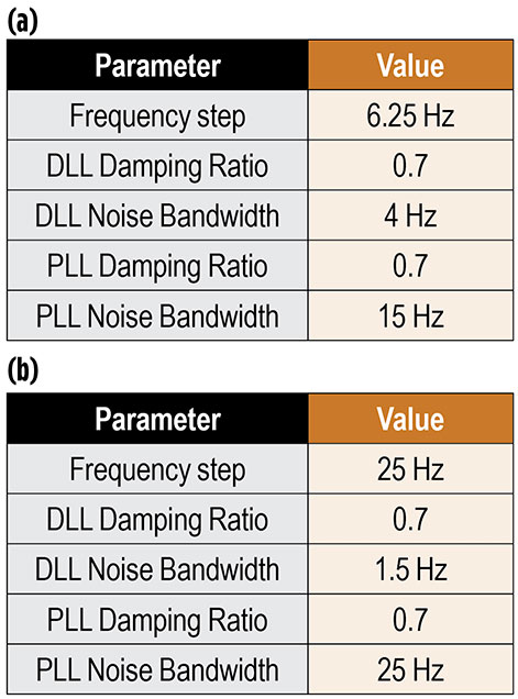
The initial configuration for this SDR codebase is represented in TABLE 3a.
Table 3. Configurations for GPS L2C test case.
With this configuration, a total of 10 satellites were acquired. However, it was observed that for some satellites acquired with high peak metrics, it was not possible to demodulate their navigation data, and thus they were not considered for the navigation solution in later stages. This situation was abnormal, as typically this behavior is more characteristic of weaker signals whose bit transitions are too noisy to be decoded. This problem suggested that either the code-phase or the carrier frequency estimates (or both) were not accurate enough for each tracking channel to generate a proper replica to lock onto the input signal.
The first step taken to address this matter was to inspect the SDR’s acquisition stage for a file presenting the mentioned problems. For instance, taking a closer look at the carrier and code-phase 3D representation for those satellites acquired with a high acquisition metric that were not successfully tracked afterwards. After doing so, some satellites were identified with the irregular characteristics described above, as for example the PRN 10 satellite. PRN 10 is taken as a reference throughout this subsection.
The metric analyzed for PRN 10 was the matrix built by the acquisition’s serial search process. This matrix contains the correlation results obtained for each frequency bin. The width of each frequency bin is determined by the frequency step size defined in the configuration file. In this way, the smaller the frequency step, the more frequency bins that the corresponding matrix contains. This implies a better frequency resolution.
With this in mind, the frequency resolution was progressively increased by decreasing the frequency step size. Extra logic had to be added to the acquisition algorithm to implement this feature. It was found that when using a step size of 6.5 Hz, the tracking stage was then able to lock and demodulate navigation bits from PRN 10 effectively. This was the most significant determining factor to overcome the issue in question for the majority of the satellites available. However, other smaller adjustments also improved tracking results in general. These are depicted in TABLE 3b.
CODE AVAILABILITY
All the resources concerning the SDR collection are publicly available at the portal hosted by University of Colorado Boulder. Through this portal, all the GNSS codebases along with the data sets for testing can be acquired, as well as access to the discussion forum.
CONCLUSION
The first version of the SDR collection was made available after the seminal text by Borre et al. was published and consisted of a GPS L1C/A SDR and multiple data sets. From then on, this project kept evolving by adding more SDRs as new GNSS signals emerged across different satellite constellations.
Our most recent work was to collect all the SDR codebases, arrange them in a common format, and test each implementation to assert their robustness and extract statistics concerning their performance.
Future work will be dedicated to adding more features aiming at refining the PVT estimates delivered by each SDR.
More progress is expected to be made soon, with additional improvements made in the GNSS laboratory. In addition, there is plenty of room for contributions from other researchers who want to support and collaborate with this open-source initiative. Our portal provides a convenient way to manage these contributions.
ACKNOWLEDGMENTS
We thank the many individuals who collaborated in the development of the open-source GNSS SDR collection.
This article is based on the paper “A Collection of SDRs for Global Navigation Satellite Systems (GNSS)” presented at ION ITM 2022, the 2022 International Technical Meeting of the Institute of Navigation, Jan. 25–27, 2022.
JOAN BERNABEU is a Ph.D. student at the Institut Supérieur de l’Aéronautique et de l’Espace, Toulouse, France. He also works as a satellite navigation engineer for GMV, Spain.
NICOLAS GAULT is a Ph.D student at École Nationale d’Aviation Civile, Toulouse, France. He was a visiting scholar in the Department of Aerospace Engineering Sciences at the University of Colorado (CU) Boulder in 2020-2021.
YAFENG LI is an associate professor in the School of Automation at the Beijing Information Science and Technology University, China. He was a visiting researcher with the Department of Aerospace Engineering Sciences, CU Boulder in 2017–18.
DENNIS M. AKOS is a faculty member in the Department of Aerospace Engineering Sciences at CU Boulder.
A roundup of recent products in the GNSS and inertial positioning industry from the November 2022 issue of GPS World magazine.
OEM
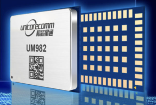
GNSS Module
For UAV, precision agriculture and autonomous machines
Photo: Unicore Communications
The UM982 GNSS module is a high-precision, dual-antenna real-time kinematic (RTK) positioning and heading module. It supports BeiDou B1I/B2I/B3I; GPS L1/L2/L5; GLONASS L1/L2; Galileo E1/E5a/E5b, QZSS L1/L2/L5; and SBAS in dual-antenna mode. The highly integrated, compact (16 mm × 21 mm × 2.6 mm) module can reduce the design area of an OEM board by 72% compared to previous modules. Power consumption is less than 0.6 W. The NebulasIV GNSS system-on-chip is a key part of the UM982’s navigation system. The NevulasIV integrates RF, baseband and high-precision algorithms on a single chip, with supporting functions built in. High-level performance indicators include raw observation accuracy, RTK positioning accuracy, precise point positioning accuracy, and time to first fix. The two antennas can independently participate in deriving an RTK solution and outputting the positioning results.
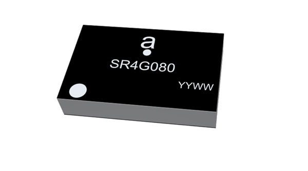
Alternative to ceramic patch provides omni-directional performance
Photo: Antenova
The Agosti (part number SR4G080) is a new miniature surface-mount-designed (SMD) antenna for GNSS applications. It measures 9.0 mm x 5.8 mm x 1.7 mm and operates with exceptional efficiency in a reduced space on a corner of a printed circuit board. It has a small ground-plane requirement of 40 mm x 20 mm, 70 mm x 25 mm and 80 mm x 30 mm, making it suitable for small form-factor designs such as wearable devices, trackers and onboard diagnostics.
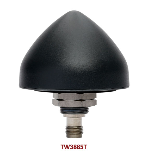
Housed Dual-Band antenna with Accutenna technology
Photo: Tallysman
The dual-band TW3885T antenna supports GPS/QZSS L1/L5; Galileo E1/ E5a/b; BeiDou B1/B2/B2a; GLONASS G1/G3; and satellite-based augmentation systems in the region of operation: WAAS (North America), EGNOS (Europe), MSAS (Japan) or GAGAN (India). It is housed in a through-hole mount, weatherproof (IP69K) enclosure. It mitigates the effects on GNSS receivers of new signals or harmonic frequencies from adjacent LTE bands on the radio-frequency spectrum. For permanent installations, L-bracket (PN 23-0040-0) or pipe (23-0065-0) mounts are available. Tallysman provides an antenna installation guide that recommends a 100 mm –125 mm ground plane and provides antenna installation and cable connector waterproofing best practices.
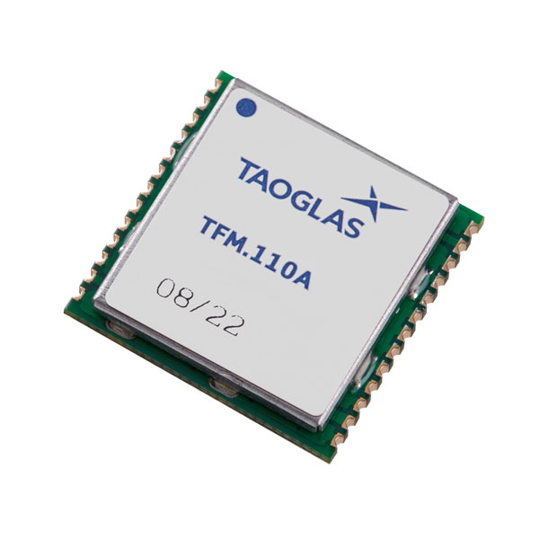
Simplifies product development for high-precision applications
Photo: Taoglas
The TFM.110A is the first in a new series of high-precision, multi-band GNSS front ends for autonomous vehicles, precision agriculture, automotive applications and robotics. It comes fully integrated with two cascaded low noise amplifiers (LNA) and pre-filters in a small, low-profile, shielded surface-mount package. When used between the device’s GNSS receiver and antenna, the two-stage amplifier solution eliminates the need for complex and challenging onboard filter and amplifier circuits. It supports L1, L2 and L5 bands and enables seamless signal transmission, signal purity and position accuracy in high-precision applications.
Provides interference, spoofing, encryption and authentication capability
Photo: IFEN GmbH
Version 2.8 of the NCS Nova RF signal simulator offers advanced capabilities. With integrated interference generation capability, the Nova can generate coherent interference signals with a signal power of up to –30 dBm. The ability to assign two users to one RF output enables integrated spoofing scenarios with a single RF output, meaning spoofing is available even with an entry-level single RF Nova. The new release has advanced navigation message authentication simulation capability compliant to User ICD 1.0 for the Galileo E1-B OSNMA, meaning specific OSNMA events can be simulated — key to ensuring compliant receiver behavior. Supported events include renewal and revocation of both a public key and a TESLA keychain. GPS cross-authentication and generation of Galileo E6-C encrypted codes are also supported.
Enables first responders to locate callers on floor levels
Photo: Polaris Wireless
Z-axis location service enables the pinpointing of a smartphone user within one floor level inside a multi-story building. The technology — demonstrated to meet the 3-meter vertical location accuracy requirement of the Federal Communications Commission (FCC) — is integrated into Schok Gear’s newly released flip phones. The Schok phones provide consumers with a simple, powerful device. Adding indoor and vertical location to these phones enables first responders to locate all wireless 911 callers with floor-level accuracy in multi-story buildings.
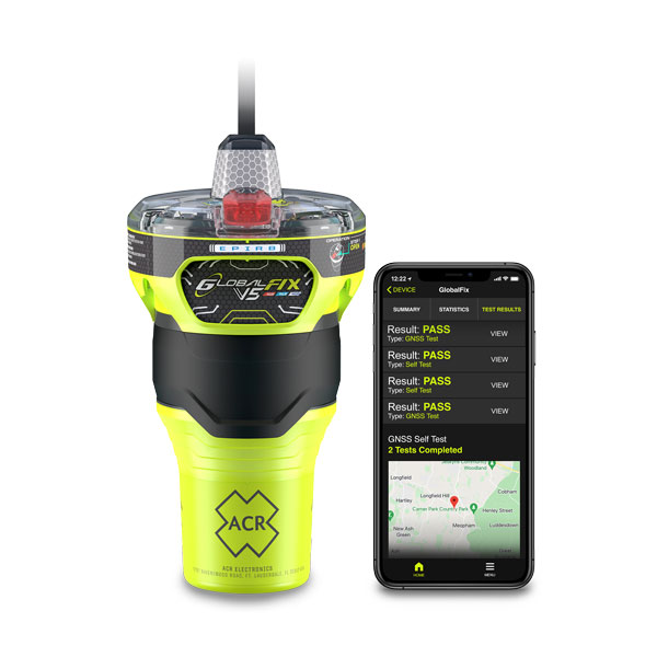
The new ACR Electronics GlobalFix V5 Emergency Position-Indicating Radio Beacon (EPIRB) and ResQLink AIS Personal Locator Beacon (PLB) have integrated the automatic identification system (AIS) to increase the speed of location and aid. They also are compatible with Return Link Service (RLS) alerting. The combination of services ensures faster rescue and increases chance of survival of both boat (EPIRB) and crew (PLB). The safety beacons deliver mobile connectivity to a cell phone with a free mobile app, made possible with the addition of near-field communication technology in the beacons. With the app, users can monitor their beacons, review self-test results, view GNSS test locations, and monitor beacon performance and maintenance by scanning the beacons with their mobile phones. Besides GNSS positioning, the lightweight beacons have 406-MHz Cospas-Sarsat distress signal with MEOSAR compatibility and 121.5-MHz local homing signal.
The Canvas Device Manager simplifies workflows for configuration and maintenance of internet of things (IoT) device deployments. It enables users to easily set up devices, monitor performance, and keep software up-to-date across the entire IoT device fleet. Device parameters can be remotely managed, and performance monitored. Canvas enables users to organize large numbers of devices to quickly build and maintain IoT solutions, and software updates can be remotely and rapidly deployed, thwarting security attacks.
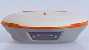
The N2 Palm RTK GNSS receiver is suitable for surveying, mapping and construction. It has a highly integrated main board and a three-in-one antenna, yet weighs 0.72 kg with battery and measures 48 mm. Powered by ComNav’s SinoGNSS K8 high-precision module, the N2 can track 1,590 channels, including all existing and planned signals of GPS, BDS-2, BDS-3, GLONASS, Galileo, QZSS and SBAS. Its advanced satellite-tracking technology ensures it works well even in harsh environments, such as under heavy foliage or close to buildings. A third-generation inertial measurement unit (IMU) makes the N2 immune to magnetic disturbance, which greatly improves its reliability. Pole-tilt compensation of up to 60° allows surveyors to locate points within 2.5 cm. By using the company’s Quantum algorithm, the N2 achieves calibration-free operation — after 10 seconds of initialization, users can make tilt measurements with centimeter-level accuracy for an extended period, greatly improving efficiency.
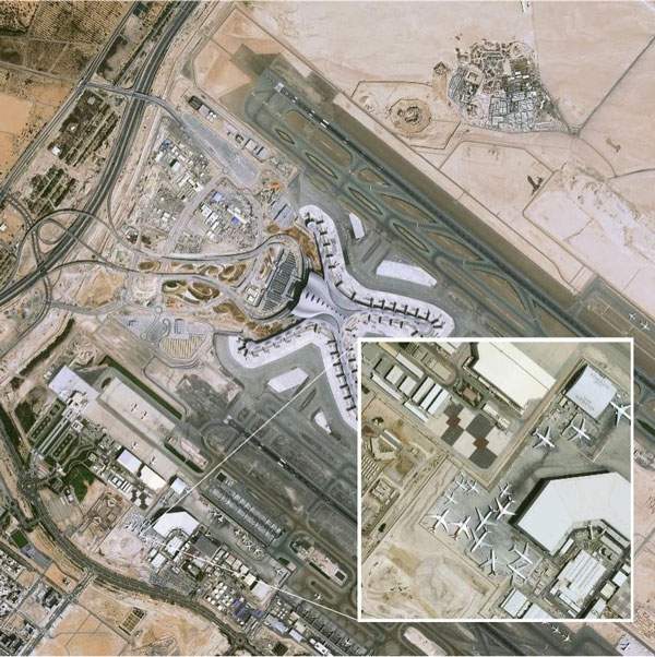
Airbus has added 30-cm Pléiades Neo imagery to its OneAtlas Living Library service. The new data source will complement the service which already allows users to instantly access a premium catalogue of Pléiades 50 cm and SPOT 1.5 m data via streaming, download and API. The Living Library provides frequent updates over urban areas, airports, harbors and military sites to name a few. Imagery is updated every day and processed in the cloud, with flexible options for integration into GIS workflows. With the OneAtlas Living Library, Airbus offers a pay-per-order option but also a subscription-based service that allows users to access premium content quickly available into their account, as well as a deeper archive of more than 10 years of imagery by Pléiades and SPOT satellites at a higher incidence angle and cloud coverage threshold, which will be available in just a few hours. OneAtlas also provides access to several other data services, such as reactive tasking, that allows users to task a full suite of optical and radar satellites, including Pléiades Neo, or access more than 15 years of global radar data, as well as the ability to download the WorldDEM product suite among others.
Free, user-friendly tool shows the Earth’s changes
Photo: Kermap
The Nimbo Maps platform provides monthly 10 m-resolution images of changes on Earth in a user-friendly format. The images are chronological, seamless and free of clouds, and include intuitive comparison timelapse features. The platform, developed by French startup Kermap, relies on innovative artificial intelligence methods to process satellite images supplied by the European Union’s Copernicus program through its Sentinel missions. APIs automatically retrieve data extracted from satellite imagery, providing Kermap customers with real-time, strategic, value-added information in the fields of agriculture, land planning and environmental transitions. Current coverage includes Europe, the Middle East and the United States, with plans to provide global coverage by early 2023.
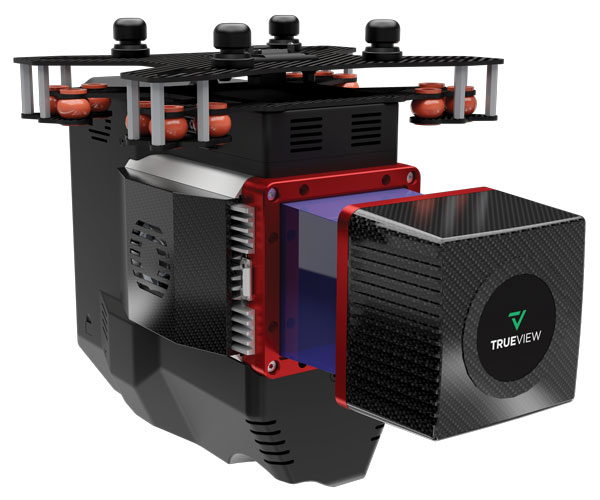
The TrueView 655/660 3D imaging system uses the Riegl miniVUX-3UAV laser scanner and three fully integrated mapping cameras (right, left and nadir) for high-accuracy mapping with excellent vegetation penetration and wire detection. Previous TrueView 3D systems carried dual oblique cameras to maximize mapping coverage. The TrueView 655/660 adds a third RGB camera, allowing for imagery directly below the sensor to be captured. The third camera provides a direct view of the ground below to maximize data collection for time flown, while improving the quality of photogrammetry and colorized point clouds.
Tbe company has received Global Certification Forum validation of 5G LBS Assisted-Galileo test case
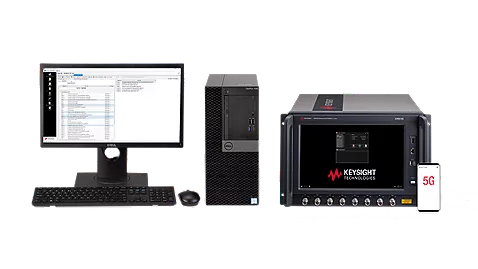
Keysight Technologies Inc. has gained Global Certification Forum (GCF) validation of a 5G location-based services (LBS) assisted-Galileo (A-Galileo) test case by combining 5G new radio (NR) and GNSS technology.
The achievement will accelerate implementation of LBS in smartphones by enabling mobile phone vendors to verify that designs comply to the latest 3GPP specifications that support accurate location positioning in a wide range of sectors.
Sectors include healthcare, road and aerial transportation, emergency and rescue services, public safety, and homeland security. Highly precise positioning services also enable mobile operators to deliver personalized services supporting entertainment, hospitality and retail applications.
LBS leverages different technologies, including GNSS, beamforming and round-trip time to geographically locate a user. LBS test cases allow users to verify sensitivity, accuracy and dynamic range in mobile phones that leverage GNSS constellations to identify precise geographic location.
S8705A RF/RRM DVT and Conformance Toolset. (Photo: Keysight)
GCF conformance agreement group meeting #72, held Oct. 21, confirmed the validation of the first 5G LBS A-Galileo test case, which was supported by Keysight’s S8705A RF/RRM DVT and Conformance Toolset. The toolset provides access to a wide range of radio frequency, radio resource management, and development validation test cases used to verify 5G NR designs in both non-standalone and standalone deployment modes.
The S8705A toolset uses the E7515B UXM 5G Wireless Test Platform, a compact signaling test platform with multi-format stack support, rich processing power and abundant RF resources for emulating various mobility scenarios in a 5G network as well as a recommended GNSS emulator to deliver the LBS test case.
Spirent Communications announced that the Spirent GSS7000 GNSS simulator has been integrated into Microwave Vision Group (MVG) over-the-air (OTA) and passive antenna test systems.
MVG, an antenna measurement solutions company, enables the characterization and evaluation of antennas for testing wireless connectivity, reliability, and standards compliance. MVG near-field test systems perform fast and accurate measurements for OTA tests of antennas designed for satellite communications and other GNSS-enabled products, systems, and networks.
As connectivity in industries such as automotive, aviation and military becomes ever more sophisticated, the need to ensure that all the pieces of technology work together in the way they should increases. The integration of Spirent into MVG test systems enables R&D engineers to incorporate the antenna and the vehicle in a test environment that represents the real-world signal environment as closely as possible while maintaining full control and repeatability.
“Our integration into MVG over-the-air test systems, such as the multi-probe SG24 or StarLab, delivers a cutting-edge testing solution, helping to accelerate the development of next-generation products and systems,” says Adam Price, VP of PNT Simulation at Spirent.
Global corporation VIAVI Solutions Inc. has completed the acquisition of Jackson Labs Technologies, a leader in positioning, navigation and timing (PNT) solutions for critical infrastructure serving both military and civilian applications.
Jackson Labs develops and supplies modules, subsystems and box-level solutions that include front-end receivers, transcoders, rack-mounted equipment, and patented retrofit technology. Their broad customer base includes armed forces, defense contractors, energy distribution infrastructure, low-Earth-orbit (LEO) operators and 5G service providers.
Jackson Labs’ next-generation M-code solutions complement and advance VIAVI’s timing and synchronization portfolio at a time when PNT requirements for defense, space, commercial aviation, transportation and telecommunication networks are expanding and becoming increasingly critical.
“As telecommunications, avionics and mission-critical infrastructure adopt next-generation technology, legacy timing and synchronization protocols are no longer sufficient. Jackson Labs is a trusted provider of PNT solutions in these markets, and we look forward to addressing these opportunities together,” said Oleg Khaykin, president and CEO of VIAVI. “With this acquisition, we are continuing to drive operational scale via the addition of advanced technology and high-performance products that address market segments with strong growth and profitability.”
“Being a part of VIAVI will significantly expand Jackson Labs Technologies’ market reach worldwide, and allow us to further deliver world-class solutions for the rapidly developing PNT landscape as it enters a new era,” said Said Jackson, CEO of Jackson Labs Technologies.
DelMorgan & Co. acted as the exclusive financial advisor to Jackson Labs in connection with the transaction. Terms of the transaction are not being disclosed.
About VIAVI
VIAVI s a global provider of network test, monitoring and assurance solutions for communications service providers, enterprises, network equipment manufacturers, original equipment manufacturers, government and avionics. It helps customers harness the power of instruments, automation, intelligence and virtualization.
VIAVI is also a leader in light management solutions for the anti-counterfeiting, consumer electronics, industrial, government and automotive markets.
VIAVI operates offices throughout North, Central and South America, Europe, Africa, the Middle East, and the Asia-Pacific, including China and Japan.
Averna and Physik Instrumente (PI) have formed a new partnership to deliver advanced automation solutions that meet the growing need for flexible, scalable and high-throughput manufacturing and test equipment.
Physik Instrumente (PI) is an international group of companies focusing on high-precision motion and positioning solutions, and Averna is a global test and quality solutions provider.
With significant overlap in several markets — industrial automation, automotive, consumer electronics, communications and life sciences — PI and Averna each offer expertise in different areas. Their goal is to expand each offering to their clients by integrating PI’s unique precision positioning and micro-robotics systems into Averna’s customized quality and assembly turnkey solutions.
To date, the two companies have delivered numerous joint projects, improving results for a variety of applications including camera and projector assembly, laser alignment, fiber alignment and optical wafer scanning.
“We are very excited to begin this partnership,” said Niels Davidts, vice president of Europe at Averna. “Having worked with PI products in the past, we understand the power of what they offer. They are unique in what they do, and we know how to make them work best for our clients. A closer partnership will open a lot of opportunities for both parties.”
Scott Jordan, long-standing photonics expert and business developer at PI emphasizes, “Working with Averna has been very rewarding. We have always been impressed with the systems they design for test, quality, and precision assembly. Combining our knowledge with Averna’s skills, we can now approach customer challenges in ways that have never been done before.”
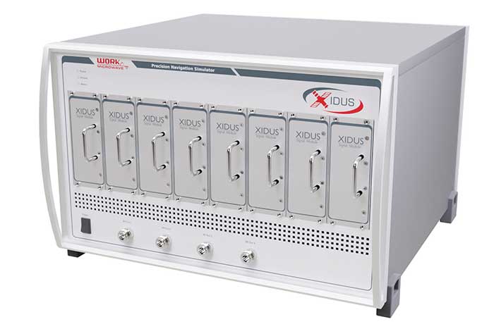
WORK Microwave demonstrated its Xidus GNSS Simulator at the ION GNSS+ 2022 conference, which took place last week in Denver.
The Xidus GNSS simulator provides high-fidelity, reliable RF signals with automated calibration, making it suitable for validating the performance of GNSS receivers for a wide range of applications, including spacecraft, aviation, unmanned aerial vehicles, digitalized agriculture, autonomous driving, and military drones and vehicles.
The Xidus GNSS simulator enables users to perform rigorous and extensive testing of GNSS systems. Through advanced customization and configurable capabilities, Xidus provides pure, perfectly synchronized and reliable benchmark signals distributed over one or many RF outputs. The wide, dynamic power range is a key differentiator, allowing users to perform real tests without attenuation artifacts. With the Xidus system, users can easily and effectively generate long-term, complex and reproducible yet variable scenarios at higher update rates without leaving the laboratory.
Xidus simulates multi-constellation, multi-frequency and multi-RF signals out of the box — for any position on Earth and in space. The simulator includes APIs and remote control for flexible system integration and automated testing. Modular signal-generation hardware allows simple plug-and-play module insertion, enabling easy and robust field upgrades whenever necessary, the company said.
WORK Microwave’s Xidus GNSS simulator series includes:
Xidus-Studio Software — This powerful and intuitive graphical user interface for the Xidus GNSS simulator simplifies the configuration of any scenario, providing access to a wide variety of parameters: different vehicle models with 6DOF, multiple vehicle simulation, spoofing and meaconing, multiple TX antenna patterns, multiple RX antenna patterns, industry standard error models, runtime distortions on individual channels, and more. Xidus-Studio also allows the design of bespoke satellite orbits ranging from LEO to GEO. The software runs on both Windows and Linux platforms.
Xidus-424 GNSS simulator — Offering a compact chassis with two RF outputs, it runs any scenario over multi-constellation/frequency even with the entry configuration. This chassis supports up to 128 LOS channels and 512 multipaths that can be seamlessly distributed over the two RF outputs.
Xidus-648 GNSS simulator — This is a bigger chassis designed to support the most demanding scenarios, up to 256 LOS channels and 1,024 multipaths, dispatched seamlessly over four RF outputs. The chassis can easily be cascaded if needed. The tool is suitable for test campaigns on receivers with multiple antennas.
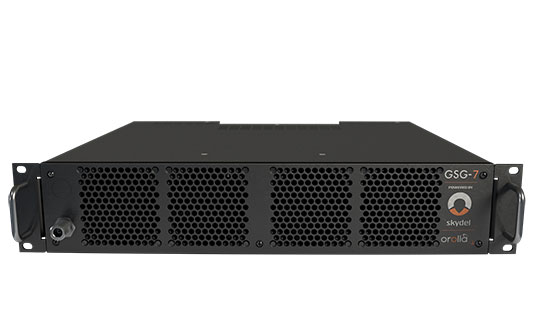
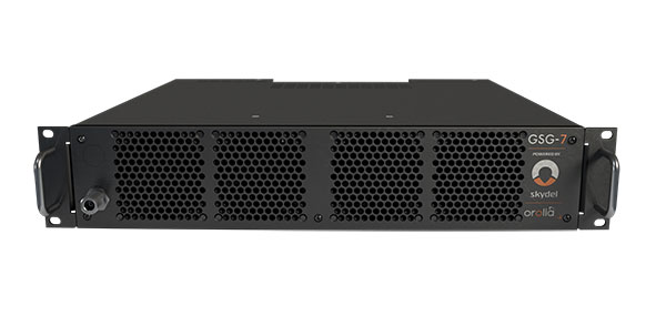
GSG-7 delivers the highest standard of GNSS signal testing in a cost-effective, easy-to-use, turnkey form factor supporting navigation and timing systems
Photo: Orolia
Orolia has released the GSG-7, its latest GNSS signal testing solution.
Orolia made the announcement at the ION GNSS+ conference, taking place this week in Denver.
Offered through the Orolia family of Skydel-based simulators, the GSG-7 features a small form factor, an internal RF combiner, high-end performance with a 1,000-Hz simulation iteration rate, real-time synchronization, hardware-in-the-loop (HIL) integration, powerful automation, and multi-constellation and multi-frequency simulations.
“The GSG-7 is redefining the essential and high capabilities in GNSS simulation with its ease of use, advanced simulation capabilities, reduced size, and competitive price,” said Lisa Perdue, simulation product line director. “Leveraging the powerful Skydel software and commercial-off-the-shelf (COTS) hardware, GSG-7 can accommodate almost any configuration to conduct system testing and simulation. The use of SDRs [software-defined receivers] means that maintenance and customization are not only easier, but more cost-effective than other options on the market.”
Powered by Orolia’s Skydel simulation engine, the GSG-7 can be programmed to simulate operations with all current GNSS signals, as well as future ones. Skydel’s architecture makes the GSG-7 future-proof by allowing new, incoming signals and updates to be implemented through software updates.
The GSG-7 simulator is suitable for development and integration projects that require high performance, all-in-view satellite signals, and an increased number of GNSS constellations.
“Capable of handling complex simulation scenarios, the GSG-7 has a simple, yet powerful application program interface (API) ensuring easy automation and integration into your test environment,” Perdue added. “Users can also benefit from advanced HIL capabilities that include zero-effective latency and built-in performance monitoring tools.”
GSG-7 Webinar
Orolia will host a product webinar on Oct. 6 to discuss the new GSG-7 in great detail. Topics will include: