Asynchronous GBPS can improves both convergence speed and positioning reliability
Precise point positioning (PPP), a high-accuracy GNSS technique, offers the advantage of centimeter-level positioning without relying on local reference stations. However, PPP often requires many minutes to achieve full precision, making it less suitable for dynamic environments.
Previous efforts have shown that ground-based positioning systems (GBPS) can accelerate convergence by providing additional geometric constraints. Yet most GBPS solutions depend on highly accurate time synchronization among base stations, which increases infrastructure costs and limits deployment flexibility.
Asynchronous GBPS (A-GBPS) remove this synchronization burden, but their potential for augmenting PPP has remained largely unexplored. Deeper investigation into practical PPP augmentation with A-GBPS is needed.
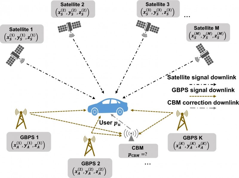
Researchers from the Department of Electronic Engineering at Tsinghua University report a new GNSS augmentation framework in a study published (DOI: 10.1186/s43020-026-00200-4) in the journal Satellite Navigation. The researchers developed a tightly coupled positioning architecture that integrates GNSS with A-GBPS. By combining satellite and A-GBPS observations, the framework significantly accelerates positioning convergence and improves solution stability, offering a practical pathway toward more efficient high-precision navigation services.
Rather than requiring all base stations to share the same clock, the new framework embraces their asynchronous nature. The researchers developed a method that uses a dedicated monitoring station to correct transmitter clock biases before integrating the measurements with GNSS observations. This allows the system to exploit the strong signal power and favorable geometry of ground-based transmitters without the operational burden of network-wide synchronization.
The team first established a theoretical model showing that adding A-GBPS observations should reduce positioning uncertainty. Numerical simulations then demonstrated that adding A-GBPS can significantly strengthen geometric constraints, particularly in the directions where satellite-only positioning is weak. The benefits became even more pronounced after the positioning solution stabilized, suggesting that A-GBPS can complement GNSS throughout the positioning process.
Field test results
To test the approach under real-world conditions, the researchers deployed six A-GBPS base stations and conducted field experiments using a mobile receiver platform. Compared with GNSS-only positioning, the augmented system reached higher accuracy with faster convergence and delivered more stable positioning performance.
The experiments also revealed an important engineering insight: adding more base stations generally improved performance, but the gains began to level off beyond about five or six stations. This finding may help future network designers balance positioning performance against deployment costs.
The authors said the work demonstrates that high-precision PPP augmentation does not necessarily require tightly synchronized GBPS. Instead, asynchronous GBPS can provide valuable geometric information that improves both convergence speed and positioning reliability.
Using existing 5G networks
They said the results indicate that existing terrestrial communication facilities, like 5G, could potentially support future positioning services. Such an approach may offer a practical pathway toward more accessible high-precision navigation without high deployment expense and complexity, which usually associated with synchronized GBPS.
The implications extend beyond navigation research. Faster and more reliable positioning could benefit autonomous driving systems, unmanned aerial vehicles, intelligent transportation networks, surveying operations, and mobile mapping platforms that depend on rapid access to precise location information. Because the framework is compatible with existing radio infrastructure, it may lower barriers to deployment and expand positioning coverage in challenging environments.
The researchers note that future work will focus on eliminating the need for a dedicated monitoring station and evaluating performance under more complex urban conditions, where signal blockage and multipath interference are more prominent.
The forum brings together experts from industry and regulatory authorities to discuss the future of network and spectrum monitoring in increasingly complex RF environments.
The forum will provide a full day of insights, technical exchange, and hands-on demonstrations. Rohde & Schwarz and its partners will present keynote addresses and expert presentations, and provide networking opportunities with professionals from across the network and spectrum monitoring ecosystem. Participants also can consult directly with Rohde & Schwarz technology specialists.
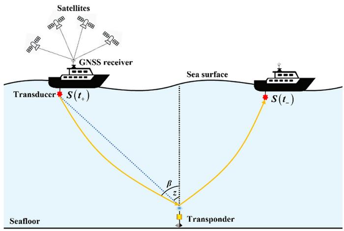
Incorporating a layered horizontal gradient structure can improve GNSS-Acoustic (GNSS-A) seafloor positioning, according to a new research paper in the April 20 issue of Satellite Navigation.
GNSS-A integrates satellite positioning of a sea-surface platform with underwater acoustic ranging to achieve seafloor positioning accuracy at centimeter level. This technique supports the construction of seafloor geodetic observation networks, improves the oceanic component of the International Terrestrial Reference Frame (ITRF), and provides a key means for monitoring tectonic deformation and related submarine geohazards.
However, the accuracy of GNSS-A seafloor positioning is affected by spatiotemporal variability in the ocean sound speed field. The conventional depth-invariant horizontal sound speed gradient models represent the water-column sound speed structure using a single effective depth-averaged gradient, which cannot adequately describe the vertical heterogeneity of horizontal gradients and therefore introduce model errors and positioning biases.
To address this issue, the authors propose a layered sound-speed gradient model and a corresponding joint inversion framework for precise GNSS-A seafloor positioning.
The proposed method parameterizes horizontal sound-speed gradients in multiple depth layers and couples adjacent layers through depth-weighted interlayer continuity constraints, which jointly estimates seafloor transponder coordinates, the depth-invariant temporal perturbation, and layer-wise horizontal gradients.
Results of simulations
Simulation results under depth-dependent horizontal gradient scenarios show that the conventional single-layer model introduces systematic positioning biases, whereas the proposed layered model significantly improves positioning accuracy, accurately estimates the temporal perturbation and layer-wise horizontal gradients, and is robust for a broad range of layering configurations and constraint parameters.
Field experiments using real GNSS-A observations further demonstrate the practical value of the proposed method, with results showing that the proposed approach improves the fitting of acoustic observations, maintains short-term repeatability, and yields consistent multi-epoch coordinate time series together with reasonable site-velocity estimates.
These findings indicate that incorporating a layered horizontal gradient structure can improve GNSS-A seafloor positioning and provides an interpretable modeling and inversion framework for long-term seafloor deformation monitoring and characterization of ocean environmental variability.
“Precise acoustic seafloor positioning with joint estimation of sound speed field structure using a layered sound speed gradient model,” by Yang, W., Xu, T., Wang, J. et al, can be downloaded from Springer’s website.
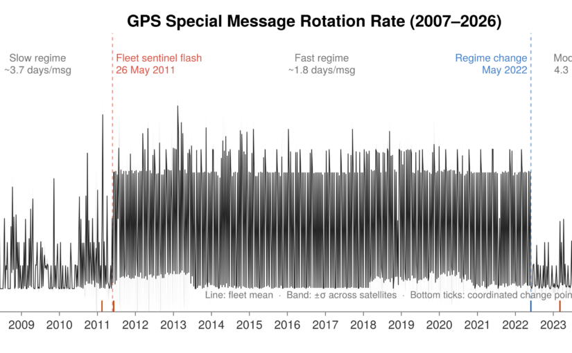
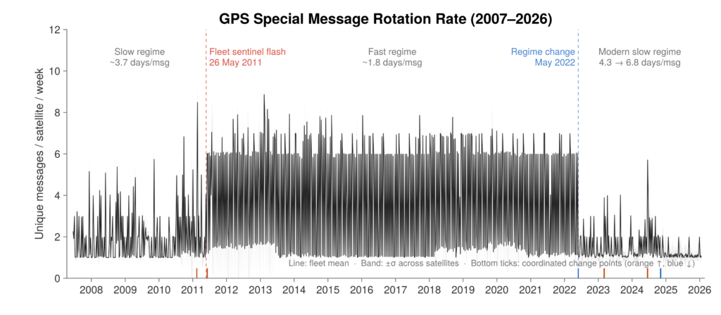
The Information Security researchers at University College London (UCL) analyzed an archive of 12.16 million GPS observations collected between 2007 and early 2026 to understand what the broadcasts actually contain.
To make processing this massive dataset practical, the researchers built a Julia pipeline to extract the bits directly into a DuckDB database. This setup allowed them to run queries across 19 years of global ground-station data in milliseconds.
Read the full analysis in the researchers’ blog here.
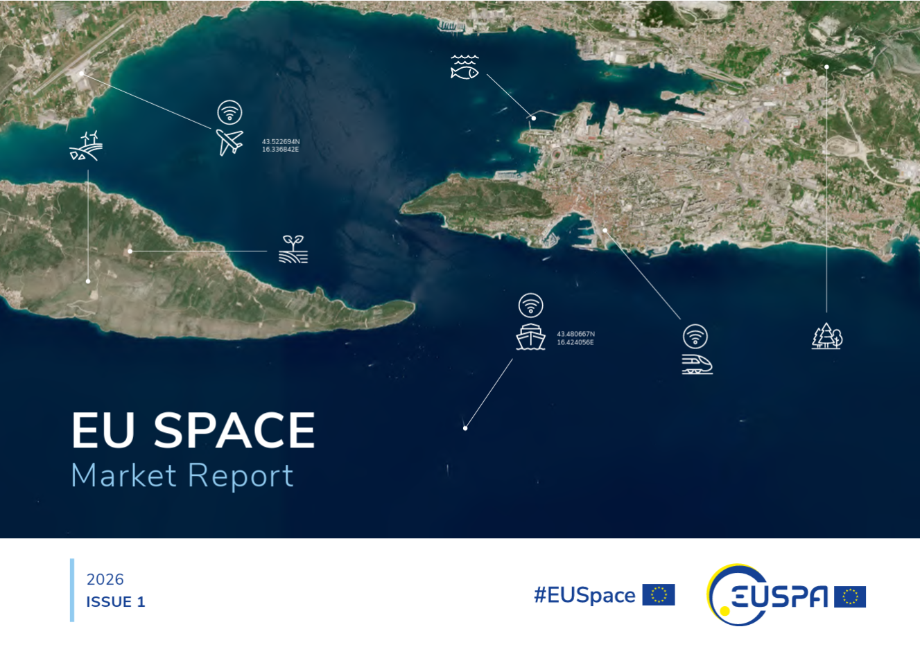
A new edition of the European Union’s Space Market Report is now available. According to the EU’s Agency for the Space Programme (EUSPA), it offers a comprehensive overview of the latest developments, emerging trends, and market dynamics shaping the global space downstream sector.
The report provides a comprehensive overview of the latest developments and trends in GNSS, as well as Earth observation (EO), secure satellite communications (Secure SATCOM), and space situational awareness (SSA) in one place for the first time. It also highlights the evolution of user technologies and the growing synergies between these domains.
“As Europe’s space capabilities become increasingly interconnected, it is essential to move beyond viewing them as standalone technologies,” explained Rodrigo da Costa, EUSPA executive director. The publication “reflects the growing synergies between these domains and their strategic importance for Europe’s economy, resilience and autonomy.
“By providing a comprehensive view of the evolving space ecosystem, EUSPA aims to foster innovation, strengthen collaboration across the sector, and support the development of a more competitive, agile and responsive European Union space economy,” da Costa said.
GNSS and EO
The report highlights sustained growth for both the GNSS and EO markets across all 16 analyzed market segments. The current €3.5 billion of EO market revenue in 2024 is expected to grow to €7.9 billion by 2034 with agriculture representing the largest share.
GNSS revenues are forecast to rise from €300 billion in 2024 to €580 billion by 2034. GNSS service revenues outpace device revenues and confirm the increasing role of digital ecosystems and value-added services in the space economy, the report said.
Revenues are mainly driven by consumer solutions, and road and automotive, with a global installed base of GNSS-enabled devices that will reach almost 10 billion by 2034.
Secure SATCOM
The Secure SATCOM market addresses the needs of surveillance, key infrastructure and crisis management. In this sector, data service revenues generated by EU users are forecast to grow significantly, increasing from more than €200 million in 2025 to nearly €1.2 billion by 2040.
While maritime surveillance drives demand in 2025, by 2040 the market is expected to be led by law enforcement interventions, civil protection and force deployment, fueled by growing security and resilience needs, demand for reliable connectivity, and stronger crisis-response capabilities.
Existing and future synergies
The report also examines how major macroeconomic trends —including climate change, geopolitical instability and rapid urbanization — are reshaping space markets and strengthening synergies between EO, GNSS and Secure SATCOM technologies. Together, these capabilities are becoming increasingly important for security, resilience, disaster response, environmental monitoring, and smarter urban and infrastructure management.
A joint measurement trial, Rohde & Schwarz and Greenerwave have demonstrated that a near-field system can record a full radiation pattern of a 50 cm Ku band electronically steerable array for a SATCOM antenna in a half hour.
The achieved results match simulation models within a decibel, making this approach a fast and reliable way to verify antenna performance.
For manufacturers of SATCOM systems facing large chamber constraints, it offers a clear path to quicker, more cost-effective testing.
Electronically steerable array (ESA) antennas are becoming key components in modern SATCOM systems. Accurate knowledge of their radiation pattern is required for reliable operation in LEO, MEO and GEO orbits. However, conventional far‑field testing demands chambers that are often larger than practical for Ku or Ka band antennas, especially when the aperture of the Antenna Under Test (AUT) reaches half a meter or more.
Compact Antenna Test Ranges (CATR), on the other hand, are still relatively large for these AUTs and require time-consuming dual-axis positioning of AUT to map the radiation pattern.
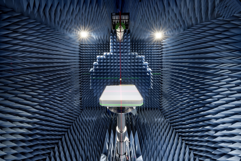
Rohde & Schwarz and Greenerwave have reached a breakthrough in ESA antenna testing in a joint measurement trial, achieving highly accurate radiation pattern characterization in the near field, significantly reducing measurement time. Greenerwave’s innovative SATCOM user terminals are based on reconfigurable intelligent surfaces (RIS), allowing the company to design electronically steerable antennas that deliver high-performance connectivity while reducing energy consumption and reliance on semiconductors compared with conventional solutions.
For the joint measurement campaign, Rohde & Schwarz provided its R&S TS8991 over‑the‑air and antenna measurement system, equipped with a conical cut positioner, and its R&S ZNA vector network analyzer. Together, they evaluated Greenerwave’s passive single‑aperture ESA that uses RIS technology for beamforming. The antenna under test (AUT) features a 50 x 50 cm aperture and is designed for low power consumption and easy integration.
The measurement covered an extended upper hemisphere down to a polar angle of 120 degrees, using a one-degree step size. Ten Ku band frequencies were recorded in a total of 32 minutes, thanks to the system’s hardware trigger function. Data was processed using the R&S AMS32 antenna measurement software, which applied a FIAFTA near-field-to-far-field transformation algorithm.
Comparison with the original simulation based on a numerical twin model and with results from Greenerwave’s CATR setup showed peak gain or directivity variations of max. 1 dB and typically 0.3 dB, validating the accuracy of the near-field solution. Export options allow users to continue analysis in tools such as CST Microwave Studio or MATLAB.
The trial shows that even large SATCOM antennas can be characterized quickly and accurately with the R&S TS8991 antenna test system from Rohde & Schwarz in a near-field setup, providing a practical alternative to large-sized far-field chambers or CATRs.
According to Rohde & Schwarz, the system setup can be used by other SATCOM makers testing broadband, IoT or back haul antennas for applications requiring flexible beam control and high data rates. The setup can be integrated more easily into research lab environments, and it shortens test cycles, reducing overall development cost.
Cost-effective sensors from the University of Bonn are measuring water levels along rivers and coastlines in Africa and the Pacific region.
Using a low-cost sensor and GNSS Interferometric Reflectometry (GNSS-IR), river water levels can be monitored around the clock. The water-level data are automatically transmitted via cellular networks to an analysis center.
Researchers at the University of Bonn developed the method several years ago and tested it on the Lower Rhine. With support from the European Space Agency (ESA), the monitoring system is now also being used in Africa and the Asia-Pacific region.
Researchers at the Institute of Geodesy and Geoinformation at the University of Bonn, led by Makan Karegar, have transferred water -level monitoring technology from the Rhine to Africa, Australia and the Philippines as part of ESA projects. Originally developed in the DFG Collaborative Research Center SFB 1502 (DETECT), the technology enables continuous, freely accessible monitoring of inland and coastal waters in data-poor regions worldwide.
Active on three continents
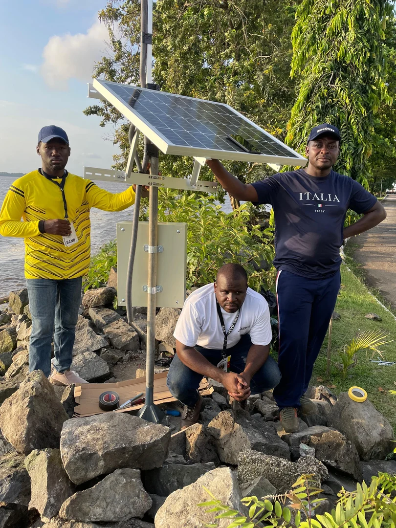
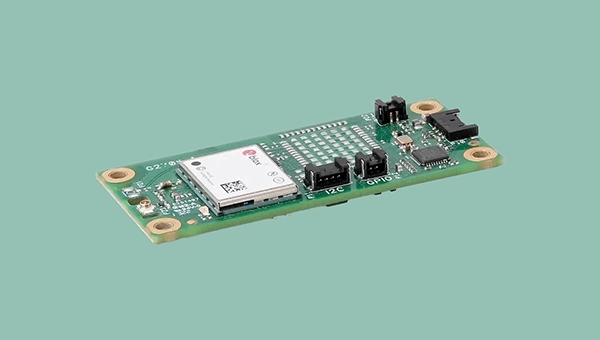
The technological centerpiece is the Raspberry Pi Reflector (RPR), a compact, solar-powered sensor developed at the University of Bonn. Using GNSS-IR, it measures water levels with centimeter-level accuracy.
Only a portion of the signals emitted by the GNSS satellites is directly captured by the antenna. The rest is reflected by the water surface and reaches the receiver via this detour. When superimposed with the directly received signal, it forms specific patterns known as interference patterns. These can be used to calculate the distance from the antenna to the water surface.
Each unit costs less than 800 euros, is powered by solar energy, and transmits data daily via mobile networks. “Modern gauge stations are prohibitively expensive, and conventional ones are highly vulnerable to flood damage,” said Makan Karegar, project manager. “These two factors together have left many countries in the global south with little to no ground-based water-level monitoring. The low-cost GNSS-IR sensor was developed precisely to address this gap.”
CAMEO-WAGST Project
The CAMEO-WAGST project (“Cameroon Advanced Measurements for Enhanced Observations of Water levels using Affordable GNSS-IR and Sentinel-3 & 6 Technology”) has established the first dedicated GNSS-IR network for monitoring water levels along coasts and rivers in Camroon and was funded by ESA. Between May and June 2025, researchers collaborated with Loudi Yap, director of the Research Laboratory in Geodesy at the National Institute of Cartography to install eight RPR sensors in Cameroon: two on the Sanaga River and six along the coast. “A lack of infrastructure for reliable hydrological and coastal monitoring in Cameroon has so far hindered effective flood risk management and early warning systems,” Yap said.
This collaboration, under the umbrella of the EO Africa Research and Development Facility, is already bearing fruit, said Roelof Rietbroek, research coordinator at ESA’s EO Africa R&D Facility. “We hope this paves the way for more reliable monitoring of flood-prone regions in Africa.”
St3TART-FO Project
Building on this success, the follow-up project St3TART-FO also was launched in collaboration with ESA. A total of 17 RPR sensors will be installed in seven countries, including West Africa, Australia and the Philippines. “The goal is to create a freely accessible reference measurement network for calibrating satellite data,” Karegar said. For the first time, the network will provide continuous water-level data at previously unmonitored locations.
The collaboration is based on years of scientific exchange between Africa and Europe. Partners include:
International Institute for Water and Environmental Engineering (2iE), Burkina Faso
National Institute of Cartography, Cameroon
Environmental Protection Authority (EPA), Ghana
Nigeria Hydrological Services Agency (NiHSA)
University of Maiduguri, Nigeria
Assane Seck University of Ziguinchor, Senegal
University of Southern Queensland, Australia
University of the Philippines Diliman.
Technology Transfer and Capacity Building
Both projects promote technology transfer and local capacity building through training, workshops and mentoring, enabling partner institutions to operate RPR networks independently. “We want to leave behind a sustainable monitoring capacity that is operated by local scientists and institutions, openly shared with the world, and maintained well into the future,” Karegar said.
With financial support from the Transdisciplinary Research Area (TRA) “Sustainable Futures” at the University of Bonn, Karegar developed the open-access data platform gnss4surfacewater.com, which provides an independent, ground-based service for monitoring current and historical water levels using GNSS-IR. Also visit CAMEO-WAGST GitHub for code and field photos.
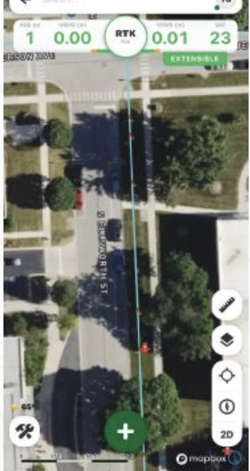
FastXY can transform standard mobile devices into professional-grade data collection tools for geospatial information systems (GIS) and architecture, engineering and construction (AEC) professionals. FastXY offers professionals the ability to collect point, line and polygon data, and delivers advanced capabilities including 3D basemaps, construction staking, topographic surveying, on-the-fly datum transformations and survey-grade elevations. A built-in Bluetooth data parser allows users to configure the app to collect data from virtually any instrument supporting BLE Bluetooth or RS-232 — including echosounders, radiation sensors, laser rangefinders, barcode scanners and more — and marry that data instantly with precise GNSS coordinates. Available in free and premium versions.
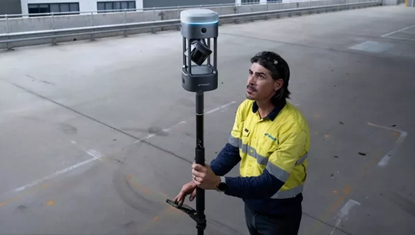
Handheld scanner: Designed for BIM, indoor scanning and reality capture
The RS7 handheld SLAM (simultaneous localization and mapping) scanning solution was built for BIM documentation, indoor surveying, renovation planning and complex spatial analysis. It is designed to help professionals capture high-density 3D data efficiently and convert it into practical deliverables through CHCNAV’s software and cloud ecosystem. The RS7 integrates a next-generation lidar scanner capable of measuring up to 1.15 million points per second. Its wide field of view (360° x 189°) supports comprehensive coverage of floors, walls and ceilings, helping reduce the need for repeated passes and complex capture maneuvers in tight or cluttered spaces. The scanner also includes a high-precision inertial measurement unit with bias stability better than 0.5°/h. By combining lidar and inertial data, the system is designed to maintain stable motion estimation and consistent point-cloud quality in environments that challenge many mobile workflows, including long corridors, repetitive structures, and feature-limited interiors.
Mobile scanner: All-in-one system offers SLAM, LIDAR, RTK and 360 degree imagery
The GX1 is an integrated, highly accurate all-in-one mobile scanning system combining simultaneous localization and mapping (SLAM), lidar, real-time kinematic (RTK) georeferencing, cameras and software. It supports a seamless workflow, from capture to deliverable, and can reduce the time required to survey a site by up to 95%. The independently validated global accuracy of 5 mm to 10 mm delivers the precision needed for topographic and road surveying, scan to building information models, construction progress tracking, and more. These capabilities are supported by integrated RTK georeferencing with real-time quality monitoring, four 20MP cameras for 360° panoramic imagery, and a proven SLAM algorithm. The GX1 has four deployment modes — backpack, survey pole, vehicle mount and supported handheld.
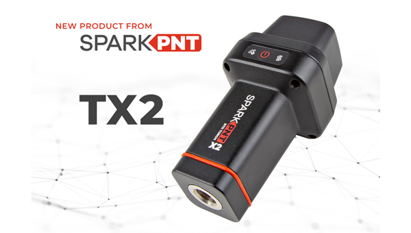
Quad-band GNSS rover: With support for Galileo high accuracy service
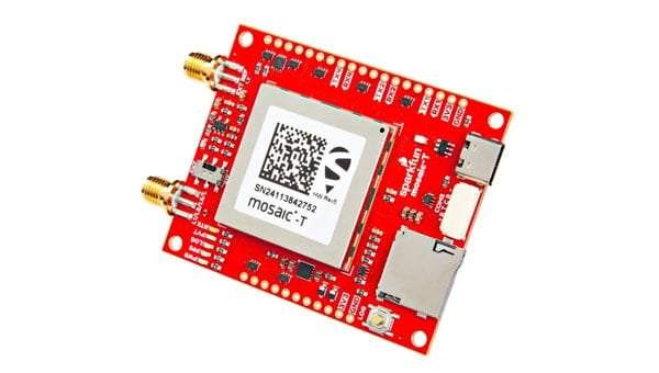
The SparkPNT TX2 quad-band GNSS rover combines an IP67-rated aluminum enclosure with support for Galileo’s High Accuracy Service (HAS) and standard RTK correction workflows. The receiver is built around the Quectel LG290P quad-band GNSS engine and supports multi-constellation tracking. Galileo HAS support provides sub-20 cm accuracy globally without subscription-based correction services, while RTK workflows via NTRIP or u-blox PointPerfect can achieve centimeter-level positioning. Battery life is rated at 50-plus hours, positioning the TX2 for multi-day field campaigns without recharging. The unit connects to iOS and Android devices via Bluetooth and WiFi, with compatibility reported for common GIS and data-collection applications. A notable design choice is the open-source firmware, which gives users visibility into how positioning data is processed and allows for customization and third-party integration. SparkFun has positioned this as an alternative to closed GNSS ecosystems where firmware and processing pipelines are not user-accessible.
Mobile
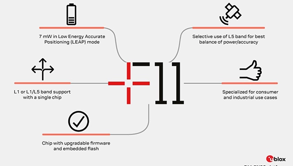
GNSS platform: Provides ultra-low power GNSS for all environments
The u-blox F11 platform provides L1/L5 dual-band standardprecision GNSS to improve positioning accuracy while reducing power consumption to as low as 7 mW in typical configurations. It combines ultra-low power operation with intelligent signal management to meet the evolving demands of tracking, wearables, telematics and mobility applications — including micromobility solutions and drones. The platform enables device manufacturers to achieve longer battery life, faster and more reliable position fixes, and greater design flexibility. Its situationally aware GNSS architecture, with integrated geofencing and indoor detections, dynamically balance accuracy and power consumption. By selectively using dual band L1/L5 operation only when it helps maintain positioning performance, the platform reduces energy use while providing resilience and maintaining confidence in location data.
The Iridium 9604 is a compact, threein-one internet of things (IoT) module that integrates Iridium short burst data satellite service, LTE-M cellular connectivity, and GNSS positioning into a single platform. The Iridium 9604 seeks to make dual-mode IoT connectivity viable for price-sensitive, high-volume deployments. Built on the u blox SARA-R5 platform, the module comes in a compact 16 mm x 26 mm x 2.4 mm form factor, suitable for dual-mode IoT deployments across industrial, infrastructure and mobility applications.
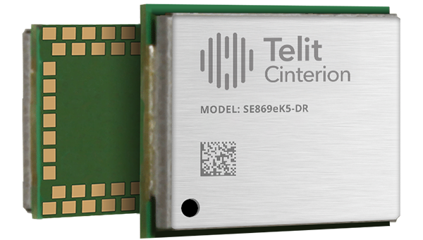
L1+L5 GNSS modules: For trackers and high-precision IOT
Two dual-band positioning modules built on Airoha’s AG3335 chipset series are available: the ultracompact SE873K5-D and the high-end SE869eK5-DRK. Both support space- and power-constrained IOT devices and use cases that require continuous, ultraprecise positioning. The modules provide a scalable path to adopt dual-band L1 + L5 GNSS.
Timing
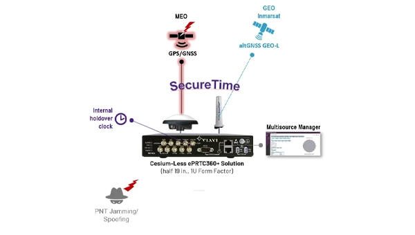
Cesium-less clock: An alternative to cesium-accuracy holdover clocks
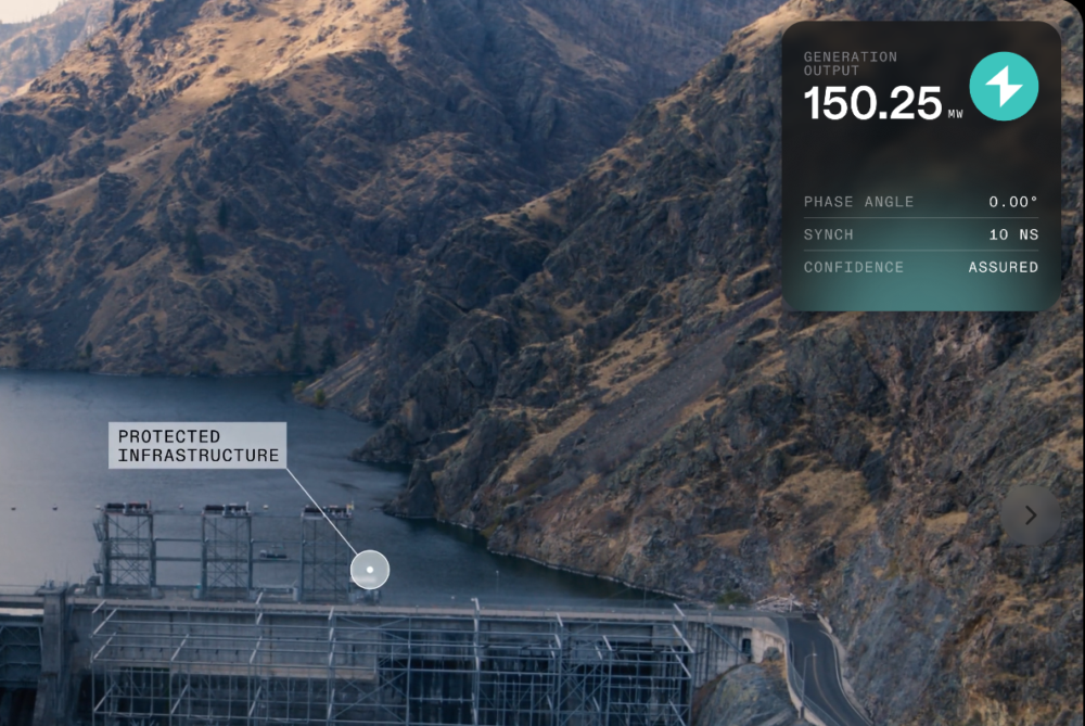
The patent-pending Cesium-less ePRTC360+ holdover solution is designed to safeguard atrisk infrastructure against the increased threat of GNSS timing disruptions. It is the only alternative to Cesium clocks to meet ITU-T G.8272.1 standards. It can protect critical power grids; transportation, aviation and public safety systems; 5G mobile networks; and AI data centers. It meets the international ITU-T G.8272.1 standard and has been successfully tested across a range of livesky defense and commercial jamming/spoofing environments. It has been integrated into VIAVI’s SecurePNT 6200 product series and can maintain 100 ns accuracy during GNSS-denied threats through the resilient altGNSS GEO-L service with no time limit.
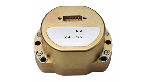
The U4930 series is a reliable and cost-effective six-axis microelectromechanical system (MEMS) and inertial measurement unit (IMU) module for navigation, control and measurement of vehicles, ships and drones. Applications include vehicle/ship attitude measurement, UAV attitude reference and trajectory control, mobile mapping, track inspection and underwater highprecision navigation. The U4930 series integrates high-performance MEMS gyroscopes and accelerometers within an independent structure. The three-axis MEMS gyroscopes sense the angular motion of the carrier, and the three-axis MEMS accelerometers sense the linear acceleration of the carrier. The system internally performs compensation for zero bias, scale factor, non-orthogonal error and acceleration-related terms across all temperature parameters, maintaining high measurement accuracy over a long period of time. The module supports custom communication protocols and provides synchronization for GPS/GNSS time data and pulse per second (PPS) signals.
Underground navigation: For navigating mines and unmapped environments
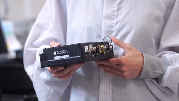
Chimera Land is a 3D laser velocity sensor (LVS) designed to solve the primary challenge for underground mining: maintaining precise vehicle positioning in deep, dark and unmapped environments where GPS cannot reach. When fused with an Advanced Navigation inertial navigation system (INS), Chimera Land allows underground vehicles to maintain stable navigation over extended distances and time. Instead of needing to query an external beacon or satellite for its location, the sensor uses specialized lasers to measure a vehicle’s ground-relative 3D velocity with high accuracy. By feeding this precise data into the vehicle’s INS, the sensor eliminates the drift that typically comes with standalone INS. Using AdNav Intelligence, the result is a resilient, high-performance, infrastructure-light positioning solution that excels in the highdust, zero-light conditions typical of underground mines.
Simulators
GNSS test tool: Provides real-world testing with signals from the field
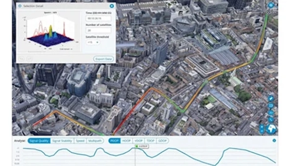
The SimXTRACT GNSS test tool bridges the gap between field and laboratory. It enables signals captured in field environments to be comprehensively decomposed into individual, discrete signals and applied to lab simulation for realism at every stage of the development test cycle. Developers usually rely on either RF record-and-playback or lab simulation for testing and validation of PNT systems and devices. SimXTRACT takes real signals captured in field environments and performs complex signal decomposition, breaking down each received signal into discrete line-of-sight and multipath ray paths, along with metadata such as Doppler offset, code error, power level and angle of arrival. This decomposed environment is then automatically converted into fully controllable simulation scenarios for Spirent GNSS simulators.
Autonomous
Inertial measurement unit: For unmanned air, land and sea
Honeywell launched the HGuide i700, an inertial measurement unit (IMU) that delivers high-accuracy performance for unmanned air, land and sea vehicles. By pairing near navigation-grade capability with a nolicense-required (NLR) classification, the HGuide i700 provides integrators worldwide with a new option for critical sensing and navigation. The HGuide i700 uses high reliability sensors and electronic architecture found in Honeywell’s HG3900 inertial measurement unit (IMU). Compact and low power, the HGuide i700 delivers near-navigationgrade accuracy and reliability while being optimized to support longer range navigation in GNSS-denied environments. The HGuide i700 offers strong GNSS-denied performance for by limiting maximum acceleration and spin rates in a license-free package. The latest in Honeywell’s HGuide suite of no-license inertial solutions, the HGuide i700 allows customers to streamline development cycles, simplify system architecture and transition to field deployment quickly. The HGuide i700’s rugged design, compact size and low-power profile make it suitable for diverse commercial, industrial and defense applications, including autonomous vehicles, mapping and surveying.
Anti-jam antenna system: Provides multi-constellation, multi-frequency GNSS signal protection
The GAJT-AE3 protects all major GNSS constellations from jamming with full multiconstellation, multi-frequency coverage, ensuring reliable PNT in demanding airborne environments. Its antenna electronics mitigate interference by creating up to seven nulls per band in the direction of jammers, providing significant anti-jam protection even in dynamic multi-jammer scenarios. The output is a protected radio frequency signal, free from jamming and suitable for input to modern and legacy GNSS receivers. The GAJT-AE3 protects and supports all GNSS frequencies, including L-band corrections and Iridium PNT.
OEM
GNSS board: All-band multifrequency reception and HAS-ready
Syslogic’s new all-band GNSS expansion board for rugged embedded computers is powered by the u-blox X20 receiver. It supports all major GNSS constellations and frequencies, including L1, L2, L5, L6 and L-band, and enables the use of the Galileo High Accuracy Service (HAS). It provides centimeter-level positioning, opening up new applications across industries such as autonomous field management, operation of construction machinery in remote areas, or navigation of automated guided vehicles and autonomous mobile robots. The GNSS board is designed for worldwide use. The integrated u-blox receiver supports modern correction techniques such as RTK, PPP-RTK and PPP. For the first time, it has been fully optimized for PointPerfect Global, u-blox’s proprietary high-precision GNSS correction service, delivering centimeter-level positioning anywhere in the world. This is particularly useful in remote areas without cellular coverage.
GNSS L1/L5 breakout: For meter-level positioning in embedded applications
The SparkFun GNSS L1/L5 Breakout – NEO-F10N (SMA) is a compact GNSS module designed for meter-level positioning accuracy in embedded applications. It uses dual-frequency L1 and L5 bands, with the L5 signal offering improved performance in urban environments due to reduced RF interference within the protected ARNS spectrum.
The board supports concurrent reception of GPS, Galileo and BeiDou, and uses u blox dual-band multipath mitigation to enhance accuracy in challenging conditions. It features a single UART interface, with an onboard CH340 USB-to-serial converter for easy connection to a computer, and standard pin headers for integration with external systems.
The module includes an SMA connector for secure antenna attachment and is configurable using u-blox u-center software.
The 23rd International Flight Inspection Symposium (IFIS) will gather experts in San Salvador May 4-8. There, Rohde & Schwarz will demonstrate its test and measurement solutions for ground-based navigation aids. The exhibits address the rising traffic volumes and stricter safety requirements.
Rohde & Schwarz will take part in the conference’s technical sessions with a presentation on “Challenges for UAV Operations in RF Dense Aerodrome Environments.”
The aviation sector today faces increasing air traffic density, rapid technological advancements and heightened security concerns, the company explained. Operators need test equipment that delivers laboratory level precision while tolerating the harsh environment of an airport runway or a remote navigation site.
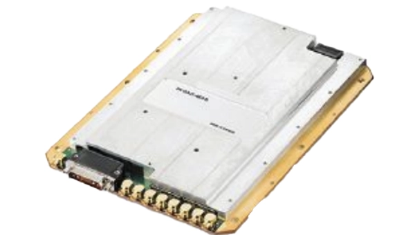
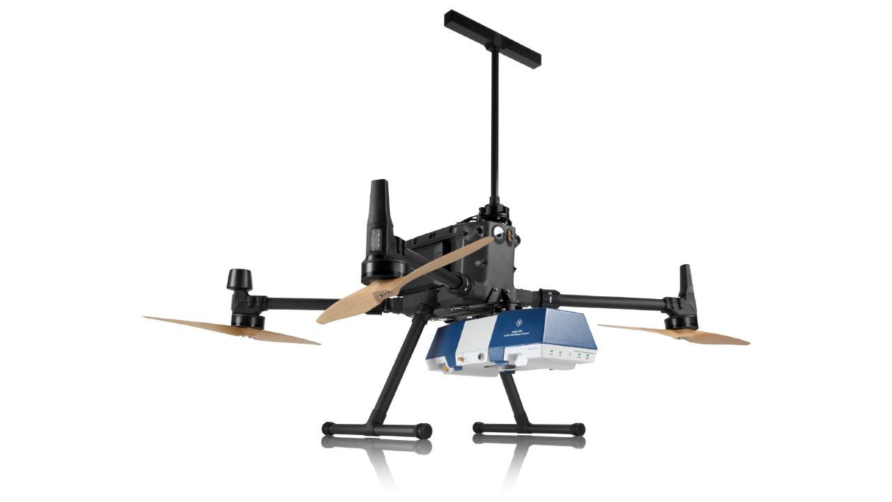
Among the exhibits at the Rohde & Schwarz booth is the R&S EVSD1000 VHF/UHF Nav/Drone Analyzer, designed to conduct GBAS, ILS and VOR measurements in line with ICAO Doc 8071 and ICAO Annex 10. The receiver delivers laboratory precision, supports an air to ground Wi‑Fi datalink and gapless measurements with improved location accuracy during flight inspections. Customers benefit from a device that can be mounted on a drone, reducing the need for manned flights and lowering operational expenses.
Rohde & Schwarz gives airlines, airport operators and navigation service providers a reliable way to certify and maintain ground‑based aids under today’s demanding conditions. By combining high measurement accuracy, easy operation and durability, Rohde & Schwarz aims to help the industry keep pace with growth.
A ceiling fan slowly churned, stirring the hot, humid air. Outside, warm rains pelted the muddy streets as distant langurs whooped in the thick jungle mists below.
An incessant fly caught the attention of the office’s lone occupant, hunched over a table covered with a large grid-lined sheet of paper. Pencils, erasers, French curves and straightedges lay scattered next to a stack of calculation sheets, but the man holding a pencil in one hand gripped a rolled newspaper in the other, intent on his battle with the fly.
Suddenly, the door burst open.
“Mr. Waugh!” the intruder exclaimed, panting as he rushed in.
“Radhanath,” Waugh replied in surprise, looking up from his maps. “I thought you were in Calcutta, 1,600 km away.”
“Yes, Mr. Waugh, I was, but this is too important to deliver by post.”
“Really, Radhanath. You intrigue me,” replied Waugh. “Come out with it. Your excitement is adding to this already unbearable heat.”
“Sir,” Radhanath tried to say calmly. “I have discovered the highest mountain in the world!”
That conversation happened in 1852. It was the crown jewel of an effort that began 50 years earlier. Britain was on the ascent. Surveying was the mathematics of empire. India, Britain’s largest protectorate, had never been systematically mapped. The British East India Company needed to know what minerals, crops and commodities could be turned into profitable enterprises, where they were, and how to move them to ports. This depended on accurately mapping India. Infantry officer William Lambton proposed an audacious solution: measure the entire subcontinent with triangles.
William Lambton
Lambton was granted the commission, and on April 10, 1802, the Great Trigonometrical Survey (GTS) of India began with a humble but critical baseline from St. Thomas Mount near Madras, 12 km south to Perumbauk Hill. Everything depended on the accuracy of this first baseline: even the smallest error would multiply as triangles spread across the subcontinent. Perfection was essential. The distance was measured with a 100-ft steel chain protected from the sun beneath A-frame tents to prevent thermal expansion. It moved slowly, 100 ft at a time from start to finish. Every link mattered. The baseline took 57 days.
To guarantee perfect alignment, Lambton relied on a massive custom-built theodolite. It weighed 1,102 lbs, requiring 12 men to carry. Surveyors planted stakes, stretched strings, and used the theodolite to correct for every change in elevation, turning a simple chain measurement into the geodetic foundation of the entire survey.
Time marched on faster than the survey. The East India Company estimated five years, but by 1818, the survey reached west to Mangalore and north to Hinganghat. It was too slow. Lambton’s vision of “an uninterrupted series of triangles…from sea to sea…to an unlimited extent in every other direction,” a complete geometric quilt covering India, proved implausible. Malaria took its toll. Lambton’s health declined and in 1823 he died at Hinganghat. George Everest inherited the survey.
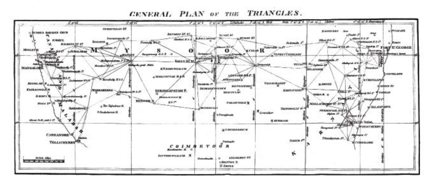
The map of triangles covered Madras to Mangalore.George Everest
Everest recognized Lambton’s dream of total coverage would take centuries. Instead, he conceived a “gridiron” of chains running north–south and east–west, intersecting at right angles, scaffolding to which localized surveys could be tied. The shift is evident on the GTS map: dense triangulation in south-central India reflects Lambton’s ambition, while the more open, structural network elsewhere reveals Everest’s pragmatism.
By the 1830s, Everest’s survey party had grown into slow-moving caravans, reaching as many as 1,000 people at peak times. Contemporary accounts describe columns supported by elephants, horses and camels, with hundreds of porters carrying tents, instruments and provisions. The logistics were immense: scouts rode ahead to negotiate passage with villages, reapers with scythes gathered grass for the animals, hunters supplied fresh meat and a traveling treasury paid workers and suppliers. To villagers, an approaching column appeared like a military invasion. Negotiations for assistance and safe passage could halt the survey for days.
The survey’s path was relentless. The Great Arc bisected India along the 78th meridian, from Cape Comorin to Bangalore, across the Deccan Plateau, through Hyderabad, over the northern plains to Dehra Dun at the Himalayan foothills. They didn’t simply pass through. They stayed. Sometimes for weeks, building 50 ft masonry towers to mount the theodolites.
When daytime heat and haze made measurements impossible, Everest shifted to night surveying using powerful lanterns visible from 30 miles away. They constantly adapted due to temperature, atmospheric refraction, verification baselines measured at the chain ends. Every measurement propagated from that first line at Madras; a minor error would compound over thousands of miles.
The price was paid in lives. Malaria wiped out entire parties. Three officers died in the Terai, the malarial lowlands of northern India. Two more retired, health-shattered. Everest himself contracted malaria repeatedly, suffering partial paralysis. The climate, he wrote, was “very deadly.”
Andrew Waugh
The survey transformed the land. To achieve clear sight lines, villages were razed, sacred hills appropriated, and community supplies exhausted. Yet the work continued. In December 1841, almost 40 years since the GTS began, the 1,500-mile Great Arc was complete. The spine was in place. Everest retired in 1843, passing the work to Andrew Scott Waugh, who extended the gridiron eastward. Nepal and Tibet were closed to outsiders. Waugh understood the distant Himalayan peaks, more than a hundred miles away, would have to be measured from the border stations anchored to the GTS framework. Accuracy became even more critical. This shift in focus from Everest’s large sprawling triangles inching north like a spider’s web forming the Great Arc, to Waugh’s tight triangles hugging the Himalayan frontier is visible on the GTS map.
Over the next decade, Waugh’s teams pushed eastward through the jungles of Bengal, Bihar and Orissa, verifying baselines, fixing latitudes and longitudes astronomically, establishing stations that brought the peaks within mathematical reach. Along the entire border, surveyors recorded the peaks.
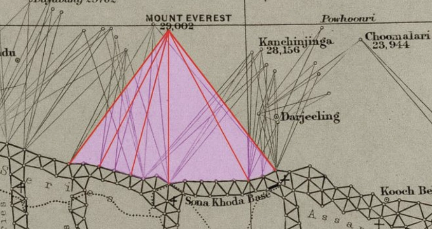
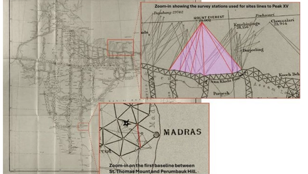
Close-up of the border survey stations used to observe Peak XV. (Credit: Royal Geographical Society)
To measure Peak XV, six observation stations were selected across the Terai, the deadly malarial lowlands chosen for the clear site lines to the summit. From these stations, surveyors recorded azimuth and elevation angles across multiple seasons. They measured the summit at sunrise, when the peak was first illuminated. None of the surveyors knew the height of the mountains they were observing because distance could not be measured directly. Only when all stations were plotted on a map could the peak’s position be fixed and the elevation calculated. This high-level mathematics fell to the human computers in Calcutta, led by Radhanath Sikdar.
Radhanath Sikdar
By 1851, Sikdar had risen to chief computer, directing the department that transformed field observations into verified measurements. The 1851 Survey Manual acknowledged his distinction: “Babu Radhanath Sickdar, the distinguished head of the Computing Department…whose intimate acquaintance with the rigorous forms and mode of procedure…render his aid particularly valuable.” Yet, neither his education nor his geodetic calculation training prepared him for the complexities of the Himalaya problem. Nonetheless, he took the raw observations and calculated the mountains’ heights to determine which, if any, of the distant peaks was truly the highest point on Earth.
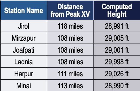
Sikdar calculated the height of each of the peaks. There were many. It was slow, meticulous work. Peak XV required more than standard calculation. Six observation stations produced six independent height measurements, each requiring corrections for atmospheric refraction (light bending through air layers of varying density and temperature), Earth’s curvature (the summit was more than 100 miles away), and plumb-line deviation (the Himalayas’ mass pulled survey instruments slightly toward the mountains).
Sikdar applied the Method of Least Squares, a statistical technique for extracting the most probable value from multiple observations. Each station’s measurement carried uncertainty; combining all six through rigorous mathematics yielded a more reliable result.
The calculation took months. When Sikdar finished, he was stunned: exactly 29,000 ft recalculated and received the same result. The precision seemed too perfect. Sikdar knew the stakes. This wasn’t just another mountain. His calculations were correct. Peak XV was the highest point in the world, Chomolungma, meaning the goddess mother of the Earth. Such a discovery demanded the honor of delivering the news in person.
In April 1852, Sikdar traveled 1,600 km from Calcutta to Dehra Dun. The journey took weeks. He carried the calculations in his satchel and the announcement in his mind.
When Sikdar burst into Waugh’s office with the news, Waugh worried that exactly 29,000 ft (8,830 m) would make surveyors appear to have simply rounded. 2 ft were added, a small fiction to preserve credibility. The official height for Peak XV became 29,002 ft.
Waugh spent four years verifying before the official announcement in March 1856. The mathematics were sound from the moment Sikdar burst into that office. Then, 20 years later, the 1875 Survey Manual erased Sikdar’s name entirely. The British press called it “robbery of the dead.”
Sikdar’s calculations have stood the test of time. The 1954 Survey of India measurement, 102 years later, yielded 29,028 ft, a minimal difference. In 1999, GPS technology placed a receiver on Everest’s summit for the first time: 29,035 ft. The 2015 earthquake prompted the most comprehensive measurement yet.
On May 22, 2019, at 3 a.m., Nepali surveyor Khimlal Gautam departed Everest’s South Col for the 10-hour climb carrying 90 lbs (41kg) of equipment. The pre-dawn timing avoided crowds: the weight included a Trimble R10 GNSS receiver and ground-penetrating radar to distinguish rock height from snow depth. Eight continuously operating reference stations (CORS) were positioned across Nepal to receive signals from GPS, GLONASS, Galileo and BeiDou. Chinese surveyors simultaneously measured from the north.
Gautam spent hours on the summit, collecting data while his body slowly consumed itself in the death zone. He lost a toe to frostbite. A team member nearly died from oxygen depletion. Gautam understood, “Mount Everest symbolizes something in Nepal, but it’s not only a Nepal asset, it’s a world asset.”
The map of the Great Trigonometrical Survey. (Credit: Survey of India, via David Rumsey Collection)
On Dec. 8, 2020, Nepal and China jointly announced their result, agreeing for the first time the height was 29,031.69 ft. Sikdar’s error across 168 years was 31.69 ft, an accuracy of 0.11%.
From that moment in Dehra Dun, Sikdar, dusty from the road, calculations in hand, certainty in his voice, we trace backward through 50 years of framework building to understand what made that measurement possible. Peak XV, hidden in plain view, seen for hundreds of miles, refusing to be known, was finally measured.
Once we have measured it, we want to believe we know it, but the Indian and Eurasian tectonic plates continue to collide, pushing the mountain up four millimeters per year. Earthquakes in the region change the topography. The geoid problem persists: What does “sea level” mean 440 miles from the coast in a gravitationally dense region? Modern surveyors still grapple with the fundamental question: What does “height” mean when measured against a theoretical reference surface?
The Great Trigonometric Survey proved that surveyors could measure what they couldn’t touch, calculate what they couldn’t reach, and verify what they couldn’t see. It required building the geodetic infrastructure across a subcontinent, maintaining mathematical precision across decades, and accepting brutal human costs.
Then, the computer was a man. The information was in his satchel. The message was delivered in person. It was the first time the height of the highest known point was determined not by a physical barometer on a summit, but by mathematics alone, a man solving equations in a room 440 miles away. Sikdar proved the impossible: What couldn’t be touched could be measured, what couldn’t be reached could be calculated, and a man dusty from the road could hold the height of the world in the palm of his hand.
Four names for one mountain. Each represents a different understanding. Its ancient name, Chomolungma, and Sagarmatha, its national identity. Peak XV, its cartographic name marking the audacious attempt to measure it, and the name Mount Everest, the crowning achievement, a proclamation honoring mathematics, from Hipparchus who is credited with developing trigonometry to the computers, like Sikdar. It stands as a monument to all the surveying and cartography, especially of the 19th century accomplishing the impossible against extraordinary odds.
Surveying and mapping are jobs of courage and determination exploring the unknown, risking death in malaria-infested jungles, Everest working while stricken with partial paralysis, Abdul Hamid crossing a forbidden border, and Gautam’s predawn climb. They all understood what mattered was worth the risk. It is the surveyor’s call to arms: measure the Earth.
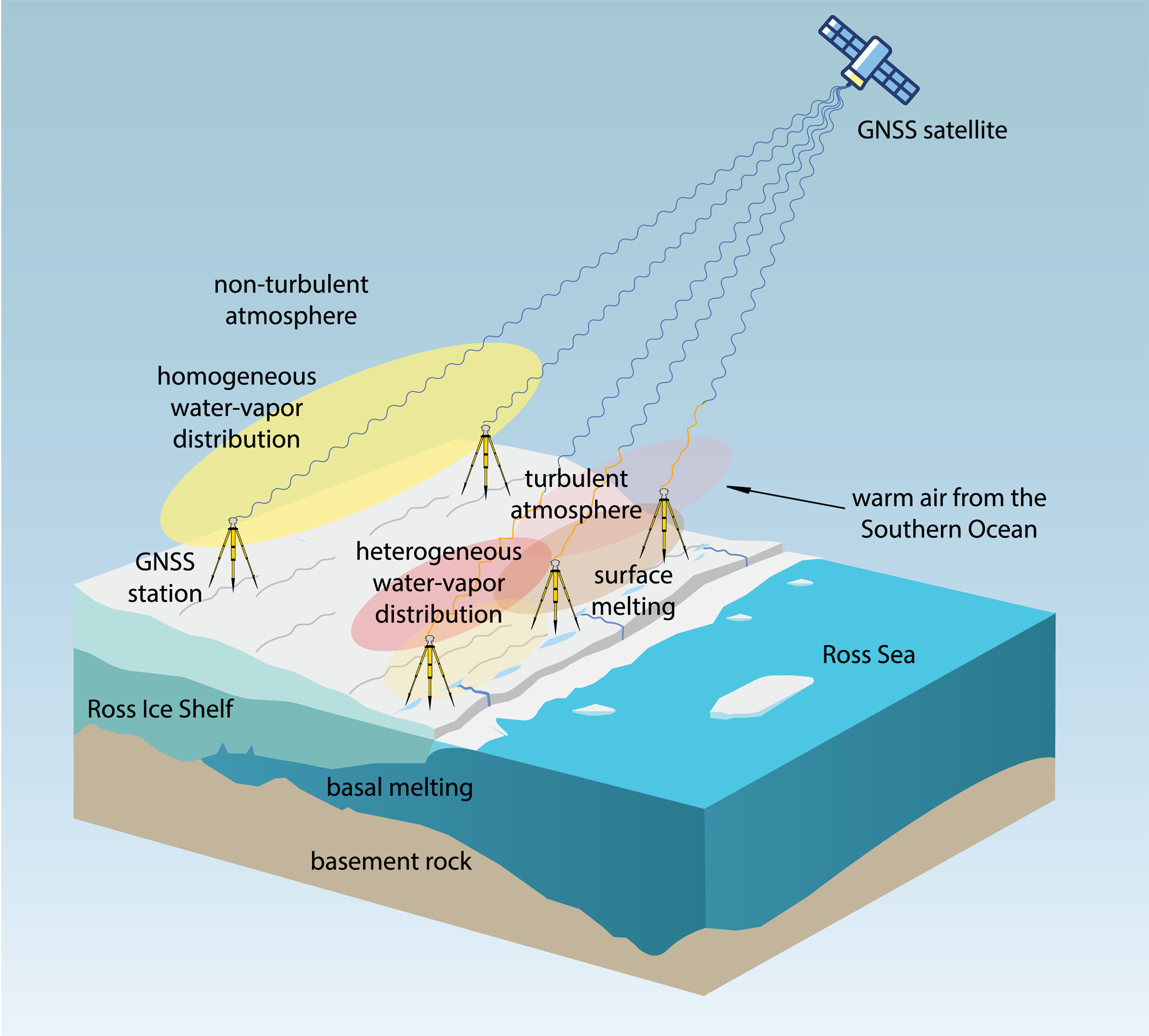
Observations suggest a major melting event at the Ross Ice Shelf was connected to atmospheric turbulence.
The Ross Ice Shelf in Antarctica typically melts on its underside as warmer ocean water flows beneath. But in January 2016, an unusual melting episode occurred on its topside.
A team from the Massachusetts Institute of Technology (MIT) Haystack Observatory used data from existing GNSS stations, in conjunction with 13 stations installed on shelf, to examine the turbulent state of the atmosphere. Key were delay differences at each station and between stations that showed the strength (or rockiness) of atmospheric turbulence over the ice shelf.
Wind, water vapor, and temperature variations drawn in by warm and humid air caused the surface to melt, with turbulence four times greater than usual during the 2016 surface melting event.
The study also demonstrated a novel application of the GNSS station data to remotely observe unusual atmospheric conditions.
The open-access study was published Feb. 27 in Geophysical Research Letters.
New test capability supports device manufacturers preparing for Xona’s commercial LEO navigation constellation.
Rohde & Schwarz is providing signal simulation capabilities supporting Pulsar, the next-generation satellite navigation service developed by Xona.
The new functionality enables manufacturers to test Pulsar capabilities in production settings using Rohde & Schwarz signal generators, providing an accessible pathway for validating and scaling devices with next-generation positioning, navigation and timing (PNT).
As demand grows for more precise and resilient navigation technology, the industry is preparing for a new generation of satellite signals. Xona’s Pulsar constellation, operating in low Earth orbit (LEO), is designed to complement existing GNSS infrastructure such as GPS by delivering stronger signals, improved accuracy, and enhanced resilience against threats and interference.
The capability will be available as a new software option for the R&S SMBV100B and R&S SMW200A vector signal generators, allowing engineers and manufacturers to test receiver compatibility with Pulsar signals as the new constellation enters scaled deployment. By adding Pulsar simulation to its test portfolio, Rohde & Schwarz enables device developers and manufacturers to begin validating compatibility with the emerging service.
“Navigation technology is entering a period of rapid evolution,” said Matt Hammond, North America satellite technology manager, Rohde & Schwarz. “By adding Pulsar signal simulation to our signal generator portfolio, Rohde & Schwarz is preparing our customers for the next evolution of satellite navigation. Our goal is to provide the scalable test infrastructure needed to bring these innovations from development into deployment.”
“Pulsar is designed to upgrade the global navigation infrastructure while remaining compatible with GNSS devices already in use today,” said Bryan Chan, co-founder and VP of strategy at Xona Space Systems. “Test and measurement solutions play an important role in enabling device manufacturers to evaluate compatibility as new signals become available. Rohde & Schwarz brings deep expertise in precision signal generation that helps make this possible.”
The R&S SMBV100B and R&S SMW200A vector signal generator will soon join Pulsar’s verified ecosystem program recognizing devices and testing solutions validated for compatibility with Pulsar signals. Rohde & Schwarz will showcase its navigation test solutions at Space Symposium 2026, taking place April 13-16 in Colorado Springs.