Category: Survey

  • SPH Engineering, Radar Systems advance aerial surveying

    SPH Engineering, Radar Systems advance aerial surveying

    SPH Engineering and Radar Systems, Inc. have developed the Zond Aero 500 NG, a versatile ground penetrating radar (GPR) system designed for both terrestrial and drone-mounted surveys. This dual-purpose GPR is suitable for various applications, including utility scanning, sinkhole detection, glaciology and geological studies.

    The Zond Aero 500 NG features dual-mode operation, allowing users to conduct both ground-based and airborne surveys. This flexibility enhances the data collection methods available to operators. The system includes a center frequency of 500 MHz, an operating bandwidth of 200-900 MHz (-12 dB), a sampling rate of 25,600 samples per second and a scan rate of 50 scans per second. It can achieve depth penetration of up to 4 m in average soil conditions, making it effective for a range of subsurface investigations.

    It is designed to deliver high-quality data through advanced electronics and real-time to enhance the signal-to-noise ratio significantly. This improvement enables the detection of finer details and deeper anomalies within the surveyed area. Additionally, the system is compatible with DJI Matrice 300/350 UAVs for airborne applications.

    The system’s data is recorded in real time as radiolocation profiles (radargrams), which are stored for further processing and interpretation. The data is saved in the standard geophysical SEGY format (.sgy) with geotagging for each trace to offer accurate analysis and reporting.

  • Emlid enhances land surveying capabilities

    Emlid enhances land surveying capabilities

    Photo: Emlid
    Photo: Emlid

    Emlid has released updates to its Emlid Flow mobile and cloud app for land surveying. The app now includes a full range of tools for earthworks, topographic and as-built surveys and features such as Surfaces support.

    When used with Emlid’s survey-grade Reach GNSS receivers, the upgraded Emlid Flow app aims to improve efficiency for land surveying and construction workflows. Key features added to Emlid Flow include advanced linework capabilities, inverse and traverse tools, polygon support and an auto-collection mode. The recently released Surfaces support allows surveyors to incorporate digital terrain models (DTM) into projects and calculate cut and fill values during stakeout operations.

    In developing these updates, Emlid seeks to create an uncluttered, intuitive interface for surveyors while maintaining all necessary controls and functionality. The app offers streamlined navigation and instant cloud syncing, enabling surveying professionals to complete tasks efficiently on their preferred device, whether a rugged Android smartphone or iPad. Projects prepared in the cloud are instantly accessible in the mobile app for field use, streamlining the entire survey process.

  • CHCNAV unveils GNSS receiver with IMU tilt compensation

    CHCNAV unveils GNSS receiver with IMU tilt compensation


    Photo: CHCNAV
    Photo: CHCNAV

    CHC Navigation (CHCNAV) has unveiled the i83 Pro, an inertial measurement unit (IMU)-real-time kinematic (RTK) GNSS receiver. This receiver combines GNSS capabilities with extensive compatibility options to address the diverse needs of surveying, construction and mapping professionals.

    The i83 Pro incorporates CHCNAV’s third-generation GNSS antenna and the latest iStar algorithm, designed to boost GNSS signal tracking efficiency by 30%, according to the company. With 336 channels supporting GPS, GLONASS, BeiDou, Galileo and QZSS constellations, it can achieve centimeter-level precision rapidly, even in challenging environments.

    The receiver offers comprehensive connectivity options, including built-in Wi-Fi, Bluetooth, NFC, 4G modem and UHF modem. These technologies support various GNSS surveying modes, such as RTK Networks NTRIP and UHF base-rover configurations. The i83 Pro is compatible with VRS, FKP and MAC for Network RTK for precise positioning across diverse operational settings.

    Engineered for challenging environments, the i83 Pro features an IP68-rated enclosure for dust and water protection, a compact and lightweight design for enhanced portability, a high-resolution color display for clear status information and a 20-hour battery life for continuous operation in rover mode.

    The i83 Pro offers optional Trimble RTX and OmniSTAR support, providing RTK-level accuracy without relying on a base station or VRS network. Additionally, it can be equipped with the optional Trimble MAXPro Positioning Engine for extended performance.

    CHCNAV will showcase this receiver at INTERGEO 2024 in Hall  3, Booth B3.052.

  • Surveyors join forces to complete two geodetic leveling projects

    Surveyors join forces to complete two geodetic leveling projects

    (Photo courtesy of Bob Kunes and Jeff Olsen)
    (Photo courtesy of Bob Kunes and Jeff Olsen)

    This is the story of two surveyors who met after retirement to accomplish two geodetic leveling projects in Maine and New Hampshire. Independent of each other, we had vacationed in those states, skiing and hiking. The idea of doing some geodetic leveling in that area appealed to us.

    We first re-leveled parts of a 1942 Coast & Geodetic Survey (C&GS) line between North Conway, New Hampshire, and Gilead, Maine, to honor the surveyors of World War II. During summer trips, we looked for the benchmarks along the line, NGS archive L9971, and figured out which ones were missing. We set new marks as needed. Leveling took place between September 9 and 22, 2013, archived by NGS as L28096, Second Order Class II.

    We used K&E Lovar yard rods — nice light wood rods with rod level, such as the U.S. Geological Survey (USGS) is believed to have used leveling up Mount Washington in 1925 — and a Zeiss Ni-2 level with 1:33 stadia interval (to convert yards to feet distance). Leveling up and over Hurricane Mountain Road NE of North Conway was a precursor to leveling up Mount Washington in 2014. We used a handheld GPS receiver to obtain the coordinates for marks that did not already have good accuracy. We obtained Online Positioning User Service (OPUS) coordinates for the reference marks on top of the mountain.

    Leveling through the Mount Washington “cow pasture.” In the inset, MAC 100, one of the USGS benchmarks along the Auto Road. (Photo: Mike Pelchat, NH DNCR)
    Leveling through the Mount Washington “cow pasture.” In the inset, MAC 100, one of the USGS benchmarks along the Auto Road. (Photo: Mike Pelchat, NH DNCR)

    After completing the 2013 releveling of the 1942 C&GS line, we wondered about releveling the 1925 USGS line up Mount Washington. We approached the general manager of the Mount Washington Auto Road, Howie “Weems” Wemyss, explained what we proposed to do, and asked for his buy-in. He approved the project enthusiastically, allowing us full access to the road for the project. On May 12, we began the level run from first-order benchmarks in Gorham, New Hampshire, and finished on June 8.

    Until this 2014 project, the elevations of Mount Washington were referenced to the National Vertical Datum of 1929 (NGVD 29) and were only available on paper from USGS. The professional purposes of the project were to connect Mount Washington to the North American Vertical Datum of 1988 (NAVD 88) and make the benchmark data available online from the National Geodic Survey (NGS). Two personal purposes were to continue enjoying the natural area and meet the challenges of the topography and weather.

    Deciding where to place each level setup on the steep terrain involved a compromise between time spent trying to read at the very top of the rod and a quicker setup decision that usually sacrificed 1.0-1.7 ft of the rod. The maximum vertical gain on the 10-ft rod was typically about 7.5 ft per setup, sighting high on the lower rod while sighting on the upper rod above the yard equivalent of 0.5 m — thereby reducing refraction errors per recommended procedures. Sight lengths on the Auto Road were as short as 10 ft, averaging 30 ft. Along the less steep terrain of Route 16 between Gorham and the Auto Road, leveling between marks set by NHDOT, sight lengths ranged around 150 ft. Temporary benchmarks on boulders were selected between the MAC marks on the Auto Road to keep the number of setups in a section below 30. That way, if the forward and backward runnings of a section misclosed, it was not a hopeless number of setups to rerun and isolate the error. The grade between MAC marks was 14% in two cases, otherwise around 10%. To eliminate 1-yd reading errors, 1-ft markings were painted on the side of the rod and read to x.1 ft before the 3-yd readings (top, middle and bottom wires), then the foot and yard readings were compared. The typical elevation difference between a MAC mark and a TBM or between TBMs was 150 ft. The typical time per setup was 4.5 minutes, depending on how far apart the turning points were.

    Project Diagram, 2014 Mount Washington leveling. ~8 miles SW along NH 16 from Gorham, 7.6 miles up the Auto Road. (Photo: Google Earth)
    Project Diagram, 2014 Mount Washington leveling. ~8 miles SW along NH 16 from Gorham, 7.6 miles up the Auto Road. (Photo: Google Earth)

    One bit of unwanted excitement occurred while the road crew was doing the annual rebuild of the 1-mile gravel section above Mile Post 5. The road workers pulled out the flagging at MAC 102, which is a bit hidden by vegetation. Evidently, it conflicted with the orange flagging they were also using. Leveling continued right past the disk for five setups until Bob noticed green paint on a boulder used as a turning point in the prior run. We had to reverse back to the mark. Fortunately, the section closed even with the extra setups.

    There are some beautiful small waterfalls along the road that are easier to admire when you are walking by, not trying to keep your vehicle on the road. One day, we spotted a momma bear and two cubs. One man stopped to reminisce about his time working with Brad Washburn while Brad was doing extensive surveying and mapping on the mountain.

    The USGS benchmarks are designated MAC 97 to MAC 104, “MAC” being the initials of the USGS party chief followed by a sequential number as the party progressed along the level line. There are lower numbered ones away from the Auto Road, and there used to be some higher numbered ones, which have since been destroyed.

    The project data was accepted, adjusted and published by NGS as archive L28128. The elevation of the highest and most visited summit mark, Mount Wash Reset (DP4904), by the cairn and the brown park sign, dropped 0.77 ft, referenced to NAVD 88 compared to its elevation referenced to NGVD 29. The NGVD 29 elevation published by USGS (solely in feet), based on the 1925 leveling, was 6,288.176 ft (divided by 3.2808333 ft/m to obtain 1,916.634 m). These values were rounded off to 6,288 ft and 1,917 m, respectively, for display on the summit sign.

    Jeff Olsen (on the left) and Bob Kunes in front of the observatory.
    Jeff Olsen (on the left) and Bob Kunes in front of the observatory.

    The NAVD 88 elevation for Mount Wash Reset, published by NGS based on this 2014 leveling, is 6,287.41 ft or 1,916.406 m. These values would round down to the next lower whole unit, changing the elevations that could be displayed on the park sign and making the mountain’s elevation lower. Since re-determining the mountain’s elevation was not a priority of this project, and a different elevation than the 6,288 ft that had been used for years would mean changing all those mugs, T-shirts and other tourist paraphernalia, we are not suggesting changing the elevation with which the public is familiar.

    All the differences of elevation observed between the various USGS benchmarks agreed within Second Order Class II limits with the previous 1925 work. At that level of precision (section closures less than or equal to 8 mm multiplied by the square root of the distance in km), the 2014 leveling did not reveal or detect vertical motion on the mountain, after an interval of 89 years. The project could always be re-run with first-order equipment and procedures, cutting the section closure error budget in half to 4 mm multiplied by the square root of the distance. Various marks could be observed in a regional high-precision geoid modeling campaign.

  • Topcon releases upgraded surveying software

    Topcon releases upgraded surveying software

    Photo: Topcon
    Photo: Topcon

    Topcon has released a new version of its computer-aided design (CAD) software suite, formerly known as MAGNET. With enhanced features and workflow improvements to the Office, Field and Tools modules, version 9 is also renamed under the Topcon software suite as the business retires the MAGNET brand.

    The software is designed for professionals such as surveyors, engineers, modelers, estimators, and project managers, aiming to improve productivity through integrated software capabilities and workflows. It can be used as standalone, office-based CAD software or as a cloud-connected solution that integrates field and office operations with Topcon or Sokkia survey instruments. The platform offers user-friendly and versatile configurations suitable for various applications.

    Topcon Office version 9 introduces new options for working with digital terrain models (DTMs), spot elevations and offset capabilities, enhancing versatility when handling 2D or 3D data sets. Improvements in Topcon Field include better productivity and stake reporting capabilities, advanced resection functionality for unknown control points, and a new offset routine for creating points that are not observable with a total station. Both Field and Office modules now support direct import and export with 12D XML file formats.

    Subscribers to the AllDayRTK high accuracy positioning network can now directly import and export RINEX data into Topcon Tools with a current Plus or RINEX subscription. Version 9 of Topcon Tools also features improved coordinate system functions, new traverse calculations, viewing options, and enhanced functionality for working with data in tabular view for reporting.

  • The need for trained geodesists is an international issue

    The need for trained geodesists is an international issue

    My previous newsletter highlighted activities associated with the Transportation Research Board ADK70 Standing Committee on Geospatial Data Acquisition Technologies. As I mentioned in the newsletter, Linda Foster, ESRI and president-elect of the National Society of Professional Surveyors (NSPS), highlighted how geodesy and surveying provide the foundation for digital twin products. Similar to the inverted geospatial pyramid depicted in my February 2022 GPS World newsletter, Foster’s presentation highlighted that geodesy is at the base of an inverted triangle. See my February 2022 and August 2024 newsletters for more details. Both diagrams emphasize the importance of geodesy and surveying in creating geospatial products and services.

    That said, on August 20, I had the opportunity to participate in the UN-GGIM: Europe webinar series: Quo Vadis Geodesy? webinar. Quo vadis is a Latin phrase meaning “Where are you going?” The webinar highlighted the importance of geodesy and the need for more trained geodesists. This is a topic that I have been highlighting for several years.

    Agenda for webinar. (Photo: UN-GGIM: Europe)
    Agenda for webinar. (All photos courtesy of UN-GGIM: Europe webinar.)

    Webinar write up

    Modern society relies heavily on satellite services for various critical functions, including economic development, the operation of critical infrastructure, and defense applications. Despite their clear and proven significance, these satellite services are at risk of degradation or failure due to the lack of resources provided to the global geodesy supply chain. It is crucial for decision-makers to understand the far-reaching implications of not strengthening this supply chain, which impacts societal, economic, and environmental applications. Additionally, these decision makers need clear pathways to address these vulnerabilities effectively.

    The Community of Interest on Geodetic Reference Frames – Europe, established by UN-GGIM: Europe, is dedicated to supporting the sustainment and growth of the geodetic profession. To address current knowledge gaps, we have organized this webinar featuring two insightful presentations. The first presentation will discuss the risks associated with weak geodetic foundations and their potential to compromise satellite services. The second presentation will introduce an initiative to launch an international Master of Science in Geodesy, emphasizing the importance of formal geodesy education in building robust geodetic foundations.

    There were three objectives of the webinar:

    1) Provide geo-experts resources to help them convincingly communicate and advocate for a strong global geodesy supply chain.

    2) Inform decision makers of the risks of not strengthening the global geodesy supply chain.

    3) Support the initiative of the IDEA-league universities to establish an international Master of Science in Geodesy.

    The webinar was recorded and can be found here. The presentations can be downloaded from the following weblinks:

    This newsletter is going to highlight some interesting items from the webinar, but I would encourage everyone to listen to the recording to obtain the full discussion.

    First, I would like to note that Ramon Hanssen included the geospatial inverted pyramid (designed by Dana J. Caccamise II, NGS Regional Geodetic Advisory) and the white paper titled “The Geodesy Crisis” (prepared by Mike Bevis collaborating with others) that documented the concern about the lack of trained geodesists in the United States (see February 2022 GPS World newsletter). Based on the presentation by Ramon Hanssen it appears that the lack of trained geodesists is also a concern of the European geospatial community.

    Image: Dana Caccamise II
    Image: Dana Caccamise II

    Nicholas Brown, Head of Office, United Nations Global Geodetic Centre of Excellence, did a nice job of explaining the importance of geodesy in everyday activities. He highlighted how GNSS is a critical infrastructure for telecommunications, emergency services, and financial exchanges. In my opinion, GNSS and geodesy are unsung heroes of everyone’s daily activities.

    He provided a scenario that would affect almost everyone in their daily routines.

    Imagine a scenario without GNSS. (Photo: Nicholas Brown)
    Imagine a scenario without GNSS. 


    This highlights the importance of geodesy and the need to increase the number of trained geodesists in the world. My July 2020  “First Fix” article in GPS World discussed the need to increase the number of trained geodesists in the United States, and it appears the same issue is a concern of many individuals in Europe. Ramon Hanssen and Peter Teunissen, TU Delft, presented a way forward for Europe. The following are some highlights of the presentation but, again, I would encourage readers to download the slides and webinar for more details.

    The presentation described “The IDEA League,” which is a strategic alliance between five European universities of technology: TU Delft, ETH Zurich, RWTH Aachen, Chalmers University, and Politecnico di Milano. One goal of the partnership is to re-establish Europe as a technological and scientific leader by integrating academic resources and knowledge. The concept includes pooling resources for collaborative and complementary programs for teaching students and researchers.

    The alliance established an initiation team to develop a proposal that included the following:

    1. Establish a joint international European MSc program in Geodesy.
    2. Combine resources of universities, scientists, and educators in Europe.
    3. Respond to the urgent need for academic geodesists.
    4. Inspire collaboration via complementary fields.

    The group sent a questionnaire to stakeholders in the geodetic job market to obtain an understanding of the need for trained geodesists. The responses to the questionnaire highlighted the urgent need for more trained geodesists. Two important responses by stakeholders were (1) 72% perceived the current availability of MSc graduates in geodesy to be unsatisfactory and (2) 83% expects the demand for (academic) professionals with expertise in geodesy to grow in the foreseeable future.

    Photo: Nicholas Brown

    As mentioned above, 72% perceived the current availability of MSc graduates in geodesy to be unsatisfactory. The questionnaire asked, “What challenges or gaps do you face in recruiting qualified geodetic professionals?”

    Photo: UN-GGIM

    There were many responses to this question; the image below provides a few examples that were presented at the webinar.

    Challenges and gaps. (Photo: UN-GGIM)

    Photo:

    The stakeholders provided reasons why they believe that the demand for geodesists will increase in the future. The list below provides a breakdown of the reasons provided by the stakeholders. The top two reasons were technological advancements and digital transformation. Concerns with consistency in the digital delivery of geometric products were highlighted in my August 2024 newsletter.

    We now live in a world where everything is digital. Today, most surveying and mapping instruments collect and generate data in digital format. This paradigm has affected how surveyors, geodesists, and engineers provide their products and services. So, it makes sense that advancements in technology and the transformation of digital data would be important to stakeholders.

    The stakeholders were asked their opinion on what expertise is needed by geodesists to meet their requirements. The image below shows the responses of the stakeholders. There were six expertises that exceeded 50%:

    • Quality (Precision, Accuracy) – 75.8%
    • Sensors and Techniques – 63.6%
    • Data Analytics – 60.6%
    • Mathematical Fundamentals – 58.6%
    • Reference Frames – 58.6%
    • GIS and Geo-Databases – 52.5%

    The group provided a preliminary program design for a MSc Geodesy. See the image below.

    Draft overview MSc Geodesy. (Photo: UN-GGIM)
    Draft overview MSc Geodesy. 

    As in all partnerships and collaborations, there are challenges. The group is working together to overcome these challenges. The stakeholders could help by supporting the IDEA League concept and proposal.

    Photo:

    Nicholas Brown’s presentation, “You, Me and Geodesy,” provides information that others can use to explain how the global geodesy supply chain is fundamental to what they do and how critical it is to our daily lives. He describes five weaknesses (see the box titled “Weakness in Geodetic Message”) that need to be addressed to improve the message of why it is important to increase the geodetic capacity in the world. I have provided a short summary below, but readers should listen to the webinar for more details.

    • Evidence – There is no clear, understandable evidence to explain the importance of investing in geodesy to decision makers.
    • Resources – Leadership cannot make the business case to invest in geodesy without good evidence.
    • Awareness – There is a need to communicate the importance of geodesy to other science agencies and scientists in different fields of study. For example, climate change is highly dependent on geodesy for measuring sea level rise, changes in gravity, ice melt, and the location of Earth’s center of mass.
    • Capacity – Capacity development in geodetic science needs to be strengthened everywhere not just in developing countries.
    • Governance – The scientific geodetic community has done an exceptional job of managing the geodetic infrastructure (e.g., International Association of Geodesy) but they are expected to do too much. During Nicholas Brown’s presentation, he mentioned that, in his opinion, an improved governance model could help advance geodesy around the world. He mentioned the need to have a governance model like the World Meteorological Organization (WMO). WMO members contribute resources to the organization, technical commissions are established to address issues, and operational support and resources are provided to implement capacity development programs.


    Weakness in geodetic message. (Photo: UN-GGIM: Europe webinar.)
    Weakness in geodetic message.

    The UN-GGIM: Europe webinar series: Quo Vadis Geodesy webinar highlighted the importance of geodesy and the need for more trained geodesists. Anyone reading my GPS World newsletters knows that I have been highlighting the need for more trained geodesists in the United States for several years. This newsletter highlighted interesting items from a webinar that discussed the need for more trained geodesists in Europe. Again, I would encourage everyone to listen to the recording to obtain the full discussion.

  • Launchpad: GNSS antennas and receivers,  UAV upgrades, defense solutions and more

    Launchpad: GNSS antennas and receivers, UAV upgrades, defense solutions and more

    A roundup of recent products in the GNSS and inertial positioning industry from the August 2024 issue of GPS World magazine.


    SURVEYING & MAPPING

    Upgraded RTK Rover
    Features MFi certification

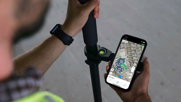
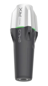
    The Reach RX Network real-time kinematics (RTK) rover has been upgraded to include new MFi (Made for iPhone/iPad) certification and is fully compatible with ArcGIS, QGIS and other GIS apps for both iOS and Android. Reach RX can be seamlessly integrated into GIS workflows to help industry professionals and teams collect accurate geodata at scale.

    The Reach RX offers precise positioning while receiving corrections through NTRIP and tracks GPS/QZSS, Galileo, GLONASS and BeiDou. It gets a fix in less than 5 seconds, delivering centimeter-level accuracy even in challenging conditions.

    It can be used for engineering, utility inspection, landscaping and other projects of any scale. According to the company, the rover will soon be compatible with QField, Blue Marble’s Global Mapper, Mergin Maps, Avenza Maps and more.

    The Reach RX weighs 250 grams; is IP68-rated, waterproof and dustproof; and withstands temperatures from -20° C to +65° C.Emlid, emlid.com

    Photogrammetric Software
    Upgraded coordinate system functionalities

    3Dsurvey 3.0 is an all-in-one photogrammetric software solution designed to unify lidar sensors, cameras on UAVs and various ground control points. Users can transition between orthophotos, point clouds and textured meshes.

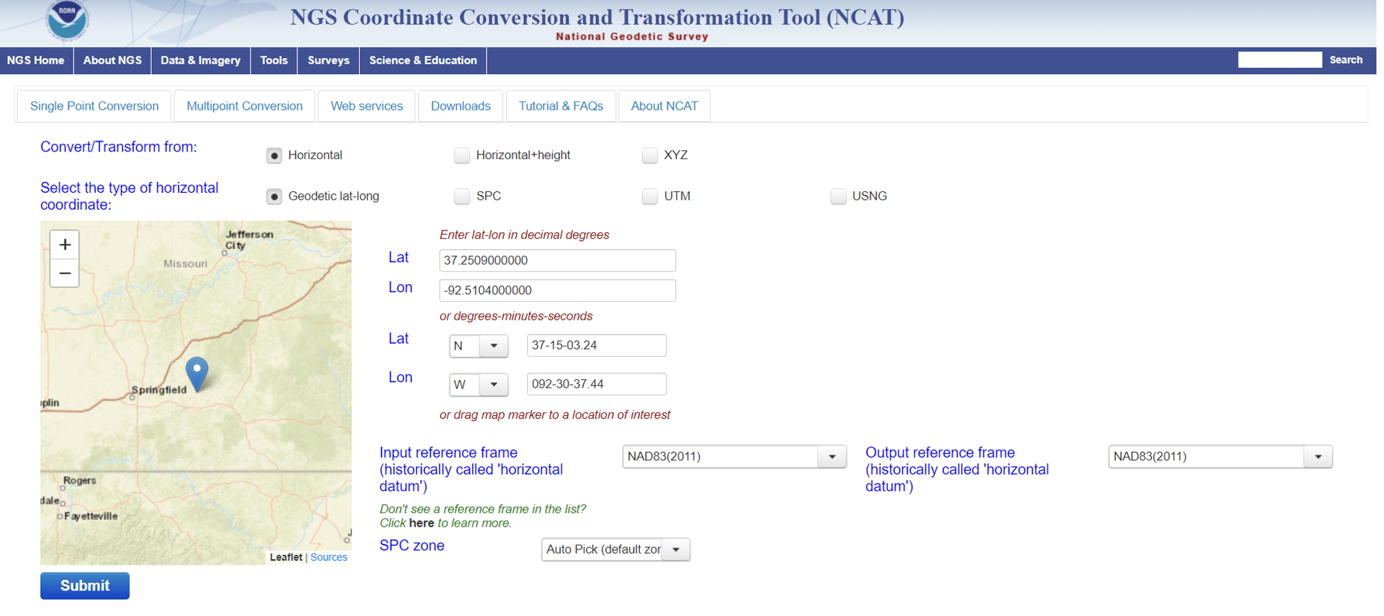
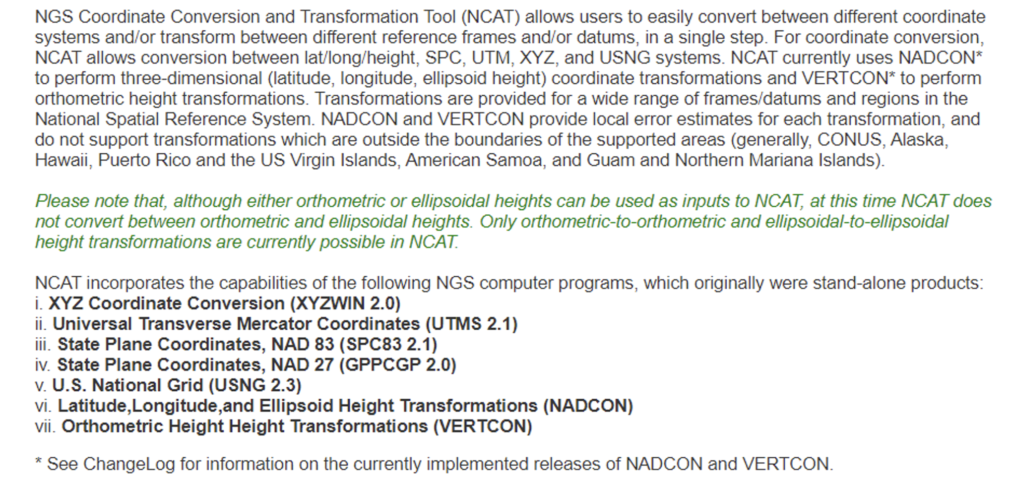
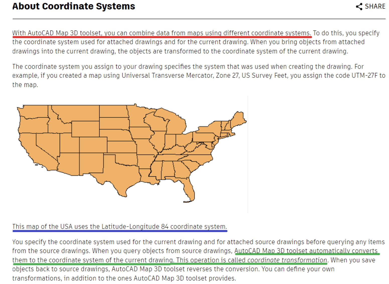
    Version 3.0 features upgraded coordinate system functionalities to obtain georeferenced spatial data without local transformations.

    It includes improved coordinate system support, which handles transformations requiring special grid files and offers accurate GPS-to-local coordinate conversions. Additionally, the platform can automatically fetch missing geoid models.

    The revamped coordinate system selection process includes presets for users to find the correct system by entering their country name, with the appropriate settings applied automatically. It has PRJ file support to enhance compatibility with various GIS standards. 3Dsurvey, 3dsurvey.si

    RTK Evaluation Kit
    Includes L1+L2 RTK GNSS

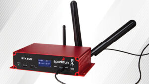
    This real-time kinematics (RTK) evaluation kit (EVK) serves as a development platform for fixed or mobile high-precision positioning and navigation needs.

    The RTK EVK comes with a range of options for prototyping, including L1+L2 RTK GNSS, with L-Band correction built-in if needed, running on an agile processor.

    It features custom open-source software pre-loaded with RTK Everywhere firmware. Users can configure the EVK as an RTK base and push corrections to an NTRIP Caster or use corrections delivered through WiFi or Bluetooth.

    The integrated u-blox NEO-D9S offers L-Band reception and access to correction services such as PointPerfect. The u-blox LARA-R6001D provides global cellular connectivity, and Zero-Touch RTK offers users a simple way to receive corrections. Users can register the device and enable PointPerfect — no NTRIP credentials are required. Sparkfun Electronics, sparkfun.com

    GNSS Receiver
    With tilt compensation

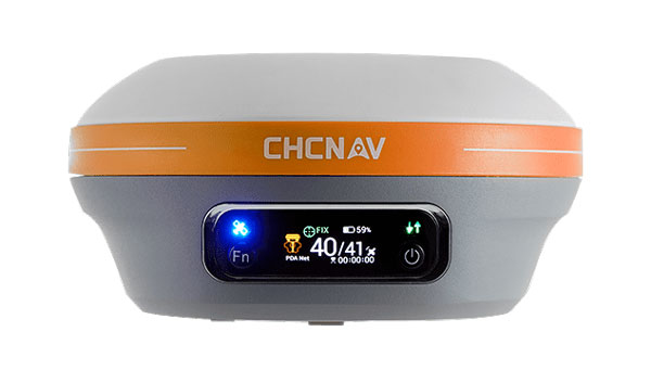
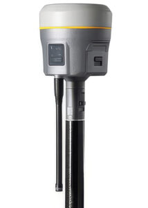
    The R980 features communication capabilities to support uninterrupted field operations. It can be used for land surveying, transportation infrastructure, construction, energy, oil and gas, utilities and mining projects.

    The system features Trimble’s ProPoint GNSS positioning engine and inertial measurement unit (IMU)-based tilt compensation, making it suitable for dense urban environments and under tree canopy, removing the need to level the pole when capturing data points.

    It includes a dual-band UHF radio and an integrated worldwide LTE modem for receiving corrections from a local base station or VRS network. It supports the Trimble Internet Base Station Service (IBSS) for streaming RTK corrections using Trimble Access field software and features Trimble IonoGuard technology, which mitigates ionospheric disturbances for RTK GNSS. Trimble Geospatial, geospatial.trimble.com

    Nautical Chart Production
    Generate charts in PDF/TIF from ENC data

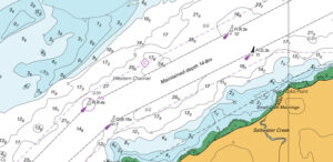
    CARIS AutoChart, a nautical chart production solution, is tailored to the needs of nautical chart producers. It can automatically generate charts in PDF/TIF from ENC data. Users can seamlessly import data from ENC files to create comprehensive nautical charts in PDF and/or TIF format. CARIS AutoChart can generate chart templates from existing chart portfolios maintained with CARIS paper chart composer or CARIS HPD paper chart editor.

    The software is designed to accommodate the unique needs of chart production facilities of all sizes. It can be used by hydrographic offices, port or waterways authorities.Teledyne Geospatial, teledyneimaging.com

    Upgraded GIS Platform
    Featuring native database integrations

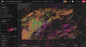
    Felt 3.0 includes new features and native database integrations to improve the capabilities of geographic information systems (GIS). It provides modern GIS tools for teams to visualize, analyze and present important insights and map data relevant to their operations.

    Operators can directly connect Postgres/PostGIS and Snowflake databases for automated live data updates. The API allows users to create and style elements and listen to map updates via webhooks, while providing a Python SDK for professionals to continue to work in their preferred tools. Felt, felt.com


    UAV

    Gimbaled Camera
    For UAV missions

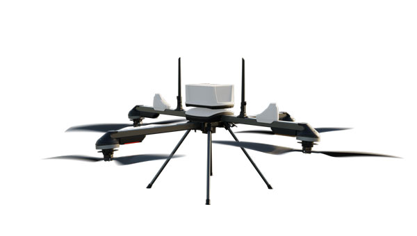
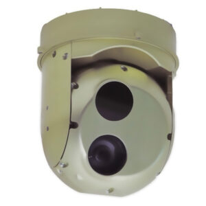
    The Gimbal 155 is a gimbaled camera designed for the UAV Survey Mission program. The GOS-155 meets UAV requirements for surveillance and rescue missions. Its optimized size, weight and power (SwaP) profile, advanced day and night ISR imaging, and embedded video processor make it ideal for any mid-sized UAV — whether VTOL or winged. With its low weight of 1.8 kg, and 155 mm, UAV platforms can increase endurance without sacrificing optical performance.

    The GOS-155 two-axial gimbal is an EO/IR system, comprising a 30x optical zoom HD (1280 x 720) visible camera paired with a fixed focal length uncooled thermal LWIR (1280 x 1024) camera. This allows users to collect intricate visuals across visible and infrared spectrums.

    It includes embedded video processing with electronic stabilization and object tracking and can be integrated with external GPS/INS with real-time target location at 20 m across multiple environments, and around 5 m using UAVOS’ Ground Control Station software. UAVOS, uavos.com

    Tactical Grade INS
    Tailored to unmanned systems

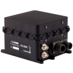
    The FN 200C combines multiple functions into a single integrated platform. It features a three-in-one strapdown system compromising motion reference unit (MRU), attitude and heading reference system (AHRS) and inertial navigation system (INS) capabilities for precise positioning, velocity and orientation data in both static and dynamic movements.

    It is equipped with fiber optic gyroscopes (FOG) and MEMS accelerometers. The FN 200C’s inertial measurement unit (IMU) offers accurate and reliable navigation data even in challenging conditions. The system supports various correction methods such as SBAS, DGPS, RTK, and PPP for real-time navigation and positioning in a wide range of applications.

    The FN 200C utilizes NovAtel OEM7, u-blox ZED-F9P or Septentrio mosaic-H GNSS receivers to provide precise positioning information across multiple GNSS constellations. With embedded anti-jamming and spoofing features, the FN 200C offers reliable operation in environments where signal interference may be present.

    The FN 200C is ideal for unmanned systems applications, including land-based surveying, aerial mapping, maritime navigation and more, delivering precise and reliable navigation data to meet the most demanding requirements. According to FIBERPRO, the system’s advanced technology, robust design and comprehensive feature set ensure that it will revolutionize navigation and operation in today’s dynamic and challenging environments. FIBERPRO, fiberpro.com

    Upgraded UAV
    With a modifiable flight controller

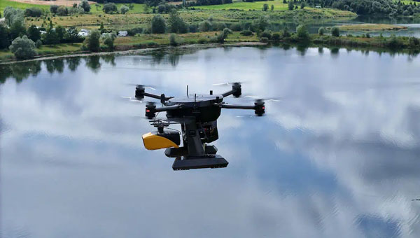
    The RDSX Pelican extended-range hybrid vertical take-off and landing (VTOL) delivery UAV is now offered with an easily modifiable flight controller, designed for users to more readily integrate customized flight systems and companion software.

    The RDSX Pelican combines the reliability and flight stability of a multirotor craft with the extended range of a fixed-wing airframe. Its customizable payload bay can be factory-integrated with the A2Z Drone Delivery RDS2 commercial delivery winch to support a variety of logistics operations.

    Engineered to operate within the FAA’s 55-pound max takeoff weight for Part 107 compliance, the Pelican is rated to carry payloads up to 5 kg on operations up to 40 km roundtrip. The flexibility of the Pelican’s cargo bay makes it ideal for logistics missions or deployment with payloads customized for aerial mapping, UAV inspection, forestry services, search and rescue operations, water sample collection, offshore deliveries, mining and more.

    With the RDSX Pelican now operating on the Cube flight controller (CUAV X7+), users can integrate their preferred systems — including ground control software, radio beacons and other companion software systems. A2Z Drone Delivery, a2zdronedelivery.com

    GNSS Positioning Modules
    Compatible with UAVs and robotics

    The Linnet ZED-F9P is built around u-blox’s ZED-F9P RTK module. It offers multiband signal reception including GPS L1 and L2 for precise positioning, even in areas with low satellite coverage. In addition to USB-C connectivity, it features UART, SPI and I2C interfaces for easy integration into a variety of UAV and robotics platforms.

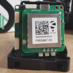
    Linnet Mosaic X5 RTK-GNSS module is based on Septentrio’s mosaic-X5 module, with multifrequency signal tracking including GPS L5. The module features an onboard CPU that runs a full internal web-based user interface for configuration and monitoring, as well as integrated NTRIP corrections. Other capabilities include built-in anti-jamming and anti-spoofing protection and a spectrum analyzer. Systork, systork.io


    MOBILE

    “Patch-In-A-Patch” Antenna
    Maintains dual-band L1/L5 performance

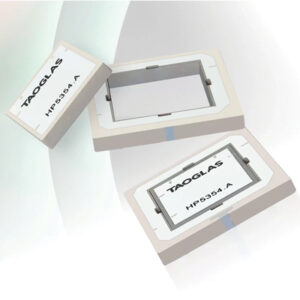
    Inception is a new GNSS L1/L5 ultra-low-profile “patch-in-a-patch” antenna. The HP5354.A offers dual-band stacked patch performance in a single 35 mm x 35 mm x 4 mm form factor. This design integrates the second antenna within the first, eliminating the need for stacking parts and reducing the antenna height by 50%.

    The HP5354.A antenna features a passive, dual-feed surface mount design (SMD) to decrease weight and conserve horizontal space. This makes it suitable for GNSS applications requiring high precision and limited space. The antenna improves positioning accuracy from 3 m to 1.5 m while maintaining dual-band L1/L5 performance.

    With a passive peak gain of 2.61 dBi, the HP5354.A can be used for GPS L1/L5, BeiDou B1, Galileo E1, and GLONASS G1 operations. Its dual-feed design maintains circular polarization gain even when the antenna is de-tuned or requires in-situ tuning.

    It is ideal for applications such as asset tracking, smart agriculture, industrial tracking, commercial UAVs and autonomous vehicles. The HP5354.A uses Taoglas’ custom electro-ceramics formula, ensuring high-quality performance and seamless integration into devices requiring high-precision GNSS.

    The Taoglas HC125A hybrid coupler can combine the dual feeds for the L1 patch, offering high RHCP gain and optimal axial ratio for upper constellations including GPS L1, BeiDou B1, Galileo E1 and GLONASS G1. The Taoglas TFM.100B L1/L5 front-end module can be incorporated into the device PCB, aiming to save valuable real estate and up to two years of complex design work, according to the company. Taoglas, taoglas.com

    Waterproof GNSS Antenna
    Built-in LNA

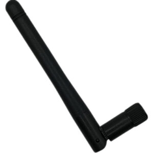
    The external antenna features an adhesive mount and sealed IP67-rated waterproof protection. It is an active GPS/GNSS antenna that includes a built-in low noise amplifier (LNA) for enhanced performance, making it ideal for applications where the receiver is close to the antenna and in environments where signal strength is strong, such as open areas with a clear line of sight.

    This type of antenna can amplify weak signals received from satellites by improving signal quality and reducing noise. It requires an external power source to operate the built-in LNA and is less sensitive to signal loss due to longer cable lengths. It is connected to an SMA connector at the end of a 3 m pigtail. The antennas can be used in navigation, location-based services and fleet management applications. Amphenol RF, amphenolrf.com


    DEFENSE

    AI and Quantum-Powered Navigation System
    When GPS signals are compromised

    AQNav is designed for navigation across air, land and sea when GPS signals are jammed or unavailable.

    AQNav is a geomagnetic navigation system that uses proprietary artificial intelligence (AI) algorithms, powerful quantum sensors and the Earth’s crustal magnetic field. The system seeks to provide an un-jammable, all-weather, terrain-agnostic, real-time navigation solution in situations where GPS signals are unavailable, denied or spoofed.

    The system uses extremely sensitive quantum magnetometers to acquire data from Earth’s crustal magnetic field, which exhibits geographically unique patterns. It uses AI algorithms to compare this data against known magnetic maps, allowing the system to quickly and accurately find its position.

    It is available globally, does not rely on visual ground features or satellite transmissions to function and is not affected by weather conditions. AQNav can be integrated into a wide variety of platforms. Its passive technology emits no electronic signals, which reduces the aircraft’s detectability. SandboxAQ, sandboxaq.com

    PNT Solution
    Operates with or without GNSS signals

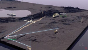
    TRNAV is a terrestrial navigation solution designed to operate with or without GNSS signals.

    It establishes a mesh network of ground stations capable of operating independently from GNSS by using precise pre-established locations or connecting to GNSS when available. TRNAV’s synchronized timing system ensures a minimal drift of 10 ns during a week without GNSS.

    The system features a re-synchronization capability that allows the entire network to be updated instantly when just one station reconnects to a GNSS satellite, maintaining high precision across all platforms. Users can integrate mobile stations to enhance network flexibility and range, with the potential to cover distances up to 250 km.

    TRNAV also offers a high-bandwidth communication channel for communication capabilities within the established network. The system employs AES-256 encryption and advanced waveform technologies, including DSSS/FHSS for robust and secure operations in challenging environments. TUALCOM, tualcom.com

    Software-Defined Radio
    Designed for mission-critical systems

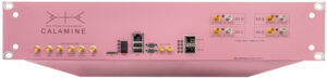
    Calamine is a four-channel wide tuning range software-defined radio (SDR) that can be integrated into mission-critical systems for the defense, GNSS, communications and test and measurement markets.

    The SDR offers a tuning range from near DC to 40 GHz with four independent receiver radio chains, each offering 300 MSPS sampling bandwidth. It is tailored to government, defense and intelligence communities and civil users with direct applications for radar systems, signal intelligence, spectrum monitoring and satellite communications systems. Per Vices, pervices.com

    C-UAS Solution
    For electronic warfare

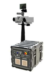
    The Skyjacker is a multi-domain electronic warfare counter unmanned aerial system (C-UAS), suitable against swarms and high-speed threats. It is designed as a response to threats posed by UAVs in the battlespace and at sensitive installations.

    Skyjacker alters the trajectory of a UAS by simulating the GNSS signals that guide it toward its target.

    Skyjacker is particularly well suited to countering saturation attacks, such as swarming UAVs. The system also can defeat isolated drones piloted remotely by an operator and deliver effects at ranges from 1 km to 10 km (6 mi).

    It can be integrated with an array of sensors, such as optronic sights, radars, radiofrequency detectors, lasers, communication jammers and other effectors. Skyjacker can be deployed as a mobile version or interconnected with existing surveillance and fire control systems on land vehicles or naval vessels. Safran Electronics & Defense, safran-group.com

  • YellowScan, Xer Technologies partner for underwater topography mapping

    YellowScan, Xer Technologies partner for underwater topography mapping

    Photo: YellowScan
    Photo: YellowScan

    Xer Technologies and YellowScan have partnered to integrate the YellowScan Navigator bathymetric system into Xer Technologies’ UAVs. This collaboration aims to enhance UAVs’ capabilities for conducting long-range bathymetric surveys and underwater inspections, which are essential in various fields such as environmental monitoring, coastal management, and infrastructure development.

    The integrated system allows users to collect high-resolution and accurate bathymetric data, even in challenging aquatic environments. YellowScan’s green laser lidar technology is a key component of this system, providing precise underwater mapping capabilities. Xer Technologies’ UAVs are designed for extended flight durations and can operate for more than two hours, facilitating coverage of larger survey areas in a single mission. This feature is particularly beneficial for projects that require extensive data collection over vast aquatic regions.

    The YellowScan Navigator can achieve a precision of 3 cm and can operate at a maximum altitude of 100 m above ground level. The laser has a range of up to 120 m and features a scanner field-of-view of 44 °. It weighs 3.7 kg.

  • Skyfront releases UAV magnetometer

    Skyfront releases UAV magnetometer

    Photo: Skyfront
    Photo: Skyfront

    Skyfront has released the Skyfront MagniPhy, a UAV magnetometer designed for surveying, mineral prospecting, locating orphaned wellheads, and detecting landmines and unexploded ordnance (UXO). The MagniPhy aims to enhance data quality, efficiency, and safety in these applications.

    The Skyfront MagniPhy features a new enclosure and universal attachment mechanism compatible with third-party magnetometer sensors and a variety of UAVs, including DJI, ArduPilot, and PX4-based models. Developed in collaboration with Geometrics, of the MagArrow II UAS-enabled magnetometer, the MagniPhy is available for existing MagArrow users and other UAV magnetometer operators through retrofit services or as a new kit for seamless integration.

    The MagniPhy offers improved data quality and enhanced ability to detect subterranean objects, thanks to its rigid attachment, which maintains constant magnetometer heading during flight and minimizes magnetic noise. Its aerodynamic design reduces motion-induced noise and enhances performance in high winds. Additionally, the device is highly portable, folding from 16.4 ft to 1.4 ft to fit in carry-on luggage, and features swappable batteries providing up to eight hours of operation.

    Skyfront’s high-endurance hybrid gas-electric multicopter UAVs complement the MagniPhy’s capabilities, enabling extensive magnetic surveys. These systems are deployed globally for various applications, including finding abandoned oil and gas wellheads in the U.S. and detecting landmines and UXO in Ukraine. The MagniPhy offers a safer and more efficient solution to traditional helicopter surveys and short-duration battery-powered UAVs.

  • TRB ADK70 Standing Committee on Geospatial Data Acquisition Technologies summer meeting

    TRB ADK70 Standing Committee on Geospatial Data Acquisition Technologies summer meeting

    My last newsletter highlighted the products on the National Geodetic Survey (NGS) Alpha Preliminary Products site. The alpha site provides products that individuals can use to better understand the products that will be distributed as part of the new, modernized National Spatial Reference System (NSRS).

    This newsletter is going to highlight activities associated with the Transportation Research Board’s ADK70 Standing Committee on Geospatial Data Acquisition Technologies. This committee is concerned with applications of high-accuracy geospatial data acquisition technologies in support of the digital infrastructure for the design and construction of transportation facilities. Members have various backgrounds and expertise and are located in different regions of the United States.

    The committee holds two meetings a year, one at the January TRB Annual Meeting held in Washington, D.C., and a summer meeting in different locations each year in late July.

    This year, the meeting of the Geospatial Acquisition Technologies in Design and Construction Summer Committee was held on July 29-31, 2024, in Washington, D.C. Topics included new technologies on data collection, modeling and plan delivery. There were updates from organizations such as the National Geodetic Survey, the Federal Highway Administration, the American Association of State Highway and Transportation Officials and various state departments of transportation on technology, standards, specifications and industry needs. See the agenda below.

    Photo: NGS schedule 1

    Photo: NGS schedule 2

    Photo: NGS schedule 3

    I first got involved with this committee in 1999, when I worked for NGS. One may ask, why would a geodesist be interested in a committee that focuses on the design and construction of transportation facilities? In my opinion, this is an important committee that addresses geospatial issues that affect all users of geospatial data, not just state Department of Transportation (DOT) surveyors and engineers.

    As anyone who has been reading my GPS World Survey Scene newsletters knows, I remind everyone that “geodesy is the foundation for all geospatial products and services.” As previously stated, this committee is concerned with applications of high-accuracy geospatial data acquisition; therefore, surveyors and geodesists must be involved to address issues associated with positioning. Anyone using or acquiring geospatial data should be interested in this committee’s activities.

    During AKD70 summer workshop meetings, participants talk with technical experts about the latest advancements in geospatial data acquisition technologies. I would encourage anyone interested in high-accuracy geospatial data acquisition technologies to learn more about this TRB committee, which is currently chaired by Wei Johnson, South Carolina DOT.

    Digital delivery geometric consistency concerns

    One session at the meeting discussed concerns with digital delivery geometric consistency. We now live in a world where everything is digital. Today, most surveying and mapping instruments collect and generate data in digital format. This paradigm has affected how surveyors, geodesists, and engineers provide their products and services. So, what is the issue with digital delivery geometric consistency?

    As I previously stated, I am a geodesist, so I think in geodetic coordinates (latitude, longitude, ellipsoid and orthometric height) or cartesian coordinates (X, Y and Z).

    Photo: NGS
    Three-Dimensional Positioning (XYZ). (Photo: NGS)

    From NOAA Technical Memorandum NOS NGS 59. (Photo: NGS)
    Orthometric, Ellipsoid and Geoid Heights from NOAA Technical Memorandum NOS NGS 59. (Photo: NGS)

    Looking at the diagram in the above image, I would like to highlight that the orthometric height is measured from the geoid along a curved line. The curved line is based on an infinite number of geopotential level surfaces that exist between the geoid, which is a geopotential surface, and the mark located on Earth’s surface. This is why gravity plays a part in determining the orthometric height of a mark.

    This means that leveling height differences are not the same as ellipsoid height differences. To compute a GNSS-derived orthometric height, a geoid height is subtracted from the GNSS-derived ellipsoid height. This is only an approximation because of how the two heights are measured but, at this moment, it is accurate enough for surveying and mapping applications.

    What about computing an ellipsoid height from an orthometric height? The ellipsoid height can be computed using the equation h = H + N (ellipsoid height = orthometric height + geoid height). Once you have an ellipsoid height, you can compute the X, Y, and Z coordinates of the mark. Orthometric heights derived from leveling data are one-dimensional (orthometric height only), whereas GNSS-derived coordinates are three-dimensional (XYZ or latitude, longitude, ellipsoid height). Therefore, to compute a cartesian coordinate (XYZ), from a leveling-derived height users must generate a latitude and longitude of the mark. It is important to use the appropriate geoid height and to record that information in a metadata file.

    NGS has developed web-based applications to convert coordinates between different coordinate systems and transform between different reference frames and/or datums. See the box titled “NGS NCAT Web Tool.” I described the NCAT web tool in my October 2019 and September 2023 GPS World newsletters.

    NGS NCAT web tool. (Photo: NGS)
    NGS NCAT web tool. (Photo: NGS)

    Photo: NGS o:
    Photo: NGS

    So, from a geodesist’s point of view, there is no issue with digital delivery geometric consistency if the appropriate tools are correctly used to convert coordinates between different coordinate systems and transform them between different reference frames and/or datums. That said, unique coordinate systems may be used by engineers to create 2D and 3D as-built drawings, such as blueprints and models. This should not be a problem for developing a transformation model if the appropriate information is available.

    The AutoCAD Map 3D website states that users can combine data from maps using different coordinate systems (see the box titled “Excerpt from AutoCAD Map 3D Site”).  The site states that “AutoCAD Map 3D toolset automatically converts them to the coordinate system of the current drawing.”  This is an indication that CAD routines are working on handling different coordinate systems.

    That said, users should make sure that the conversions and transformations are using the correct formulas and parameters. For example, I would like to know what defines the Latitude-Longitude 84 coordinate system that is highlighted in the box. I am not suggesting that anything is incorrect in the definition of the coordinate system. I am just saying that I do not know what the statement means; I would need more information before I can use the data.

    Excerpt from AutoCAD Map 3D 2025 site.
    Excerpt from AutoCAD Map 3D 2025 site.

    That said, ESRI and Autodesk, two industry leaders, have created a partnership to integrate GIS and Building Information Models (BIM), which seeks to create an integrated and collaborative workflow that connects data sources. ESRI denotes this as ArcGIS GeoBIM.

    Representatives from ESRI and Autodesk participated in the meeting. During the meeting, Linda Foster, ESRI and President-Elect of the National Society of Professional Surveyors (NSPS), gave a presentation that included a discussion of the ArcGIS GeoBIM web-based tool. Linda highlighted how geodesy and surveying provide the foundation for Digital Twin products. Her presentation included a diagram that I have recreated below.

    Notice that geodesy is at the base and digital twin is at the top of the inverted triangle. See the box titled “Geodesy Provides the Foundation for all Geospatial Products and Services.” The diagram is like the one I highlighted in my February 2022 GPS World Newsletter to emphasize the geodesy crisis. Both diagrams emphasize the importance of geodesy and surveying in creating geospatial products and services. It is encouraging to see that ESRI and Autodesk are working together to understand the needs of both communities. This will lead to the development of an improved system.

    Photo:
    Image: Dave Zilkoski — based on Linda Foster’s presentation at the TRB AKD70 summer meeting on July 30, 2024.

    From a geodesist’s viewpoint, there does not seem to be a problem with digital delivery geometric consistency. Of course, I know that it is not as simple as I am making it. I realize that the “devil is in the details,” which means that something that appears to be simple will identify issues that will have to be dealt with during development and implementation. During the meeting, it was announced that the TRB AKD70 Committee is developing a webinar titled “Resolving ambiguities between 3D virtual models and the real world” to make people aware of the issues.


    Proposed Webinar

    Proposed title: “Resolving ambiguities between 3D virtual models and the real world”
    Proposed description: The transportation industry is rapidly moving towards achieving digital product delivery and digital as-built objectives in the Civil Infrastructure sector. They are doing this by adopting a 100% end-to-end digital, asset-centric, interoperable data flow. However, the current methodologies being discussed use outdated concepts that rely on 2D/1D plans and profile/cross-section sheets as part of physical construction reality. These methodologies are not in line with current construction objectives, which require the use of Open BIM and Digital Twin concepts. Therefore, it’s crucial to address the current geospatial and geodesic ambiguity between the real world and BIM (virtual 3D models) to ensure a clear understanding of the proposed solution and its efficient implementation. This is especially important considering the industry’s reliance on Global Navigation Satellite System (GNSS) measurement methodologies. There is an imperative need to resolve this geospatial and geodesic ambiguity by adopting sound geodetic methodologies. The webinar will present the basic tenets of geodetic engineering from three points of view: the Department of Transportation (DOT) perspective, the digital product delivery perspective and the Survey/Geodesy perspective.
    Proposed purpose: To raise awareness among the DOT community, which is intent on achieving the 100% digital end-to-end asset-centric interoperable flow objectives, of the need to resolve the ambiguities between virtual 3D models and the real world.


    I always learn something new at these meetings and continue to build new relationships expanding my professional network. These meetings are open to anyone, so I would encourage everyone to learn more about the TRB ADK70 Standing Committee on Geospatial Data Acquisition Technologies. Please contact Wei Johnson for more information about getting involved with the committee.

  • Leica Geosystems advances utility detection

    Leica Geosystems advances utility detection

    Leica Geosystems, part of Hexagon, has launched the Leica DD300 CONNECT utility locator and Leica DA300 signal transmitter, a combined, ready-to-use solution for versatile utility detection.

    The solution aims to enable professionals to make accurate, in-depth underground investigations and obtain on-the-spot insights regarding the underground network.

    Users new to surveying can access video tutorials on the LCD for a step-by-step approach to surveys. Meanwhile, expert users can access a comprehensive range of advanced features. For example, the digital trim allows manual management of the gain bar to adjust the device’s sensitivity. It also offers a wider range of acquisition frequencies between 33 kHz and 131 kHz, including a unique 83 kHz frequency which is ideal for long-distance tracing.

    The new utility locator seamlessly integrates with the Leica DX Shield software, providing easy-to-use tracking tools and a centralized hub for managing on-site activities and multiple devices. Operators can also connect the hardware to the DX Field Shield app, enabling real-time remote data transfer of cable locator information directly to the office. Additionally, the USB connection offers convenient data download, analysis and product maintenance with self-calibration functionalities through DX Shield Office software.

    Detecting the position of underground utility networks is key to increasing worker safety and avoiding damage to underground infrastructures. The new Leica DD300 CONNECT is designed to improve safety and mitigate personnel and property damage risks.

    The Leica DD300 CONNECT and DA300 Transmitter. (Photo: Leica Geosystems)
    The Leica DD300 CONNECT and DA300 Transmitter. (Photo: Leica Geosystems)

  • Inertial Labs, ideaForge integrate lidar solution into UAVs

    Inertial Labs, ideaForge integrate lidar solution into UAVs

    Photo: Inertial Labs
    Photo: Inertial Labs

    Inertial Labs has integrated its RESEPI lidar solution into ideaForge UAVs. The integration seeks to improve lidar mapping capabilities and is suitable for mining, forestry, geographic information system (GIS) and land surveys, water resources management and more.

    The UAVs equipped with RESEPI offer a vertical accuracy of 2 to 3 cm. The precision is maintained at 2 to 4 cm and it excels at a flight height of 50-100 m. The integration enhances the capabilities of ideaForge UAVs, offering users accurate and reliable data for mapping and surveying applications.