Canadian scientists recently led their first Antarctic research expedition, using Montreal-made Arrow Gold+ GNSS technology for precise location data in remote and challenging conditions. The mission, which departed in early March 2025 aboard HMCS Margaret Brooke, included experts from multiple Canadian universities and government agencies. Researchers conducted water, sediment, air, and sea-ice sampling to study climate change, glacial retreat and pollution such as mercury and microplastics.
The month-long journey around the South Shetland Islands and the northern Antarctic Peninsula yielded surveys of coastal and oceanic sites. The crew relied on a small, unmanned surface vessel (USV) carrying various equipment for bathymetric surveys including an onboard computer, IMU and multibeam sonar.
In order to find the USV’s precise position in an environment with no land-based RTK infrastructure, the team relied on the Arrow Gold+ GNSS receiver, designed and manufactured by Canadian-based Eos Positioning Systems. The Arrow Gold+ utilized Galileo High Accuracy Service (GalHAS), a free satellite-based PPP correction available worldwide from the European Union’s Galileo Programme.
“There aren’t any RTK networks in Antarctica,” said Kevin Wilcox, Ocean Mapping Group research scientist, who piloted the USV. “That sent us looking for the Arrow Gold+ and GalHAS corrections. When we found these, we realized we had a possible solution.”
While using GalHAS corrections, the Arrow Gold+ provided estimated accuracies of about 10 cm horizontal and 15 vertical to 20 vertical.
“The vertical accuracy was especially important for our bathymetric work,” Wilcox said. “Any vertical error would directly add error to our depth.”
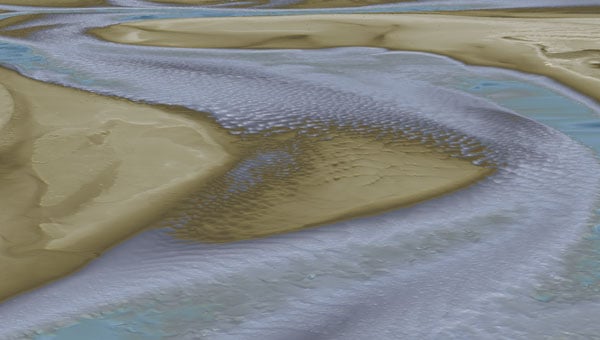
Sites surveyed include Admiralty Bay, Livingston Island and Deception Island, which includes an active, flooded volcano caldera. The resulting, high-accuracy maps will support further scientific and oceanographic research, environmental monitoring, and improvements to marine charts.
By adding high-accuracy locations with an average accuracy of 10 cm to 20 cm horizontal and vertical, the team was able to accurately georeference and further refine the detail of the bathymetry for their map inside the underwater Deception Island caldera. (Photo: Eos Positioning Systems)
As president-elect of the American Association for Geodetic Surveying (AAGS), I participated in a joint quarterly meeting with the National Geodetic Survey (NGS), the National Society of Professional Surveyors (NSPS) and AAGS on April 25.
I invite you to visit the AAGS website and consider joining our monthly board meetings, which are held on the second Tuesday of each month. All are welcome to attend. If you are interested, email me at [email protected] to be added to the attendee list.
Now, for some updates from the joint quarterly meeting.
During the meeting, I provided an update on the Certificate for Geodetic Surveying program, which has been under development by AAGS and is expected to be available by the end of the year. The program is designed to meet the needs of surveyors and others that perform spatial analyses and computations using geodetic methods.
Tim Burch, executive director of the National Society of NSPS, wrote the following in an April 23, 2025, xyHt article:
“To the average professional surveyor, the term “geodesy” does not exist in their everyday conversations about the business. While the use of state plane coordinates has expanded greatly with the development of GPS/GNSS receivers and RTK/RTN connectivity, the mathematics and “black magic” of geodesy remains an enigma to most of the profession.
However, the ongoing progression of technology within surveying instruments has expanded the need for understanding how geodesy works. Our practitioners are faced with expanding their knowledge and expertise of geodesy and thus have put a new challenge on them to find teachers and/or mentors to provide training on the datums and techniques.”
This is exactly what AAGS is attempting to do with the Certificate for Geodetic Surveying program. The information below includes the program description and content. AAGS has developed a set of questions that will determine if an individual has demonstrated a minimum competence in understanding and applying geodetic surveying concepts. AAGS is working with NSPS, who will be administrating the program for AAGS. The status and updates of this program are provided at the AAGS Monthly Board meetings. Come join us to hear more about the program and other AAGS activities.
Certification for Geodetic Surveying
Program description and content. Certification for Geodetic Surveying is official recognition that a person has demonstrated to the satisfaction of the Certification for Geodetic Surveying Board that he or she is minimally competent to perform spatial analyses and computations using geodetic methods. It is not intended to certify scientists performing research in geodesy. Rather, it is for individuals who use geodetic concepts and techniques to solve practical problems as a part of performing their work. Typical practitioners include geodetic surveyors, geodetic/geomatics engineers, geospatial software developers, geographic information systems (GIS) professionals, and geospatial data managers. The focus is more on the use of applied geodetic methods than with a particular field. A person who has obtained the Certification for Geodetic Surveying is one who has demonstrated minimum competence. In this context, “minimum competence” is a combination of working knowledge and familiarity with geodetic concepts that shows the ability to understand and solve applied practical geodetic problems as normally encountered in modern geospatial practice. Importantly, this includes an understanding of one’s limitations in solving such problems.
The Certification for Geodetic Surveying Board will identify the depth of knowledge required to achieve minimum competence for Geodetic Certification in the following areas:
Geometric geodesy
Reference frames, reference systems, geometric datums, and realization strategies
Characteristics of modern reference systems, including NAD 83, WGS 84, ITRF, and IGS
Transformations between datums, both modern and historic
Geodetic, projected, and local geodetic horizon coordinate systems
Direct and inverse problems for geodesics and map projections
Reference ellipsoids, radii of curvature, and types of geodetic and projected distances
Reductions, conversions, and relationships between coordinate systems
Transformations used to create “localization/calibration” coordinate systems
Physical geodesy
Gravity, “the” geoid, gravimetric and “hybrid” geoid models, physical height systems, deflection of the vertical
Vertical geodetic datum definitions and transformations
Types of heights and their relationships; conversions between the various types
Terrestrial methods for vertical, horizontal, and 3-D positioning
Geodetic leveling and height determination; leveling instrumentation and corrections
Modern 3-D terrestrial methods and instruments, including total stations and scanners
Familiarity with historical methods such as triangulation, trilateration, and geodetic astronomy
Accuracy and error
Positional error estimation and uncertainty propagation; statistics and probability theory
Characterization using network and local accuracies, error ellipses, and confidence levels
Temporal aspects
Plate tectonics (both steady-state and episodic); plate-fixed versus no-net rotation reference systems; subsidence; isostatic adjustment; tidal deformation
Time-dependent transformations between reference systems
Global Navigation Satellite Systems (GNSS)
Instrumentation; system architecture; signal structure; error budget
Methods for position determination, including by pseudorange, differential correction, carrier-phase differencing, and precise point positioning
Geodetic survey networks
Design, adjustment, and analysis of GNSS and terrestrial geodetic survey networks
Formulation and solution of least-squares network adjustments
Standards and guidelines
Official standards, specifications, and guidelines for geodetic control, positioning, and accuracy
The US National Spatial Reference System and similar systems elsewhere
Many of you are probably aware of the actions taken by the current administration to reduce the size of the U.S. federal workforce, these actions may affect all users of U.S. geospatial products and services. NGS is not exempt from these actions; recently, they have lost many employees either though leaving service voluntarily, retiring earlier than planned, or having been terminated because they were still in the probation period of their employment. NGS leadership did not provide any details on changes in personnel; only time will tell what the loss of personnel will have with the agency in the future. That said, NGS’s plans still include transitioning the modernized NSRS Alpha Site to a Beta Site this year. The current alpha site has four products — State Plane Coordinate System. SPCS2022, NGS Coordinate Conversion and Transformation Tool (NCAT), Euler Pole Parameters (EPPs) and The North American-Pacific Geopotential Datum of 2022. My understanding is that all four of these alpha products will be transitioned to beta products sometime in 2025. Some may have limited options in the beginning.
During this period, the beta site will provide the content, format and structure of data and products that should not change much from the final product. There could be minor changes detected during the beta phase, but users should not anticipate large significant changes. That said, that is why you have a beta phase before production. It is important for users to access the beta products and identify any issues or concerns and provide feedback to NGS. Future newsletters will highlight the beta products as they are released.
NGS Alpha Site (Photo: NGS website)
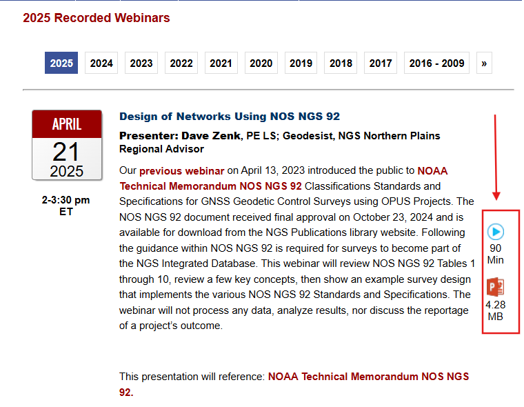
Finally, I would like to highlight a NGS webinar held on April 25, “Design of Networks Using NOS NGS 92.” Dave Zenk, NGS Northern Plains Regional Advisory, gave a good presentation outlining the tables that users need to be familiar with using OPUS Projects to process and submit GNSS projects to NGS for publications. The webinar provided a few examples to explain the concepts. Users can download the webinar from NGS webinar website.
Design of networks using NOS NGS 92. (Photo: NGS website)
I found the webinar to be very informative, and I would encourage all users of OPUS Projects to download the presentation. During the webinar, Dave briefly mentioned three items that I believe deserve more explanation for anyone using OPUS Project. I will address the following topics in more detail in future newsletters:
The mark’s classification — primary, secondary, and local – will not be included on the NGS datasheet but the local and network accuracy from the project will be provided on the datasheet. What does this mean to someone that’s using the mark in their project?
OPUS Project uses the F statistic test to determine if the appropriate constraints were imposed during the horizontally and vertically constrained adjustments. Why does OPUS Project use this statistic?
The Constraint Ratio (CR) test computed by OPUS Projects provides a way of identifying which coordinates should be constrained and which should not be considered for constraints in the final horizontally and vertically constrained adjustments. What’s the best way to use this table?
Again, I would like to invite you to check out the AAGS website and consider participating in AAGS monthly Board meetings. If you are interested in attending the meeting, send an email to me at [email protected].
Finally, users should continue to check NGS’s website for the announcement of the transition from the alpha site to the beta site. Future newsletters will highlight the beta products as they are released.
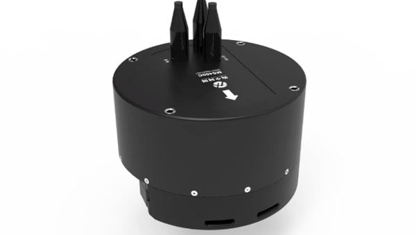
Hydro-Tech has unveiled the MS400C, a fully integrated multibeam echosounder designed for uncrewed surface vessels. The new system combines sonar processing, inertial navigation, GNSS positioning and sound velocity sensing into a single unit.
The MS400C seeks to address deployment challenges faced by USV operators during hydrographic surveying. Its compact, lightweight design allows direct mounting on small platforms. Installation involves connecting a few cables to the IPC and power supply and to the primary and secondary GNSS antennas. With preconfigured spatial relationships, operators can deploy and start surveying quickly, reducing configuration errors and ensuring consistent data quality. Equipped with Auto Survey functionality, the system calibrates parameters based on water conditions, which streamlines pre-survey procedures. Real-time roll compensation and attitude data from the internal IMU, combined with sound velocity profiling, ensure high-fidelity depth measurements, even in dynamic conditions. Designed for autonomous and remotely operated survey platforms, the MS400C supports data collection in confined waterways.
NV5 is celebrating two decades of delivering critical geospatial services to the National Oceanic and Atmospheric Administration (NOAA).
For the past 20 years, NV5 has completed more than 220 contracts across 30 states, covering more than 50,000 square miles. These projects involve topobathymetric surface modeling of shorelines, bays, estuaries, lakes, wetlands, rivers and streams to provide detailed data for various applications. The information generated helps NOAA protect and restore natural resources and habitats, update nautical charts and understand the effects of environmental and human-induced changes over time.
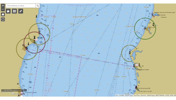
A screenshot from the NOAA ENC Viewer of the updated nautical chart of southern Lake Michigan, created using multibeam bathymetry and backscatter data. (Photo: NOAA)
The company employs airborne remote sensing technologies, such as topobathymetric laser scanning, to capture near real-time changes in nearshore topography and bathymetry. Additionally, NV5 integrates marine vessel-based technologies, such as multibeam echo sounding, to map offshore bathymetry, including sand resources, essential fish habitats and historic shipwrecks.
“Our collaborations with NOAA over the past 20 years have yielded many important insights and baseline data that helps the agency with its core mission of climate monitoring, coastal restoration and supporting marine commerce – all of which supports our nation’s economic vitality and affects more than one-third of America’s gross domestic product,” Dave Bernstein, vice president of hydrospatial operations at NV5, said.
The National Geodetic Survey Remote Sensing Division’s Coastal Mapping Program requires the collection of airborne topographic/bathymetric lidar and digital camera imagery data to enable accurate and consistent measurement of the national shoreline following Hurricane Sandy’s landfall. (Photo: NV5)
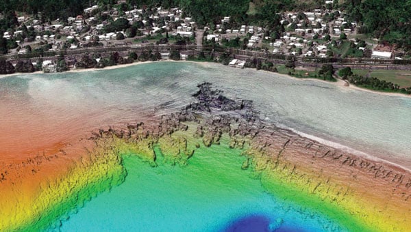
In one notable project, NV5 conducted a large-scale hydrographic survey in southern Lake Michigan for NOAA’s Office of Coast Survey. The survey covered 481 square nautical miles from northeast Chicago to Michigan City, Indiana — an area that had not been surveyed since the late 1940s. Using multibeam bathymetry and backscatter data, NV5 updated NOAA nautical charting products to improve maritime safety along the Michigan, Indiana and Illinois shorelines. Under NOAA’s Office for Coastal Management contract, NV5 also provided certified hydrographer expertise aboard the Pisces (R226), a NOAA fisheries research vessel. These efforts included overseeing the collection and processing of hydrographic data for marine habitat mapping.
A view looking south at the Submarine Canyon on Asan Point, Guam. The image was created from the lidar bare earth model and lidar point cloud colored by elevation and RGB values from imagery respectively. (Photo: Partnership between NV5 and Woolpert)
NV5 has also contributed to NOAA’s Coastal Change Analysis Program through projects that utilized aerial multispectral imagery and machine learning techniques. In Rhode Island, NV5 partnered with the National Estuarine Research Reserve System to study salt marsh habitats and produce change mapping products.
A view looking northeast from Virginia Key shows the topobathymetric surface of the intertidal zone near Fisher Island, Florida. (Photo: Nicholas Klein / iStock / Getty Images Plus / Getty Images)
Similarly, high-resolution land cover products were created for Brown County, Wisconsin, and key watersheds to assess urban growth, map wetlands, delineate wildlife habitats and monitor land cover changes over time. Other initiatives include mapping eelgrass habitats along coastal Massachusetts using multispectral aerial imagery and analyzing satellite imagery for wetland changes in the Great Lakes region.
Through these diverse projects, NV5 continues to provide NOAA with essential geospatial data that supports its mission of environmental stewardship and maritime safety while contributing to national economic vitality.
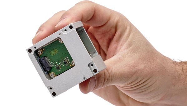
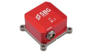
SBG Systems has unveiled its MEMS-based North-seeking inertial measurement unit (IMU) that operates independently of GNSS. According to the company, this launch lays the foundation for future products, such as attitude and heading reference systems (AHRS) and inertial navigation systems (INS), broadening the scope of MEMS-based navigation solutions.
The MEMS-based IMU can achieve a heading accuracy greater than 1° secant latitude without GNSS assistance. When integrated with GNSS and SBG Systems’ navigation algorithms, it can achieve INS heading accuracy greater than 0.01°.
The device features a true MEMS-based design with no moving parts, eliminating the need for carouseling mechanisms. This ensures enhanced durability and reliability across a wide range of operating environments.
Key features of this IMU include its compact size, low weight and minimal power consumption. Measuring 52 x 52 x 36 mm and weighing less than 150 g, it consumes only 2 watts of power. Designed for high-volume production, the device is well-suited for widespread adoption across industries. Additionally, its robust design offers long-term reliability in demanding conditions, and its ITAR-free status allows unrestricted global deployment.
SBG Systems has also developed new algorithms to enhance gyrocompass and INS alignment performance. These include a pure north-finding algorithm capable of rapid initialization in both static and dynamic conditions within one minute, as well as an advanced GNSS/INS fusion algorithm that delivers exceptional single-antenna heading accuracy even in low-dynamic environments.
It can be used for applications such as marine operations, autonomous systems and georeferencing. The IMU is particularly suited for subsea applications including remotely operated vehicles and autonomous underwater vehicles, as well as geospatial and marine surveying tasks requiring precise single-antenna heading accuracy.
The first off-the-shelf solutions are expected to be available by early 2026.
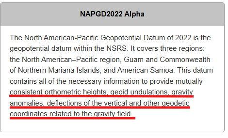
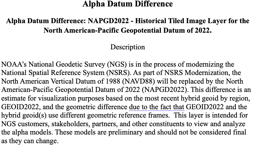
My January 2025 GPS World newsletter mentioned that the National Geodetic Survey (NGS) made several updates to the North American-Pacific Geopotential Datum of 2022 (NAPGD2022) products and that these updates are now available on the NGS alpha site. NGS held a webinar on Jan. 9, 2025, to discuss NAPGD2022 and explain the product updates. I highlighted the NGS Alpha site and GEOID2022 — a product of the NAPGD2022 — in my July 2024 newsletter.
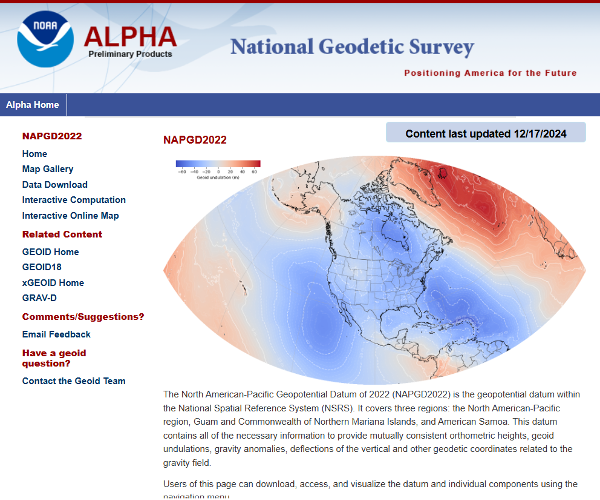
This newsletter will highlight the NAPGD2022 alpha site and the components on the Alpha site — GEOID2022, DEFLEC2022, DEM2022 and GRAV2022. See below for a description of the site.
NGS users of the new National Spatial Reference System (NSRS) should determine the impact on their products and services. For example, the effect of using NAPGD2022 orthometric heights instead of the North American Vertical Datum of 1988 (NAVD 88) on flood plain maps and FEMA elevation certificates.
I have experience dealing with the impact of products and services changing from one national vertical datum to another. When I worked for NGS, I was the Project Manager of NAVD 88. The adjusted heights from the NAVD 88 general adjustment were officially published on June 15, 1991. Performing the adjustment of NAVD 88 was a relatively simple task compared to implementing of NAVD 88 in geospatial products and services in the United States. I wrote articles and talked about the change in the datum from the National Geodetic Vertical Datum of 1929 (NGVD 29) to NAVD 88 at surveying and mapping conferences several times a year during the decade before the completion of the adjustment. Many users were still surprised by the change and the impact on their products and services. It’s a little different today because there are more ways of getting the word out in today’s digital world, such as webinars, Zoom meetings and digital magazines. That said, users still need to participate in webinars and Zoom meetings and read digital articles to understand the changes to geospatial products and services.
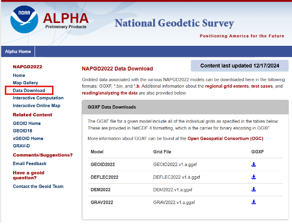
Users can download gridded files of the models to create their own routines to analyze the models in their region.
Photo: NGS
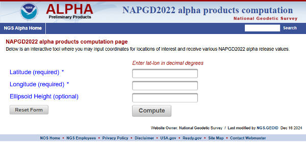
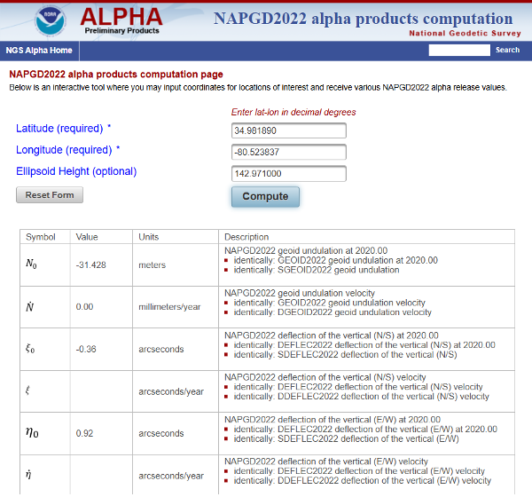
The site provides an option for users to perform single point interactive computations.
Single point interactive computations. (Photo: NGS)
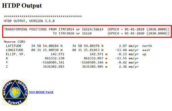
The differences between the ITRF 2014 (epoch 2010.0) coordinate and ITRF 2020 (epoch 2020.0) in North Carolina are not very large. Still, I used NGS’s HTDP tool to transform the North Carolina Monroe CORS (NCMR) ITRF 2014 (epoch 2010.0) coordinates to ITRF 2020 (epoch 2020.0) and then entered the transformed values into the interactive tool. See the images “HTDP Output for NCMR” and “Interactive Computation Page” for an example of the output of the single-point interactive computation tool.
HTDP output for NCMR. (Photo: NGS) Photo: NGS
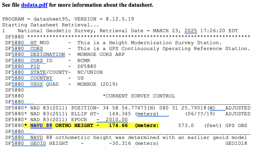
I have highlighted the NAPGD2022 orthometric and dynamic heights for NCMR CORS. I downloaded the latest NGS datasheet for the North Carolina Monroe CORS (NCMR) to obtain the published NAVD 88 height. See the image below.
NGS data sheet for Manroe CORS. (Photo: NGS)
In my example, the difference between the NAPGD2022 and NAVD 88 orthometric height is -0.26 meters (174.40 m – 174.66 m). It should be noted that the tool also provides a dynamic height for the mark. Dynamic heights are used by the International Great Lakes Datum (IGLD). My August 2021 GPS World Newsletter provides more information on the update to the IGLD 85 and dynamic heights. The interactive computation page tool also provides the GEOD2022 value for the mark. The difference between GEOID2022 and GEOID18 for the mark is -0.112 meters (-31.428 minus -30.316).
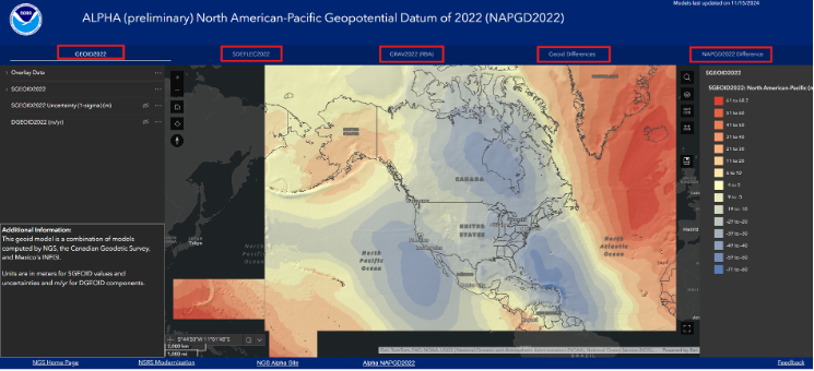
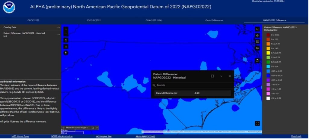
The alpha site provides an option to use an interactive online map that allows users to access GIS maps that depict individual models. I have highlighted the five layers on the box titled “NAPGD2022 Interactive Online Map” – GEOID2022, SDEFLEC2022, GRAV2022 (RBA), Geoid Differences, and NAPGD2022 Differences.
To demonstrate the online maps, I clicked on the layer titled “NAPGD2022 Difference” located in the upper right corner of the of the map. The image below provides a description of the layer.
Photo: NGS
Users can click on the map, and the pop-up provides information about the location. In the example below, the popup provides the difference between the NAPGD2022 orthometric height and the NAVD 88 height.
The difference between NAPGD2022 orthometric height and NAVD 88 height. (Photo: NGS)
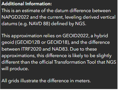
Additional information about a layer is provided on the lower left side of the map page.
Additional information for NAPGD2022 difference. (Photo: NGS)
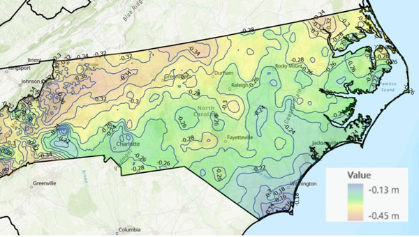
NGS’ online maps didn’t depict the details I wanted to visualize, so I downloaded the data and created my own maps.
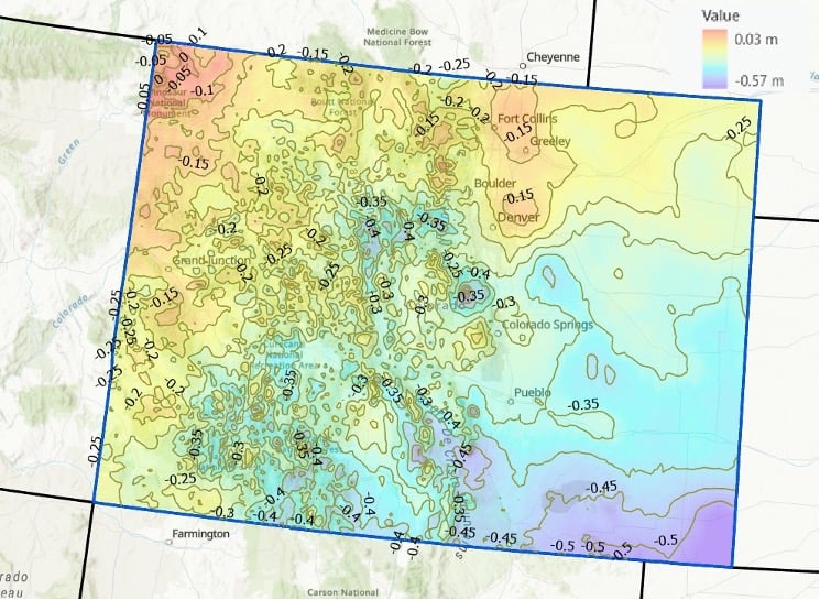
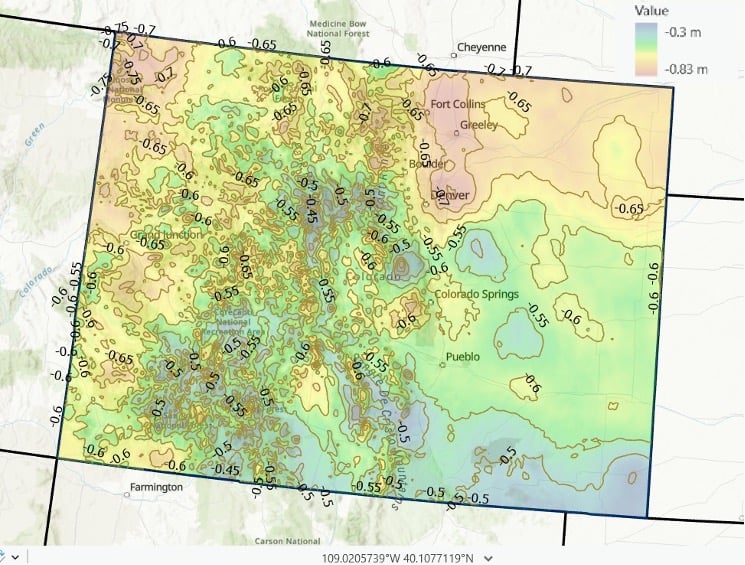
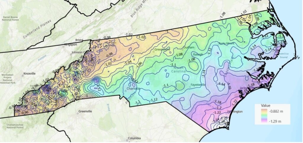
I provided a couple of examples of the differences between NAPGD2022 and NAVD 88 below: one for North Carolina and one for Colorado. As you can see from the plots, there are significant relative differences in mountainous regions (western North Carolina and western Colorado), and a lot of local variation across the state.
Differences between NAPGD 2022 orthometric heights and NAVD 88 in North Carolina (2 cm contour intervals). (Photo: Dave Zilkoski) Differences between NAPGD 2022 orthometric heights and NAVD 88 in Colorado (5 cm contour intervals). (Photo: Dave Zilkoski)
I used the same process to determine the differences between GEOID2022 and GEOID18. See the images titled “Differences between GEOID2022 and GEOID18 in North Carolina” and “Differences between GEOID 2022 and GEOID 18 in Colorado.” Again, it should be noted that there is a lot of variation across the state.
Differences between GEOID2022 and GEOID18 in North Carolina (2 cm contour intervals). (Photo: Dave Zilkoski) Differences between GEOID 2022 and GEOID 18 in Colorado (5 cm contour intervals). (Photo: Dave Zilkoski)
In summary, in a few months, NGS will be releasing a Beta version of the new terrestrial reference frames and geopotential datum. This newsletter highlighted the NAPGD2022 alpha site and the components on the Alpha site — GEOID2022, DEFLEC2022, DEM2022, and GRAV2022. I did a 4-part series in my GPS World newsletters in 2017 on the products of NAPGD2022 (June 2017, August 2017, October 2017 and December 2017).
Unicore has introduced the UM981 series, a high-precision positioning module that integrates RTK and inertial navigation system (INS) technologies. The solution leverages GNSS and INS navigation to cater to applications in precision agriculture, surveying and mapping.
The module is compatible with all major navigation systems and frequencies, tracking signals from multiple systems simultaneously for enhanced performance even in challenging environments. Additionally, the UM981 series supports open Precise Point Positioning (PPP) services such as BDS-3 PPP-B2b, Galileo E6 HAS and QZSS L6 MADOCA-PPP, achieving 10 cm positioning accuracy with a convergence time of under 10 minutes, according to Unicore.
The UM981 series processes high-frequency GNSS and IMU data streams efficiently, offering RTCM data transmission at up to 20 Hz, single-point positioning and RTK at up to 50 Hz and integrated navigation data and IMU raw data at up to 100 Hz. These capabilities make it suitable for dynamic scenarios requiring high precision.
In precision agriculture, the UM981 module simplifies machinery auto-steering systems by enabling single-antenna positioning and attitude determination through advanced MEMS technology. At speeds above 1 km/h, it achieves heading accuracy better than 0.3° and roll/pitch measurements better than 0.2°, with accuracy improving as speed increases. The module supports CAN Bus communication and can be customized to work with the ISOBUS Protocol, eliminating the need for switching between interfaces during serial port communication.
For surveying and mapping applications, the UM981S variant delivers high-accuracy positioning and tilt measurement using GNSS and INS fusion algorithms. It eliminates traditional shake-to-start requirements with a walk-and-go feature that allows users to initialize tilt measurement simply by walking with the measurement pole. The module provides 2.5 cm accuracy within a 30° tilt range and supports measurements at larger angles up to 120°, making it suitable for complex environments such as building corners or areas under tree canopies.
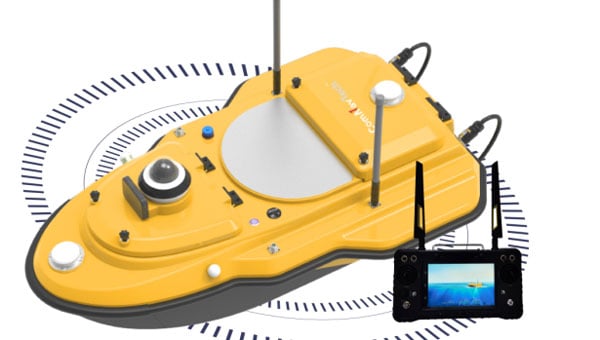
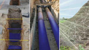
ComNav Technology has released the SV600 unmanned surface vessel (USV) for hydrographic surveying. This remote-controlled vessel incorporates adaptive water-flow straight-line and hovering technology, enhancing efficiency and ease of operation.
A key feature of the SV600 is its dual-moon pool design, which allows for simultaneous deployment of various surveying equipment. This includes Acoustic Doppler current profilers, single-beam echo sounders, side-scan sonar, pipeline detectors and miniaturized multi-beam echo sounders.
The vessel’s design prioritizes versatility and quick transitions between tasks. Its rapid installation feature facilitates seamless switching between different measurement modes, streamlining the surveying process, according to ComNav.
ComNav Technology has revealed the LS600, a handheld 3D laser scanner that integrates SLAM technology, a built-in RTK module and dual 16MP wide-angle cameras. The device employs multi-sensor fusion, including lidar, IMU and cameras, to deliver high performance in both indoor and outdoor environments. It offers 16- or 32-line lidar options, with a scanning range of up to 300 m and a speed of 640,000 points per second for rapid data collection.
The LS600 features an advanced GNSS module that provides centimeter-level accuracy with full-frequency GNSS support. A built-in surveying antenna enhances signal reliability. The dual-lens camera, combined with visual SLAM (V-SLAM), produces detailed color point clouds for realistic and precise visuals. The scanner supports both backpack and pole configurations, making it versatile for applications such as land surveying, engineering, urban renewal, mining, agriculture, forestry and emergency response.
Its automated post-processing capabilities — such as stitching, denoising, and rendering — along with flexible coordinate systems streamline workflows and ensure accurate results. This design allows professionals to achieve precision and efficiency in the field.
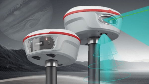
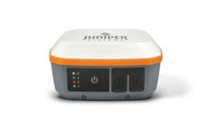
ComNav Technology has introduced the Jupiter Laser RTK, which is designed for surveying and stakeout operations. The system offers a range of up to 50 m with centimeter-level accuracy and eliminates the need for traditional poles for efficient performance in routine and complex environments.
Equipped with a global night vision camera and laser technology, the Jupiter Laser RTK maintains high efficiency even in low-light or nighttime conditions. Its laser remains visible in the dark, enhancing usability during survey and stakeout tasks. The system also features visualized capabilities through a handheld data collector with an intuitive interface. Users can easily view point positions and follow directional arrows and real-time distances via Survey Master software’s 3D visual interface to accurately mark stakeout points.
The dual-camera system further enhances precision by guiding stakeout paths with a front camera for long-distance views and switching to a bottom camera for close-range detail. A flashing laser replaces traditional walkie-talkies near stakeout points, while visualization compensates for the laser’s invisibility in bright light or over long distances. These features improve efficiency by up to 30%.
Jupiter Laser RTK incorporates cutting-edge technologies such as the K8 board, which tracks up to 1,668 channels across all satellite constellations for reliable positioning. Its Super Datalink supports a 15 km working range and full-protocol compatibility, while Auto IMU provides tilt compensation up to 120° without manual initialization. Designed for durability, the system is waterproof, drop-resistant, and equipped with long battery life, ensuring reliable performance in diverse environments.
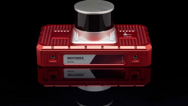
OxTS has released WayFinder, a new localization solution designed for use in GNSS-denied environments. The system combines a GNSS/INS system, onboard processor, lidar scanner and two cameras to enable accurate positioning in areas with limited satellite coverage, such as urban canyons and underground tunnels.
Precise localization data is crucial for various industries, including autonomous navigation, automotive testing and sensor data georeferencing. However, obtaining accurate positioning information in areas with weak or unavailable GNSS signals has been a persistent challenge. WayFinder is designed to operate with minimal setup, requiring only basic configuration before use. The system’s key feature is Lidar Boost, a new software technology that enhances GNSS/INS performance in environments with unreliable satellite signals.
Lidar Boost employs advanced algorithms to process data from the integrated Lidar scanner, compensating for missing or erroneous GNSS updates in real time. This allows WayFinder to maintain high-accuracy localization in areas with limited satellite coverage and ensure smooth transitions between GNSS-supported and GNSS-denied environments.
The system can be used across multiple sectors. In ports, it can provide precise localization for autonomous vehicles operating among stacked shipping containers. In mining, it can support navigation for both underground and surface vehicles. WayFinder also offers a solution for indoor automotive testing without the need for fixed infrastructure. Surveyors working in areas with intermittent GNSS coverage can also benefit from its positioning capabilities.
Read a roundup of recent products in the GNSS and inertial positioning industry from the March 2025 issue of GPS World magazine.
Surveying and Mapping
Photo: Eos Positioning Systems
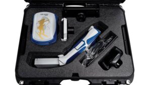
New Eco-Friendly Carrying Case For Eos Positioning Systems’ receivers
The Skadi Gold, Skadi 300 and Skadi 200 GNSS receivers will now be shipped in a field-rugged carrying case made entirely from recycled materials. The case is designed to meet the demands of professionals who utilize GNSS technology in challenging environments. Its construction incorporates durable, eco-friendly materials that can withstand various field conditions, from remote wilderness areas to urban construction sites.
A key feature is its composition of 100% post-consumer recycled resin, which significantly reduces waste and promotes environmental sustainability, according to the company. It is specifically engineered to be shock-resistant and weatherproof.The case is provided as a standard inclusion with every purchase of the Skadi Gold, Skadi 300 or Skadi 200 GNSS receivers at no additional cost.
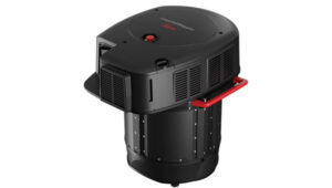
Multibeam Sonar Designed for bathymetric surveying
The Gemini 1200id is built on the same robust platform as the Gemini 720is multibeam sonar. The device features a 120° horizontal field of view, operating at both 720 kHz and 1,200 kHz acoustic frequencies.
The Gemini 1200id incorporates advanced noise reduction technology to significantly improve the attenuation of waterborne electrical noise to enhance imaging performance. An integrated speed-of-sound sensor ensures high positional accuracy of displayed targets, while CHIRP processing technology enhances target separation over extended ranges.
Compatibility with Tritech’s Genesis software package allows users to control multiple Tritech products from a single interface to streamline operations. The company has also made software development kits available for Windows and Linux operating systems to integrate into various platforms. The sonar’s design includes a custom-developed analog front-end solution with fully differential receiver channels, making it ideal for longer-range applications.
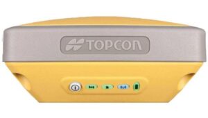
HiPer XRa is a GNSS receiver for surveying, mapping and construction applications. It can benefit a wide variety of users, including construction professionals, surveyors, geographic information systems (GIS) professionals, archeologists, engineering firms and more. The HiPer XR supports GPS, GLONASS, Galileo, BeiDou, IRNSS, QZSS and SBAS.
The new receiver has advanced Topcon Integrated Leveling Technology (TILT) compensation, featuring a calibration-free and magnetic interference-immune integrated IMU that provides up to 60° of tilt for precision measurements in challenging positions. It has signal integrity protection, anti-jamming and anti-spoofing capabilities. Through the myTopcon NOW! website, users can access online training materials, firmware updates and additional software resources.
Airborne Lidar System Ideal for coastline and river surveying
CoastalMapper is an airborne bathymetric lidar system for coastline and river surveying. The CoastalMapper can survey coastlines and rivers 250% faster than previous sensor models, according to Leica Geosystems.
It is suitable for various mapping applications, from assessing infrastructure resilience to monitoring river floods and conducting environmental investigations.
It features a high-performance bathymetric lidar module, a Leica TerrainMapper-3 topographic lidar and an imaging sensor, integrated into a compact and lightweight sensor head. This allows the CoastalMapper to capture up to 1 million bathymetric data points and 2 million topographic data points per second while providing high-resolution imagery with a 5-cm ground sampling distance at typical flying heights.
It integrates with Leica Geosystems’ airborne mapping workflows and offers cluster processing capabilities, allowing users to analyze large datasets and reduce the time from data collection to final deliverables. These outputs can include classified point clouds, digital terrain and surface models, and various imaging products.
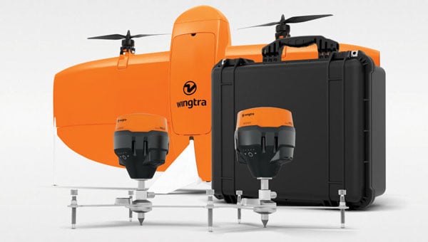
Surveying Kit Streamlines base station and checkpoint setup
WingtraGROUND, a comprehensive survey kit, streamlines base station and checkpoint setup for on-site post-processing kinematic surveys with the WingtraONE Gen II, a vertical takeoff and landing UAV. The kit combines receivers, checkpoints and tools into a single, portable workflow.
The system integrates hardware components with a Wingtra tablet interface, which can help surveyors confirm correct receiver placement and avoid common errors associated with improper base station setup and inaccurate coordinates.
Wingtra receivers, equipped with Emlid Reach RS3 technology, provide accuracy within 2 cm, meeting high standards for aerial data validation. These receivers can also function independently for terrestrial surveys in real-time kinematic mode, including point collection and stakeout for various applications.
Galileo HAS-Enabled Receiver Offers positioning capabilities with 20 cm accuracy
The Geode GNS3H supports Galileo High Accuracy Service (HAS). It offers positioning capabilities with 20 cm accuracy worldwide without requiring additional infrastructure or subscriptions.
It is built to withstand tough conditions, making it ideal for demanding fieldwork. The device offers various accessories, including the Geode Grip, which combines the Geode with a data collection device of choice into a single handheld solution. A backpack strap kit and survey pole are also available to enhance mobility and flexibility in the field. The GNS3H can be used for surveying, agriculture, construction, forestry, mining and archaeology.
Expanded Mapping Portfolio 3D mapping technologies and more
Topcon Positioning Systems has become an authorized distributor of Pix4D’s photogrammetry software portfolio.
The partnership aims to enhance reality capture solutions across various industries, including surveying, mapping, utilities infrastructure, public safety, forensics, and architecture, engineering and construction.
The agreement streamlines the procurement process for end users by allowing them to access Pix4D’s advanced photogrammetry software solutions through Topcon’s global distribution network.
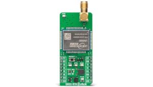
The GNSS real-time kinematic (RTK) 5 Click — a compact add-on board for high-precision positioning and navigation demands — features the UM980, an all-constellation multifrequency RTK positioning module from Unicore, with the advanced NebulasIV SoC for enhanced performance.
It supports Swift Navigation’s Skylark precise positioning service, multiple GNSS constellations and RTK positioning for centimeter-level accuracy. The board also features JamShield technology for robust performance in challenging environments, USB connectivity for easy configuration and visual status indicators for module status and GNSS signal reception.
It can be used for a variety of applications, including surveying and mapping, precision agriculture, UAVs, autonomous robots and autonomous driving.
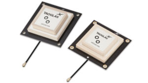
Multi-Band GNSS Antenna Can operate in urban environments
Levity Series’ AHP24510 (L1/L2/L-Band) and AHP54510 (L1/L5/L-Band) directional patch antennas are designed to receive signals from GPS, Galileo, GLONASS and BeiDou satellite constellations.
These antennas offer faster and more accurate signal acquisition and lock, specifically in urban environments. The L-Band capability allows compatibility with high-precision GNSS correction services. The multi-band antennas offer integral redundancy to minimize satellite security blind spots and reduce energy consumption due to faster acquisition, requiring less system uptime to save power.
The Levity Series active antennas feature a 45 mm x 45 mm x 10 mm wide-band, dual-stacked patch design with a dual-feed, low noise amplifier, providing 28 dB to 29 dB gain and filtering. They operate with a maximum antenna VSWR of 1-to-1 from 1,207 MHz to 1,603 MHz, and the passive antenna efficiency ranges from 39.93% to 68.51% in the L1 band. These antennas use right-hand circular polarization to mitigate multi-path interference.
The Levity Series includes other multi-band products for high-precision applications, such as the HP24510A and HP54510A stacked-patch passive components, and the TFM.120A surface-mount front-end module, which covers the full multi-band GNSS spectrum including L-band. These antennas are suitable for various applications, including wearables, transportation, robotics, precision agriculture and autonomous vehicles.
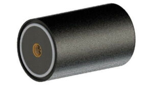
The M9PLUS-HCT-A-SMA is an active multi-frequency GNSS antenna designed for high-accuracy applications. It supports L1/L2/L5 GPS, Galileo, Beidou and GLONASS bands, as well as L-band correction services. The antenna utilizes Maxtena’s proprietary Helicore technology, which offers advanced pattern control, polarization purity and efficiency in a compact form factor.
It integrates a pre-filter specifically engineered to mitigate LTE interference. This is crucial for maintaining signal integrity in environments with dense mobile communication networks, where LTE signals can overlap with GNSS frequencies. The pre-filter can effectively block out-of-band LTE signals, reducing intermodulation risks and ensuring clear GNSS signal reception.
The M9PLUS-HCT-A-SMA is built with rugged, IP67 automotive-grade components and includes an integrated SMA connector. It also features an O-ring for enhanced environmental sealing. Weighing only 24 grams, the antenna is ground plane-independent, making it versatile for various installations. It is particularly well-suited for GIS and RTK applications where high accuracy and reliability are crucial.
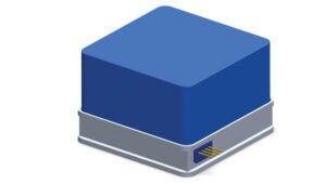
The MostaTech G321M is a three-axis fiber optic gyroscope (FOG) that offers high-precision navigation and orientation measurement capabilities. This advanced sensor features a data rate of 8 kHz.
Key features of the G321M include an input range of 400° per second, a bias RMS of 1° per hour and an angular random walk of 0.025 °/√h. Additionally, it has a power consumption of 2 W and an initialization time of 1 second. The G321M is designed with a compact form factor, making it suitable for various applications where size and weight are critical factors.
It is ideal for UAVs, robotics, borehole surveys, image stabilization, gimbal stabilization and underwater vehicles.
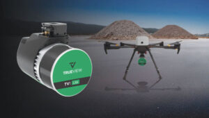
High-Precision Lidar Designed for precision applications
The TV1 Lite and the TV1 UAV systems are designed for various precision applications, such as mapping and data collection.
The TV1 Lite features TrueNav technology, a Hesai 32-channel laser scanner and a FLIR 5MP global shutter camera with a 90° field of view. It also includes one year of TV1 Lite Annual Processing with support and maintenance.
TV1 offers customization options, allowing users to choose from 26 MP, 45 MP or 61 MP cameras and various Trajectory Correction Service options.
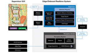
Flight Control System With autopilot functionality
The Prism Supervisor software combines UAV autopilot flight control systems with AI-based observations processed in real time, aiming to enhance UAV operations.
The system provides a programming framework and software development kit for users to create custom mission scenarios. During flight, Prism Supervisor can adapt its autopilot functionality in real time, generating mission segments and flight plans as needed.
The software features a user-friendly graphic interface for mission planning, real-time visualization and execution. It supports Windows, Linux, macOS, iOS and Android.
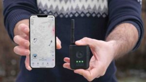
Remote ID Receiver Enhances airspace awareness and UAV safety
RIDER is designed to enhance situational awareness by providing real-time detection of UAV activity in sensitive areas. It also seeks to provide a clear visibility of surrounding UAV operations to help avoid potential collisions and ensure safer flight experiences.
The device features a built-in industrial chip SIM that provides global coverage through LTE-M and NB-IoT, ensuring connectivity in various environments.
It operates effectively within a temperature range of -20 °C to +60 °C and is rated IP54 for dust and water resistance. The device complies with ASTM F3411-22A and ASD-STAN EN 4709-002 standards, making it suitable for regulatory environments.
The RIDER can detect signals from up to 5 km with its default antennas and up to 10 km when using an optional high-performance antenna. It is equipped with an internal cellular and Bluetooth antenna, along with an integrated GNSS antenna that provides precise positioning and timestamping capabilities. It supports multiple GNSS frequencies and utilizes Bluetooth and Wi-Fi technologies for Remote ID communications.
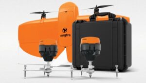
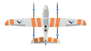
Streamlined BVLOS Operations For a variety of applications
The Sentaero 6 UAV is designed for advanced over-the-horizon operations beyond visual line of sight (OTH-BVLOS). It features built-in AI and machine learning capabilities for real-time data processing. The system can be used for surveying, mapping, inspection, asset monitoring and more.
Engineered to streamline operations, the Sentaero 6 offers more accurate and up-to-date intelligence on assets. Its onboard computer can processes data mid-flight.
Future developments will include swarm operations, enabling one human to control multiple UAVs simultaneously; fully remote operations and higher safety standards, such as a parachute for urban missions, according to Censys Technologies.
SBG Systems has significantly updated its Ellipse series sensors, incorporating the latest World Magnetic Model (WMM) to enhance accuracy and reliability in navigation applications. This upgrade is available for all Ellipse sensors, including first-generation models.
Designed for unmanned systems such as UAVs, UGVs and marine platforms, the Ellipse series comprises compact, high-precision inertial sensors. These devices feature built-in three-axis magnetometers that measure Earth’s magnetic field, crucial for accurate heading and positioning data.
Updated every five years, the WMM is a globally recognized mathematical representation of Earth’s magnetic field. The latest version, released in December 2024, ensures precise heading and positioning corrections to account for ongoing geomagnetic changes.
NDAA-Compliant UAV Now integrated with ArcGIS Flight
Esri now supports the Astro Max UAV in its ArcGIS Flight application. The Astro Max is the first Blue UAS-cleared and NDAA-compliant UAV to integrate with Esri’s platform.
The Astro Max, developed by Esri partner Freefly Systems, adheres to the security and performance standards set by the National Defense Authorization Act and the Defense Innovation Unit’s Blue UAS initiative. This industrial UAV is designed to enhance the capabilities of government and enterprise users utilizing ArcGIS Flight.
Autonomous Swarm Control Controls various autonomous platforms
The Autonomous Multi-Domain Operations Resiliency Platform for Heterogeneous Unmanned Swarms (AMORPHOUS) software features a single-user interface to operate thousands of autonomous assets simultaneously. Designed with an open architecture, this software enables the U.S. and allied militaries to control a mix of uncrewed platforms, payloads and systems.
AMORPHOUS includes an intuitive and distributed command-and-control interface to give operators the flexibility to conduct a wider array of intricate military missions. This collaborative autonomy at scale will provide warfighters with a decisive overmatch capability.
L3Harris is developing prototypes using the AMORPHOUS architecture on contracts for the U.S. Army and the Defense Innovation Unit. AMORPHOUS has demonstrated flexibility and interoperability by controlling multiple, separate assets across multiple vehicle types operating in different domains during government-managed tests.
AMORPHOUS supports decentralized decision-making, which enables individual, uncrewed assets to perform tasks autonomously and make real-time tactical decisions inside the network.
Advanced Counter-UAV Radar Multi-console radar control and display system
Cambridge Pixel has developed a radar control and display system for Weibel Scientific’s XENTA surveillance radar, which is designed for modern air defense and counter-unmanned aerial systems (C-UAS) applications.
The XENTA radar includes 3D target tracking, continuous target illumination and synthetic receiver beamforming. It is available in two configurations: the XENTA-M for short-range air defense and the XENTA-C for C-UAS operations.
The system is designed to work seamlessly with third-party command-and-control systems, enhancing operational efficiency.
Cambridge Pixel’s library of radar processing software allows users to develop a tailored radar controller specific to the XENTA radar’s requirements. Enhancements were made to existing functionalities, such as improved MIL-STD-2525 overlay graphics and support for dual-redundant operator consoles.
The XENTA radar system can detect small UAVs at distances exceeding 7 km and classify them beyond 5 km. This capability makes it suitable for various applications, including airport security, border control, critical infrastructure protection and event security.
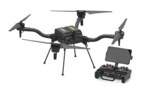
The Pelican 2 agricultural spray UAV has an expanded 300-liter payload capacity and can cover up to 5.3 ha/hr.
It incorporates several technological enhancements designed to meet the demands of agriculture applications. The aircraft features an upgraded four-motor electric propulsion system, a wider 18-m spray swath and advanced lidar and radar systems for fully autonomous day-and-night spraying. These improvements aim to increase efficiency and precision in aerial application while reducing operational costs for farmers.
The Pelican 2’s airframe and structural components are constructed from carbon fiber composites, corrosion-resistant metallic components and 3D-printed assemblies.