Reynolds is director of Inta Communication Ltd. and a long-term Brussels observer writing on many aspects of European government policy and implementation for a range of clients and publications. He is the contributing editor for GPS World’s new quarterly e-newsletter, EAGER: the European GNSS and Earth Observation Report.
The annual summit, held in the historic Munich Residenz, is an conference with global impact dealing with satellite navigation. The one-of-a-kind convention of high-ranking worldwide speakers from industry, science and governments provides the participants with a broad overview and different perspectives on the latest developments in the field of GNSS.
Reynold’s session, GNSS and Sciences for Life, will cover maritime search and rescue (SAR), precision agriculture and livestock management, personal fitness and emergency medical attention.
Other sessions include:
GNSS Program Updates — Global systems, chaired by Hank Skalski, Department of Transportation, DOT Liasion to Air Force Space Command, Peterson Air Force Base, USA
GNSS Program Updates — Regional and augmentation Systems, chaired by Dr. Todd Walter, Stanford University, CA, USA
GNSS in the Southern Hemisphere and Equatorial Regions, chaired by Prof. Vidal Ashkenazi, Chief Executive of U.K.-based Nottingham Scientific Ltd, Nottingham, UK
Precise Positioning Technology in Agriculture and Forestry, chaired by Dr. Herbert Landau, Managing Director, Trimble Terrasat GmbH, Hoehenkirchen, Germany
Legal Issues of GNSS Timing, chaired by Dr. Ingo Baumann and Dr. Oliver Heinrich, Partner, BHO Legal, Cologne, Germany
Plus, expect a brand-new conference format for this session:
The GNSS Knowledge Triangle: Tying the Knot Between Education, Research and Industry, chaired by Dr. Fabio Dovis, Associate Professor, Politecnico di Torino, Turin, Italy
The summit is part of the efforts of the Bavarian government and the cluster on aerospace and satellite navigation to stimulate applications and services in this high-tech field.
Wavelet Packet Decomposition (WPD) shows promise as an anti-jamming tool.
The WPD is derived from the wavelet transform, which provides a representation of the signal components in a domain spanned by a set of functions that can be seen as band-pass filters with a bandwidth decreasing as their central frequency increases, thus granting a uniform resolution in the decomposition of the signal under analysis.
A paper by Luciano Musumeci and Fabio Dovis of Politecnico di Torino and James T. Curran of the Joint European Commission’s Research Center, titled “A Comparative Analysis of Adaptive Notch Filtering and Wavelet Mitigation against Jammers Interference,” won the Best Paper in Session award in GNSS Vulnerabilities and Anti-Jamming at the ION-GNSS+ 2015 conference.
The paper compares two interference mitigation techniques at the digital signal processing level for jamming signal removal.
The authors compare the traditional adaptive notch filtering scheme, widely discussed in scientific literature, with a new technique based on the use of the WPD. Both techniques are implemented in software, and their performance has been assessed via the use of a fully software GNSS receiver. Both techniques are first applied to a set of simulated GNSS jammed scenarios.
Preliminary results demonstrate that a significant improvement is achieved at both acquisition and tracking level when the WPD algorithm is employed with respect to the application of the classical adaptive notch filtering. In fact, using the adaptive notch filtering, the effective range of the jamming can be reduced from approximately 474 meters up to 127 meters, while when using the WPD-based algorithm, such a range can be further reduced up to approximately 10 meters. These results are also confirmed by successive test campaigns where performance comparison of both software implemented techniques is assessed considering simulated GNSS data.
The WPD-based technique is characterized by a higher computational complexity with respect to the implementation of notch filtering. This is mainly caused by the several filtering operations needed for the time-scale representation computation. Therefore, the number of decomposition stages and the filter length need to be carefully traded off with the jamming detection and removal capability of such a technique.
However, the availability of a high-performing processor together with a jamming detection based on spectral estimation can potentially lead to a faster WPD computation for future real-time applications.
Launching at a tower site near Vaughn, New Mexico, Insitu accomplished a commercial beyond-visual-line-of-sight operation with an unmanned aerial system (UAS).
The Oct. 25 event marked the beginning of a week-long series of flights with BNSF Railway designed to show how UAVs can enhance the safety of critical infrastructure by aiding with inspections.
During the 14 hours of flyovers, the Insitu ScanEagle targeted problems such as washouts and bridge damage. The information gathered was then fed back to Insitu personnel on the ground in real time.
Insitu and BNSF officials launch ScanEagle for the historic first flight. (Photo: Insitu Inc.)
The flights were part of the U.S. Federal Aviation Administration’s (FAA’s) Pathfinder program announced on May 6. For Pathfinder, the FAA selected three companies — CNN, PrecisionHawk and BNSF — to explore commercial use of drones beyond operations proposed in its draft UAS rule published in February.
The FAA tasked BNSF Railway, the second-largest freight railroad network in North America, with inspecting rail infrastructure beyond visual line of sight. BNSF operates 32,500 miles of track.
BNSF selected the Scan-Eagle because it carries an FAA certification for commercial applications. The UAV is capable of providing 3D rendering as well as high-resolution video magnification.
In its first day of operations, the ScanEagle UAV provided real-time video covering 64 miles of the 132-mile stretch of track that BNSF has designated for the exercise. The ScanEagle is capable of flying for up to 24 hours at speeds of up to 80 knots.
The exercise demonstrated how, in addition to a railway company’s traditional methods of track monitoring, unmanned aircraft can not only improve inspections, but keep employees out of harm’s way and harsh conditions.
Insitu, a subsidiary of The Boeing Company, creates and supports unmanned systems and software technology for collecting, processing and understanding sensor data.
Under Pathfinder, CNN is researching visual line of sight operations for newsgathering in urban areas, and working with Georgia Tech University to improve newsgathering for all organizations. PrecisionHawk is investigating agricultural operations for rural areas, flying outside line of sight.
MicroSurvey Software has released MicroSurvey CAD 2016, the newest generation of its desktop survey and design program for land surveyors and civil engineers. Powered by a new IntelliCAD 8.1a engine and enhanced with a suite of new point-cloud management tools, the software makes high-impact drafting and design fast and intuitive, the company said.
Users on multi-core computers will experience up to 300 percent faster performance compared to previous versions, which substantially improves productivity. Navigation has been enhanced through a new ribbon interface with high-resolution icons that provide easy access to frequently used tools. The newest version of the software is also able to open and export DGN files, handle annotation scaling, and publish drawings as DWF/DWFX, PNG and JPG files.
Point Clouds. The new release includes significant enhancements for working with point clouds. The Ultimate and Studio versions of the software are now powered by the same point-cloud engine that drives Leica Cyclone and CloudWorx software, making it possible to directly import Leica Cyclone and Leica JetStream databases using Cyclone dialogs.
Users can view panoramic photographs captured by the laser scanner and snap to points directly from the photographs in a TruSpace window. Point-cloud data is now displayed directly within the CAD model space.
MicroSurvey CAD is compatible with field data from all major total stations and data collectors and is fully compatible with AutoCAD; 64-bit and 32-bit versions are available.
Advances in micro-electro-mechanical systems (MEMS) sensor technology include temperature-sensing MEMS oscillators (TSMO). Pairing a TSMO with a GNSS receiver, the authors successfully performed carrier-phase positioning and obtained accuracies better than typically required for automotive applications. MEMS oscillators can present space and cost advantages in integrated circuit assembly. By Bernhard M. Aumayer and Mark G. Petovello
MEMS oscillators have found their way into the electronics industry and are on their way to enter a multi-billion consumer devices market, which is currently dominated by crystal-based oscillators. One technology review concluded that MEMS oscillators fill the gap between high-performance quartz and low-performance LC (inductor+capacitor) oscillators while allowing for better system and package integration.
Nevertheless, due to stringent requirements on frequency accuracy and phase noise, MEMS oscillators have not yet been integrated in GNSS receivers.
In earlier research, we demonstrated the feasibility of using a temperature-sensing MEMS oscillator (TSMO) in a software receiver, operated over the full industrial temperature range (–40° to +85° C) for pseudorange (code) positioning. However, high-accuracy carrier-phase positioning techniques require uninterrupted carrier-phase tracking, producing more challenging requirements for the receiver’s oscillator.
Here, we extend that research to demonstrate the feasibility of using a TSMO for carrier-phase positioning.
Background
The MEMS resonator used here has an approximately 150 ppm frequency drift over the temperature range of –40° to +85° C, which is about three to five times greater compared to a standard crystal. The integrated temperature sensor provides very good thermal coupling with the resonator, enabling accurate frequency estimation once the frequency versus temperature function (FT polynomial) is estimated.
This FT polynomial can be estimated by periodically measuring the frequency and temperature at different temperatures, and fitting the FT polynomial to the measurements. After this calibration stage, the oscillator frequency error can be estimated using the temperature measurement and the polynomial only. This frequency error can aid the GNSS receiver for acquiring and tracking signals.
As the temperature measurements are affected by noise — which is also amplified by the FT polynomial, producing frequency noise in the receiver — the temperature measurements can be filtered accordingly to reduce noise.
Methodology
Temperature compensation of the oscillator frequency can be beneficial in scenarios with fast changes in temperature (and therefore fast changes in frequency) or when operating the oscillator at extreme temperatures, where temperature sensitivity is more pronounced. The TSMO implements an onchip integrated temperature sensor in close proximity to the resonator and provides an accurate estimate of its temperature. We first examine more complex and non-real-time capable filters to assess performance improvement and limits of bandwidth reduction.
For the second part of this research, where the TSMO based GNSS receiver’s measurements are used for RTK positioning, none of the conditions requiring temperature compensation (fast changes or extreme temperatures) are met, and therefore temperature compensation was not applied.
Temperature Measurements Filtering. When temperature compensation is applied, filtering of the chip-integrated temperature sensor measurements is performed to reduce measurement noise introduced by the temperature measurement circuit. As the signal frequency and phase from the satellite can — under negligible ionospheric scintillation conditions — be assumed significantly more accurate and stable than the local oscillator’s carrier replica, common errors in the received signals’ carrier frequencies can predominantly be accredited to the local oscillator.
Therefore, under the condition of a defined tracking loop, estimated frequency accuracy and phase tracking stability are suitable measures of the local oscillator’s short-term frequency and phase stability, as well as the influence of the temperature compensation.
The temperature compensation method is being digitally applied to the digitized IF signal as a first stage in the software receiver (Figure 1). For generating this signal, a filtered version of the raw temperature measurements is generated and a function (temperature compensation or FT polynomial) to convert those temperature measurements to local oscillator frequency estimates is applied.
Figure 1. Temperature compensation and signal processing structure.
The digitized IF samples of the received signal as well as the frequency estimates from the temperature measurements are then processed by the GSNRx software GNSS receiver developed at the University of Calgary. Satellite-specific phase-lock indicators (PLI) as well as the receiver’s clock-drift estimates are extracted and analyzed, and compared to the results from other filter implementations.
The temperature filters are designed as a combination of variable length finite impulse response (FIR) filters and 1-tap inifinite impulse response (IIR) filters, as this design yields a reasonable trade-off between high stop-band attenuation, small group delay, low complexity and high filter stability. Although feasible in hardware implementations, multi-rate filtering approaches were not investigated.
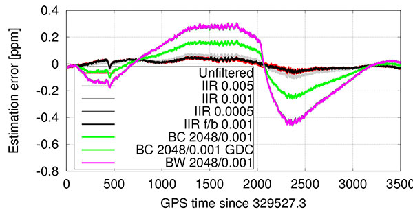
The filters used are summarized in Table 1, where filters #1 and #2 were used in our previous research. In the table, BC denotes a box-car FIR filter implementation, and BW refers to an approximated brick-wall filter (truncated sinc in time domain). Although the order of the filter is higher, all feedback coefficients (an) other than the first a1 are zero for stability reasons. The stated bandwidth is the 3 dB bandwidth of the filter, (fwd/bwd) indicates forward and backward filtering, and GDC indicates group delay compensation.
Table 1. Filter implementations for temperature measurements.
Carrier-phase positioning. It is well known that carrier-phase measurements can deliver much higher accuracy positions than pseudorange measurements. The challenge for MEMS oscillators is to mitigate the phase noise of the resonator, and any noise resulting from temperature compensation, to allow continuous phase tracking. Failure to do this will result in more cycle slips, which in turn will limit the benefits of using carrier-phase measurements (since the navigation filter will have to more frequently re-estimate the carrier-phase ambiguities).
Testing
The static data set collected in our earlier research was reused for this work. The data was collected from a static rooftop antenna, while the TSMO was placed inside a temperature chamber, which was performing a temperature cycle from +85° to –30° C and back up to +60° C. The temperature compensation polynomial (Figure 1) was fit using the clock drift estimate from running the software receiver with the same data set without any temperature compensation. The temperature filters in Table 1 were then applied to the raw temperature measurements, and processed with the same software receiver as in our earlier work, allowing for direct comparison of the results.
Carrier-phase positioning. To mitigate effects from orbit and atmospheric errors, first a zero-baseline test was carried out on a rooftop antenna on the CCIT building at the University of Calgary. Two identical IF sampling front-ends with a sampling rate of 10 MHz were used for each of the tests, one utilizing a built-in TCXO and the other using the external MEMS oscillator clock signal. A commercial GNSS receiver was used as a static base for this setup. The TSMO and TCXO based front-ends were used as a rover, all connected to the same antenna. For all tests, only GPS L1 C/A signals were used by the devices under test.
Second, a short-baseline test utilizing two antennas about 2.5 m apart was carried out, with the same equipment. For reference, surveyed coordinates of the antennas’ base mounts were used. For these two tests, the front-ends and oscillators were at constant temperature (to within variation of room temperature) on a desk.
Third, two road tests in a car driving around Springbank airport close to Calgary were performed. One test involved smooth driving only, and the second test was performed by rough driving over uneven roads so that higher accelerations on the oscillators were provoked. To allow a performance comparison between the TCXO and TSMO based receivers, the two front-ends were used as rover receivers at the same time and were connected to the same geodetic-grade antenna mounted on the vehicle’s roof.
Equipment and processing. All samples from the IF-sampling front-ends were processed with the University of Calgary’s GSNRx software GNSS receiver to obtain code and carrier phase as well as Doppler measurements. These measurements were subsequently processed with the University of Calgary’s PLANSoft GNSS differential real-time kinematic (RTK) software to obtain a carrier-phase navigation solution.
As a reference, a commercial GNSS/INS system using a tactical-grade IMU was used. The dual-frequency, multi-GNSS, carrier-phase post-processing of the reference data provided a reference position of better than 1 cm estimated standard deviation in all three axes, which is in the following referred to as “truth.”
The kinematic tests were carried out with the PLAN group’s test vehicle, a GMC Acadia SUV-style vehicle. A geodetic-grade antenna was mounted in close vicinity to the LCI tactical-grade IMU as shown in Figure 2. The antenna was split to a reference receiver and the two IF-sampling front-ends. The front-ends were rigidly mounted to each other as well as to the TSMO board to ensure similar accelerations on both oscillators. The front-ends were placed in the center of the passenger cabin.
Figure 2. Equipment setup on PLAN group’s test vehicle.
The kinematic tests were performed near the Springbank airport close to Calgary, Alberta. For a base station, a commercial dual-frequency receiver was set up on an Alberta Survey Control Marker with surveyed coordinates. A leveled antenna was used with this receiver, and 20 Hz GPS and GLONASS raw measurements were collected to provide a base for both the reference receiver and the receivers under test.
Results
First, we compared results from improved temperature filtering to results from our earlier work. The performance of temperature measurement filtering is quantified with regard to frequency accuracy (mainly arising from filter group delay) and phase-lock indicator values of the tracked signals, which are mainly deteriorated from noise introduced by temperature compensation.
The best performance with regard to PLI (Figure 3) was achieved using the forward-backward 1-tap IIR filter (#4 in Table 1).
Figure 3. Cumulative histogram of PLI with temperature compensation.
While the estimation error introduced by this low-bandwidth and high group delay filter was significant especially at fast temperature changes before and after the temperature turnaround point at 2067 s into the run (Figures 4 and 5), the forward-backward filtering cancels a major part of that delay. Note that this filter has even lower bandwidth (Table 1) than the same filter used in forward-only filtering, as the resulting magnitude response squares with the forward-backward filtering approach.
Figure 4. Temperature-based estimation of oscillator error.Figure 5. Error in temperature-based estimation of oscillator error (note the larger error due to filter delay).
Only a slight performance decrease can be seen when using a boxcar filter with 2048 taps, but only when compensating for the FIR part’s known group delay of approximately 1 s. It is noted that filters #4 and #6 — which show best performance — are only usable in post-processing or with significant latency.
In contrast to group-delay compensated filters, which might not be applicable in low-latency, real-time applications, the even lower bandwidth 1-tap IIR filter — although introducing a still significant group delay — resulted in best tracking performance amongst the filters, which are not compensated for any group delay. This filter’s performance is surprisingly followed by the low-complexity 1-tap IIR filter (#3) ahead of the filters implementing the boxcar (#5) or brickwall (#7) filter blocks. The reasoning for this lower performance — given the results of the equal coefficients but group delay compensated filter (#6) performance — can be found in the higher delay of the measurements compared to the group delay compensated filter. The difference between boxcar and brickwall filter was found to be negligible with this data set.
In general, the receiver was able to provide very good carrier-phase tracking using all of the proposed filters. The satellite signals were tracked with a PLI of better than 0.86 between 98 to 99.8 percent of the time, depending on the implemented filter; this corresponds to approximately 30 degrees phase error or 2 cm ranging error at the L1 frequency.
Short baseline test. Both receivers correctly fixed the ambiguities within 150 s, kept the ambiguities fixed until the end of the data set, and computed the correct position with an estimated accuracy of better than 1 cm in each axis. The position estimate error is comparable between the two receivers, and slightly higher than in the zero-baseline test because multipath errors are no longer removed. Figure 6 shows the position estimates errors for both receivers. No significant systematic errors are evident in the position errors from these tests. The slowly varying error in height is typical for multipath signals.
Figure 6. Short baseline position estimates error for TSMO (top) and TCXO (bottom) based receivers. The color bar at the bottom denotes the ambiguity status: all fixed ambiguities (green), partially fixed ambiguities (yellow) and float-only ambiguities (red).
The double-differenced phase residuals are slightly higher for both receivers than in the zero-baseline test (not shown), but follow the same trend for both receivers and are therefore accredited to the signals or processing software rather than to the oscillator.
The phase-lock indicator values for all satellites are visualized in a cumulative histogram in Figure 7. Because the TSMO based receiver’s PLI values are on average slightly smaller than for the TCXO based receiver, higher noise is expected in those measurements. Nevertheless, in the processed data sets, this has no significant effect on the estimated position.
Figure 7. Cumulative histogram of PLI values for TSMO and TCXO-based receivers in short baseline test.
Kinematic Tests
The first test was performed on paved rural roads. Any road unevenness was avoided where possible, or driven over fairly slowly where unavoidable. The test started with an approximate 150 s static time to assure initial fixing of the ambiguities, and continued with driving in open-sky and occasional foliage environment.
As visualized in Figure 8, both receivers were able to fix the ambiguities correctly within roughly 30 s. During the test, both receivers fell back to partially fixed or float ambiguities. The TCXO based receiver computes a partially fixed solution between 650 s and 1200 s, as apparent from the position errors in Figure 8. In the same interval, the TSMO based receiver computes a float-only solution.
Figure 8. Smooth driving road test position estimates error for TSMO (top) and TCXO (bottom) based receivers.
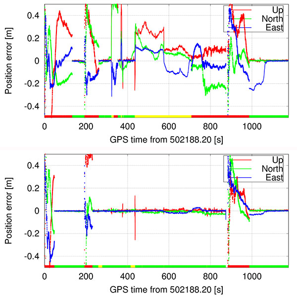
Bumpy Driving. The second test route was chosen to include several locations of road unevenness and a slightly elevated bridge (bump) over a small stream, which was driven over at five different speeds, ranging from approximately 20 to 74 km/h.
Both receivers were able to compute a sub-meter accurate position during the entire test. While the TCXO based receiver was able to compute a fixed ambiguity position with centimeter-level accuracy during the majority of the test, the TSMO based receiver was able to fix the ambiguities at significantly fewer epochs and reverted to a float ambiguity most of the time, decreasing positioning accuracy to the decimeter-level. From Figures 9 and 10 the times of higher acceleration (>5 m/s) when driving over the bridge (between 260 and 490 s into the test) correlate well with the times of reduced number of fixed ambiguities, and therefore times where the navigation engine is reverting to a float ambiguity carrier-phase solution.
Figure 9. Bumpy driving road test position estimates error for TSMO (top) and TCXO (bottom) based receivers.Figure 10. Bumpy driving road test number of total and used satellites, and vehicle excess (>5 m/s) accelerations for TCXO based receiver.
At approximately 562 s into the test, the vehicle hit a larger puddle on the dirt road resulting in high vertical acceleration (> 1g). Despite this high acceleration, the TCXO based receiver stayed in fixed ambiguity resolution mode, and the TSMO based receiver continued in partially fixed ambiguity solution mode.
At 875 s into the test, the car passed underneath two separated two-lane highway bridges, which led to a loss of all signals on all receivers, including the reference receiver. Both receivers reacquired the signals after the underpass and fixed the ambiguities again after approximately 100 s.
Conclusion
Temperature-measurement filter implementations were presented that outperform the previous low-complexity implementations, but at the cost of higher computational requirements, more latency or even real-time capability because of the more complex design or non-causal filtering approach. Using the proposed filtering approach, the eight strongest satellites were tracked in phase-lock tracking state for 98–99.8 percent of the test time, while performing a full hot-cold temperature cycle.
Furthermore, we showed the performance of traditional double-differenced carrier-phase positioning using a receiver with a temperature-sensing MEMS oscillator. Static and kinematic tests were performed, and the operation of an otherwise identical TCXO based receiver at the same time allowed to compare the oscillator’s performance in several environments as well as their sensitivity to accelerations. Carrier-phase positioning with TSMO based GNSS receivers was possible with accuracies better than typically required for automotive applications.
Manufacturers
The temperature-sensing MEMS oscillator was produced by Sand 9, which has been acquired by Analog Devices, Inc. A NovAtel 701GG geodetic-grade antenna was mounted on the test vehicle and a NovAtel SPAN-SE was the reference receiver. A NovAtel ProPak-V3 was the base station, with a Trimble Zephyr antenna.
Bernhard M. Aumayer is a Ph.D. candidate in the Position, Location and Navigation (PLAN) Group in the Department of Geomatics Engineering at the University of Calgary. He worked for several years as a software design engineer in GNSS related R&D at u-blox AG.
Mark Petovello is a professor in the PLAN Group, University of Calgary. His current research focuses on software-based GNSS receiver development and integration of GNSS with a variety of other sensors.
This article is based on a technical paper presented at the 2015 ION-GNSS+ conference in Tampa, Florida.
BRG Sports and 360fly have announced a full line of “smart” helmets, integrated with 360fly’s 360-degree 4K video, at CES 2016.
All four helmets feature an integrated 4K camera, capable of also shooting conventional 16 by 9 pixel video. The video capabilities are driven by 360fly’s mobile app.
Shooting at 2,880 by 2,880 pixels at up to 30 FPS, the integrated camera includes a built-in GPS sensor to tag locations, and a barometer/altimeter and accelerometer powered by the Qualcomm Snapdragon 800 processor.
Selected BRG Sports’ motorcycle, mountain bike and snow helmets will feature the 360-degree 4K video, mobile editing and sharing, and other digital capabilities, including Bell Star with 360fly, Bell Moto 9 Flex with 360fly, Bell Super 2R with 360fly and Giro Edit with 360fly.
“The benefits of integrating digital video and intuitive digital technology into action sports helmets is a ground-breaking advancement for our sports,” said Terry Lee, executive chairman and CEO of BRG Sports. “This ‘smart helmet’ collaboration with 360fly is yet another landmark milestone within our 60-year history of helmet innovation and industry leadership.”
The integrated 360fly camera is detachable, allowing it to be utilized independent of the helmet by the user.
360-Degree video camera
360fly also unveiled the 360fly 4K camera, the next generation of its 360fly camera, on display in Central Hall booth No. 10417 at CES 2016. The 360fly 4K is a water-resistant, single-lens, 360-degree video camera with live streaming capabilities and intuitive filming and editing advancements.
360fly 4K adds a new image sensor that quadruples the resolution of the first generation 360fly camera, producing 360-degree 4K quality. It pairs with its Micro-HDMI accessory base giving it the ability to output a real-time full 360-degree HD video stream.
Like the original 360fly camera, 360fly 4K comes standard with Bluetooth, built-in Wi-Fi and has up two hours of battery life.
The camera also still has the ability to share video content direct from the 360fly iOS and Android mobile app to popular social platforms like Facebook and YouTube.
Harris Corporation has expanded a collaboration with Boundless to further extend its capabilities in open-source geospatial technology. This partnership makes it easier and more cost-effective for customers to access, manage and share the huge amount of location-based data available from devices, sensors and satellites, the companies said.
Most recently, Harris has developed a geospatial data warehouse called One Object One Time (1O1T), which eliminates redundant data and stores the most current representation of geospatial objects such as a lighthouse or communications tower. This capability ensures data currency and significantly reduces the time required for processing and delivering content and products compared with traditional methods.
Harris is using 1O1T to provide content management services and create high-quality data and products for use by a wide variety of government and commercial customers.
Boundless’ OpenGeo Suite is an open-source enterprise geospatial software bundle. It expands Harris’ existing offerings like 1O1T. Boundless experts support and consult around the implementation of OpenGeo Suite components including GeoServer, PostGIS, Open Layers and QGIS.
“We like Boundless’ savvy and nimble approach to providing open-source geospatial software and services,” said Tim Ellis, director of Harris’ IntelliEarth geospatial business. “This is a very productive collaboration for both companies and most important, our customers.”
“Harris provides top-notch, responsive products for some of the most important geospatial initiatives in the world,” said Boundless CEO Andy Dearing. “Together, we are extending the possibilities of the open-source geospatial platform.”
Qualcomm Technologies, Tencent and Zerotech announced and demonstrated at CES 2016 a commercial drone based on the Qualcomm Snapdragon Flight platform. The Consumer Electronics Show is being held this week in Las Vegas.
Tencent, China’s largest Internet service portal, and drone maker Zerotech have co-designed Ying, a small, lightweight drone that can be easily controlled right from a smartphone, leveraging the companies’ advanced software, and the computational power of the Qualcomm Snapdragon 801 processor, making it easy to capture video that can be streamed directly to your friends using QQ and Wexin.
The Ying drone uses the Snapdragon 4K capture to “supersample” the video image, providing a stabilized, corrected video and picture recording at 1080P as well as first person view at 720p that can be directly streamed or uploaded to Tencent’s drone social community platforms Weixin and QQ. Weixin (“we chat”) is a mobile text and voice messaging communication service developed by Tencent in China, first released in January 2011.
“We continue to bring a range of new research and development products to meet the needs and demands of our customers across various industries,” said Jianjun Yang, founder of Zerotech. “We’re excited to work with two companies who are technology leaders in their space — Qualcomm Technologies who has brought their mobile expertise to the consumer drone industry, and Tencent with its popular social networks, to bring a lightweight, highly integrated consumer drone that enables users to share their photos and videos instantly with their friends.”
“The consumer drone market is expected to soar in the next few years, and Ying is a good example that shows how Tencent is working closely with the fast growing drone market by enriching use cases of our core and leading social communication services,” said Roland Cai, vice president, IEG, Tencent. “Zerotech’s expertise in UAV manufacturing and, Qualcomm Technologies’ highly integrated drone development board coupled with our social networking platforms allows us to provide our hundreds of millions of active users with a competitive price on a high quality drone such as Ying that can share their experiences in real time.”
Snapdragon Flight is a highly optimized 58 x 40 millimeter board targeted specifically for consumer drones and robotics applications. Snapdragon Flight is based on the Snapdragon 801 processor, with GPS, 4K video capture and robust connectivity, along with advanced drone software and development tools, bringing cutting-edge mobile technologies to create a new class of consumer drones.
“Consumer drones are becoming the ultimate selfie camera but with advanced capabilities such as 4K capture and high performance computing and connectivity,” said Raj Talluri, senior vice president, Qualcomm Technologies. “We are tapping into our proven mobile technologies for the exciting drone opportunity and teaming up with Zerotech and Tencent enables us to support smaller, smarter drones that deliver real-time content to China’s largest social media network.”
CES attendees can check out the Ying and other drones and robotics at the Qualcomm Technologies Booth #25824 in South Hall. Attendees can also attend the official launch event for the Ying at Zerotech’s Booth #26035 in South Hall on Jan. 7 at 11 a.m. PT.
The Federal Aviation Administration’s (FAA) drone app — B4UFLY — is being released for Apple, following an initial beta testing period. The app can be dowloaded from the Apple store.
The FAA also is releasing a beta version of B4UFLY for Android devices, which can be downloaded from Google.
B4UFLY tells users about current or upcoming requirements and restrictions in areas of the National Airspace System (NAS) where they may want to operate their unmanned aircraft system (UAS).
“We expect B4UFLY will help raise public awareness about what it means to operate unmanned aircraft safely,” FAA Administrator Michael Huerta said at the Consumer Electronics Show in Las Vegas. “It is another important part of our education and awareness efforts to foster a culture of safety and accountability for the UAS community.”
The B4UFLY app includes a number of enhancements the FAA developed as a result of user feedback during the beta testing announced in May 2015. Within two taps, users know if it is safe to fly at their current location. The app provides a status indicator that tells users: “Proceed with Caution,” “Warning – Action Required,” or “Flight Prohibited.”
The app also features a planner mode that allows users to select a different time and location for an upcoming flight and determine if there are any restrictions at that place and time.
By law, hobbyists who want to fly within five miles of an airport must notify the airport operator and the air traffic control facility (if there is one) prior to flying.
For now, B4UFLY will ask users who are supposed to notify the airport before flying for voluntary information about their planned flight. This will not meet the statutory requirement to notify the airport and air traffic control facility, but the data will help the agency make informed policy decisions related to notification. This information will not be publicly available.
You can find more information on our B4UFLY webpage.
The Arctic SDI Pilot is sponsored by the United States Geological Survey (USGS) and Natural Resources Canada. The goal is to demonstrate to Arctic stakeholders the diversity, richness and value of a Spatial Data Infrastructure (SDI) based on web services and standardized exchange formats in helping address critical issues impacting the Arctic.
Stakeholders include national and pan-Arctic science and monitoring organizations and decision makers engaged in Arctic research, social and economic policy, and environmental management. The organizations participating in the ArcticSDI Pilot will document and publicize best practices that can support a rich network of web-accessible data and service resources for the Arctic.
The pilot has two phases.
Phase 1, an OGC Interoperability Program Concept Development study, began in December 2015. In Phase 1, project planners are building an inventory of currently available Arctic geospatial data layers and web services and defining the Arctic SDI architecture. This work will be supported by partners engaged in industry, research, and numerous jurisdictions. A Request for Information will be published in January 2016 to elicit further ideas, experiences, and projects in industry, research institutions and public administration to make maximal use of the ArcticSDI and to develop it further.
The Arctic SDI Pilot Phase 1 will also provide direct input into OGC’s major Testbed 12 Interoperability Program initiative. USGS has indicated that sponsor funding will be made available for Testbed 12 to test and further develop components identified in the Arctic SDI pilot. Through this collaboration, arctic stakeholders and the Arctic SDI will leverage and benefit from the leading-edge interoperability research, development and outreach that is ongoing in the OGC’s series of major testbeds.
All findings from Phase 1 will serve as input for Phase 2, which will be an OGC Interoperability Program Pilot Project. OGC pilot projects apply and test OGC Standards in operational applications using Standards Based Commercial Off-the-Shelf (SCOTS) products that implement OGC Standards. Pilot projects provide an operational implementation so that users and technology developers can collaborate and learn how to better address their requirements using standards-based architectures.
To articulate the value of interoperability via standards, technology provider participants will implement the recommended Arctic SDI architecture in support of Arctic policy scenarios. A video will be produced to engage policymakers on the benefits of integrating diverse data utilizing Arctic SDI standards and information management best practices.
The OGC is an international consortium of more than 515 companies, government agencies, research organizations, and universities participating in a consensus process to develop publicly available geospatial standards. OGC Standards support interoperable solutions that “geo-enable” the web, wireless and location-based services, and mainstream IT. OGC Standards empower technology developers to make geospatial information and services accessible and useful with any application that needs to be geospatially enabled.
Drone maker DJI is introducing enhancements to its Phantom 3 and Inspire 1 quadcopters at CES 2016, a consumer electronics and technology trade show held Jan. 6–9 in Las Vegas.
\The Phantom 3 4K’s introduction is the result of strong consumer demand for top resolution cameras and ultrasonic sensors, the company said, which enable flight indoors and in areas with a weak GPS signal. The Phantom 3 4K comes with an integrated, gimbal-stabilized 4K camera and has remote-control buttons for playback, video recording and camera shutter.
Instead of DJI’s Lightbridge video-transmission system, the Phantom 3 4K uses built-in WiFi to transmit the video downlink and on-screen data. The drone’s WiFi video downlink is effective up to a distance of 1.2 kilometers.
“The Phantom 3 4K fills an important gap in our Phantom portfolio. It offers a high-quality camera and smart navigation system for a lower price than our professional models. This is possible, as we have replaced the DJI Lightbridge system with a built-in WiFi link,” said Paul Pan, DJI’s senior product manager.
The Phantom 3 4K will stay aloft for 25 minutes on a full battery charge. DJI also has made stylistic change to its Inspire 1 Pro. The Inspire 1 Pro Black Edition comes with a black controller, battery and a shell with a matte finish. It comes equipped with DJI’s best-in-class Micro Four Thirds camera, the Zenmuse X5.
In celebration of DJI’s 10th anniversary, the promotional price of the DJI Phantom 3 4K edition is $799, starting Jan. 6. This promotion also extends to the Phantom 3 Advanced model, now priced at $799, and the Phantom 3 Standard, at $499. DJI says the price may be subject to change.
The original Inspire 1 Pro, with a white shell, battery case and controller, will continue to be sold alongside the new model.
“One of the most-frequent questions we get from professional drone operators is ‘when will DJI come out with a black Inspire?’ The answer is now,’” said Ferdinand Wolf, manager of DJI Studios Europe.
DJI’s main booth at CES 2016 will be in South Hall 2, No. 25602, and Central Hall, No. 9845. The exhibits will feature a flying cage for attendees to attempt flying a drone with First Person View, an Osmo Zone for testing the filmmaking tool, a showcase of solutions created with the DJI SDK and a display of work created by the SkyPixel community.
Drone-maker DJI has launched a public beta version of its new geofencing system in North America and Europe.
Geospatial Environment Online (GEO) will provide drone users with up-to-date guidance on locations where flight may be restricted by regulation or raise safety or security concerns. With this major upgrade to DJI’s existing geofencing system, users will have access to live information about areas temporarily restricted from flight due to forest fires, major stadium events, VIP travel and other changing circumstances.
The GEO system will also show restricted areas around locations like prisons, power plants and other sensitive areas where drone flight would raise non-aviation security concerns.
To accommodate the large variety of authorized applications, GEO will allow drone operators with verified DJI accounts to self-authorize and temporarily unlock flight in some locations. Certain areas where drone flight is not allowed, such as Washington D.C., will remain as unlockable no-fly zones. Unlocking requires a DJI account verified with a credit card, debit card or mobile phone number. DJI will neither collect nor store the information, and the service is free.
The verified account is required only if a user chooses to fly in a location that might raise aviation safety or security concerns.
Use of GEO requires a drone firmware update and installation of a beta version of the DJI Go app.