A team from the National Oceanic and Atmospheric Administration (NOAA) and Raytheon has successfully demonstrated advancements of the Coyote Unmanned Aircraft System (UAS), verifying new technology that improves Coyote’s ability to collect vital weather data on hurricanes.
Coyote drops out of a P-3 weather surveillance plane, spreads its wings and flies straight at a hurricane, braving violent winds and punishing rain to gather weather data and beam it back to meteorologists.
Drew Osbrink and Eric Redweik of Sensintel and NOAA hurricane researcher Joe Cione monitor data from the Coyote as it flies into Hurricane Edouard in 2014. (Photo: NOAA)
Coyote solves a problem that has limited forecasters’ ability to tell how hard a hurricane will hit. The secret behind the storm’s punch lies in what is known as the “boundary layer” — a low-altitude area that includes the surface of the ocean. Because hurricanes are fueled by warm ocean water, information collected at the interface of atmosphere and ocean is vital to the understanding and prediction of a storm’s strength.
“That’s where the energy is extracted from the ocean to the atmosphere,” said Joe Cione, a NOAA hurricane researcher. “Unfortunately, it is too difficult for us to go with manned aircraft to fly down there.”
The Coyote can maneuver in the most violent regions of a hurricane.Traditional weather instruments parachute from a plane and grab only a snapshot of humidity, wind speed and other factors, but Coyote’s winged design enables it to linger and return to certain areas for more measurements.
“Coyote will gather data specifically in the eye wall where it can provide information for forecasters to predict intensity from a safe distance,” said John Hobday, Raytheon. “This is a significant difference for researchers: instead of providing a snapshot of data, it’s a full-length movie.”
The Coyote after a successful flight on Jan. 7. (Photo: NOAA)
Operational Upgrades
In a Jan. 7 test, the Coyote was released from NOAA’s Hurricane Hunter P-3 aircraft and flew over the Avon Park Air Force Range in Florida, to measure the transmission range of upgraded technologies. It set a new distance record for flight control and data transmission to the P-3, and provided hurricane forecasters with real-time data on atmospheric air pressure, temperature, moisture, wind speed and direction as well as surface temperature.
Data collected will help improve the accuracy of forecasts. “Here at the National Hurricane Center (NHC), we are keenly interested in obtaining measurements from the Coyote of the strongest winds near the center of the storm,” said Chris Landsea, science operations officer at NHC. “Coyote could help us paint a better picture of current storm intensity for our storm updates.”
In 2014, NOAA deployed four of the Coyote planes into Hurricane Edouard, a Category 3 storm, at controlled altitudes as low as 400 feet. Scientists on board the P-3 received meteorological data in both the eye of the storm and the eye wall.
However, the P-3 had to fly 5 to 7 miles from the Coyote to pick up its signal. So engineers at Raytheon and the NOAA Aircraft Operations Center upgraded Coyote’s sensor systems and improved its communications package to allow it to talk to the plane over longer distances. Now, Coyote can fly for 50 miles away from the launch aircraft, which will be free to continue its own mission.
Coyote also was outfitted with an upgraded instrument package that includes an infrared sensor to measure sea surface temperature, which will help scientists understand how a hurricane extracts energy from the ocean — and how it might intensify or change. The team also is working toward optimizing battery life.
The test flight verified the Coyote’s ability to transmit the data collected from its instrument package to operators aboard the P-3 as well as at the NHC, where personnel monitor storms and develop forecasts.
NOAA scientist Paul Reasor demonstrates the Coyote. (Photo: NOAA)
u-blox has launched a receiver module that brings real-time kinematic accuracy to the mass market. The NEO-M8P GNSS receiver module delivers high performance down to centimeter-level accuracy.
RTK technologies have been used for some time in low-volume niche markets, such as surveying and construction. Because of high costs and complexity, this enhanced positioning technology has been inaccessible for most other uses.
Emerging high volume markets, such as unmanned vehicles, require high-precision performance that is low cost and energy efficient. Other application areas include agriculture and robotic guidance systems, such as tractors or robotic lawnmowers. The u-blox NEO-M8P answers these demands for a small-sized, highly cost-effective, and very precise RTK-based module solution.
The RTK algorithms are pre-integrated into the module. As a result, the size and weight are significantly reduced, and power consumption is five times lower than existing solutions, cutting costs and improving usability dramatically, u-blox said.
Measuring 12.2 x 16 x 2.4 millimeters, NEO-M8P is a small, high-precision GNSS RTK module based on GPS and GLONASS satellite-based navigation systems.
The module is available in two variants. The NEO-M8P-0 has rover functionality, and the NEO-M8P-2 has rover and base-station functionality. The rover with the u-blox NEO-M8P-0 receives corrections from the u-blox base receiver NEO-M8P-2 via a communication link that uses the RTCM (Radio Technical Commission for Maritime Services) protocol, enabling centimeter-level positioning accuracy.
By using the NEO-M8P module, customers can reduce their research and development efforts, because they do not have to spend significant resources and time to develop an in-house RTK solution on a separate microprocessor system.
“NEO-M8P lowers the barriers for innovative companies looking to develop equipment that needs centimeter-level accuracy in many markets and applications, such as UAVs,” said Daniel Ammann, Executive Director Positioning and Co-Founder of u-blox. “Today, most solutions are based on board-level receiver products. NEO-M8P delivers performance that is simply a level above competitive offerings in terms of size and low-power consumption, thereby providing easy integration into customers’ existing product platforms, as well as a significant saving in their cost of goods.”
u-blox NEO-M8P is available for sampling now and will be shipping in volumes in the third quarter of 2016.
A jammer-hunting UAV employs a radio frequency (RF) detection system and a navigation control scheme. The RF detection component uses a directional antenna and the unmanned aerial vehicle’s (UAV’s) ability to rotate to determine a bearing to the jammer. The navigation control scheme selects a trajectory for making bearing measurements that enable rapid jammer localization, based on three bearing calculation methods: max, cross-correlation, and a modification of max leveraging the shape of the antenna’s main lobe, known as max3.
By Adrien Perkins, Louis Dressel, Sherman Lo and Per Enge
Whether malicious or unintentional, GPS jamming events have already proven to disrupt airports and pose an increased risk to commercial aviation in the future. An important mitigation for this risk is the ability to rapidly locate and interdict the GPS jamming device.
Directional antenna mounted on underside of UAV.
The system must be capable of reliably determining jamming direction and quickly localizing the source in the semi-urban environments typically found in and around airports. This article examines both aspects.
In developing a localization algorithm, the measurements being made by the system can greatly impact performance. Using a directional antenna as the primary sensor, our multirotor platform Jammer Acquisition with GPS Exploration & Reconnaissance (JAGER) can measure the bearing to the jammer, which is the main input into the localization algorithm. Here we examine three different bearing calculation techniques from a gain pattern: max, cross-correlation and max3.
The closed-loop navigation controller uses the gathered information to determine where to go next to most quickly localize the jammer. In this article, the localization objective is modeled as a partially observable Markov decision process (POMDP) to determine the optimal route. The viability of this technique for locating the jammer source is demonstrated through flight testing in a simulated environment.
PROBLEM OVERVIEW
Because our vehicle is an agile, multirotor UAV, it can translate, climb, rotate and make received signal strength indicator (RSSI) measurements at the same time. It is computationally difficult to reason over such a large input space. Therefore, to simplify the problem, we constrain the vehicle to a constant altitude and assume a single, stationary jammer. We also decouple the problem into two actions: rotating — to measure bearing, and moving — to another measurement location.
This article focuses on the first action: How accurately can bearing be estimated if the vehicle samples RSSI values while rotating in place, and how can those measurements affect the decisions of where to rotate next?
POMDP Formulation. The problem of choosing successive rotation locations has been formulated as a POMDP. POMDPs are a principled approach to decision making and closed-loop control in stochastic domains.
At each time step, the problem can be described by a state s ϵ S, where S is the state space, or set of all possible states. To limit the size of the state space, the search area is split into a grid. A state consists of four state variables: the vehicle x-index xv, the vehicle y-index yv , the jammer’s x-index xj , and the jammer’s y-index yj. At each time step, the state is only partially observable — the jammer’s position is unknown.
At each time step, the vehicle can take some action a ϵ A, the set of available actions. In our formulation, the vehicle can travel to any of the neighboring grid cells, rotate in place to make a bearing measurement, or simply hover, resulting in 10 possible actions. After taking action a from state s, the problem will transition to some state s’.
At any time step, the state is unknown to the vehicle. Instead, it makes an observation o ϵ O, where O is the set of all possible observations. In our problem, these observations are the bearing measurements made when the vehicle rotates. To reduce the number of possible observations and computational complexity, the bearing measurements are discretized and include a “null” observation when the vehicle cannot determine a bearing.
The POMDP formulation includes an observation model Z(a, s’, o) = P(o | a, s’) describing the probability of making observation o after taking action a and transitioning to state s’. This probability is a function of the bearing measurement quality. Prior to the work presented here, it was assumed bearing measurements had zero-mean Gaussian noise with a 10-degree standard deviation. It was also assumed that if the vehicle rotated in the same grid cell as the jammer, it would receive the null measurement, because the space directly under the vehicle is outside the main lobe of its directional antenna. An updated observation model, using the characterization performed in this work, can be found in the section entitled “Effect on Algorithm.”
Although the vehicle is unaware of the true state, it maintains a probability distribution over the state space, called a belief, denoted b. After taking an action and making a new observation, Bayes’ law is used to update the belief. This updated belief is used in conjunction with policy π to determine the next action to take. A policy π(b) maps beliefs to actions.
Due to the large belief space, this research uses SARSOP, which allows a policy to be computed offline and uploaded to the vehicle before a mission. The vehicle then relies on this policy to make decisions while in flight.
Generating a policy requires a reward model that encourages the vehicle to perform certain actions. In our formulation, we reward the vehicle when it stops in the grid cell containing the jammer. This encourages the vehicle to first find the jammer, which is our goal. We give penalties for movement and rotations to reflect the time taken to perform them.
EXPERIMENTAL SETUP
Our jammer-hunting UAV, JAGER, is a commercially available DJI S1000. The S1000 is made to carry film-grade cameras, but we’ve modified it to carry our experimental payload. For control and navigation, the vehicle is equipped with a Pixhawk autopilot system running a custom version of the PX4 firmware. The Pixhawk has sensors to determine the vehicle’s attitude, altitude, and position. The localization decisions are made on the flight computer, which is an Odroid-U3 ARM-based computer that communicates with the autopilot throughout the flight. All signal strength measurements are made with a directional yagi antenna connected to the RN-XV WiFly module. A schematic of this configuration and the flow of information can be seen in Figure 1.
Figure 1. Schematic of components on UAV.
Given the small size of this payload, the flight time achieved during testing was 20 minutes on 4 pounds of batteries (two 6-cell 8000-mAh batteries).
Signal Source. Due to restrictions on active interference with GPS signals, a 2.4-GHz Wi-Fi router was used as a proxy jammer for all our flight testing. The Wi-Fi router was placed on the ground at a surveyed location. In these tests, GPS was used for navigation as we are still developing alternate and GPS jamming resistant navigation.
Antenna. A single the L-com HG2409Y yagi antenna was used for this experiment. This 2.4-GHz Wi-Fi antenna has a 60-degree beam width both horizontally and directionally as shown in Figure 2. As depicted in the opening graphic, the antenna was mounted below the vehicle in order to have the clearest view to a ground based signal. Furthermore, the antenna is placed angled down at 30 degrees in order to have the main lobe of the antenna extend out to the horizon. This also leaves a cone underneath the vehicle with a weak signal that was aimed to be leveraged as a null measurement when over the jammer.
Figure 2. Directional antenna gain pattern from datasheet: vertical, left; horizontal, right.
While we are currently using a Wi-Fi-based system to stand in for GPS, we eventually plan to test this system on a true GPS jammer. Despite the different frequencies, the same methodology and approach will be able to be used when localizing a GPS jammer. The biggest change the system will require is the antenna required to make bearing measurements. For Wi-Fi, we have been able to successfully use an off-the-shelf directional antenna, but for GPS either a custom directional antenna or a dual-antenna solution will be needed.
Measurements. Throughout the UAV’s flight, the directional antenna makes RSSI measurements at 2 Hz. To calculate bearing from a given location, the vehicle simply rotates at a rate of 15 degrees/second at that position and combines all of the RSSI measurements using magnetometer data to form the antenna’s gain pattern. This gain pattern can then be used to estimate the bearing of the signal source from that given position. In this paper that bearing calculation is done with three different methods: max, cross-correlation and max3.
The max method simply finds the maximum RSSI value in the measured pattern and uses that heading as the bearing to the jammer.
The cross-correlation method normalizes the measured pattern and compares it with the known truth pattern for the antenna. The truth pattern is shifted by some angle γ. The cross-correlation is computed for every possible shift γ. The shift yielding the highest cross-correlation coefficient is taken to be the bearing to the jammer.
To get our truth pattern, we sampled RSSI every 10 degrees at distances ranging from 10 to 40 meters, normalized the resulting patterns, and took the mean of these normalized patterns.
The max3 method is an improvement on the max method where the bearing is the mean of the bearing of the two crossings of 3 dB below the maximum RSSI value for the pattern, as depicted in Figure 3.
Figure 3. Depiction of Max3 method.
Flight Area. Test flights were performed at the Joint Interagency Field Experimentation (JIFX) event hosted by the Naval Postgraduate School. Most measurement were taken at an altitude of 100 feet AGL with a handful of measurements made near the signal source at an altitude of 50 feet AGL. When the localization algorithm was tested, a 9 by 9 grid (each cell 11 meters on a side) was used as the world, with the signal source located in the top right cell and the vehicle starting in the center cell, 62 meters from the signal source.
RESULTS
During flight tests with the JAGER vehicle, 88 different experimental gain patterns were created, and bearing calculations were made with each of the three previously described methods.
The POMDP-based localization algorithm was successfully executed to locate the signal source. Leveraging the performance results of the cross-correlation and max3 methods, the model for the POMDP was updated and produced a significantly different flight profile. In addition to the POMDP-based localization algorithm, a baseline algorithm was also used to demonstrate the advantages of the POMDP-based algorithm.
Effects of Distance. Throughout the experiment, measurements were made at distances from the signal source ranging from directly overhead to almost 350 meters away. Figure 4 shows all the locations in which measurements were taken during flight tests, with the signal source in the center of the main grouping. Each marker represents one measurement, and its color represents roughly the maximum RSSI value measured at each location. As expected, as the vehicle traveled further from the signal source, the maximum RSSI value measured dropped. Near the signal source, the signal is no longer captured by the main lobe, which result in poor measurements, as can be seen by the grouping of orange and red markers near the source.
Figure 4. Location of all experimental gain pattern measurements colored by signal strength (from -65dBm, green, to -80dBm, red).
MEASUREMENT CLASSIFICATION
Because of effects of distance on the measurements and the configuration of the antenna on the vehicle, all measurements were split into three classifications: near, ideal and far.
Near. Near measurements are measurements made where the signal source is within the cone underneath the vehicle, where the main lobe of the antenna no longer reaches. When the signal source was near the vehicle, we did not obtain null measurements, but rather obtained gain patterns such as the one shown in Figure 5. These gain patterns do not resemble the ideal gain pattern of the antenna due to the noise in the measurements from the signal source not being picked up by the main lobe, making it challenging for any of the bearing calculation methods to successfully determine the bearing.
Figure 5. Gain pattern at 7 meters from signal source (Near).
Far. Far measurements are any measurement further than 200 meters from the signal source. At these distances, the RSSI measurements were at or below the receiver sensitivity. At these distances, the resulting gain patterns no longer had enough measurements to clearly resemble the ideal gain pattern of the antenna. Figure 6 shows a gain pattern from 250 meters away with a true bearing of 267 degrees and demonstrates the partial pattern that is measured. The cross-correlation estimate of 182 degrees suffers from the inability to match the partial pattern with the required truth pattern. On the other hand, the simplicity of the max and max3 methods result in more accurate estimates of 271 and 285 degrees, respectively.
Figure 6. Gain pattern at 250 meters from signal source (Far).
Ideal. This leaves the ideal category, which is any measurement made between near and far. At this distance, the signal source was able to both be within the main lobe of the antenna and within reasonable rage of the WiFly’s sensitivity. In the ideal range, the gain patterns produced resemble the true pattern of the antenna, as shown in Figure 7.
Figure 7. Gain pattern at 26.6 meters from signal source (Ideal).
In the flight tests, the majority of the measurements taken were in the ideal range. Only a few measurements were made in the far range so no detailed analysis is presented for measurements in the far range.
BEARING METHODS PERFORMANCE
An overview of the standard deviation of all the results can be seen in TABLE 1.
Table 1. Standard deviation [deg] of calculated bearing for each method.As expected, each of the methods had approximate zero mean Gaussian error distributions for the overall and ideal cases as depicted in Figure 10 for cross-correlation. Overall, Max3 outperformed the other two methods. The noise in the measurements near the signal source made each of these methods unreliable, with all three having very high standard deviations as shown. At ideal distances, max3 and cross-correlation performs similarly while max is a little worse.
Figure 10. Distribution of errors for cross-correlation technique for different distance classifications.
The proper characterization of the antenna is vital to the performance of the POMDP localization algorithm. Using the results presented with the max3 and cross-correlation methods, the POMDP model can be updated to better reflect the measurements in order to improve the flight profile for localization.
Max. The max method is the simplest method used to calculate the bearing to the signal from a given set of measurements. This method is also the reason for the poor performance in calculating the bearing. This method can too easily pick a wrong estimate if there is a spike in what should be a smooth main lobe as depicted in Figure 11. These spikes cause a large spread in the errors in calculating bearing seen in Figure 8.
Figure 8. Bearing error as a function of distance for max technique.
Cross-Correlation. Cross-correlation is the most complex of the methods used and in the ideal range is one of the best performing methods (on par with the max3 method).
The overall performance of the cross-correlation suffered from the poor performance near and far from the router. Since this method requires a known truth pattern, when the experimental measurements don’t yield enough results to create a full pattern, the cross-correlation can mistakenly identify the partial pattern for a side lobe instead of a main lobe as was seen in Figure 6.
In the ideal range, it greatly outperforms the max method as expected. When looking at the bearing error shown in Figure 9, it can be seen that the errors are much more tightly grouped near zero than those seen in Figure 8 for the max method. The outliers for the far measurement caused by a failure to match the partial patterns to the truth can also be clearly seen in this figure.
Figure 9. Bearing error as a function of distance for cross-correlation technique.
The increase in performance from near to ideal can clearly be seen in Table 1, where the standard deviation of the error is significantly smaller for the ideal case.
Max3. Max3 is the strongest of the three bearing calculation methods tested; overall, it performed the best and max3 has the advantage of simplicity over cross-correlation. It can perform on par with cross-correlation in the ideal range as can be seen by the similarly close error groupings in Figures 12 (max3) and 9 (cross-correlation) and by the similar standard deviations seen in Table 1.
Figure 12. Bearing error as a function of distance for max3 technique.
The benefit over the cross-correlation method of not requiring a known truth pattern allows max3 to perform well when the number of measurements is very small and the gain pattern is mostly incomplete. However, max3 has difficulty making accurate bearing calculations when close to the router, though not as badly as the other two methods.
The advantage max3 has over the simple max is well illustrated in Figure 11. While the gain pattern looks very promising, there is a spike along the otherwise mostly smooth main lobe at 116 degrees. This spike is off from the true 92-degree bearing which results in the max method estimating an incorrect bearing. By taking the mean of the bearing of the two crossing points 3 dB below the max (marked in blue x’s), effects from spikes like the ones depicted are reduced allowing for a much better estimate of 93 degrees.
Figure 11. Gain pattern explaining benefits of Max3 method over max.
Through this characterization, the performance seen from max3 can be used to update the POMDP model to improve the localization algorithm, as described in section “Effect on Algorithm.”
ALGORITHM PERFORMANCE
One of the goals of our flight tests was to determine the feasibility of the POMDP approach and begin to understand the performance of the POMDP method. A simple baseline method was used for comparison. The baseline method used in this test was a variable step greedy algorithm that moved in the direction of the calculated bearing (using the max method) with a variable step size. The step size was based on the similarity between measurements, resulting in an increased step size when moving in the same direction toward the signal source.
Using this baseline method, JAGER was able to move toward the location of the signal source, and with the assistance of a user monitoring the behavior, was able to locate the signal source. The flight path of the vehicle for this test can be seen in Figure 13.
With a user in the loop with this baseline method, a good estimate of the location can be determined by watching the behavior of the vehicle. Looking at Figure 13, it can be seen that the vehicle kept crossing its path near one location, which can be determined to be an estimate of the location of the signal source. It is worth noting that the baseline method does take four steps to get in the region of the signal source, and then another four or five steps for the user to be confident that the vehicle is in the vicinity of the signal source.
Figure 13. Flight path of the variable step size, greedy localization algorithm. White lines are true bearing from measurement locations, red lines are cross-correlation bearings and black lines are max bearings.
POMDP Localization. With a baseline determined, the POMDP approach was executed from the same starting location and used the simple max bearing method for determining bearing from each location. This localization took a mere two steps and three measurements to be able to locate the signal source. Figure 14 shows the state updates as the vehicle made subsequent measurements. After the first measurement is made at the starting location, the vehicle is able to immediately narrow down the location of the signal source to a small region within the grid.
Figure 14. POMDP signal source belief state at each step. Darker the red in the cell, the more likely the signal source is in that location.
Unlike the simple method of moving slowly in the direction of the max bearing, the POMDP method can make large changes in order to get to the next best location to make a measurement.
When running this algorithm, we had an assumption that when the vehicle is in the same cell as the signal source, a null measurement would be made. Unfortunately, near and over the signal source resulted in noisy measurements, and that noise resulted in location of the signal source being off by one cell.
Effect on Algorithm. The experiments in this paper were performed to obtain a better observation model for the localization algorithm. Previously, the model assumed 10-degree noise except when the vehicle was in the same cell as the jammer; there the modeled assumed a null measurement would be obtained. These assumptions were used in the experimental trajectory shown in Figure 15 and affected the selected trajectory. The vehicle always moved toward regions with high probability of containing the jammer (the dark red cells). Because we assumed that rotation would only yield a null measurement when over the jammer, receiving a null observation after rotating would convince the vehicle that the jammer was in its current cell. For this reason, the vehicle moves to regions with high probability of containing the jammer; it hoped to receive this high-information measurement and solve the problem with a single rotation.
Figure 15. Flight path of the POMDP localization flight with an overlay of the final grid state.
Experimental results have shown that measurement noise increases greatly close to the jammer. Our new model assumes 40-degree noise if the jammer is in any of the adjacent grid cells when the vehicle rotates, and 13-degree noise if the jammer is farther away. If the vehicle rotates in the same cell containing the jammer, it no longer receives a null measurement. Instead, it can receive any measurement with uniform probability.
Generating a policy with this new model leads to different trajectories. A simulated rerun of the experimental trajectory from Figure 15 is shown in Figure 16. The vehicle avoids the darker cells, which indicate higher probability of containing the jammer. Instead the vehicle chooses to rotate in cells it believes are farther away from the jammer to avoid possible measurement noise.
Figure 16. Simulation steps of POMDP with updated model.
CONCLUSION
This article presents the development of the localization component of a UAV to locate the source of a GPS jamming signal. For the scenarios tested, modeling the localization as a POMDP is a viable solution that can locate a static signal source in very few steps. It is faster and has greater confidence than a simple, greedy search baseline solution.
Through extensive test flights using a single directional antenna and rotation-based measurements, three different bearing methods have been analyzed. All three methods suffered when near the signal source due to the antenna reception pattern, which resulted in very noisy measurements. Of the three, max3 and cross-correlation fared the best in the ideal distance from the signal source. Max3 was able to outperform cross-correlation when the UAV was far from the signal source due to the limitations of cross-correlation requiring a truth pattern for correlation. However, cross-correlation can also provide a useful correlation coefficient that can be used in the future to merge several bearing calculation methods.
The characterization of antenna bearing performance is a vital component to the localization process. The characterization affects the optimal behavior determined by POMDP. When we changed our initial assumptions about measurement performance near the jammer to one better informed by our tests, the actions determined POMDP resulted in a significantly different profile.
ACKNOWLEDGMENTS
The authors gratefully acknowledge the Naval Postgraduate School for providing an unmatched space to be able to perform test flights of the JAGER system at the Joint Interagency Field Experimentation events. The authors would also like to thank the Stanford Center for Position Navigation and Time (SCPNT) and its members for supporting this work.
MANUFACTURERS
The JAGER UAV airframe is a S1000 octocopter by DJI Innovations; the flight batteries are a 8000 mAh model by Hextronik; the autopilot hardware and GPS antenna is a Pixhawk by 3D Robotics, Inc.; the autopilot software is based on PX4 by Pixhawk.org. The tracking hardware comprises a 2.4 GHz Yagi antenna from L-com; an RN-XV Wi-Fi module by Roving Networks; and an Odroid-U3 computer by Hardkernel Co.
Adrien Perkins is a Ph.D. candidate in the GPS Research Laboratory at Stanford University, where he received his MSc. in aeronautics and astronautics.
Louis Dressel is a Ph.D. candidate in the Aeronautics and Astronautics Department at Stanford, where he works on a joint project with the Stanford Intelligent Systems Lab and the GPS Research Laboratory.
Sherman Lo is a senior research engineer at the Stanford University GPS Laboratory.
Per Enge is a professor of aeronautics and astronautics at Stanford, where he directs the GPS Research Laboratory.
This article is based on a technical paper presented at the 2015 ION-GNSS+ conference in Tampa, Florida.
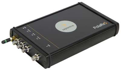
Next generation for precise scientific and geodetic applications
The PolaRx5 offers 544 hardware channels for robust and high-quality GNSS tracking. The receiver supports all major satellite signals including GPS, GLONASS, Galileo and BeiDou, as well as regional satellite systems including QZSS and IRSS. Septentrio’s Advanced Interference Mitigation (AIM+) technology enables it to filter out both intentional and unintentional sources of radio interference, from narrowband signals over high-powered pulsed signals to chirp jammers and Iridium interferers. Septentrio’s APME+ multipath mitigation technology eliminates short delay multipath without introduction of bias and guarantees superior measurement quality. The user can deactivate APME+ to obtain unmodified measurements.
Bentoni is a positioning antenna for all of the global public satellite constellations: GPS, GLONASS, BeiDou and Galileo. It is designed to be used in trackers, portable devices, network components, drones and wearable electronics. It offers high performance and maintains good isolation in situ within a device. Bentoni is a flexible FPC antenna in Antenova’s flexiiANT product range. They are supplied with an I-PEX MHF connector and a 1.13 mm RF cable in a choice of three lengths. They can be folded to save space in operation within a device, with the aim being plug-and-play simplicity. The antennas are self-adhesive mounted so that they can easily be fixed inside an electronic device.
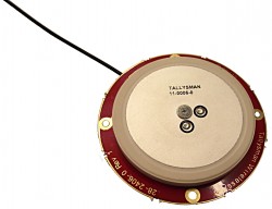
The Tallysman TW2926 antenna is an unhoused OEM version of the TW2920, designed for simultaneous reception of L-band correction signals and all of the upper band GNSS signals, including GPS L1, GLONASS G1, Galileo E1 and BeiDou B1. The TW2926 is 56 millimeters in diameter and has four drilled plated holes for secure mounting within customers’ products. It can be custom tuned to ensure optimal performance within an enclosure. The 1-dB bandwidth of both the TW2920 and TW2926 covers 1525–1559 MHz for the L-band downlink and 1559–1610 MHz for the upper-band GNSS. The LNA provides 28-dB of gain. The antennas employ Tallysman’s Accutenna technology, which provides strong cross-polarization rejection for greatly improved multipath rejection, low axial ratio and tight phase center variation.
The Near Field Communication (NFC) 88NF100 controller with active load modulation (ALM) is desgined to support the smallest antenna sizes critical to mobile, the Internet of Things (IoT), wearable and automotive applications. Adhering to NFC Controller Interface (NCI) Technical Specification version 1.1, the 88NF100 provides an extended operating range and is extremely energy efficient to enable extended battery life for power-critical applications. ALM technology supports the smallest antenna sizes to enable OEMs to implement NFC capabilities into small form-factor designs. The controller has extremely low power operation in polling mode to provide increased battery life for power critical applications and three single-wire protocol (SWP) interfaces to secure element (eSE) devices for secure payments. The two-pin antenna interface supports a maximum distance of two meters between the chip and antenna.
Designing Better Maps: A Guide for GIS Users, second edition, is an updated and comprehensive guide to creating maps that communicate effectively. Cartographer Cynthia A. Brewer covers the basics of good cartography, including layout design, scales, projections, color selection, font choices and symbol placement; she also describes her ColorBrewer application, an online color selection tool. The second edition includes a new chapter on map publishing. One reviewer wrote, “It is also worth a look by experienced cartographers who seek a refresher and a few new tips.” Brewer is a professor and chair of the Department of Geography at Pennsylvania State University and map and atlas design consultant.
Eos Pro Tools is tightly integrated with google map
Eos Pro Tools is a comprehensive RTK NTRIP app for Android that works with its Arrow line of RTK GNSS receivers. An Arrow GNSS receiver combined with the NTRIP app turns an Android smartphone or tablet into a powerful data collector capable of recording 1-centimeter accurate GIS data in real-time. The app, named Eos Tools Pro, has user-configurable audible and visual alarms to alert the user of high PDOP, lost RTK correction, unacceptable correction age and several other important metrics. It supports all current and future constellations (GPS, GLONASS, Galileo and Beidou). Detailed satellite information such as a skyplot that plots each visible satellite, whether it’s being used or not, and signal strength bar graphs from each constellation are also displayed. Finally, a terminal screen displays the NMEA data flowing and allows the user to send commands to the receiver.
Lightweight, ergonomic design for the mobile workforce
The 7-inch Algiz RT7 Android tablet is fully rugged, meeting stringent MIL-STD-810G U.S. military standards for protection against drops, vibrations and extreme temperatures. Its IP65 rating means that it’s waterproof as well as fully sealed against sand and dust. The tablet comes with a built-in accelerometer, gyroscope and e-compass as well as a stand-alone u-blox EA-7M GPS receiver for navigation, along with built-in Qualcomm IZat location services.
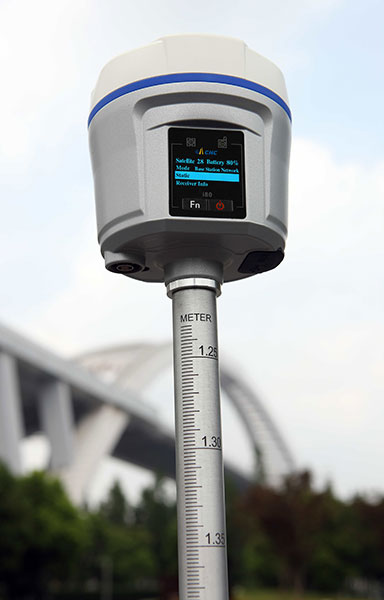
The i80 GNSS receiver computes a true triple-frequency real-time kinematic (RTK) tilted pole solution using all four worldwide and multiple regional constellations, providing a future-proof sub-centimeter RTK solution to surveyors and contractors. Without the need of a data collector or computer, the i80’s LCD graphic user interface allows for common workflow operations, such as static logging, autobase, autorover and UHF channel selection, to be easily performed. The CHC i80 incorporates dual hot-swappable batteries, allowing for days of uninterrupted work. While small and lightweight, it is packed with a full array of sensors and modules: multiple micro-electrical-mechanical (MEMS), internal Tx/Rx UHF, multiband cellular modem, Wi-Fi, Bluetooth, serial and USB.
All-in-one GPS, GNSS and RTK Data Collector Series
The SXPro series is built for mobile survey and GIS users for applications such as water, electric and gas utilities; transportation; mining; agriculture; and forestry. The professional-grade rugged handheld receivers include a battery life of more than 10 hours on a charge as well as a large outdoor-viewable touchscreen. The handhelds are rated IP65 for protection against water and dust, and equipped with a 5-megapixel autofocus camera and Microsoft utilities. The SXPro RTK (real-time kinematic) model offers 220 multi-constellation channels for centimeter accuracy with RTK networks. The SXPro GNSS offers 372 multi-constellation channels for sub-meter accuracy with SBAS corrections.
New point cloud analysis and visualization capabilities
The latest release of ENVI software adds lidar point cloud analysis and visualization capabilities that previously were only available in the ENVI lidar software package. ENVI 5.3 offers users a single software interface to work with hyper-spectral, multi-spectral, panchromatic and lidar data. The out-of-the-box functionality includes 3D point-cloud visualization, derived terrain product generation (such as digital elevation models) and lidar analytics such as viewshed line-of-sight calculation. For users who need point-cloud or terrain products in an area where collecting lidar is not feasible or is too expensive, the ENVI Photogrammetry Module is able to generate synthetic 3D point clouds from stereo optical imagery to take advantage of existing imagery archives. The dimension of time can be critical for a thorough geospatial analysis of an area, and the new ENVI release has added enhancements to the Spatio-Temporal analysis toolset. Spatio-Temporal analysis visualizes change and derives statistics from data over time, enabling users to observe past events to better predict upcoming activities.
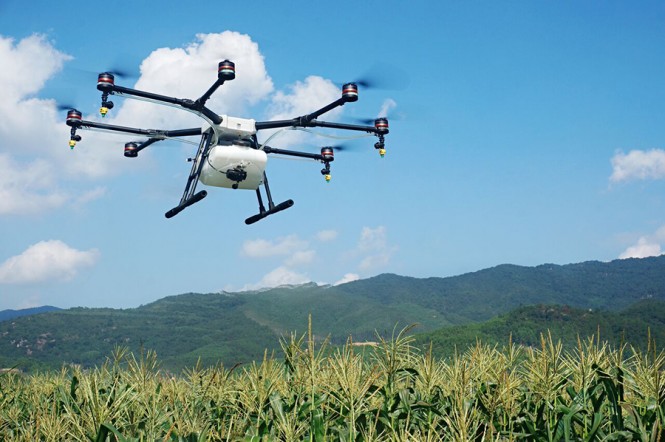
The eight-rotor DJI Agras MG-1 UAV can load more than 10 kilograms of liquid for crop-spraying and can cover between seven and 10 acres per hour — more than 40 times more efficient than manual spraying. It can fly up to eight meters per second and adjusts spraying intensity to flying speed to ensure even coverage. It is dustproof, water-resistant and made of anti-corrosive materials. It features DJI’s flight-control system and microwave radar to ensure centimeter-level accuracy. During flight, the drone scans the terrain below in real time, automatically maintaining its height and distance from plants to ensure application of an optimal amount of liquid. The drone’s intelligent-memory function means after the Agras MG-1 is brought back to base for refill or recharge, it will return to its last memory point to pick up spraying where it left off.
The EXCIPIO is an anti-drone system that uses a drone to shoot out a net to capture another drone.The EXCIPIO Aerial Netting System is comprised of a UAS equipped with a first-person view camera and a net-firing gun. When the EXCIPIO has reached the threat target, it fires a net, then can either release the net with the target ensnared or keep the net tethered. Though the initial system concept was focused on intercepting and neutralizing an airborne UAV, the conceptual applications have expanded to include manned aircraft, ground vehicles, people and animals (whether airborne or on the ground).
UAV company DJI is offering its first tuned propulsion system designed for all-weather use in industrial applications and filmmaking.
The E2000 propulsion system has the power to handle add-ons such as computing devices and advanced imaging equipment. It uses a combination of 6010 motors, 1240S/X field-oriented control (FOC) electronic speed control (ESCs), and 2170 propellers to carry payloads of 1800–2500 grams (g) per axis, with a maximum thrust of up to 5100 g/rotor (50V, sea level).
The 6010 motor’s bearings are fully sealed to prevent flu
ids such as salt water from causing corrosion. A special surface coating applied to the stator also greatly improves its ability to withstand rusting.
To more effectively dissipate heat generated under intensive industrial use, the 6010 motor features an integrated centrifugal cooling system that effectively cools the motor while keeping dust and micro particles out. The 1240S FOC ESC is equipped with a silica thermal pad and heat sink for maximum heat transfer and dissipation.
The E2000 is available in Standard and Pro versions to meet the demands of professional and industry users. Both the 6010 Standard and Pro motor bearings are fully sealed to prevent fluids like rain, pesticide, and salt spray from entering and causing corrosion. A special surface coating applied to the stator also greatly improves its ability to withstand rusting.
The same effective weather sealing has also been applied to the external 1240S ESC found with the E2000 Standard. The E2000 Standard has an IP56 rating.
Carnegie Mellon University and Sikorsky Aircraft researchers have used an autonomous helicopter and an autonomous ground vehicle to demonstrate for the U.S. Army that ground and air robots can perform complex, cooperative missions, the university announced Jan. 20.
During the Oct. 27 demonstration, an unmanned Black Hawk helicopter picked up an unmanned ground vehicle (UGV), flew a 12-mile route, delivered the UGV to a ground location and released it. The drop-zone collaboration promises to keep warfighters out of harm’s way, enabling them to perform missions more effectively.
An unmanned Black Hawk delivers an autonomous ground vehicle to a remote site in a demonstration for the U.S. Army of a joint robotic air-ground mission. (Photo: CMU)
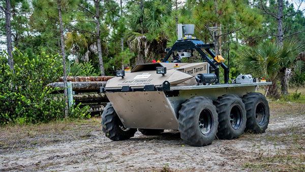
The Black Hawk was equipped for autonomous operation by Sikorsky, a Lockheed Martin Co. It delivered a Land Tamer autonomous unmanned ground vehicle from Carnegie Mellon’s National Robotics Engineering Center (NREC) to a remote site, where the vehicle performed environmental monitoring for potential contamination, the type of robotic mission that could prevent warfighters’ exposure to hazardous conditions, such as chemically or radiologically contaminated areas.
“We were able to demonstrate a new technological capability that combines the strengths of air and ground vehicles,” said Jeremy Searock, NREC technical project manager. “The helicopter provides long-range capability and access to remote areas, while the ground vehicle has long endurance and high-precision sensing.”
The demonstration took place at Sikorsky’s Development Flight Center in West Palm Beach, Florida, for the Army’s Tank Automotive Research, Development and Engineering Center (TARDEC).
Once the helicopter lowered the vehicle to the ground, the Land Tamer drove itself off its transport platform to commence its leg of the mission. The vehicle, equipped with sensors for detecting chemical, biological, radiological or nuclear contamination, then found and surveyed several potentially contaminated sites, autonomously traversing six miles in the process.
When the vehicle sensors detected potential contamination, operators were able to switch the vehicle from autonomous operation into a tele-operated mode for a more detailed exploration of the site.
The helicopter delivered the Land Tamer, Carnegie Mellon’s unmanned ground vehicle. (Photo: CMU)
“The teaming of unmanned aerial vehicles and unmanned ground vehicles, as demonstrated here, has enormous potential to bring the future ground commander an adaptable, modular, responsive and smart capability that can evolve as quickly as needed to meet a constantly changing threat,” said Paul Rogers, TARDEC director.
NREC has developed the unmanned Crusher off-road vehicle for the Defense Advanced Research Projects Agency (DARPA), the Advanced Platform Demonstrator for TARDEC and a tactical unmanned ground vehicle, called Gladiator, for the U.S. Marines, as well as advanced off-road autonomous driving technology. NREC was also part of CMU’s Tartan Racing Team that won the $2 million 2007 DARPA Urban Challenge robot race with its autonomous SUV called Boss.
The Black Hawk helicopter used in the demonstration was a UH-60MU model, equipped for “fly-by-wire” operation. Sikorsky installed its Matrix technology, which it has been developing since 2013.
In the demonstration, a Black Hawk helicopter equipped with Sikorsky’s Matrix autonomy kit flew NREC’s Land Tamer all-terrain vehicle, slung beneath the aircraft in a specially designed cage, to a remote area.
The Navy and Marine Corps’ RQ-21A Blackjack unmanned aircraft system (UAS) received the official green light for operation Jan. 13, marking a major milestone for the program.
The program has achieved Initial Operational Capability (IOC), announced Marine Corps Deputy Commandant for Aviation Lt. Gen. Jon Davis. IOC confirms that the first Marine Unmanned Aerial Vehicle Squadron (VMU) squadron is sufficiently manned, trained and ready to deploy with the RQ-21A system.
“We are ‘go for launch’,” said Col. Eldon Metzger, program manager for the Navy and Marine Corps Small Tactical Unmanned Aircraft Systems Program Office (PMA-263), whose team oversees the Blackjack program. “Achieving IOC designation means the fleet can now deploy using this critical piece of intelligence, surveillance, and reconnaissance architecture to enhance mission success.”
An RQ-21A Blackjack in flight during testing aboard USS Mesa Verde (LPD-19) in 2015. The Marines will deploy for the first time with the unmanned air system this summer. (U.S. Navy photo)
In December 2015, builder Insitu delivered the first system from low-rate initial production (LRIP) lot 3 to VMU-2. The Blackjack system will support of the 22nd Marine Expeditionary Unit (MEU), based in Camp Legeune, North Carolina. The Marines will make their first shipboard deployment with the system this summer.
“The Blackjack team has endured many long hours seeing this program to fruition and I am very proud to lead such a dedicated team of professionals,” Metzger said.
A Blackjack system is comprised of five air vehicles, two ground control systems, and launch and recovery support equipment. At eight feet long and with a wingspan of 16 feet, the air vehicle’s open-architecture configuration is designed to seamlessly integrate sensor payloads, with an endurance of 10-12 hours.
The expeditionary nature of the Blackjack, which does not require a runway for launch and recovery, makes it possible to deploy a multi-intelligence-capable UAS with minimal footprint from ships.
As the 2016 legislative session kicked off this month, the Association for Unmanned Vehicles Systems International (AUVSI) has been tracking all active legislation pertaining to unmanned systems. This year, to provide the best information to its members, legislators, regulators and the media, AUVSI has organized data on all unmanned systems-related state legislation into a sortable, interactive map with details that include a summary of each bill.
Included are bills that place restrictions on police, recreational or commercial unmanned aircraft systems; legislation that forms unmanned systems or autonomous vehicle commissions and task forces; bills that try to treat unmanned technology differently than other information-gathering devices; and bills that place operating limitations on unmanned aerial systems (UAS) in specific scenarios such as preventing all UAS from flying over prisons or from interfering with hunting and fishing.
To date, more than 150 active bills in more than 30 states have either carried over from 2015 or been introduced this year.
Piksi is a low-cost, high-performance GPS receiver with real-time kinematic (RTK) functionality for centimeter-level relative positioning accuracy.
Its small form factor, fast position-solution update rate, and low-power consumption make Piksi ideal for integration into autonomous vehicles and portable surveying equipment. An open-source architecture with a high-performance DSP on-board and our flexible correlation accelerator make it the perfect platform for GNSS research.
Piksi is designed for autonomous vehicle guidance, such as formation flight and autonomous landing; GPS/GNSS research; and surveying systems.
Swift Navigation is a San Francisco-based startup building centimeter-accurate GPS technology for automotive, surveying, robotics, agriculture and drones.
The company says its products are 100 times more accurate than the GPS in a cell phone, at a tenth of the price of the competition.
In November, the company raised $11 million in a series-A investment round led by Pierre Lamond and Lior Susan at Eclipse Ventures. Swift Navigation plans to use the funds for taking current customers to scale and growing their team, with a focus on core engineering. Another focus continues to be research and development, with a second new product due out this year.
Insurance companies in the U.S. and Canada have jumped on the UAV bandwagon, with many now offering coverage for commercial drone users. The insurance usually covers liability for any damage caused by the drone, with comprehensive options covering damage to the drone itself.
Unmanned Risk Management, which also insures helicopters and other aircraft, has insured drones in all 50 U.S. states and in other countries, and has insured the seven film operators that received Section 333 exemptions.
ProSight Specialty Insurance, which operates in the U.S. and UK, was given a Best in Biz Award partly for creating insurance for drone operators. ”It’s so prescient and forward-thinking given the burgeoning use of drones in today’s business world,” said a Best in Biz judge.
AIG has developed commercial UAV coverage designed for the exposure faced by remotely piloted, semi-autonomous and fully autonomous aircraft.
In Canada, Intact Insurance’s UAV coverage caters to small and medium-sized businesses that use or plan to use drones in their business operations.
Meanwhile, a Chicago law firm is now specializing in federal commercial drone law. Antonelli Law became the first law firm in the U.S. to be invited by drone maker DJI to participate in the company’s referral program for commercial drone users to help them receive Section 333 exemptions from the Federal Aviation Administration (FAA). In 2015, Antonelli Law filed more than 50 petitions with the FAA.
The firm also launched a specialized drone law service for police and fire departments, community colleges, universities and municipalities obtain FAA exemptions.
The Federal Aviation Administration (FAA) has awarded more than 3,000 Section 333 Exemption Grants to allow individuals, businesses, non-profits and governmental agencies to fly drones.
FAA Section 333 exemption grants allow unmanned aerial vehicle (UAV) operators to fly commercially and provide professional services. Companies use UAVs for bridge inspections, roof inspections, movie and television filming, aerial photography, pipeline inspections, engineering, precision agriculture, mapping and surveying, wedding photography, real estate photography and videography, public event recording, security and surveillance, live video feeds, training, education, and disaster and catastrophe events.
First responders such a police, fire and other governmental agencies use UAVs f0r search-and-rescue operations, aerial surveillance, security and arson and fire investigations.
Registration for Hobbyists
Nearly 300,000 owners have registered their small unmanned aircraft in the first 30 days after the FAA’s online registration system went live. Owners who registered in the first month received a refund for the $5 application fee.
“I am pleased the public responded to our call to register,” said U.S. Transportation Secretary Anthony Foxx. “The National Airspace System is a great resource and all users of it, including UAS users, are responsible for keeping it safe.”
The agency continues to see a steady stream of daily registrations. While the refund period expired today, the fee will still cover all the small unmanned aircraft that owners intend to use exclusively for recreational or hobby purposes.
“The registration numbers we’re seeing so far are very encouraging,” said FAA Administrator Michael Huerta. “We’re working hard to build on this early momentum and ensure everyone understands the registration requirement.”
The FAA’s registration rule, which took effect on Dec. 21, 2015, applies to small unmanned aircraft that weigh between 0.55 lbs. and 55 pounds. Owners of these aircraft must register before they fly outdoors. People who operated their small unmanned aircraft before December 21 must register by Feb. 19, 2016. The current online system is only available for owners who intend to use their small unmanned aircraft exclusively for recreational or hobby purposes. The FAA is working to make the online registration system available for non-model aircraft users — such as commercial operators — by March 21.
Registration is simple and is done online. Once the owner enters the required information — complete name, mailing address, physical address and email address — they receive a registration number and certificate that they can print out. The certificate includes the registration number that must be marked on all aircraft that meet the registration requirement. Registration is valid for three years.
In addition to being an education opportunity, registration helps new flyers become part of the safety culture that has been deeply embedded in traditional aviation for more than a century, while still allowing for the recreation and innovation that are staples of American aviation.
A new study from U.K.-based Juniper Research has found that annual revenues from commercial drones sales are expected to reach $481 million this year, up 84 percent from last year’s figure of $261 million.
The new research — “Drones: Consumer & Commercial Applications, Regulations & Opportunities 2015-2020” — found that a low price point had significantly reduced the barrier to entry in many sectors, with high-performance models now available for less than $3,000. It claimed that the reduction in drone price points had in turn resulted in their commercial application within an array of new fields including mapping, inspection and monitoring.
Agriculture to Lead Growth. The research argued that strongest growth would occur within the agricultural sector, which Juniper expects to account for 48 percent of all commercial drone sales this year. Here, UAVs (unmanned aerial vehicles) help save time and costs over other methods, such as walking fields on foot and using planes for fly-over filming. Furthermore, the ease of use of a UAV created for the sector allows for more regular crop surveying.
Film and Television. The research also found that demand for UAVs in the film and television sectors is soaring. Drones provide a much cheaper and more flexible alternative to the use of helicopters and other methods to capture footage for the film and TV industry, particularly for action sequences.
Delivery Drone Concerns. The research cautioned that a raft of privacy, safety and security concerns mean that the usage of drones for delivery purposes is likely to be severely constrained or even prohibited within built-up areas.
According to research co-author Windsor Holden, regulators would be extremely wary of allowing planned services such as Amazon Prime Air and Google’s Project Wing to be offered, except as a means of delivering to isolated rural communities.
“Regulators are understandably concerned that the deployment of delivery drones in inner cities would significantly increase the risk of potentially fatal collisions with cars or even pedestrians,” Holden warned.
Terrorist Concerns. The research also claimed that there was a danger that delivery drones could be hacked by terrorists, conceivably delivering an explosives payload into areas where they would be capable of causing high levels of civilian casualties.
According to Juniper Research, the report:
details and segments the various UAVs available in the market.
assesses how drone development will proceed in light of stringent safety and privacy concerns and regulatory hurdles.
analyses key market drivers, technological trends and challenges that currently influence market potential.
determines scenarios that will impact future demand.
provides in-depth forecasts across a range of key metrics.
Also, a new white paper, “Game of Drones,” is available to download from the Juniper website together with further details of the full research and the attendant Interactive Forecast Excel (IFxl).