The U.S. Air Force has awarded Lockheed Martin a $45.5 million contract to provide military code (M-code) early use (MCEU) capability to the Global Positioning System (GPS).
Part of the Air Force’s overall modernization plan for the GPS, M-code is an advanced, new signal designed to improve anti-jamming and protection from spoofing — as well as increased secure access — to military GPS signals for U.S. and allied armed forces.
MCEU will provide command and control of M-code capability to eight GPS IIR-M and 12 GPS IIF satellites on orbit, as well as future GPS III satellites, which the Air Force expects will begin launching in 2018.
MCEU is envisioned as a way to accelerate M-code’s deployment to support testing and fielding of modernized user equipment in support of the warfighter.
The Military Code (M-Code) Early Use (MCEU) contract will accelerate deployment of command and control of M-code capability to GPS IIR-M and GPS IIF satellites currently on orbit, as well as future GPS III satellites (like GPS III SV02 above). (Photo: Lockheed Martin)
The U.S. Air Force’s MCEU contract directs Lockheed Martin to upgrade the existing Architecture Evolution Plan (AEP) Operational Control System (OCS), allowing it to task, upload and monitor M-code within the GPS constellation. The contract includes new software and hardware development that will be deployed in 2019 to worldwide ground facilities that support the Air Force’s GPS.
“When people think of GPS, they often think of the satellites that provide the signals, but do not remember the important ground system behind it,” said Mark Stewart, Lockheed Martin’s vice president for Navigation Systems. “We recognize the ‘ground’ is critical for any major space mission constellation and we are proud that we can help the Air Force with this part of their GPS modernization plan.”
The AEP OCS — maintained by Lockheed Martin under the GPS Control Segment (GCS) Sustainment Contract — controls the 12 GPS IIR, 8 IIR-M and 12 IIF satellites in orbit today. The company has successfully implemented several recent projects to modernize and sustain the system for the Air Force.
In June, Lockheed Martin deployed the first of its state-of-the-art GPS Monitor Station Technology Improvement Capability (MSTIC) receivers at Cape Canaveral Air Force Station. The software-defined MSTIC system replaces 30-year-old hardware, positioning the Air Force to take advantage of commercial off-the-shelf technology enhancements in processing power, reliability and cybersecurity in the future. Six Air Force AEP OCS monitoring stations around the world will receive the MSTIC upgrade by the end of 2017.
In February 2016, the Air Force awarded Lockheed Martin the GPS III Contingency Operations (COps) contract to upgrade the AEP OCS with new capabilities so it could support the more powerful, next-generation GPS Block III satellites. The COps program passed a successful Critical Design Review milestone with the Air Force in December 2016.
Also in 2016, under the GCS contract, Lockheed Martin completed the commercial off-the-shelf upgrade No. 2 (CUP2) project — part of a multi-year plan to modernize the AEP OCS’ technology and enhance the system’s ability to protect data and infrastructure from internal and external cyber threats, as well as improve its overall sustainability and operability. CUP2 is now fully operational and managing the current GPS constellation.
Boundless has partnered with the Global SOF Foundation, a 501(c)(3) non-profit organization that aims to build and grow an international Special Operations Forces (SOF) network of military, government, commercial and educational stakeholders.
The foundation fosters SOF objectives and partnerships to confront both global and networked threats.
“We’re honored to partner with an organization that supports national and international Armed Forces in such an important way,” said Andy Dearing, CEO of Boundless. “The work conducted by Global SOF plays an integral part in safeguarding national security and supporting critical decision-making; two initiatives that we’re proud to stand behind.”
The Global SOF Foundation aids the support and growth of the international SOF network. Besides working with its partners to promote SOF capabilities, it contributes to the unification of the SOF community through a variety of annual convening forums.
The foundation also informs national security policy to ensure the proper development, sustainment and resourcing of SOF.
“We are thrilled to have Boundless on board,” said Stu Bradin, president and CEO of the Global SOF Foundation and U.S. Army Special Forces colonel (ret.). “They were recommended to us by one of our long-term partners, so we know they are the real deal. We are excited to see what they can bring to the international SOF community.”
Boundless offers a complete open GIS solution through a unique combination of technology, products and experts, to give enterprises deeper intelligence and insights into their location-based data. The Boundless platform is built upon open source technology and open APIs that generate actionable location intelligence across third-party apps, content services and plugins for enterprise applications.
In the battle for reliable positioning and timing, the U.S. Army is engaged in a multitude of activities, including mounted and dismounted A-PNT (assured position, navigation and timing) systems, anti-jam technology and pseudolites.
The idea is simple: Take some GPS satellites, and put them on or near the ground. Now you have a navigation system where you have full control over the locations and power of the transmissions. You can ensure that the transmissions reach places that GPS normally struggles with, such as deep urban canyons, forests and valleys.
You can turn up the transmit power, so they are much harder to jam than spaceborne GPS signals. These pseudo-satellites, commonly referred to as pseudolites, have seen steady interest over the years for a variety of applications.
Now the U.S. Army is pursuing the use of pseudolites as part of its initiative to maintain operation in GPS-denied environments.
Pseudolite Basics
There are various types, and use-cases, of pseudolites. In this column we’ll consider the direct-ranging pseudolite, which can be simply considered as a ground-based GPS satellite. If we deploy several pseudolites on the ground, we can imagine that a normal GPS receiver would be able to receive the GPS-standard transmissions and derive a position, just as we would from the space-based satellite transmissions.
The fact that the pseudolites are ground-based introduces us to the first consideration: The locations of the transmitters are no longer described by orbital parameters. Instead of calculating the position of satellites, we need to describe the location of the pseudolites in geographical terms, perhaps with a fixed position described in Earth-centered, Earth-fixed (ECEF) coordinates.
The transmitted navigation data message, which would normally contain almanac and ephemeris information, may now need to contain the geographical position of the pseudolite. Not a problem, but our GPS receivers will need a software upgrade to be able to handle this situation.
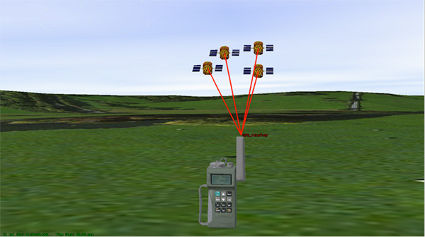
The deployment of the pseudolites themselves poses an interesting problem. Imagine a military scenario, where the army is deployed to a region of interest. Navigation warfare is taking place, and GPS is frequently jammed in the region.
High-power pseudolites are deployed to allow the army to navigate despite the jamming, using the same standard-issue GPS receivers that soldiers are familiar with.
The first problem is, having placed your pseudolites in position, how do you know where they are?
You might choose to place your pseudolites at locations that have previously been surveyed, so you know where they are in advance. But this isn’t likely, particularly if you’ve just moved your troops into an unfamiliar area. You might also want to move the pseudolites regularly, as the army moves to new ground. So the pseudolites need to determine their own position, and the easiest way for at pseudolite to determine its own position is with GPS, of course.
Isn’t this a bit incestuous? If we’re using pseudolites because GPS is jammed, how does the pseudolite get its position? This is why military pseudolites will typically be fitted with some form of anti-jam technology, such as a controlled radiation pattern antenna. This allows the pseudolite to receive GPS satellite signals in the presence of jamming, determine its own position, and transmit that as part of its own navigation message.
So, now that we can get pseudolite locations, the next consideration is: Where should pseudolites be placed?
A-DOP-ting a Good Layout
If you know about GNSS, you’ll be familiar with the concept of dilution of precision (DOP). This is essentially a measure of how accurate your position estimate is likely to be, due to the geometry of the satellites: a good wide spread of satellite positions gives us better accuracy.
Figure 1. Poor satellite geometry, resulting in high DOP. (Image: Michael Jones)Figure 2. Good satellite geometry, resulting in low DOP. (Image: Michael Jones)
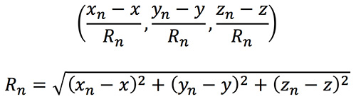
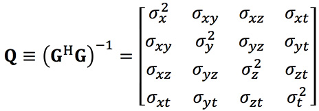
The DOP can be easily calculated by forming a covariance matrix of the geometry, expressed in an appropriate coordinate frame. If (xn, yn, zn) denotes the position of the nth pseudolite, and (x, y, z) the position of the receiver, we can express the unit vectors from the receiver location to the pseudolite location:
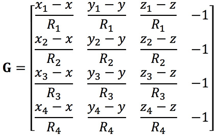
We then form a matrix of these unit vectors:
Finally, we form the covariance matrix from which we can extract the DOP values:
From the elements of this matrix we can determine the various DOP metrics. Let’s concentrate on horizontal DOP (HDOP), given by:
When positioning using GPS satellites, we are blessed with a Walker constellation that generally gives us a nice spread of satellite locations (unless we’re in an urban canyon). On the battlefield, using pseudolites, we do not have the same luxury.
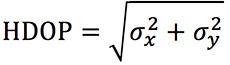
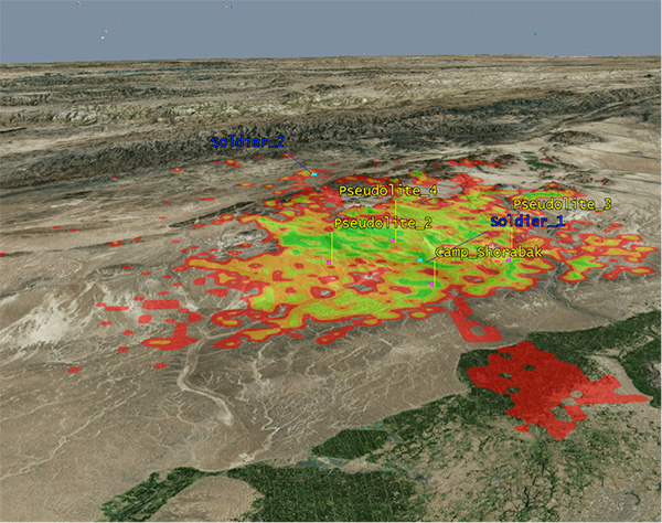
Let’s consider a scenario: a conflict in Helmand province, Afghanistan. An operating base is established at Camp Shorabak, where a pseudolite is operating, and three further pseudolites are deployed in the field. This is shown in figure Figure 3.
Figure 3. Scenario with four pseudolites. (Image: Michael Jones)
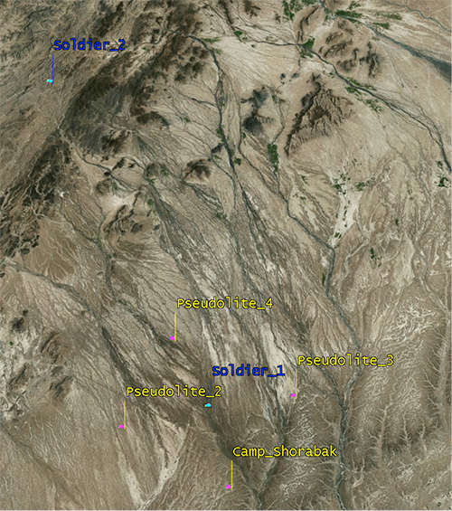
Taking a look at Figure 4, we can see what this means for HDOP. The regions shaded green represent locations where our HDOP is less than 2.5, and the red areas represent an HDOP greater than 50.
Soldier #1 is surrounded by the four pseudolites, which is a pretty nice arrangement: We get an HDOP of around 2.4. But if we now consider soldier #2, located a bit further out, we get a very different picture.
Here we have an HDOP of 64, which is fairly terrible. It’s not really that surprising looking at the geometry — to soldier #2 the pseudolites all appear in a similar direction. Soldier #2 cannot expect to achieve good positional accuracy in this arrangement.
Figure 4. HDOP for the Afghanistan scenario. (Image: Michael Jones)
So getting a good geometric spread of ground-based pseudolite locations could be a bit of a challenge, especially if the operating area is constantly moving and changing. The next thing to think about is getting enough height.
Getting the Height Right
When we perform positioning using GPS, we typically track several satellites, which have a range of elevations. Many GPS receivers will choose to ignore the satellites at low elevations, such as those within 5 degrees of horizontal, because those satellites are generally the least reliable. They may be partially obscured, and subject to more noise and fading.
Ground-based pseudolites all have very low elevations by definition. Unless the terrain is perfectly flat and smooth, pseudolites quickly become obscured. Even with flat ground, pseudolite signals will disappear behind the horizon after a few kilometers.
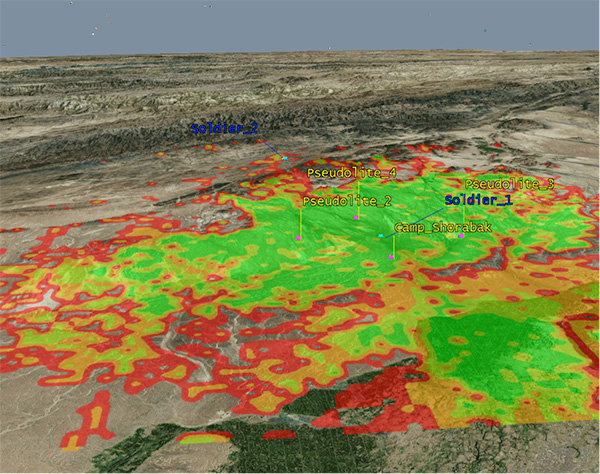
Let’s go back to our Afghanistan scenario again. This time, instead of looking at DOP, let’s look at the geographical coverage of our four pseudolites. Here we’ll assume that our user, the soldier, is 2 meters (m) high, and the pseudolite antennas are mounted at a height of 20m above the ground. That’s pretty high — the army will need to erect some masts.
Figure 5 shows what we get. The green areas are locations where our soldier can see all four pseudolites; yellow three, orange two, and red one. At all other locations, no pseudolite signals can be seen at all. You can quickly see that the range isn’t great — terrain, even small undulations in the ground, is a line-of-sight killer. Add some buildings and trees and the situation gets worse. Reduce the height of our pseudolites below 20m, and the situation gets worse. Soldier #1 can receive three pseudolite signals, but soldier #2 has no hope in this case.
Figure 5. Pseudolite visibility at 20m antenna height. (Image: Michael Jones)
Let’s raise the height of the antennas to a fairly crazy 100m above ground (Figure 6). As expected, we get much better coverage, but soldier #2 still has a problem. To get good signal coverage over any sizable area, you really do need to get those antennas as high as possible.
Figure 6. Pseudolite visibility at 100-m antenna height. (Image: Michael Jones)
Augmenting GPS
Often, we don’t want to rely on pseudolite signals alone. If GPS is available, we clearly want to make use of it, and so we want to use a mixture of both GPS satellites and pseudolites. Consider working in a region of sporadic GPS reception, such as an urban environment or forest. We can usually receive a couple of good GPS satellites, but we also need a couple of pseudolites to help us get a complete navigation solution.
Coming back to one of our original objectives, which is to avoid redesigning the GPS receiver hardware, we need to make sure that our receivers can receive and process both GPS satellite signals and pseudolite signals simultaneously. To achieve this, we can decide to make our pseudolites transmit GPS-standard signals, and make use of unassigned spreading codes to essentially create new satellites in the constellation.
But we quickly run into a problem. GPS satellites are always a distance of around 20,000 kilometers away, and the received signal strength is also fairly constant: around –158.5 dBW. This is a very small signal, as we all know, sitting well below the noise floor. When we suddenly bring high-power pseudolites into the mix, we have quite a nasty problem to deal with.
Near, Far, Wherever You Are
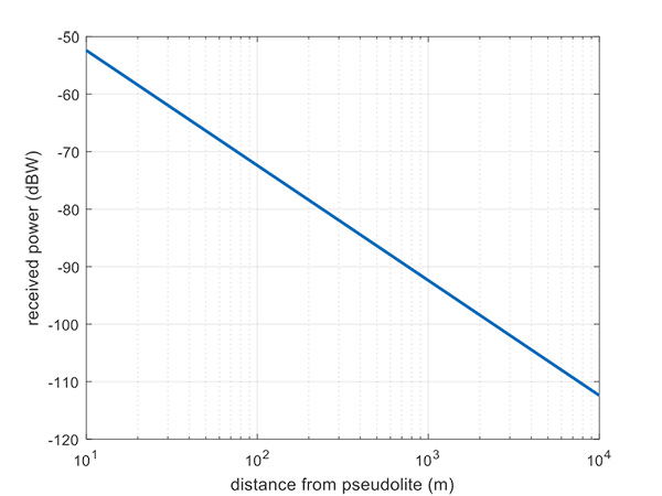
Let’s say, for argument’s sake, we have a pseudolite transmitting with a power of 1 watt. Conducting a basic link budget analysis gives us the plot below and suggests that, at a distance of 10 km from the pseudolite, we can expect to receive the signal at around –112 dBW. This is way above our GPS satellite signal level, but might be manageable by a receiver. Now consider a receiver at a distance of 100 m from the transmitter: we receive a power of –72 dBW, which is huge.
In our quest to augment GPS and make it more robust, we have in fact created a GPS jammer, and achieved exactly the opposite. As with any radio communications link, the received power is extremely sensitive to the distance (varying with the square of distance). In pseudolite terminology, this is known as the near/far problem.
Figure 7. Theoretical received power for a 1-W pseudolite, under ideal conditions. (Figure: Michael Jones)
The near/far problem has given engineers headaches for quite some time. Essentially, the problem comes down to: How can our GPS receivers handle such a massive dynamic range of expected signals? Especially if our objective is to avoid modifying the GPS receiver hardware, if at all possible.
How can a receiver handle the high power of a close-up pseudolite, which is to all intents a jammer, whilst simultaneously receiving the tiny GPS satellite signals from space? Various solutions have been proposed over the years, but one of the current favorite techniques involves pulsing the pseudolite signal.
The idea, then, is to only turn on the pseudolite periodically, essentially applying a duty cycle to the transmission. If a pseudolite isn’t transmitting, it can’t interfere with the normal GPS signals. There are a couple of things to take into consideration here:
What should the pulse duty cycle be, to enable both satellites and pseudolites to be tracked?
How does the GPS receiver behave when presented with alternating large and small signals?
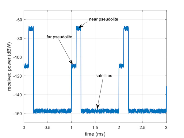
A mathematical analysis of duty cycle effects is beyond the scope of this column, but consider Figure 8 for a qualitative view. Here we have two pseudolites operating alongside GPS satellites. The duty cycle chosen here is for the pseudolite to be operational for 10% of a 1 millisecond integration period. This gives enough time, when the pseudolite is not transmitting, for the low-level GPS satellites to be tracked.
The second pseudolite, which is closer and therefore higher power, transmits for a further 10% slot after the first pseudolite. You can see that each additional pseudolite eats into the time available for tracking GPS satellites, and degrades the signal-to-noise ratio. There are some tricks you can play, such as transmitting multiple pseudolites at the same time if you know they will be similar power levels, but it can get complicated.
Figure 8. Received power versus time, for a pulsed pseudolite scenario. (Figure: Michael Jones)
The Importance of Gain Control
How the receiver copes with the large differences in received power level depends largely on the design of the RF front-end in the receiver. Most GPS receivers will have a certain amount of automatic gain control (AGC), which is a feedback loop designed to keep power levels constant. Many GPS receivers, though, simply aren’t designed with enough AGC to handle pseudolite-level signals (think GPS jammers again).
Military receivers, though, tend to have greater RF handling capabilities, and more bits in the ADC, so are better-suited to the situation. It is then a question of making sure the AGC loop responds in an appropriate time, compared to the duty cycle of pulses.
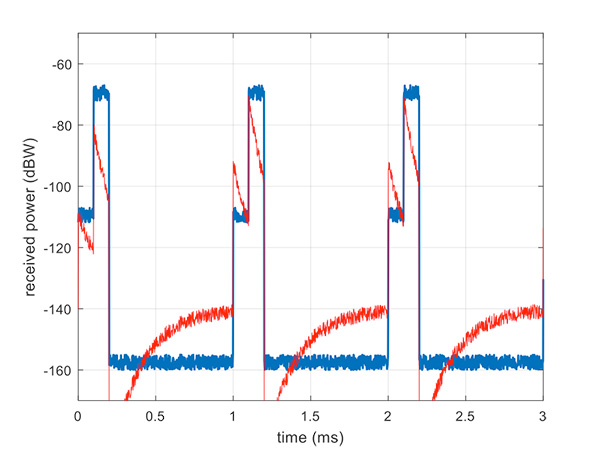
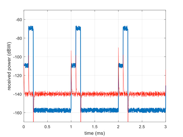
Figure 9 illustrates a slow AGC response, which is not particularly suitable. Compare this with Figure 10, where we have a fast AGC response, quickly adapting to the switches in power level. A receiver with this characteristic will be better able to track both pseudolite and satellite signals.
Figure 9. Pulsed pseudolites with slow AGC response (in red). (Figure: Michael Jones)Figure 10. Pulsed pseudolites with fast AGC response (in red). (Figure: Michael Jones)
Airborne Pseudolites
If you’ve read this far, you’ll now know that the main problems with ground-based pseudolites are lack of good geometry, signal blocking by terrain, and the horrendous near/far issues. Wouldn’t it be nice if we could raise the pseudolites to a really high altitude, and all these problems would go away? Wait, that’s the GPS satellite constellation!
Ok, let’s not put them that far up. But how about carrying pseudolites on high-altitude airborne platforms instead? Great idea, and that’s why this is a current thread of defense activity in various countries. High-altitude long-endurance (HALE) or HAPS (high-altitude pseudo-satellite; the clue is in the name) unmanned platforms can be used to carry pseudolites at high altitude.
This solution can provide excellent coverage, the pseudolites can be repositioned as necessary, and the near/far problem is also far less pronounced.
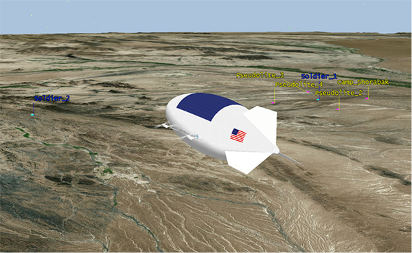
I leave you once again with our Afghanistan scenario, from the point of view of a high-altitude airship at 18,000 meters.
Figure 11. High-altitude platform, potentially carrying a pseudolite at 18,000 m. (Image: Michael Jones)
General Dynamics Mission Systems has introduced its HOOK3 combat survival radio.
The HOOK3 radio is 30 percent smaller and 40 percent lighter than the HOOK2 radio, and has a smaller, longer lasting battery, the company said.
In addition, the embedded GPS module has 32 channels enabling a faster position acquisition time, more accurate position reporting and better performance under forested or densely vegetated areas or near structures.
The radio transmits encrypted GPS, user identification, situation reports and other critical information to rescue teams and aircraft in short bursts to reduce the risk of detection. The radio can also use multiple GNSS.
The new radio provides direct line-of-sight voice and encrypted two-way data communications to help combat search and rescue teams quickly and accurately locate and rescue downed pilots and isolated military personnel, the company added.
The HOOK3 was designed using feedback from military personnel who rely on a survival radio in emergency situations. The new radio automatically activates and securely transmits location data when specific G-Force or the presence of salt water is detected by the radio.
“General Dynamics has delivered more than 36,000 combat search and rescue radios to 36 countries over the past 30 years,” said Paul Parent, a vice president of General Dynamics Mission Systems. “These radios have helped save the lives of military personnel isolated or in harm’s way during a mission.”
“The HOOK3 provides military personnel in emergency situations a highly reliable, easy-to-use, secure radio critical to their successful recovery.”
The General Dynamics HOOK3 radio is interoperable with all HOOK2 family radios, Quickdraw2 and SATCOM base stations currently used by U.S. and international military personnel.
The HOOK3 is designed for coalition operations, and the user-friendly transceiver is software-defined, enabling new features, waveforms and software upgrades to be added as they become available.
L3 Technologies’ WESCAM division has received an order from Airbus Helicopters to provide 37 MX-15 electro-optical and infrared (EO/IR) imaging systems for installation on multiple fleets of H225M Caracal helicopters.
The systems will be installed in France before being delivered to two foreign governments for military deployment.
“This order expands L3’s international business base while creating a new market opportunity for our leading WESCAM products,” said Michael T. Strianese, L3 chairman and chief executive officer.
“L3 WESCAM is proud to have been chosen to supply its MX-15 systems, as it highlights our role as a trusted global supplier of advanced imaging technologies to the OEM marketplace,” added Mike Greenley, president of L3 WESCAM. “Additionally, it confirms that the highly specialized optics and leading technologies in L3’s systems continue to meet the needs of emerging mission portfolios, ranging from combative military to time-sensitive response and recovery operations.”
The first delivery of 19 units will support a variety of missions, including search and rescue, aeromedical evacuation and assistance and disaster relief.
The second delivery will provide a highly detailed, multispectral view of combat search and rescue, naval operations, medical evacuation and military transportation efforts to mission operators.
L3’s MX-15 can be configured with up to six imaging and laser payloads, each of which shares the highest level of stabilization. It incorporates a GPS receiver and antenna, with options available for a GPS time sync interface and GPS data interface.
Sensor options include a high-definition (HD) thermal imager, color low-light continuous zoom, daylight step zoom spotter, day/night spotter, laser rangefinder and a laser illuminator. L3’s MX-15 can be found on additional models of Airbus helicopters, including the H125 and UH-72A.
L3 WESCAM serves all segments of the airborne, land and maritime markets with advanced EO/IR imaging and targeting systems (MX-Series) and modular system solution kits (MatriX).
MX-Series turrets are operational across 74 countries and on more than 137 different types of platforms, and are supported by more than 14 globally deployed authorized service centers and a team of field service technicians who are available for dispatch 24/7 to anywhere in the world. L3 WESCAM is a unit of L3’s Sensor Systems business segment.
The government of Australia has launched the first $50 million Defence Cooperative Research Centre (CRC), announced July 6 by the minister for Defence Industry, the Hon Christopher Pyne MP.
The Defence CRC is a collaborative program that brings together academia, publicly funded research agencies and industry (particularly small to medium enterprises) to create an interlocking research and innovation capability focused on driving a Defence outcome.
The first Defence CRC will focus on Trusted Autonomous Systems to deliver game-changing unmanned platforms that ensure reliable and effective cooperation between people and machines during dynamic military operations.
“Existing autonomous and robotic systems that operate in the manufacturing and mining sector are effective in controlled environments, but not suitable for the uncertain situations in which Defence operates,” Pyne said.
“To be effective, Defence needs autonomous systems to be highly trusted, robust and resilient and this initiative will bring together the best researchers from industry and universities to develop the intelligent military platforms of the future.”
The CRC for Trusted Autonomous Systems will receive annual funding of $8 million with a maximum of $50 million over a seven-year period.
The CRC will be chaired by Jim McDowell, a businessman who has had an extensive career in the defence industry, and most recently at the University of South Australia.
“As Chair, Mr. McDowell will be responsible for leading the development of the research program and business plan and work with industry on transitioning the research results into capability outcomes,” Pyne said.
This is the first of several CRCs that the Australian government is announcing. Further CRCs will be established on projects also aligned with priorities in the country’s Next Generation Technologies Fund.
Defence will be a member of each CRC along with universities, research agencies and industry. Participating members will be selected on the basis of their research excellence and technology expertise.
“The CRC environment offers excellent synergies for Defence, industry and universities to collaborate closely on Defence innovation,” Pyne said.
The CRC is an initiative of the Next Generation Technologies Fund which complements the Defence Innovation Hub as the two core initiatives of the new Defence Innovation System outlined in the Government’s Defence Industry Policy Statement. These two signature innovation research and development programs, together with the Centre for Defence Industry Capability, deliver on the Government‘s $1.6 billion commitment to grow Australia’s defence industry and innovation sector.
Contributing Editor Tony Murfin is on vacation this month. In place of his column, we bring you an advance look at an important UAV show as applied to surveying and mapping, and a story about drone use in surveillance.
In the zone
Legal issues, international market analyses and best practices will take center stage at the Interaerial Solutions Expo (IASEXPO), which will take place Sept. 26–28 in conjunction with Intergeo 2017 in Berlin, Germany.
At IASEXPO, the international UAV sector will be demonstrating the potential for civil and commercial UAV applications. IASEXPO will consist of an exhibition, forum and the FlightZone for UAV demonstrations. About 150 providers from 25 countries are expected to represent the young drone market at the IASEXPO.
IASEXPO’s practical forum will cover the latest topics with renowned experts. Visitors don’t have to walk far to switch between market overviews and expert presentations. The aim is to efficiently combine the trade fair and talks.
IASEXPO Forum 2016.
Regulations. As Germany’s drone regulations come into force this year, the legal aspects of using and operating UAVs is a key focus of the practical forum. Multicopters and drones weighing more than two kilograms can now only be flown in Germany by someone who holds a “drone driving license.” Pilots will be able to take the drone license test at the trade fair.
Frank Wichert from project management company procow will detail the requirements and reveal the precise procedure that pilots must follow. Speaker Ulrich Dieckert is a lawyer and expert on the approval process; he specializes in exceptions to operating bans that hinder drone work.
Market prospects. Kay Wackwitz, CEO of Drone Industry Insights, will present economic analyses of application opportunities and limits for UAVs, and discuss market developments and collaborations.
UAV Issue Manager Ralf Heidger from German traffic control (DFS) will discuss how DFS tackles the challenge of drones in the air space and tracking them within the air-traffic-management system.
Best practices. First-hand reports will provid examples of best practices in using drones for surveying and inspecting buildings and industrial complexes. Friedrich Wilhelm Bauer from Hannover University of Applied Sciences and Arts will highlight use of thermal-imaging technology for inspections. Benjamin Federmann from Aibotix-Leica will discuss the economic benefits of using drones in surveying and construction.
The German Association of Copter Pilots will weigh the question of whether to “make or buy” needed drones and services. Answers come from success stories in niche segments such as 3D modeling and smart framing. Maik Neuser from Westnetz and Carlo Zgraggen from Aeroscout will discuss inspections in the energy sector.
Other topics will be the use of drones in agriculture, forestry and disaster relief. Antoine Cottin from Carbomap and Bobby Vick from Precisionmapper will speak to the practical forum on drones used for surveying forests.
Drones on patrol
UAVs will soon be a common sight over border zones, crime hotspots and city streets in South Africa, as public safety and security officials and police departments discover the cost saving and efficiencies offered by drone patrol “armies,” according to Airborne Drones, a South African-based manufacturer of enterprise-grade drones.
Airborne Drones Vanguard 35-km long range surveillance drone ready to take flight. (PRNewsfoto/Airborne Drones)
Drones provide a solution to the limitations of other surveillance methods such as GPS tracking, CCTV camera observation, biometric surveillance and ground patrols. Aerial surveillance is increasingly being harnessed for security monitoring — traditionally, with costly helicopters. Drone surveillance present an faster and cheaper method of data collection.
Specialized security drones can enter narrow and confined spaces, produce minimal noise, and can be equipped with night-vision cameras and thermal sensors, allowing them to provide imagery that the human eye is unable to detect. In addition, UAVs can quickly cover large and difficult-to-reach areas, reducing staff numbers and costs, and don’t require much space for operators.
Autonomous, long-range security drones are at the vanguard of new policing methods, accoring to Airborne Drones. “Offering live video feeds to ground control stations, these drones can range autonomously over pre-programmed flight paths for extended periods of time, allowing for ongoing routine patrols across wide areas such as borders, maritime regions and high security installations.
Should an incident be detected, ground crews can then follow objects or intruders from a safe distance, providing visual support to safety and security teams. UAVs can provide detailed visual documentation of sites, enabling effective analysis, risk management and security planning.”
Around the world. Numerous countries are rolling out security drones to support public safety and defense initiatives”, says Airborne Drones. Israel has long harnessed advanced drones for military surveillance, and recently sold a fleet of “spy drones” to the Irish army.
The U.S. FBI has used drones for surveillance and tracking for several years. In Australia, the new $50 million Defence Cooperative Research Centre will develop long-range drones, automated vehicles and robots to help Australian soldiers fight the wars of the future. India is looking to military-grade UAVs for maritime and other surveillance and intelligence gathering.
In June, Brazil’s São Paulo became the first Latin American city to use drones for public security surveillance, and in July, Hamburg, Germany, deployed surveillance drones for the estimated 100,000 demonstrators at the G20 summit. In Australia’s New South Wales, the authorities are using helicopter and drone surveillance along the coast to protect holiday-goers from rip currents and sharks.
UAVs are also instrumental in managing transport infrastructure safety and security and event security, from event security infrastructure to spectator and crowd control and safety, to overall health and safety planning.
In my April column, I introduced the basic concepts behind GPS anti-jam technology, along with a bit of history around its evolution. I knew this was a popular topic, but I didn’t anticipate the enormous amount of positive correspondence I’ve received since, including many inquiries about where to buy this technology and who is entitled to have it.
So this month we return to the controlled reception pattern antenna (CRPA) topic, to look specifically at the major suppliers of GNSS anti-jam technology in a bid to help you select the best fit for your requirements.
As mentioned in April, CRPAs can trace their roots back to military radar developments in the 1970s and 1980s. It’s no surprise, then, that the main players in the CRPA market tend to be large defense primes. But there are many smaller companies, universities and research institutions that also play in the CRPA arena these days.
What about export?
When GNSS jamming was a little-known military problem, the situation was simple: anti-jam was a military technology for military applications only. Later, as GPS evolved into a dual-use technology, critical infrastructure and civilian applications brought a new demand for anti-jam in non-military domains.
Confusion then abounded about who exactly is entitled to make use of anti-jam technology. There are two distinct factors here: security classification, and export control. Let’s clear these up.
Security classification is simple: If a product is classified, it is only available to customers who hold the appropriate level of security clearance. Usually it is the performance and vulnerabilities of a product that would attract a classified status. As you might expect for in-service military products, the military would not wish everyone to know the performance and weaknesses of its deployed technology. This is why many datasheets for CRPAs omit performance information.
The second issue is export control. This, of course, varies by country. In the U.S., a CRPA developed towards a defense program is likely to have International Traffic in Arms Regulations (ITAR) restrictions attached to it. In Canada, CRPAs are subject to the Controlled Goods Program. In the UK, CRPAs sit on the “dual-use” export control list, which recognizes that CRPAs have both military and non-military application. An export license is usually required.
Before I go any further, a little disclaimer: I am not making any product recommendations in this article. There are many things to consider when choosing anti-jam technology, and you should always consult a navigation warfare expert and carry out appropriate evaluations prior to choosing a product. You should also seek guidance from your own government regarding any restrictions on export or import.
With that out of the way, let’s look at the offerings of a few suppliers. This is by no means a complete list, but I did manage to catch up with a few of the major players to ask them about their anti-jam technology offerings.
NovAtel
I spoke with Peter Soar, business development manager, Military and Defence, at NovAtel about NovAtel’s offerings.
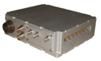
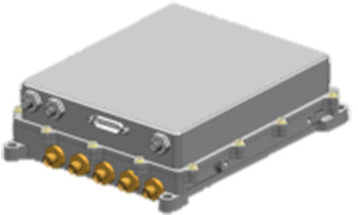
Peter Soar: “The GAJT-710 series are retrofittable GPS anti-jam products that combine a seven-element controlled reception pattern antenna (CRPA) and the antenna electronics in a single unit. The GAJT-AE-N is a GPS anti-jam antenna electronics system that supports a separated four-element antenna.”
Photo: NovAtel
Photo: NovAtel
Photo: NovAtel
Main features: “All three products protect the GPS L1 and L2 bands simultaneously, and are suitable for military (SAASM) receivers as well as open-signal receivers, normal civil receivers and ‘survey grade’ receivers. The wideband design means that the units are ready for M-code. In the GAJT-710, there are seven antenna elements for up to six independent nulls on both frequencies, and the GAJT-AE-N supports four antenna elements, for up to three independent nulls. All products use space-frequency adaptive processing for increased degrees of freedom. System messages provide an indication of jamming presence, even when the nulling is defeating the jamming.”
Intended market: “GAJT-710ML is optimized for land use, while GAJT-710MS is used for maritime and littoral applications. Both types are currently in use on mobile platforms and fixed installations. The GAJT-AE-N is optimized for smaller platforms such as unmanned air vehicles, and is currently in use on a variety of platforms. GAJT products have been shipped to customers in 16 countries to date.”
Example customers: “The GAJT-700ML (a predecessor to the 710ML) was selected for trials by the Canadian Army through the Build in Canada Innovation Program, with exercises performed on the Artillery Observation Post Vehicle (LAV III OPV). Both GAJT variants were selected for field testing by the U.S. Army Communication-Electronics Research Development and Engineering Center (CERDEC) through the U.S. Army Rapid Innovation Fund. The United States Naval Observatory (USNO) selected the GAJT-710ML to satisfy a requirement at sites throughout the Department of Defense Information Network (DoDIN). The GAJT-AE-N is deployed on the Schiebel Camcopter S-100, and was also selected for testing on the M777C1 Howitzer by the Canadian Army.”
Situation with regards to export: “All GAJTs are designed and built in Canada. As such, they are subject to the Controlled Goods Program of Canada, but they are free from ITAR for non-U.S. customers.”
Raytheon UK
Some Raytheon products were mentioned briefly in the April column; I caught up with Alan Wright, business development executive, Force Protection, to get the latest information.
Alan Wright: “Raytheon UK offers a range of anti-jamming products ranging from high-performance products with multiple-element CRPAs to low size, weight and power products. Our current product lines utilize either analog or digital technologies to suit specific end-user requirements.”
Product
Image
Key Features
GAS-1
Analog technology, 7 antenna elements, switchable L1/L2 protection, minimal quiescent time delay, nulling, J/N, M-code signal bandwidth, AE/antenna integrated variant, fiber optic output variant.
Digital technology, 5 antenna elements, simultaneous L1/L2 protection, low size, weight & power, STAP, nulling, J/N, direction finding, anti-spoof, jamming flag, M-code signal bandwidth.
Landshield
Digital technology, integrated 4-element antenna, simultaneous L1/L2 protection, low size, weight and power, STAP, nulling, J/N, direction finding, anti-spoof, jamming flag, M-code signal bandwidth, switched antenna variant.
MiniGAS
Analog technology, integrated 4-element antenna, simultaneous L1/L2 protection or L1 with L2 passthrough, low size, weight and power, minimal quiescent time delay, nulling, jamming flag.
MicroGAS
Analog technology, integrated 2-element antenna, simultaneous L1/L2 protection, very low size, weight and power, minimal quiescent time delay, nulling.
Intended market: “With over 25 years’ experience, Raytheon UK is a world leader in the development, production and supply of GPS Anti-Jamming (GPS-AJ) systems to the majority of the world’s military forces (including the U.S. DoD and UK MOD), with solutions developed and certified for air, maritime and land applications. Raytheon UK has designed and manufactured in excess of 10,000 GPS anti-jam units for the worldwide market.”
Situation with regards to export: “GAS-1, ADAP and SAS are subject to U.S. ITAR restrictions. Landshield, MiniGAS and MicroGAS are free from ITAR and subject to UK export control.”
Rockwell Collins
I spoke with Al Simon, business development for navigation products/solutions, to get the latest on Rockwell Collins’ offerings. Rockwell’s portfolio includes some CRPA products aimed specifically at weapons. Al kindly provided the following table to summarize:
Product
Image
Platform
Key Features
Integrated GPS Anti-Jam System (IGAS)
Weapons (Embedded)
GPS receiver + AJ, nulling and beamforming, spatial, 20 in3, <2 lbs, up to 4 RF antenna inputs, 90+ dB J/S performance *, GPS (simultaneous L1 & L2), path to M-code
Strategic Anti-Jam Beamforming Receiver (SABR)
Weapons (Embedded)
GPS receiver + AJ, nulling and beamforming, STAP, 46 in3, <3 lbs, up to 7 RF antenna inputs, 120+ dB J/S performance*, GPS (simultaneous L1 & L2), path to M-code
NavStorm+
Weapons
Nulling, spatial, 6.9 in3, <.6 lbs, up to 5 RF antenna inputs, 20,000 G shock, 90+ dB J/S performance*, GPS (simultaneous L1 & L2), path to M-code
NavFire
Weapons
Nulling, spatial, 2 in3, <.2 lbs, 1 or 2 RF antenna inputs, 25,000 G shock, 85+ dB J/S performance*, GPS (L1 or L2), path to M-code
DIGAR-200
Airborne, Maritime, Ground
Nulling and beamforming, spatial, 218 in3, <11 lbs, up to 7 RF antenna inputs, 110+ dB J/S performance*, GPS (simultaneous L1 & L2), path to M-code
DIGAR-300
Airborne, Maritime, Ground
Nulling and beamforming, STAP/SFAP, 69 in3, <5 lbs, up to 7 RF antenna inputs, 125+ dB J/S performance *, GPS (simultaneous L1 & L2), path to M-code
Small Platform AJ (Pre-Production)
Ground, Airborne
Nulling and beamforming, STAP/SFAP, 45 in3, <3 lbs, up to 7 RF antenna inputs, 95+ dB J/S performance*, GPS (simultaneous L1 & L2), path to M-code
STAP (Space Time Adaptive Processing); SFAP (Space Frequency Adaptive Processing)
* Beamsteering mode. Actual performance is classified
Situation with regards to export: All listed products are unclassified, but are subject to U.S. ITAR restrictions.
Roke Manor Research
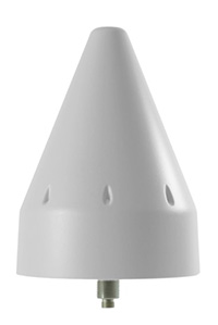
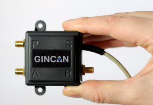
This column wouldn’t be complete without a few words on my own organization. Roke has been developing anti-jam CRPAs since the 1980s, but rarely offers its own products. Typically Roke develops bespoke anti-jam and anti-spoof technology for other defense organizations, including for some products already listed above. Examples of bespoke developments for more specialist markets include Gincan and the Helium antenna.
Photo: Roke
Photo: Gincan
Main features: Both these products are aimed at the commercial civilian market, but do also have defense interest. The Gincan is a very basic low-cost CRPA, with just two antenna elements. The Helium is a conical spiral design, using four antenna elements, and is primarily aimed at protecting GNSS in critical infrastructure. The Helium has excellent low-elevation performance. Both antennas feature very low latency, making them particularly suitable for timing receivers.
Intended market: The Gincan is primarily aimed at providing a basic level of anti-jam capability to the automotive mass market, including cars and trucks, but also has been adopted by some lightweight UAV platforms. The Helium is aimed directly at timing receivers for critical infrastructure, including mobile base stations, digital TV networks, stock exchange and financial institutions, and power and utility grids.
Example customers: Gincan has been delivered to 42 countries, with a mixture of commercial, defense and national security customers. Helium is a relatively new product, and is being trialed on infrastructure in two countries.
Situation with regards to export: Both products are unclassified and suitable for commercial use. They are subject to UK export control as dual-use items, and are ITAR-free.
Others
There are many other suppliers of CRPA technology — unfortunately, too many to cover in this column. Mayflower Communications offer a good range of CRPA products in the form of their NavGuard range. Some other suppliers include Cobham Antenna Systems, BAE Systems Rokar, Thales, Harris Corporation, L-3 Interstate Electronics and Lockheed Martin. I encourage you to contact these companies for the latest information if you are contemplating a CRPA product. If you’re a CRPA supplier and I’ve missed you, please feel free to post a link to your products in the comments section below.
So, that was a bit of a whirlwind tour through some of the products currently around. CRPAs come in all shapes and sizes, and they all have their own particular characteristics and subtleties.
I conclude by reiterating my earlier point. Always conduct a threat analysis, seek the help of a navigation warfare expert if necessary, and properly evaluate your choices. Happy choosing!
A drone that weighs less than 50 pounds can provide fully functional 4G cellphone service.
Virginia-based Fenix Group has partnered with Martin UAV, a Texas-based manufacturer of rugged utility drones, to launch an under-55-pound drone capable of providing fully functional 4G cellphone service.
While Fenix Group plans to issue its first production units to the U.S. Department of Defense and first responders, it anticipates demand from telecommunications providers, oil and gas companies, and crisis response units worldwide.
It also could mean connectivity in remote parts of the world.
In addition to providing a coverage area on the ground, the payload is also able to stream encrypted video from the drone’s camera system to anyone on the network. In the future, soldiers, search and rescue teams, and first responders will have access to drone video from their phones.
The Fenix team also enabled Internet access so that command centers could access the feed from anywhere in the world.
You’ve probably heard of at least one of those terms in any discussion around GPS anti-jam technology for defense.
Because they are all terms that describe essentially the same thing: a specialized antenna that helps protect GPS receivers from interference and jamming.
But what exactly are they? Where did they come from? How do they work? What comes next? Read on and find out.
A bit of history
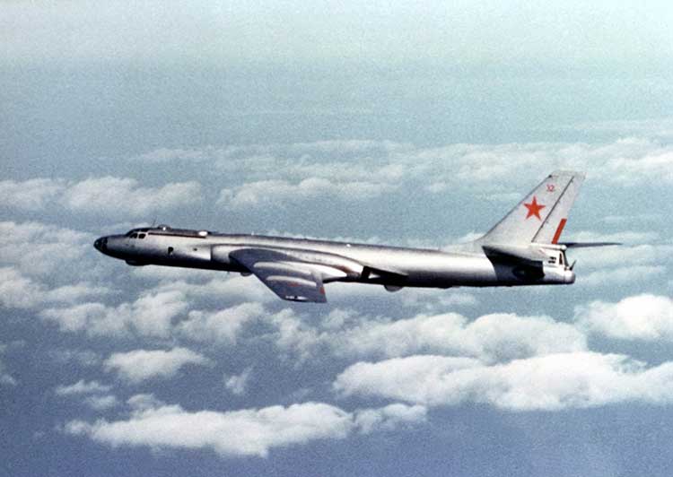
Let’s go back to the Cold War era, at a time when Soviet and Western states were continuously battling for electronic warfare (EW) superiority. In the early to mid-Cold War, radar jamming was the name of the game. Soviet aircraft, such as the TU-16 Badger and its derivatives, carried a range of EW equipment, including some very high-power jammers designed to interfere with radar systems.
Figure 1: TU-16 Badger, an important Soviet electronic warfare platform during the Cold War (Photo: Wikipedia)
Fast forward to the latter years of the Cold War, and we reach the era when the U.S. was busy developing the exciting new GPS system. The Department of Defense (DoD) wanted to ensure that a robust and accurate global navigation system was available to the military, and so the Navigation System with Timing and Ranging (NAVSTAR) launched its first satellite in 1978, eventually becoming the fully operational GPS system by 1993.
Magnificent and ground-breaking though it was, it was recognized very early on that GPS relied on very low-power satellite transmissions, and would be vulnerable if someone tried to interfere with it. Given the prevalence of high-power jamming during the still-ongoing Cold War, there was concern that, if an adversary knew about GPS, they could easily render it useless in a given operational area.
And so it was that the CRPA came to the rescue.
Enter the CRPA
Once again, this GPS anti-jam technology finds its roots in the Cold War, and specifically in radar technology, where engineers developed clever ways to ensure their radars could continue to operate in the presence of jamming. Sidelobe cancellation (SLC) was a well-established technique in the radar community, where a received jamming signal could be “cancelled” by combining the outputs of more than one antenna in the right way.
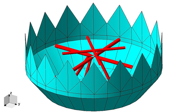
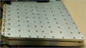
So, it didn’t take long to adapt this radar anti-jam technology to the problem of GPS protection, and the CRPA was born. At this point I must declare a modicum of national pride, as the earliest operational GPS anti-jam unit that I know of was British. The Plessey PA 9800 GPS Anti Jam Unit was built at Roke Manor in 1984, and tested in the U.S. at the Yuma Proving Ground, Arizona, in 1985.
This pioneering technology could defeat up to three simultaneous jammers in the shown configuration, but was modular in construction, allowing further channels to be added for handling higher numbers of jammers. And all of this in 1984, in the UK, for a U.S. military navigation system that wasn’t even fully operational yet. Incredible.
From then until the present day, CRPAs have seen continual interest and development as the technology of choice to protect GPS from jamming. So how do they work?
Theory of operation
A CRPA is attractive, because it doesn’t require you to make any changes to the GPS receiver itself: It simply replaces the existing antenna. CRPAs are generally larger than typical GPS antennas, because they contain a number of antenna elements, and some associated electronics to do the clever stuff.
There’s nothing magical or mystical about the basics of CRPAs: It’s just standard theory from your favorite textbook on adaptive signal processing. But, as ever, the devil is in the detail — how to make them work well in practice is more involved. And as the technology is generally export-controlled, I shall leave out the important in-depth details.
CRPAs work by exploiting spatial diversity; that is, making use of the fact that the desired satellite signals, and the unwanted jamming signals, generally arrive from different directions. In simple terms, you create a spatial filter, one that removes signals that arrive from particular directions, whilst letting through signals from other directions. To achieve this, rather than use a single antenna, we use an array of antenna elements.
Let’s think in simple and intuitive terms about how this works. Take a look at Figure 3. Here we have a primary antenna P, and some auxiliary antennas A1, A2, and so on. A signal arriving from the direction shown impinges on antenna A2, and slightly later it arrives at A1, and later still it arrives at P. For the sake of argument, if the signal is a simple sine wave, you will then find that the output from each antenna is that same sine wave, but with a different phase shift depending on the spatial arrangement of the antennas.
Now, let’s consider what we call the “weights,” which are labeled as w1, w2 and so on. Each of the weights, in this case, is simply a phase shift that we can define. By careful choice of weights, we could choose to make each of the antenna outputs align perfectly in phase, and then, when we sum all the outputs together as shown, we end up with a bigger version of the input signal.
This is what we would like to achieve if the signal was a satellite. We “steer” maximum overall antenna gain towards that satellite. This is typically what is meant when we refer to “beamforming;” It means steering maximum antenna gain towards a satellite.
Conversely, we could also choose the weights to have the opposite effect: to minimize or completely cancel out the signal. This, of course, is what we would like to do if the signal was a jammer, and is referred to as “nulling” or “null-steering.”
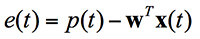
Figure 3. Adaptive antenna basics.How do we determine what those weights should be? Well, this is where your standard theory in adaptive signal processing comes in. Let’s say the objective is to minimize the jamming power out of the antenna. We can write the output power of the adaptive antenna as:
Figure: Michael Jones
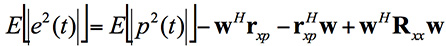
The average output power can be found by taking expectations:
Figure: Michael Jones
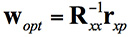
Taking the minimum and rearranging this leads to the well-known Wiener equation:
Figure: Michael Jones
This Wiener equation is the one to remember. It says that the optimum weights can be found by taking the inverse of the data covariance matrix, and multiplying it by the vector of cross correlations between the primary and auxiliary antennas. As in any adaptive signal processing problem, a simple way to solve the Weiner equation and get the weights might be to use your favorite gradient descent algorithm, such as least mean squares (LMS):
Figure: Michael Jones
However, a solution using this approach does have its problems, for reasons beyond the scope of this article. The mathematics of beamforming are also bit more involved, so I’ll leave that out here.
Rather than the grossly simplified diagram used here, most decent CRPAs also use a more complex architecture based on space-time adaptive processing (STAP) or space-frequency adaptive processing (SFAP). This generally allows much higher levels of jammer cancellation against a wider range of threats.
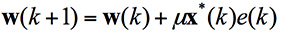
To finish off this whirlwind section on CRPA basics, let’s see what some example antenna gain patterns might look like. In the figures below, the blue line represents the direction of arrival of a GNSS satellite signal, whilst the red lines indicate the direction of arrival of a jammer. In the first diagram we have a single jamming signal: the antenna gain pattern is a nice hemisphere, as we would generally like, but there is a nice deep null in the direction of the jammer. Moving on to the next diagram, we can see the effect of having three simultaneous jammers on the same CRPA: again we have nice deep nulls in the direction of each jammer, but we are starting to lose more of the sky, and we may start to lose the odd satellite as a consequence. Finally, we have an example of beamforming on a single satellite, whilst nulling out a jamming source.
Again, it’s beyond the scope of this article, but the layout of the antenna elements plays an enormously important part in the performance and behavior of the CRPA.
Figure 4. Illustrative beam patterns of a CRPA antenna in the presence of jamming. (Figure: Michael Jones)Figure 4: Illustrative beam patterns of a CRPA antenna in the presence of jamming (Figure: Michael Jones)
Operational Anti-Jam Units
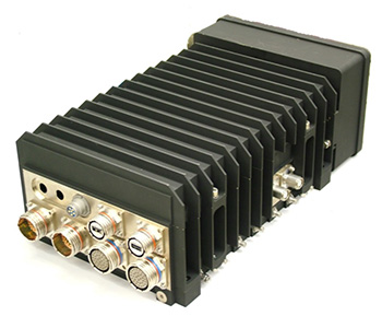
With some images courtesy of my friends at Raytheon, let’s look at a few examples of deployed military CRPA hardware over the years.
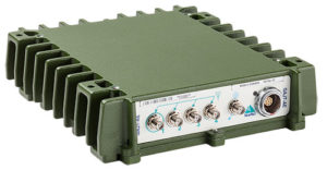
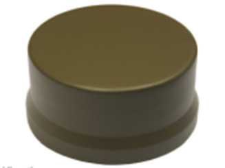
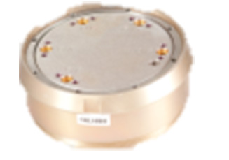
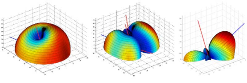
The GAS-1 system entered service in the U.S. in 1997, as a replacement for the earlier AE-1 (1990 to 1996). The CRPA is composed of two parts: the antenna array, which is a seven-element layout, and the antenna electronics as a separate box. The GAS-1 was incredibly successful and became the de facto standard anti-jam technology, fitted to air and sea platforms around the world. Even today, 20 years after its launch, it continues to be fitted to many platforms.
Figure 5. GAS-1 CRPA. (Photo: Raytheon)
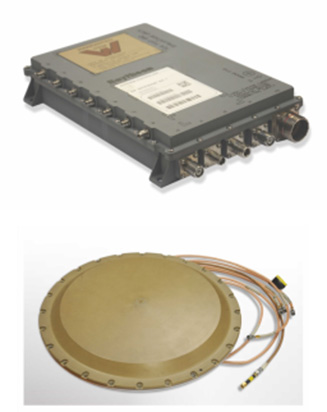
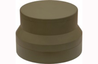
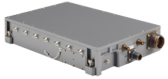
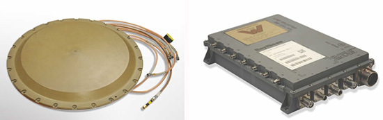
By the late 1990s and early 2000s, the Navigation Warfare (NAVWAR) program was in full swing, and the military was looking for enhanced protection against evolving jamming threats. The U.S. initiated a program called Advanced Digital Antenna Production (ADAP). The ADAP product, launched in 2006, was a direct form-fit replacement for the analog GAS-1 system, and introduced a number of advanced features. Most notably, the ADAP simultaneously protects both the L1 and L2 frequency bands, and utilizes STAP processing to achieve high levels of wideband jammer cancellation.
Figure 6. ADAP Digital CRPA. (Photo: Raytheon)
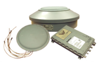
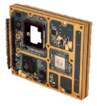
In parallel with the ADAP development, the Digital Antenna Control Unit (DACU) was different in a number of ways. Firstly, it was a true beamforming solution, allowing simultaneous antenna beams to be steered toward satellites, whilst simultaneously nulling out jammers.
Secondly, it was tightly integrated with the GPS receiver, with the GPS receiver hardware located in the same unit.
Thirdly, the DACU was able to perform a number of other advanced functions, such as direction-finding of interference sources. Interestingly, the DACU was used to help locate the source of the interference at the notorious Newark airport jamming incident in 2009.
By the mid-2000s, CRPA electronics were pretty mature and well-understood. The electronics had been miniaturized, and pretty much everything was put onto a single chip. But the physical size of the antennas persisted as a problem for some platforms requiring low size, weight and power (SWAP).
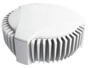
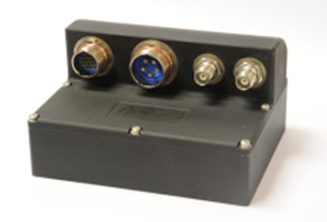
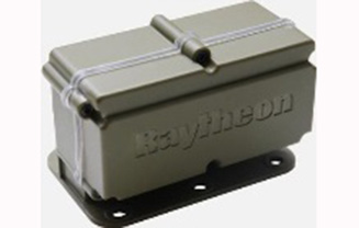
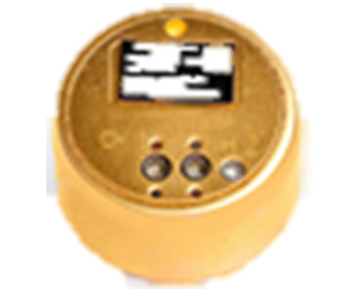
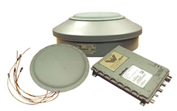
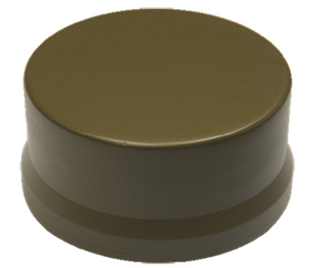
The Landshield, launched in 2014, was a step-change in CRPA technology. Not just because it was a small and fully self-contained unit (about the size of a hockey puck), but because it was the world’s first CRPA to include true anti-spoofing capability.
Figure 8. Landshield Advanced CRPA with Anti-Spoof Technology. (Photo: Raytheon)
Blurring the lines between military and civilian
Going back a few years, the military was heavily focused on CRPAs and anti-jam techniques in general. Military GPS receivers had been developed and deployed, and the question was how they could retrofit robustness to them. At the same time, the commercial world was heavily focused on mass-market GPS receivers — reducing cost, increasing performance — with little care about jamming.
If you’d talked to me five or six years ago, I would have said the military sector is 20 years ahead of the commercial sector in anti-jam technology, and the commercial sector is 20 years ahead of the military sector in receiver technology.
This assertion holds far less true these days; the lines of separation are much more blurred. The military is learning from the commercial world, embracing COTS, and developing new GNSS receivers. Conversely, civilian applications are now much more concerned with jamming, leading to the adoption of low-cost CRPAs in non-military applications.
The future of the CRPA
Where will CRPA technology go from here? We’ve already seen that the latest generation of CRPAs now performs anti-spoofing, as well as anti-jamming. But there is plenty more to see yet.
Although the core technology behind CRPAs is now mature, the trend for the future will be about “doing more with less.” CRPA technology will become more of a multi-function system. Military platforms need to cut down on the number of separate systems they install, and so CRPAs are likely to become multi-functional, performing situational awareness and signals intelligence.
As antenna technology progresses, we will likely see protected navigation solutions utilizing the same hardware as communication systems and radar systems, providing CESM and RESM functions, and being part of an integrated electronic warfare suite. And conformal antennas will see a resurgence of interest for complex and space-constrained platforms.
Assessing the health of an entire industry is not an easy task, but talking with industry leaders and looking for examples of growth and investment can help. My inquiries have led to discussions with General Atomics, Association for Unmanned Vehicle Systems International (AUVSI), Aeryon Labs and SensoFusion. Further viewpoints welcome; see the conclusion of this article.
Discussions included questions around these issues:
The level of maturity of common technologies in use on UAV platforms and systems
The level of maturity of integration of those technologies
A sketch portrait of the industry
Rough numbers or percentage of small players versus large ones
The rate of consolidation of companies: Has it happened, or has it yet to happen?
The financial underpinnings of the market: Does it have legs to go the distance?
If we start with a top-level overview of the industry, we find on the commercial side an industry trying to figure out what it is and who its customers might be. But a well-established military segment is quite mature. A large number of multi-rotor UAV suppliers use simple handheld controllers, all aimed at different applications where they are seeking a niche. The FAA’s release of regulations last year for use of small unmanned vehicle systems (sUAS) has provided a real boost to many more commercial pay-for-service ways these vehicles are now being used.
Multi-rotor UAVs are being put to use in surveying, filmmaking, newsgathering, real estate, crop and pipeline inspection, firefighting, law enforcement, security, search and rescue, and disaster monitoring and relief, just to mention a few applications. Of course, home and hobby flying your own drone in your backyard or open areas has fueled the Chinese DJI drone manufacturers’ growth significantly. While the FAA requires registration of private drones, this has not prevented an increase in commercial pilot reports of UAV incursions into controlled airspace, which appear to be on the increase.
Military Use. Then there are small, medium and large fixed-wing UAVs that appear to have been mostly developed for and used by the military. These include hand-launched surveillance drones for small groups of ground troops; mid-sized, longer range surveillance drones finding applications in commercial inspection; and the bigger GA Predator type aircraft that have become the U.S. military’s search and destroy long-range vehicle, which can carry significant ordinance.
At the top end, UAVs like Global Hawk are used for very high altitude, long-endurance surveillance. Finally, we have target drones like the Northrup Grumman BQM-74E, which earns its living pretending to be an enemy anti-ship cruise missile for the U.S. Navy.
Northrop Grumman’s BQM-74E Target Drone works for the U.S. Navy. (Photo: U.S. Navy)
Commercial Growth. Brian Wynne, president and CEO of the Association for Unmanned Vehicle Systems International (AUVSI), believes for the commercial segment that, “The UAS industry is primed for incredible growth. UAS are being used in all 50 states by industries like real estate, agriculture and the oil and gas industry for more than 40 different types of business applications, including aerial photography, emergency management and utility inspection.”
More than 500,000 people have registered their UAVs with the FAA in the U.S., and around 20,000 of those are looking to start commercial operations. AUVSI expects more than 100,000 jobs will be created when UAS are integrated into and allowed to operate in the U.S. National Airspace System (NAS).
AUVSI analysis of initial UAS applications. (Source: AUVSI)
However, Wynne went on to comment, “This this can only happen if the government puts in place a true, holistic plan for full UAS integration that includes flights over people, as well as beyond line-of-sight operations, access to higher altitudes and platforms above 55 pounds.” AUVSI estimates that in the first decade after full UAS integration into the NAS, these commercial operations could generate more than $82 billion is economic impact.
Even before the FAA’s release of formal regulations (known as Part 107) for use of sUAS in June 2016, more than 5,500 businesses received approval to fly for commercial purposes. AUVSI published a report analyzing these applications: “Commercial UAS Exceptions By the Numbers” provides an overview of the developing commercial UAS industry in the U.S. (See auvsi.org/advocacy/exemptions70)
More than 90 percent of these businesses make less than $1 million in annual revenue and have fewer than 10 employees. This indicates that the engine behind this growth comes from small, independent business.
Nevertheless, big organizations such as CNN are also exploring visual line-of-sight operations over people and safely using UAS for newsgathering in populated areas, as part of the FAA’s Pathfinder Program. PrecisionHawk is testing extended visual line-of-sight operations in rural areas, aimed at precision agriculture, and BNSF Railway is testing beyond visual line-of-sight (BVLOS) operations in rural and isolated areas for the inspection of rail system infrastructure.
Anti-Drone Systems. More recently, anti-drone systems have joined the party to help defend against unwanted UAV incursions into secure areas already protected by conventional systems like radar, acoustic and optical detection systems. Secure areas include prisons, government buildings/facilities, utility companies (including nuclear power stations) and airports. Sensofusion in Finland is one such company with its Airfence, one of three anti-drone systems tested last November by the FAA at Denver airport. The other systems were supplied by CACI International and Liteye Systems.
The Airfence drone countermeasure platform can automatically detect, locate, track and take over UAV controls as well as locate the operator.
Kaveh Mahdavi, VP of Operations for Sensofusion, thinks that, relatively speaking, the UAV industry is quite mature — what’s still being developed are systems to enable autonomous drone flight. The regulations published so far only address ground-pilot-controlled operations, even though BVLOS testing is progressing well.
On the other hand, the maturity level of anti-drone systems range from proven to embryonic. As many as 50 companies with different technical solutions are vying to succeed in this new segment.
As the UAV segment continues to grow, so does the need for detection and prevention of drone incursions.
These systems employ three basic technologies: radar, optical and RF. Radar and optical need direct line of sight and cannot see over the horizon. That makes them quite short-range, and detection and defense has to be exceptionally quick to prevent unwanted UAV visits. The Airfence RF system is omnidirectional and can even detect UAS preparing for take-off up to six miles away, as demonstrated at the Denver airport.
Thus, intrusion warnings at a geofence distance of 3–4 miles can be generated, and automatic defense/prevention is readily achieved. Some utility companies want to have detection, warnings and control of intruder drones within a mile of their facilities.
Mahdavi described how Airfence uses a library of drone control RF signatures for all known UAS, with new signatures added regularly. The system can detect, intercept and directly take control of the offending vehicle.
During the Denver tests, Airfence initially only detected one third of the target UAVs, but the RF signatures of all targets were acquired.
Using remote engineering updates to the library, by Day Three all were detected. With lower prices, consumer drones are becoming a real threat for these sensitive areas.
The anti-drone industry will no doubt face considerable consolidation over the next couple of years, but Mahdavi feels that Sensofusion is well placed, with significant military and government business funding its growth — “securing the right contracts with the right customers,” as he says — without external investment.
Mature Company. General Atomics Aeronautical Systems Inc. (GA-ASI), makers of the well-known Predator, Reaper and other Medium-Altitude Long-Endurance (MALE) drone systems, has been in this business for almost 25 years. GA-ASI considers its products to be proven, mature and resilient for the military and government markets that demand them to be so. The company uses in-house products and technology across its range of air and ground systems.
SeaGuardian and SkyGuardian will be commercially certifiable versions of the Predator.
In an effort to align with European customer interest, GA-ASI has been investing in a certifiable version of the Predator-B, recently named SkyGuardian. A derivative for marine applications will be known as the SeaGuardian.
Just as military transport aircraft want to transit through civilian airspace and, in order to do so, have been equipping with certified navigation systems for a number of years, military drone operators want to be compatible with Europe’s high-density commercial flight regulations and to operate within existing air-traffic control corridors.
To arrive in time for these European programs, GA-ASI has invested to get ahead of the market. This has entailed assessment of all on-board and ground components, and has led to upgrades and redesigns where necessary.
“Nevertheless, on existing product lines, there is a large degree of commonality across common systems on multiple platforms,” said Mike Cannon, VP of international programs. Common systems include datalinks, avionics, de-icing systems, and some airframe components.
GA-ASI has developed and integrated its own flight control system in its aircraft for more than 20 years. This has proven to be a key element of the success for the Predator family of products. Because all these systems have been flying for so long, they have become proven elements of their unmanned systems.
Hughes Network Systems Defense and Intelligence and Systems Division (DISD) has been selected by GA-ASI to provide satellite communications on the type-certifiable Predator B remotely piloted aircraft (RPA) system. Working with GA-ASI, Hughes will customize the aircraft’s satellite communications system with modified Hughes HM series modems. The advanced modems will enable a significant increase in data transfer rates, using an enhanced waveform that ensures resilient and secure communications when operating in challenging environments.
Big Players. It is very difficult for new start-up companies to enter this top-level segment of the UAV market. It’s very expensive to develop, demonstrate and prove large airframes, control systems and avionics that customers can rely on. GA-ASI has a unique position alongside major suppliers such as Boeing, Northrup Grumman, Israel Aerospace Industries, and Lockheed Martin. However, viable Chinese UAS are beginning to show up in the marketplace, apparently as a result of significant, focused investment.
Nevertheless, with an enviable position as a major supplier of platforms used in multiple applications, with sufficient internal resources to fund initial vehicle developments, GA-ASI has secured a large number of programs with multiple follow-on orders and funding for increasingly more capable derivative UAS. As the company now looks toward the certifiable segment using another internally funded product launch, it is again reinforcing its leadership position in its chosen unmanned market segment.
Small Vehicles. Meanwhile, the world of small unmanned air vehicles (sUAS) continues to thrive, given the release of FAA regulations last year, and the blossoming of many commercial applications using increasingly capable small multi-rotor drones. David Koetsch, CEO and co-founder of Aeryon Labs in Ontario, Canada, thinks the sUAS segment is also quite mature.
Aeryon has been around for more than 10 years, so it has also had time to prove its platforms and internal systems. It also builds its own flight-control hardware and software, affording substantial power savings and longer endurance from automatically managing rotor speeds.
Aeryon Labs provides complete solutions, such as its SkyRanger sUAV partnered with AeryonLive Tools software.AeryonLive Tools software. by Aeryon Labs.
“The quad platform has been around since 1938, so the concept is hardly new; however, over the last decade, Aeryon Labs has substantially matured and ruggedized our platform, the Aeryon SkyRanger sUAS,” Kroetsch said.
The company’s focus is on not only on the UAV platform, but also in supplying complete systems meeting different customer needs. With electro-optical and thermal imaging camera payloads and an onboard georeferencing data collection/processing system, it provides integrated solutions such as AeryonLive Video and Telemetry and AeryonLive Fleet Management using real-time software tools.
For the oil and gas industry, providing compatibility for off-line flight planning software inputs and importing compatible aerial imagery into existing GIS systems is a significant feature. The SkyRanger UAS has benefited from many years of use in the field, and has been designed with modularity and ease of use with snap-on/off parts that make set-up and operating in bad weather a lot easier.
Aeryon’s business is currently 50% military, 25% oil and gas and 25% public safety (such as rapid traffic accident data gathering). Other entrants to these segments might find it easy to put together an unmanned system from parts bought on the internet; what comes considerably harder is proving reliability and interoperability with existing customer systems.
Actually, to develop an industrial-grade UAV takes lots of investment and requires experience gathered over many years. Customers have learned how to differentiate between those dabbling in the market and those with serious capabilities.
Consolidation. Consolidation is inevitable in this market segment — perhaps within the next six months, certainly over the next two years — because there are so many companies trying. Investment for these start-ups is getting harder to find, and it may be too late for most, as the leaders are already well established.
“It’s essential to pick a niche within the increasingly competitive UAV industry,” Kroetsch said. “This is why Aeryon chose early on to focus on enterprise-level offerings in commercial, public safety and military.”
Recall what happened to 3D Robotics. Even though 3D Robotics raised many millions in funding, its Solo quadrotor fell from grace, perhaps due to continuing design issues and being higher priced compared to rapidly declining DJI Phantom 3 prices. “Competition and consolidation look to be very similar to that which happened with digital cameras,” Kroetsch said.
For Aeryon, being Canadian appears to be an advantage, as U.S. export regulations seem to be handicapping U.S. drone manufacturers. Aeryon sells in 35–40 countries because its product does not contain military-restricted components and only uses commercial parts. Canadian regulations for drone system exports do not prohibit worldwide sales for such products, while U.S. regulations can be difficult for U.S. suppliers to negotiate.
Nevertheless, unexpected hurdles to adoption still exist, such as company policies related to health and safety, union restrictions, and potential internal clashes on responsibility for implementation. But with 100% test, and a hardened design for tough environments, Aeryon sees itself well positioned to grow in its chosen industrial sector.
Conclusion
This has been a brief overview of the UAV/UAS industry — a first try, if you will. Nevertheless, it’s a summary that we can use as a benchmark for where we are right now, and a departure point for future growth.
We have quite mature capability in both large and small UAS, with integration focused on flight-control and navigation systems. The larger UAS enjoy a relatively mature market with established suppliers of lower numbers of expensive systems, while the sUAS segment is larger, younger and less expensive, with fewer barriers to entry.
Nevertheless, the mature industrial segments with harder, more integrated requirements make it difficult for new entrants to climb the steps into more complex commercial operations. The recreational segment is dominated by DJI, and it remains strong with well-performing, easy-to-operate drones.
Because of the ease of access to smaller drones, despite FAA and other countries’ regulations, people seem to want to penetrate secure facilities like utilities, airports, military bases, prisons and other government locations. Therefore, anti-drone systems using optical, radar and RF are becoming available, and facilities are being equipped to prevent unwanted drone incursions.
AUVSI XPONENTIAL. In May, I’ll be roving the show floor at the XPONENTIAL show in Dallas, and I welcome your added insight, from all corners of the UAV industry. We will continue this assessment in an upcoming
Professional OEM + UAV newsletter column (subscribe free at gpsworld.com/subscribe).
OriginGPS has released its new ORG 4500 series, which is a fully-integrated product that supports ultra-compact applications for both GPS and GLONASS.
The ORG 4500, kin to the ORG 4400 series introduced in 2016, addresses the increasing demand for high precision with the smallest possible footprint, and takes the company’s ultra-small form factor to a new level.
OriginGPS ORG 4500 is designed for ultra-compact IoT applications such as wearables, smartwatches, clothes and pet trackers, drones, connected cars, and health testing and tracking devices.
“The newest GNSS product perfects the industry’s most comprehensive GNSS/GPS family of solutions,” said Haim Goldberger, CEO of OriginGPS. “Our modules readily resolve the industry’s acute pain points of unreliability and sensitivity in the commercial, engineering and defense sectors, enhancing the quality of experience and helping our customers remain competitive.”
OriginGPS offers a range of fully-integrated GNSS/GPS and antenna solutions, encompassing a wide gamut of standard and essential tools for navigation. The small form factor and high sensitivity of OriginGPS’s modules enable new business models, like “machine as a service,” and are suited for a variety of applications, such as wearables, like smart watches and pet tracking, as well as smart cities and drones.
OriginGPS modules are deployed around the globe in key sectors, such as transportation, civil engineering, precision agriculture and time reference.
Narrowband IOT platform. Ramping up the race to offer the best Narrowband IoT (NB-IoT) products, OriginGPS continues to expand its presence in the global navigation market with a steady stream of new IoT-enabled solutions, such as its recently released IoT platform (ORG 2100).
A key theme again at this year’s Mobile World Congress was the Internet of Things, with an additional focus on the challenges of ensuring interoperability of home and industrial applications. OriginGPS’s IoT Platform effectively removes usability challenges with a plethora of customizable sensors, such as temperature, pressure, accelerometer, light and humidity.
OriginGPS will showcase its range of mini + mighty GNSS/GPS modules at Embedded World 2017, Germany, March 14-17, hall 3, booth 121.