A roundup of recent products in the GNSS and inertial positioning industry from the December 2021 issue of GPS World magazine.
OEM
Satellite-cell terminal
With built-in GPS receiver
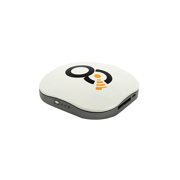
OQ Technology’s dual-mode satellite-cellular IoT modem and tracker is a plug-and-play, small, low-cost and low-power solution that can collect data from more than 1,000 sensors. It has a built-in GPS receiver and supports 5G NB-IoT, GSM, LTE-M and bi-directional satellite links. The flexible, robust and programmable dual-mode terminal has pre-paid data packages suitable for remotely monitoring and controlling fixed and mobile assets in industries such as transportation, oil and gas, utilities, and maritime.
OQ Technology, oqtec.space
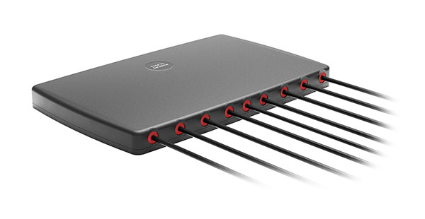
Fiber Extension
Provides mission-critical, extended length GPS over fiber
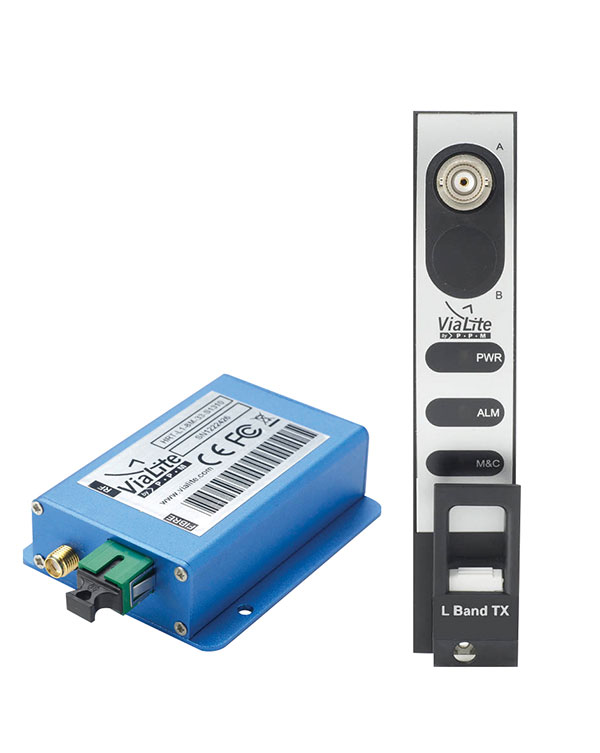
ViaLite’s GPS over Fiber Extension Kit for Microchip/Microsemi GPS timing servers provides mission-critical GPS timing and synchronization for systems requiring extremely accurate clock signals. Standard transmission distances for the extension kit can be up to 10 km, while solutions are available for distances as long as 50 km. The ViaLite kit was chosen for its unique performance with Microsemi’s S650 timing server. The ViaLite GPS link is designed to provide a remote GPS/GNSS signal or derived timing reference to equipment located where no signal is available, such as inside buildings or tunnels. By using optical fiber instead of traditional coaxial cable, extreme distances are possible with no radio frequency loss and zero introduction of noise.
ViaLite, vialite.com
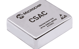
Edge Computing Device
Acts as a high-performance master clock
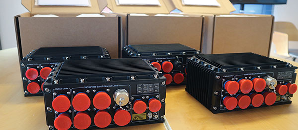
The RELY-MIL-TIME-SERVER, which complies with MIL-STD-810G and MIL-STD-461G, embeds the latest timing, networking and security technology in a single SWaP platform. The all-in-one rugged edge computing device acts as a high-performance master clock and serves secure accurate timing distribution (PTP, NTP, GNSS). The timing feature is combined with high-bandwidth and high-availability Ethernet switching and L2/L3 cybersecurity services in a unique commercial-off-the-shelf device. At its heart is a Xilinx Ultrascale+ MPSoC device powered by SoC-e hardware IP cores for PTP and high-availability low-latency Ethernet networking.
Relyum by SoC-e, www.soc-e.com
IMU
Provides improved attitude and vibration control
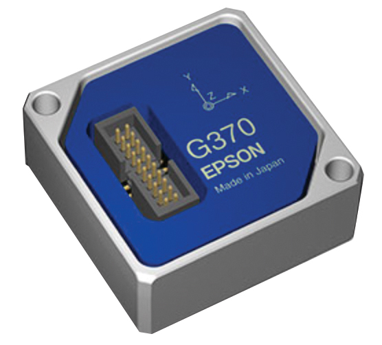
The M-G370PDS0 inertial measurement unit (IMU) is equipped with a high-performance six-axis sensor. It has an angle random walk (short-term variation in output) of 0.03°/√h, which is half that of its predecessor, and can more accurately detect very slight changes in the attitude of equipment and systems, since they do not get lost in sensor noise. The small size, light weight and low power consumption will help customers make their own products smaller and lighter. It also maintains compatibility with earlier products (the M-G370/365/364/354), making performance upgrades easy.
Seiko Epson Corp., global.epson.com
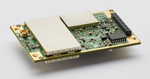
Timing Solution
Embedded module for third-party hardware

The OSA 5400 SyncModule enables technology suppliers to integrate precise synchronization into their hardware. Its M.2 form factor can add timing capabilities to switches, routers, open compute servers and other IT devices. The SyncModule provides GNSS, precision time protocol (PTP) and network time protocol (NTP) engines as well as comprehensive PTP and GNSS monitoring and assurance functionality. It can enable assured sub-microsecond timing in public and private networks as well as critical infrastructure. Featuring multiple interface options for easy integration, the OSA 5400 SyncModule comes with an open API. It also can be managed by ADVA’s proven Ensemble Sync Director management system.
ADVA, adva.com
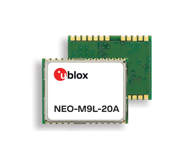
Evaluation software
For u-blox M10 GNSS technology integrators
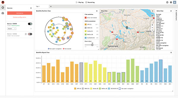
Running on Microsoft Windows, u-center 2 offers anyone working with 10th-generation (M10) u-blox GNSS technology a highly intuitive interface to configure GNSS products, evaluate their performance, improve the quality of their software, and experience the performance boost achieved using GNSS-related services. The software is the successor to the u-center GNSS evaluation software, which has been used by design engineers for almost two decades to develop GNSS receiver applications. Compatible with u-blox M10 GNSS technology, u-center 2 is designed to offer improved performance over its predecessor. New features in u-center 2 simplify configuration, evaluation and software development of GNSS-based solutions. It is free for download.
u-blox, www.u-blox.com
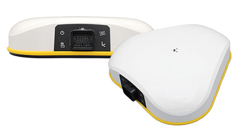
GNSS Antenna
Low profile for easy installation
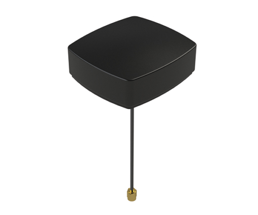
The MEA-1227-SM is a GNSS/L1 and L2 low-profile screw-mount antenna. It has high performance suitable for maintaining constant network connectivity. The MEA-1227-SM covers all GPS/GLO/BEI/ QZSS/Galileo/SBAS/L1L2 standard frequencies. It is designed for telematics systems, remote surveillance, asset tracking and any internet of things (IoT) system applications. This screw mount antenna is easy to install, with a low profile suitable for challenging installations. It has a IP67-rated housing and anti-rotation mounting.
Maxtena, maxtena.com
Transportation
E-Bike Guidance
Mapping and navigation for city riders

The Cowboy e-bike solution provides riders with high-performance, real-time GNSS accuracy, enabling them to map their own paths and those of the cities in which they live. It uses smart road-companion applications to ensure riders get precise information, regardless of the route they travel. The positioning component uses Taoglas’ Accura GVLB258.A, a multi-band GNSS L1/L5, high-performance stacked patch antenna, in conjunction with u-blox’s SAM-M8Q GNSS positioning module. The combination allows for extremely low power and high accuracy. The solutions works with “micromobility” services offered by Cowboy, such as Easy Rider for theft detection, bike insurance and crash detection notifications.
Taoglas, taoglas.com; u-blox, u-blox.com
Vehicle Tracking
Instant decimeter-level accuracy with automotive sensors
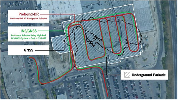
The Profound-IVT (instant vehicle tracking) provides cost-effective vehicle navigation. Based on a firmware library, and rapidly adaptable to any navigation platform, IVT combines precise point GNSS positioning (PPP), dead reckoning and radar technologies in an integrated solution to provide decimeter-level positioning accuracy plus orientation and velocity. IVT performs in tunnels, dense urban environments, multi-level highway junctions and parking garages. With errors <1% of distance travelled, resolution is extremely rapid. Base stations are not required and there are no operating range limitations. Applications include driver assistance, mobility and taxi, autonomous vehicles, geofencing, fleet tracking, insurance, driving and safety management, and connected driving.
Profound Positioning Inc., profoundpositioning.com
Surveying & Mapping
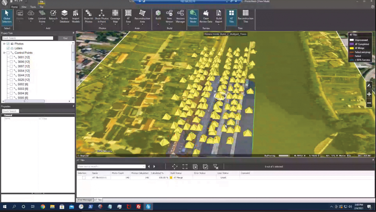
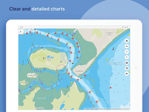
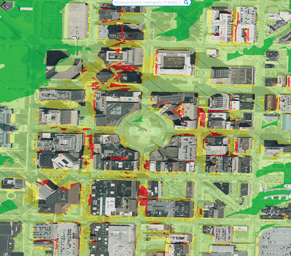
City Twins
Off-the-shelf map data through the HxGN Content Program

Metro HD city data is a new offering of ultra-high-resolution 2D and 3D digital twins of major cities. Metro HD expands the data stack to include high-definition true orthophotos, obliques, digital terrain models, lidar point clouds, 3D building models (LOD2), 3D meshes and land-use maps. Cities captured in 2021 include Munich, Cologne, Vienna, Milan, Amsterdam, Stockholm, Tokyo, Dallas, New York, Stuttgart and Frankfurt. More cities will be added in early 2022. The program uses a hybrid urban mapping sensor, the Leica CityMapper-2, that concurrently collects lidar and aerial imagery. The derived products, based on the strength of each subsystem, result in superior accuracy and temporal consistency across all three data dimensions.
Hexagon Geospatial, hexagon.com
GNSS + Laser
Workflow for Esri ArcGIS Field Maps
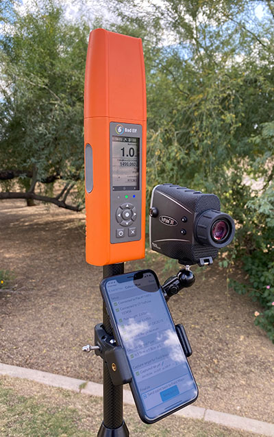
Bad Elf LLC and Laser Tech are providing an integrated laser offset workflow for acquiring high-accuracy field data in GNSS-challenged environments. The new workflow integrates Bad Elf and LTI hardware in collaboration with ArcGIS technology from Esri. The Bad Elf Flex GNSS receiver connects to any LTI TruPulse rangefinder over a wired or Bluetooth connection to deliver high-accuracy location data to Esri ArcGIS Field Maps. Field workers can now efficiently complete position and height data collection in access-limited situations, saving time, money and effort. The Bad Elf app workflow runs on Android and iOS.
Bad Elf, bad-elf.com; Laser Tech, www.lasertech.com; Esri, esri.com
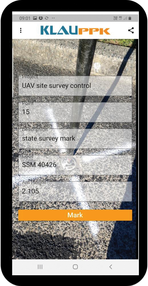
Survey Platform
Cloud based for collaboration

Geo-genie is a cloud-based collaborative and professional mapping and surveying platform enabling customization and creation of geocentric information systems. Teamed with Handheld’s Algiz RT8 rugged field tablet, it streamlines work and allows non-professionals to perform accurate geodetic mapping, guiding and monitoring of their data collection. The platform enables organizations to have an advanced, professional surveying and GIS platform with customized procedural workflows, management of user hierarchies, and integration with other organizational information systems. Geo-genie can connect with professional surveying equipment, such as GPS and total stations, and integrates data into a cloud-based central database with no restriction for specific data-collection hardware.
Handheld Group, handheldgroup.com; Geo-genie, Geo-genie.com
GNSS Amplifier
Marks forest, urban trees in logbook app
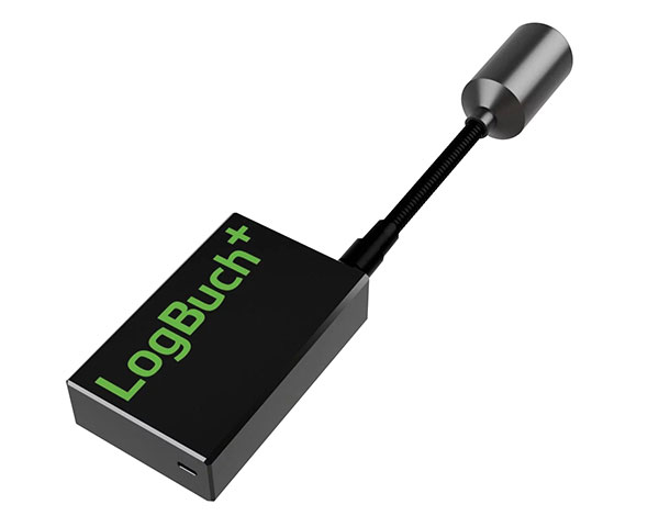
The wireless GNSS amplifier LogBuch+ increases the accuracy of location data with the cloud-based LogBuch application. The app enables voice-based digital mapping via a smartphone app, such as for the maintenance of trees. The compact device receives satellite signals on several radio frequencies, delivering significantly more precise data than a smartphone alone. Foresters can carry the GNSS amplifier in a pocket and digitally mark trees for felling using the LogBuch app.
STIHL, stihl.com
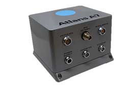
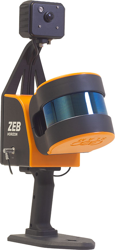
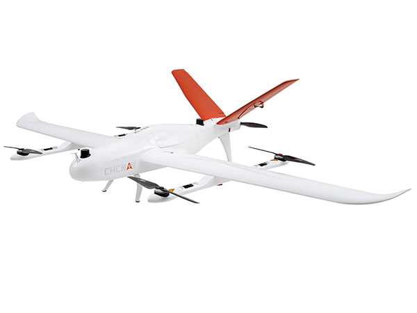
Lidar Unit
Can be mounted on plane or UAV
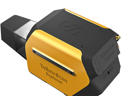
The YellowScan Explorer lidar can be mounted on a light manned aircraft or helicopter, as well as a UAV platform such as the DJI M300. This versatility allows the end user to tackle a wide range of projects with the same unit. It uses an Applanix APX-20UAV GNSS/inertial solution and has a precision of 2.6 cm and an accuracy of 2.2 cm. Its high-power laser scanner can catch points up to 600 meters away. Flight operation speed is 5–35 m/s; it is capable of above-ground-level altitude up to 300 m. The low-weight unit (2.3 kg without battery) can be combined with YellowScan’s suite of software to extract and process point cloud data for surveying, forestry, environmental research, archaeology, industrial inspection, civil engineering and mining sectors.
Yellowscan, yellowscan-lidar.com
UAV
Folding camera drone
Designed for aerial photography

The DJI Mavic 3 improves on its predecessor with better sensors, a dual-camera system, omnidirectional obstacle sensing, smarter flight modes and longer flight times. A powerful positioning algorithm improves hovering precision with signals from GPS, GLONASS and BeiDou satellites, enabling the drone to lock onto multiple satellite signals faster. The increased positioning precision also makes the drone less likely to drift in the air and more stable when shooting long exposures and time lapses. The Advanced Pilot Assistance System (APAS) 5.0 combines inputs from six fish-eye vision sensors and two wide-angle sensors to sense obstacles in all directions and plan safe flight routes.
DJI, dji.com
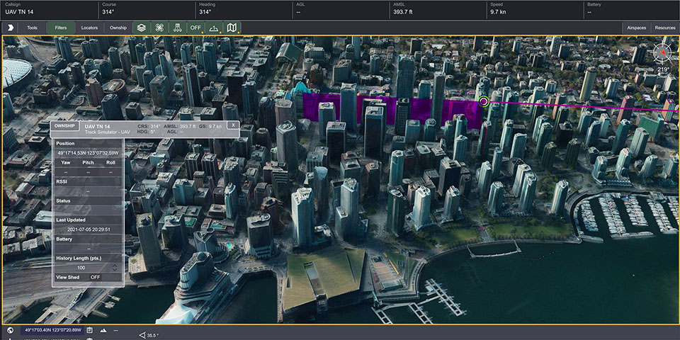
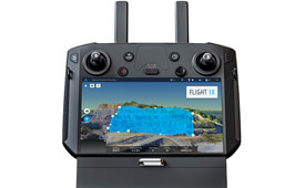
Remote Operations
Conduct missions, manage fleets and view video feeds

SkyGrid’s autonomous remote UAV operations solution enables drone operators to remotely conduct missions, control flights, manage fleets and view live video feeds. Using artificial intelligence and airspace-related data feeds, SkyGrid enables safe remote operations, whether conducting routine inspections or generating optimal flight paths. Advanced route generation capabilities create the safest route for each drone based on the flight plan, environmental conditions, the vehicle’s performance, and the mission criteria with minimum on-site support required. SkyGrid Launch allows video feeds from drones to be consolidated to a remote central location, such as a ground station.
SkyGrid, skygrid.com
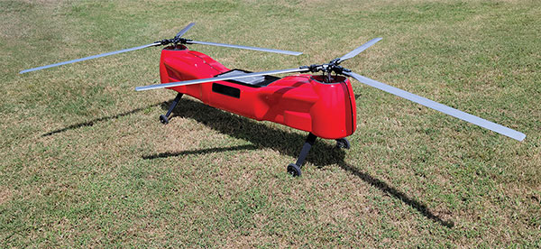
Helicopter
Ready for the long haul
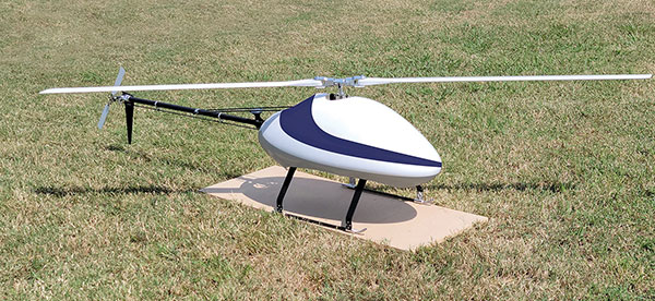
The Sicura EG-1100 is a heavy-lift, long endurance, single-rotor helicopter. Now in its third generation, the helicopter can haul 15 pounds. It cruises at 55 knots. The EG-1100 is available in both electric and gas engine configurations, with an endurance at 3.5 hours on gasoline and 1 hour on electric power. The new gas engine is the high-performing and efficient Skypower 110, tuned to the craft’s internally developed chassis and rotor blades. It offers stable performance in challenging environmental conditions, exceptionally stable flight and immediate flight response for image capture and lidar operations. Multiple payload sets can be carried in one flight.
UAS Global Services, uas-gs.com
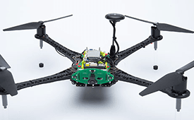
Small UAS
High performance in low weight class
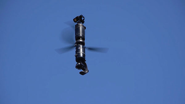
The Spirit dual-rotor coaxial unmanned aerial system (UAS) is a versatile and durable system for mission-critical operations. Combined with a fully modular, plug-and-play payload design, the Spirit’s open architecture allows operators to easily add or upgrade software to unlock new operating capabilities without the need to design or develop a new aircraft. It has an all-weather airframe. With nearly 10 pounds available for batteries and payloads, Spirit sets the new standard for performance in its weight class. Setup is quick and easy, allowing for takeoff from any type of terrain. The highly streamlined all-weather airframe has a top speed of 60 miles per hour and can operate in high winds. Payloads and batteries can be mounted or stacked on the top or bottom point.
Ascent AeroSystems, ascentaerosystems.com