SPH Engineering has released a lidar toolset update to UgCS — the company’s UAV mission planning and flight control software. The lidar toolset is designed to eliminate human error in remote sensing.
Features include precise calibration, flight patterns for route planning, anti-shake turns, and constant line spacing and buffer.
The UgCS lidar toolset allows users to optimize time and cost-effectiveness at all stages of data collection and processing. At the flight planning stage, time is saved on mission planning, with flight patterns and turns designed specifically for lidar surveys.
At the flight stage, users can acquire high-quality laser data with preset inertial measurement unit (IMU) initialization patterns and anti-shake lidar turns. During post-flight data analysis, the high accuracy of the acquired data ensures the desired results with a single trip to the field
“We have received various requests from lidar producers and end-users to improve the accuracy of laser data collected with a UAV,” said lexei Yankelevich, head of software development at SPH Engineering. “We have invested in UgCS R&D to focus mainly on automated IMU calibration commands, automatic calculation of required line spacing and overlap, and prevention of sensor shaking. Trial flights over SPH Engineering’s in-house test range have confirmed UgCS lidar toolset capacity to support main lidar market players.”
Application areas include power line inspections, road inspections, construction, mining, archaeology and forestry.
A new European project is researching automated collection of geodata and production of high-definition maps.
The GAMMS project is funded by the European Union Agency for the Space Programme (EUSPA), and will take place until the end of 2023. Galileo will be the main enabler of GAMMS, given its precise, multipath-resistant measurements and its upcoming high-accuracy service (HAS).
A European consortium, led by the French map service provider GEOSAT, will investigate how the combination of self-driving mapping cars (autonomous mobile-mapping systems) and artificial intelligence-based mapping software can automate the production of high-definition maps.
These maps are used by driverless vehicles and need to be provably accurate, complete and up to date. Fast, sustainable production of trustworthy maps is the goal.
Consortium members include:
GEOSAT — map-making and machine learning
GeoNumerics — multi-sensor fusion and accurate navigation
“It is as challenging as interesting to bring together the geodetic estimation methods with the navigation ones in multi-sensor systems powered by EGNSS and its differentiators, VDMs (vehicle data management systems) and visual features,” said Marta Blázquez, responsible for GAMMS at GeoNumerics. “GAMMS will boost the development of NEXA, our trajectory determination platform, and GENA, our adjustment platform for dynamic networks, in the direction of trustworthy navigation.”
GeoNumerics is responsible for computing the mapping vehicle trajectory (a time series of position, velocity and attitude coordinates) by integrating the manifold of sensors available in a mapping vehicle.
Measurements of inertial units and atomic clocks will be fused with measurements of all available navigation satellites (GPS, GLONASS, Galileo and BeiDou), odometers, cameras and laser scanners. For this purpose, GeoNumerics’ GENA and NEXA systems will be further developed to include new sensor mathematical models and to improve its robust estimation methods.
In June 2019, Regulus Cyber’s experts successfully spoofed the GPS-based navigation system of a Tesla Model 3 vehicle. This experiment provided an important warning for all companies using GNSS location and timing: these technologies, on which they depend, are highly vulnerable to spoofing attacks. In the two years since the experiment, companies and governments have continued to research the potential harm that can be caused by spoofing attacks and are learning more about how to defend themselves from them.
The Tesla experiment was groundbreaking because it was the first time that a level 2.5 autonomous vehicle was exposed to a sophisticated GPS spoofing attack and its behavior recorded.
We chose Tesla’s Model 3 because it had the most sophisticated advanced driver assistance system (ADAS) at the time, called Navigate on Autopilot (abbreviated NOA or Autopilot), which uses GPS to make several driving decisions. However, this experiment exposed several cybersecurity issues potentially affecting all vehicles relying on GPS as part of their sensor fusion for autonomous decision making.
NOA makes lane changes and takes interchange exits once a destination is determined, without requiring any confirmation by the driver. Its several other features include autonomous deceleration and acceleration according to the speed limit, autonomous lane changing, and adaptive cruise control.
These features use a variety of sensors, including cameras, radar, speedometers and more. The researchers wanted to test the extent to which the Model 3 relied on its GNSS receiver to make these driving decisions and how it behaved when receiving contradicting information from its GNSS receiver and its other sensors.
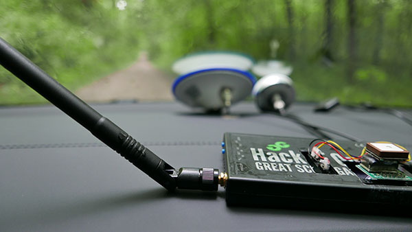
The researchers used hardware and software purchased online to mimic the tools potential hackers would use. The experiment involved two software-defined radio (SDR) devices purchased online, one to spoof GPS and one to jam all other constellations, connected to an external antenna to simulate an external attack. The software used to simulate the GPS signal was downloaded from an online source, available for free.
The test included three scenarios the researchers assumed would involve usage of GNSS, each one using a different spoofing pattern:
Scenario 1. Exiting the highway at the wrong location
Scenario 2. Enforcing an incorrect speed limit
Scenario 3. Turning into incoming traffic
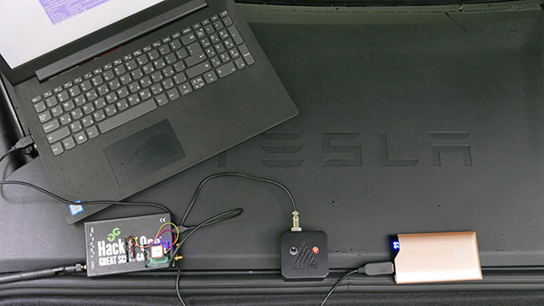
A Tesla Model 3 was remotely hacked in a test of a GPS spoofing attack. (Photo: Regulus Cyber)
Scenario 1: Exiting the Highway at the Wrong Location
The car was driving normally at a constant speed of 95 KPH with NOA enabled. The destination determined for this ride was a town nearby and the car designated a certain interchange as the destination for an autonomous exit maneuver. The experiment began 2.5 km before the vehicle reached that interchange; however, the researchers’ fake GPS signal resulted in coordinates of a location on the same highway but only 150 m before the exit.
As soon as its GNSS receiver was spoofed, the car assumed that it had reached the correct exit and began to maneuver to the right, activating the blinker, slowing down, turning the wheel, and crossing a dotted white line to its right side, exiting to an emergency pit-stop, confusing it with the exit 2.5 km ahead.
To be clear, this would not have happened at any location along the highway, because sensor fusion with the radar and the camera enables the car to avoid physical obstacles and ensures that it does not cross a solid white line that makes a turn illegal.
The spoofing attack succeeded, in that it enabled the attacker to remotely manipulate the car’s sensor fusion and make it exit the highway at the wrong location.
Scenario 2: Enforcing an Incorrect Speed Limit
The car was driving to a random city far away on a highway, at a constant speed of 90 KPH, which was 10 KPH below the highway’s speed limit, with NOA enabled. The researchers generated a fake GPS signal, with the coordinates of a nearby town road that has a speed limit of 33 KPH. Shortly thereafter, the vehicle assumed the speed limit had just changed to 33 KPH and instantly began decelerating. Each time the driver attempted to accelerate using the gas pedal, as soon as he lifted his foot off the pedal the car engaged in heavy braking to quickly decelerate back to 33 KPH.
To be clear, this would not have happened if NOA had been turned off. The cruise mode can be disabled by either using the touch screen or by pressing the brakes, which would allow the driver to regain full manual control over the vehicle’s speed.
Again, the spoofing attack succeeded, in that it allowed the attacker to remotely manipulate the car’s speed and made it enforce a speed limit much lower than the actual one on the highway.
Scenario 3: Turning into Incoming Traffic
The car was being driven manually on a two-lane road with one lane in each direction, the type of road on which NOA cannot be used. The researchers generated a fake GPS signal, with coordinates of a nearby three-lane highway, with all lanes in the same direction. Furthermore, the spoofed location was 150 m from a designated exit that the vehicle’s navigation system was programmed to take, requiring a left turn.
Shortly after the car’s GNSS receiver was spoofed, the vehicle assumed it was on a highway and engaged NOA. Next, it triggered the exit maneuver, which began with activating the left blinker, followed by turning the wheel to the left. The driver had to quickly grab the wheel and manually drive the car back to its lane to avoid a collision with oncoming traffic.
To be clear, this kind of scenario would not be possible without the driver enabling the NOA. Once a Tesla driver enables NOA, it automatically turns on once the vehicle is on the highway with a set destination. This is why the researchers assumed that NOA would be turned on by default, and as long as NOA is activated, the vehicle is susceptible to the attacks mentioned in the experiment.
Once again, the spoofing attack was successful in that it enabled the attacker to remotely steer the vehicle into the opposing lane, placing it on a direct collision course with oncoming traffic. Out of the three scenarios described, this one proved that GNSS spoofing can endanger lives.
The hardware used for the GPS spoofing test. (Photo: Regulus Cyber)
GPS Cybersecurity for Automotive Applications
The NOA system in the Tesla Model 3, being an ADAS, allows drivers to rely on the car and its sensors for basic driving functions. Therefore, it enables drivers to briefly take their hands off the wheel and reduces the number of actions they are required to take. Nevertheless, drivers are still required to be fully attentive to the road so that they can take control of the vehicle at any time.
However, since this spoofing attack had such a sudden and instant impact on the car’s driving behavior, a driver who is not fully attentive and aware would not be prepared to quickly take control and prevent an accident. By the time the driver notices that something is wrong and reacts, it might be too late to prevent an accident. Already drivers have been found sleeping at the wheel, driving under the influence of alcohol, and doing other inappropriate tasks with NOA engaged.
Furthermore, this situation assumes a level 2.5 autonomous vehicle as was tested. But what happens in level 3 vehicles, in which driver engagement is limited, or level 4 and 5, in which driver response is non-existent? This research provides us with a glimpse into the crucial importance of sensor cybersecurity and particularly of GNSS cybersecurity.
The Tesla hack experiment and its results were eye-opening for the autonomous vehicles sector – the danger is real and rising as more and more vehicles are depending on GNSS technology as part of their sensors for assisted or automated driving. Up to 97% of new vehicles since 2019 incorporate GNSS receivers and most if not all are still vulnerable to the same spoofing attacks presented in this research.
In January 2021, the UN’s World Forum for Harmonization of Vehicle Regulations (WP.29) issued Regulation No. 155, which sets guidelines for cybersecurity in the automotive industry with the goal of addressing every possible cyber threat that it might encounter. Annex 5 of the regulation defines cyber attacks and states that in order to get approvals in the future vehicle manufacturers will need to provide solid evidence that their vehicles are sufficiently protected against them.
Among the cyber threats mentioned in the Annex is spoofing of data received by the vehicle — both sybil spoofing attacks and spoofing of messages. The Annex also lists the appropriate protection that vehicle manufacturers should implement and states that vehicle manufacturers will be required to provide evidence of the effectiveness of the mitigation measures they choose. These upcoming regulatory requirements can make the difference between life and death in situations caused by GNSS spoofing and ensure that only reliable and resilient positioning is used within vehicles, both today and in the future.
Please note: Tesla released a statement saying that it is “taking steps to introduce safeguards in the future which we believe will make our products more secure against these kinds of attacks.” Regulus Cyber researchers did not perform any further experiments with Tesla Model 3 since this research was published two years ago.
See the Tesla GPS spoofing experiment from the driver’s point of view:
Are ‘”flying cars” unmanned aerial vehicles, manned aircraft, electric aircraft or just regular aircraft? Or perhaps a mix of all of these? Flying cars raise so much interest because of their potential to fulfill the space-age Jetsons promise, with the regular family parking one at their house, then using it to go to work, go grocery shopping and take the kids to school — all the things we do today in cars on roads.
The U.S. Air Force recognized that flying cars could also revolutionize how it operates, and in 2020 started putting effort and cash into promising commercial flying-car ventures. Since then, the Air Force has begun to make progress. Its AFWERX Agility Prime program has helped four companies — Kitty Hawk Aero, Beta Technologies, Joby Aviation and Lift Aircraft — develop prototype commercial flying-cars and expand their capabilities.
The Kitty Hawk Aero Heaviside
Kitty Hawk Aero in Palo Alto, California, has been working on its electric vertical take-off and landing (eVtol) aircraft for several years and claims to have proven its tilting propeller concept through several hundred vertical take-off/landing to horizontal flight transitions.
The aircraft — known as Heaviside — has just been granted airworthiness approval by the Agility Prime program, enabling Kitty Hawk to further participate in specialized trials funded by the Air Force.
Heaviside takes off vertically. (Photo: Kitty Hawk)Heaviside comes in for a landing. (Photo: Kitty Hawk)
The majority of flight testing flown by Heaviside has been remote without on-board crew (one or two pilots). This has enabled Kitty Hawk to expand the flight envelope without risking lives. For instance, you might assume those initial vertical to horizontal transitions could have carried a degree of risk, even though those switches in flight mode are now considered virtually risk free.
Nevertheless, the aircraft is also equipped with an on-board parachute recovery system that has been demonstrated to gently lower the aircraft to the ground in the event of a complete electrical failure. The design has minimized weight, even though the aircraft carries sufficient battery power to provide a range of more than 100 miles. A speed of up to 180 mph has been achieved.
The Beta Technologies Alia
Another AFWERX participant in the Agility Prime project is also well along in its flight test program. Beta Technologies has been flying its Alia prototypes on routes of more than 100 miles and pushing velocities of 150 mph.
Alia eVtol aircraft. (Photo: Brian Jenkins/Beta Technologies)
Alia is large — it’s in the 7,000-pound aircraft category with a 50-foot wingspan. Alia is designed to carry six people over 250-mile routes, with a cargo capacity of 1,500 pounds. It is powered by on-board lithium-ion batteries. The Air Force expressed serious interest in the design and flight-test planning phase before Alia became airborne. The craft has since proven it is capable of safe, reliable flight over routes such as Plattsburg to New York. The Federal Aviation Administration has authorized such flights ahead of time, but Beta also just received additional airworthiness authorization from the Agility Prime office to enable further trials.
The Air Force clearly has great faith in Beta Technologies. The company received an even greater boost to its Beta eVtol program from the commercial sector. BLADE Urban Air Mobility has already ordered 20 of these electric aircraft, and UPS has also ordered 10, with the expectation that their order could grow to up to 150. UPS can clearly see the time and cost advantage of landing aircraft directly at its package-sorting facilities, then loading and vertically launching Alai onto delivery routes, either manned or autonomously as a cargo UAV. United Therapeutics, which is developing artificial organs for human implantation, is another key sponsor, presumably to find the shortest transit time to client hospitals.
Amazon also may become involved following Beta’s recent successful $368 million funding round led by Fidelity and Amazon’s Climate Fund, giving the company stratospheric “unicorn” valuation of more than $1 billion. Maybe there could be Amazon package delivery service in Beta’s future.
The Joby Aviation Craft
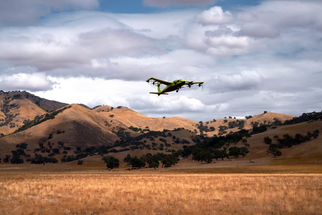
Joby Aviation is another earlier participant in the U.S. Air Force’s Agility Prime program and was granted airworthiness authorization in 2020. Joby first flew a subscale prototype in 2015 and a full-size aircraft in 2017, with the objective of proving the viability of a tilt-rotor, four-passenger flying taxi/eVTOL aircraft.
Joby eVTOL in flight in Northern California. (Photo: Joby Aviation)
Joby’s story may be similar to the other companies developing electric flying cars, save that it has been doing this since 2009. Over time, Joby has won significant funding and support from key industry sponsors including Toyota, Uber, Elevate and Agility Prime. A study by Lufthansa in 2021 touted Joby as the leader in the eVtol competition.
The FAA has agreed that Joby can proceed down a certification path applying regular general aviation part 23-64 rules, plus special conditions that include special attention for batteries and fly-by-wire controls. Joby is making good progress toward certification objectives, having already flown more than 1,000 times with different prototypes.
With six tilt-rotors driven by electric motors, Joby’s yet-to-be-named four-passenger aircraft is capable of 200 mph with a +150-mile range, weighs 4,000 pounds and is apparently one of the quietest, measuring only 65 dBA at ~110 yards while hovering. A low noise profile is key to acceptance of these relatively low-altitude flying-cars as they buzz across densely populated areas — and all manufacturers have come up with low-noise-profile designs.
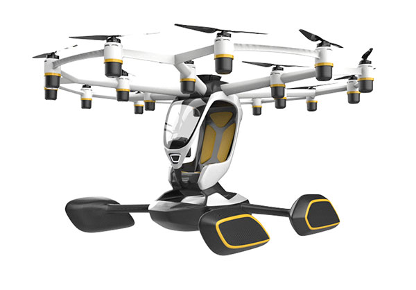
The Lift Aircraft Hexa
Lift Aircraft has taken a different path toward introducing flying-car technology into everyday use by borrowing more closely from existing drone capabilities. The company hopes acceptance will be quicker under its adopted FAA’s Powered Ultralight classification (FAR Part 103), which does not require a pilot’s license to fly.
The Lift approach also intends to take so many precautions and use so much automation that anyone can fly its Hexa. Floats prevent sinking for forced landings on water; triplex flight-computers, GPS and IMUs add to the fail-safe design; and an automatic parachute release in the event of an in-flight incident deploys a “whole-aircraft air bag.” Along with 18 redundant electric-motor-driven propellers (only 12 are needed for a safe landing), these features add up to safety for the uninitiated.
Hexa single-pilot drone-car. (Photo: Lift)
The single joystick control is simple to use and allows the unskilled to fly the drone-car safely. The system comes with extensive monitoring built in, so remote safety operators can intervene in extreme situations. Flight is currently only allowed in geo-referenced airspace defined by Lift. The vehicle has the capability to fly itself out of potentially dangerous situations and avoid mapped obstacle locations. Flight is semi-autonomous and take-off and landings are automated.
Agility Prime joined with Lift in April 2020 to support the company’s safety testing, and in August 2020, funded expansion of the Hexa flight envelope. The Air Force has loaded a Hexa drone-car into a C-130 transport aircraft and flown it to another location to verify transportability for remote deployments. Lift has also won another contract from the Air Force for autonomous cargo retrieval based on a subset of the Hexa design elements.
It is possible that many people will see Hexa in operation during a coming demonstration tour planned for major population centers across America – 15,000 people have apparently already signed up to fly Hexa when the tour gets underway, possibly later this year.
Wrapping It Up
So are these craft flying cars, or drones carrying people? It’s still hard to say definitively, but for sure many experts believe in the forecast of 160,000 flying taxi-cars by 2050, with airport shuttle and air-taxi markets reaching a market value of $500 billion. Certainly the Agility Prime program seems to have got it right and taken the necessary steps to ensure this technology gets out of its emerging, curio stage and out into a world eager to adopt it. If only we could accelerate the extremely lengthy civilian certification phase while still embedding increasing levels of safety. Perhaps the Air Force program can get us there quicker.
A roundup of recent products in the GNSS and inertial positioning industry from the July 2021 issue of GPS World magazine.
OEM
GNSS/INS Sensors
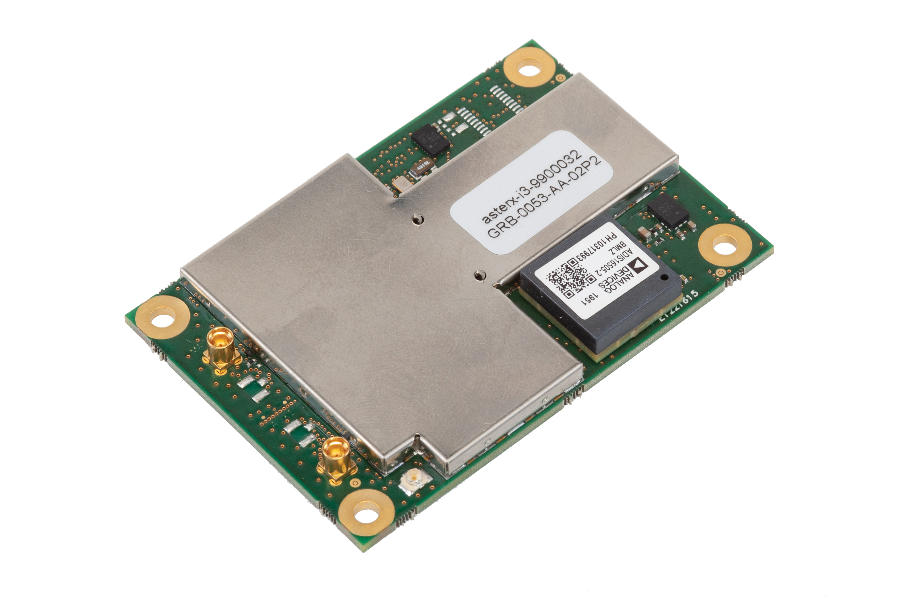
Photo: Septentrio
Five receivers in new product line
The AsteRx-i3 product family provides an array of next-generation receivers, from plug-and-play navigation solutions to feature-rich receivers with raw measurement access. Included are OEM boards and ruggedized receivers enclosed in a waterproof IP68 housing. The Pro receivers offer high accuracy positioning with 3D orientation and dead-reckoning for plug-and-play integrations. Pro+ receivers provide integrated positioning and orientation along with raw measurements, in single- or dual-antenna configurations, suitable for applications with sensor fusion. One of the receivers offers an off-board inertial measurement unit (IMU), which can be mounted exactly at the alignment point of interest.
The RES 720 GNSS dual-frequency embedded timing module provides next-generation networks with 5-nanosecond accuracy. It uses L1 and L5 GNSS signals to provide superior protection to jamming and spoofing, mitigates multipath in harsh environments, and adds security features to make it suitable for resilient networks. At 19 x 19 millimeters, the RES 720 is suitable for 5G Open Radio Access Networks (RAN)/XHaul, smart grids, data centers, industrial automation and satellite communication networks, as well as calibration services and perimeter monitoring applications.
The new HG1125 and HG1126 IMUs are low-cost inertial measurement units that serve both commercial and military applications. They use sensors based on micro-electromechanical systems (MEMS) technology to precisely measure motion. They can survive shocks up to 40,000 G-force. The HG1125 and HG1126 can be used for a variety of defense and commercial applications, such as tactical military needs, drilling, unmanned aerial vehicles or navigation systems for general aviation aircraft.
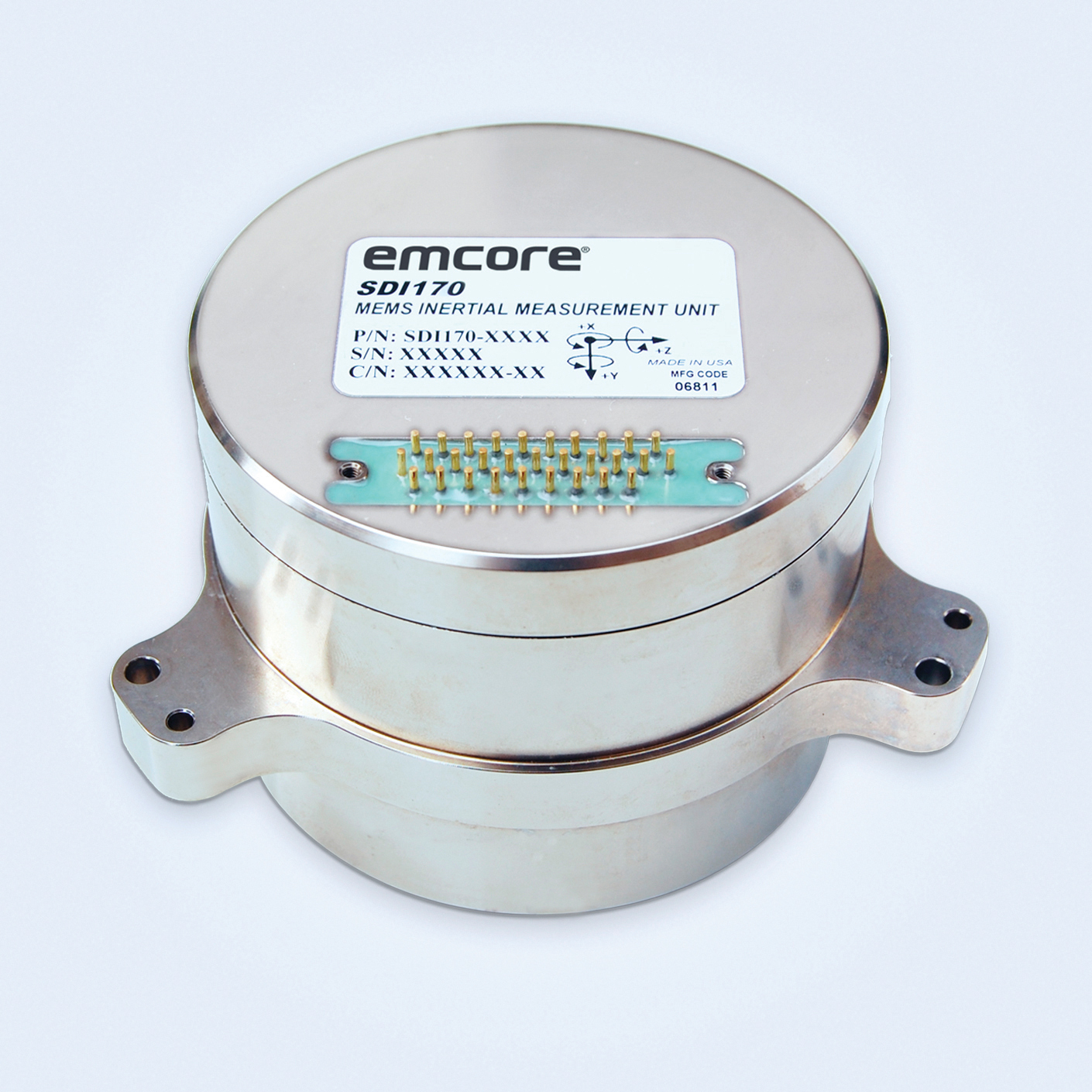
The SDI170 quartz MEMS tactical-grade IMU is designed as a form-, fit- and function-compatible replacement for the HG1700-AG58 ring-laser gyroscope (RLG) IMU, but with superior overall performance, versatility and a significantly higher mean time between failures (MTBF) rating over ruggedized environments. The SDI170 IMU delivers highly linear accelerometer performance and longer life compared to the HG1700 IMU.
The OSA 5405-MB is a compact outdoor precision time protocol (PTP) grandmaster clock with a multi-band GNSS receiver and an integrated antenna. It ensures timing accuracy by eliminating the impact of ionospheric delay variation, enabling communication service providers and enterprises to deliver the nanosecond precision needed for 5G fronthaul and other time-sensitive applications. A multi-constellation GNSS receiver and antenna enable the OSA 5405-MB to meet PRTC-B accuracy requirements (+/–40 nanoseconds) even in challenging conditions. It receives GNSS signals in two frequency bands, using the differences between them to calculate and compensate for ionospheric delay variation. The OSA 5405-MB is resilient against jamming and spoofing, considered critical for 5G synchronization. It can work with up to four GNSS constellations concurrently (GPS, Galileo, GLONASS and BeiDou).
The Toughbook S1 is a fully rugged 7-inch Android tablet for capturing and accessing critical information in the field. GPS and LTE come optionally. The tablet is supported by Productivity+, a comprehensive Android ecosystem that enables customers to develop, deploy and sustain the Android OS environment in the enterprise. The Toughbook S1 tablet’s compact, rugged and lightweight body is made for portability and reliability for field workers. It has a 14-hour battery life and warm swap battery. Features include a sleek outdoor-readable anti-reflection screen, patented rain mode and multi-touch performance whether using a stylus, finger or glove.
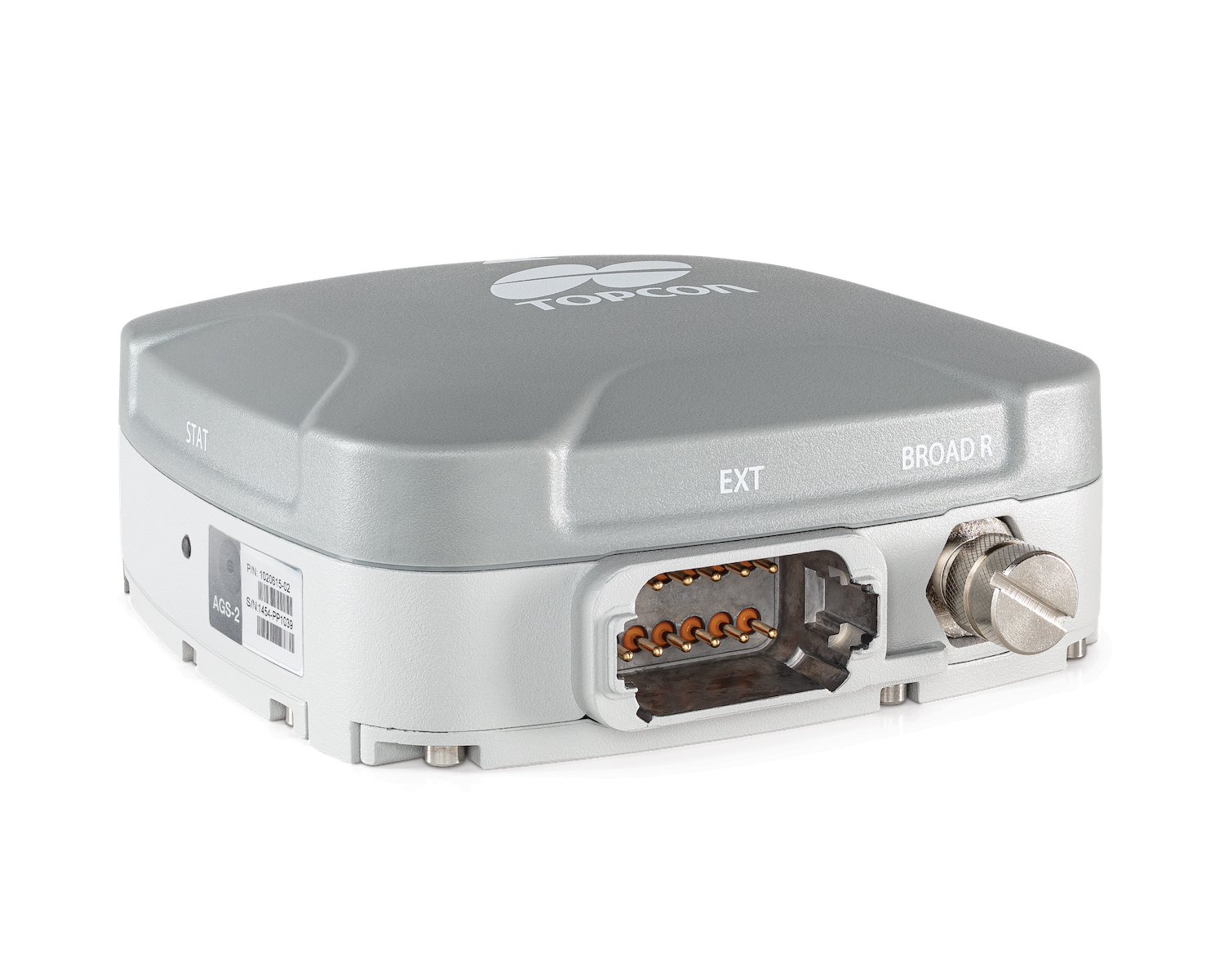
The AGS-2 and AGM-1 are manual guidance and autosteering receivers. Location data enable crop optimization, including soil preparation, seeding, crop care and harvesting. Designed to suit virtually any agricultural machine type, make and model, the AGS-2 receiver and steering controller combines steering with network reception and tracking. It comes standard with DGNSS correction services and is upgradeable using NTRIP and an optional RTK radio in the Topcon CL-55 cloud connectivity device. The AGM-1 is offered as an economical entry-level manual-guidance receiver.
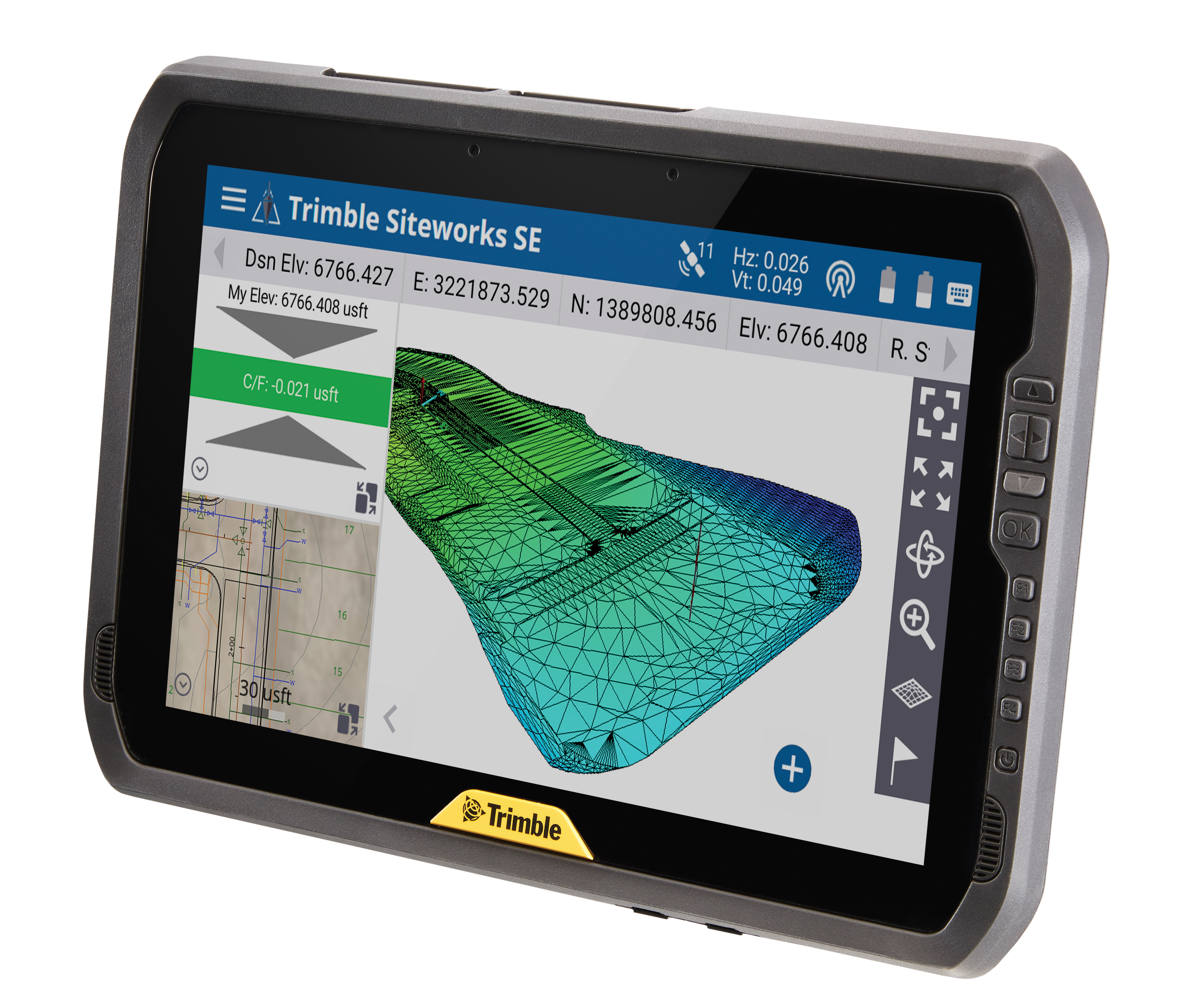
Provides fast data processing for construction and surveying
The Trimble T100 high-performance tablet is suitable for both experienced and novice users. It is optimized for Trimble Siteworks Software and supporting office applications such as Trimble Business Center. Its accessories are designed to complement user workflows, enabling users to complete quality assurance and quality control before leaving the field. The tablet is designed to be flexible and usable in a variety of configurations and job sites. It is engineered to be ergonomic and portable on and off the pole. Features include a 10-inch (25.4 cm) sunlight-readable touchscreen display, a directional keypad with programmable function keys and a 92-Wh internal battery.
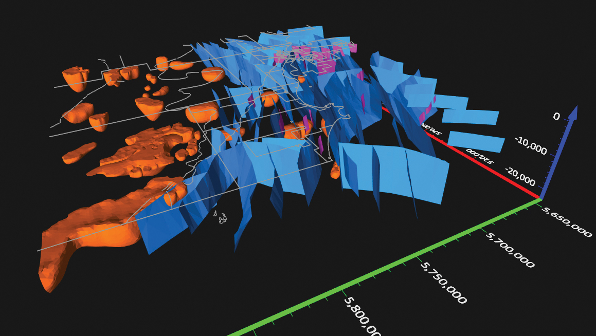
Surfer has new gridding, contouring and surface mapping software to make it easier for users to visualize, display and analyze complex 3D data. Surfer enables users to model data sets, apply an array of advanced analytics tools, and graphically communicate the results. The scientific modeling package is used in oil and gas exploration, environmental consulting, mining, engineering and geospatial projects. Enhancements have been made to 3D Base Maps, Contour Volume/Area Calculation, 3D PDF Exporting Options and automated features for creation of scripts and workflows.
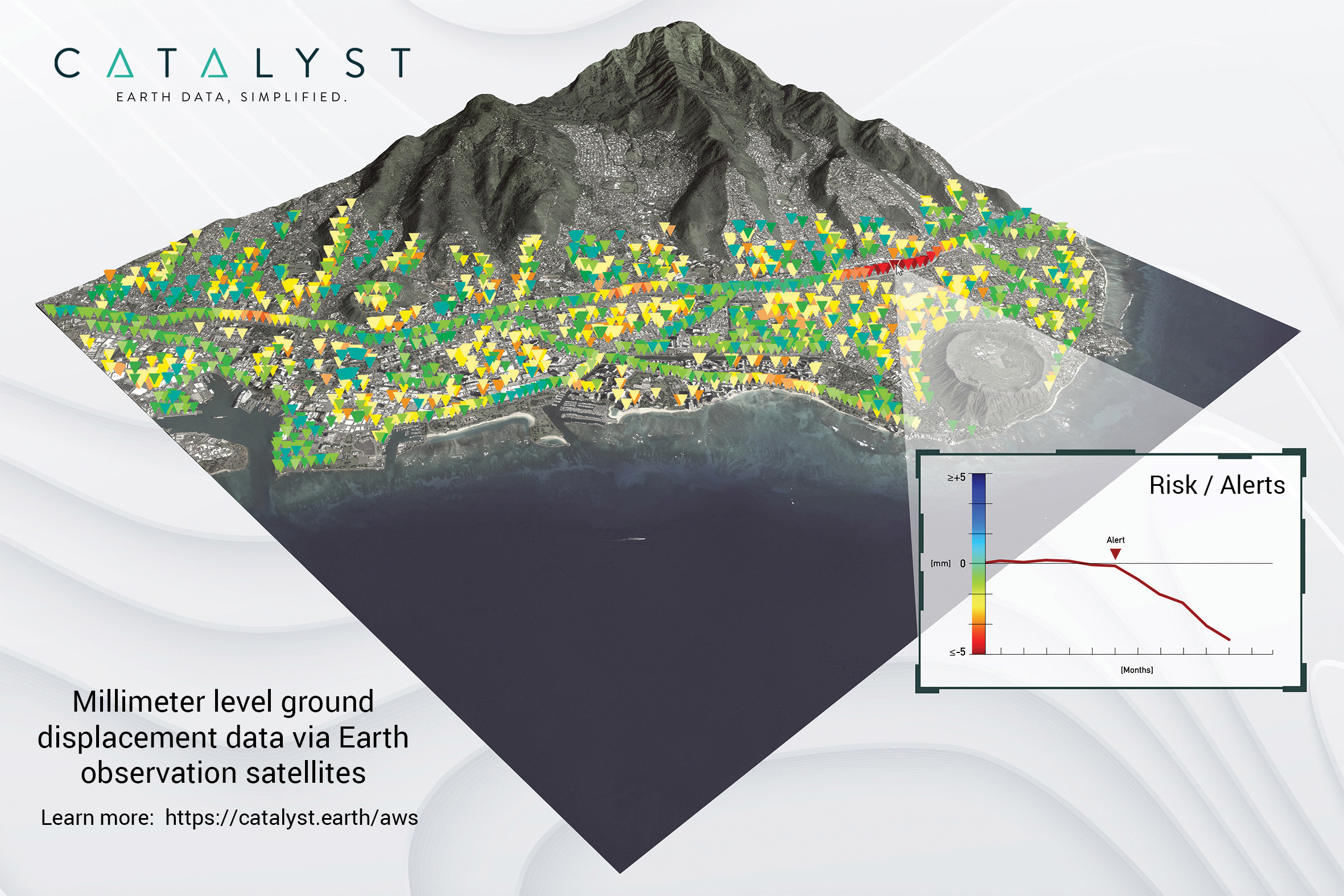
A Catalyst-AWS collaboration delivers actionable geoscience analytics to users, providing satellite-based Earth observation intelligence. The data and analytics are delivered via Amazon Web Services (AWS) Cloud. Catalyst is a PCI Geomatics brand. The initial solution, available through AWS Data Exchange, is an infrastructure risk-assessment service that uses satellite data to continuously monitor millimeter-level ground displacement over a subscriber’s area of interest anywhere on Earth. Catalyst is exploring additional risk mitigation solutions and monitoring services using AWS. Having image processing science and imagery on the cloud reduces latency and costly data transfers.
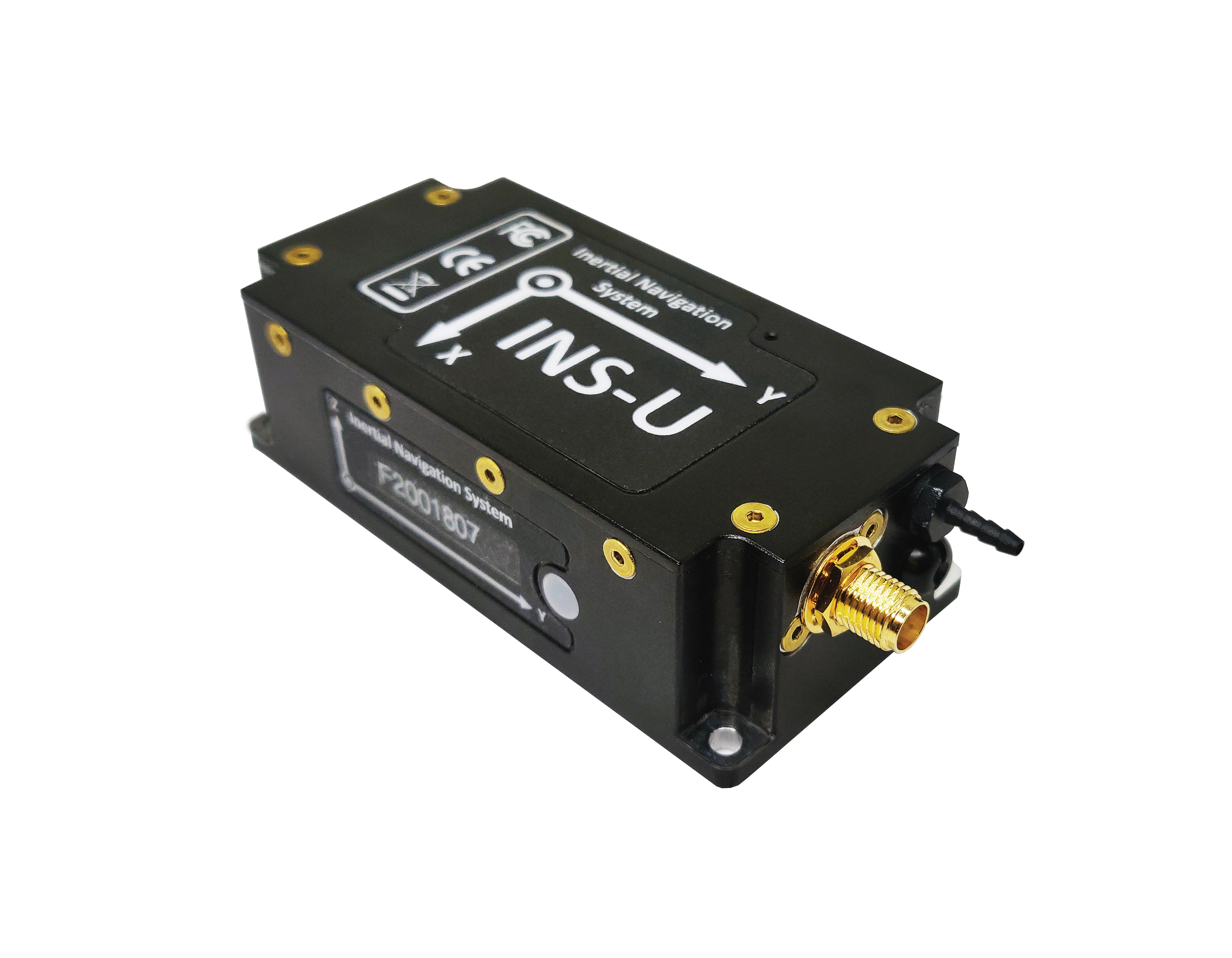
The GPS-aided INS-U is a fully integrated attitude and heading reference system (AHRS), IMU and air-data computer high-performance strapdown system that determines position, navigation and timing information for any device on which it is mounted. The INS-U uses a single antenna, multi-constellation u-blox GNSS receiver. With access to GPS, GLONASS, Galileo, QZSS and BeiDou, the INS-U can be used in a variety of GPS-enabled environments and is protected against spoofing and jamming. The INS-U has two barometers, a miniature gyro-compensated fluxgate compass, and tri-axis temperature-calibrated advanced MEMS accelerometers and gyroscopes. These high-performance sensors, along with Inertial Labs’ new on-board sensor-fusion filter, and state-of-the-art guidance and navigation algorithms, provide accurate position, velocity and orientation of the device under measurement.
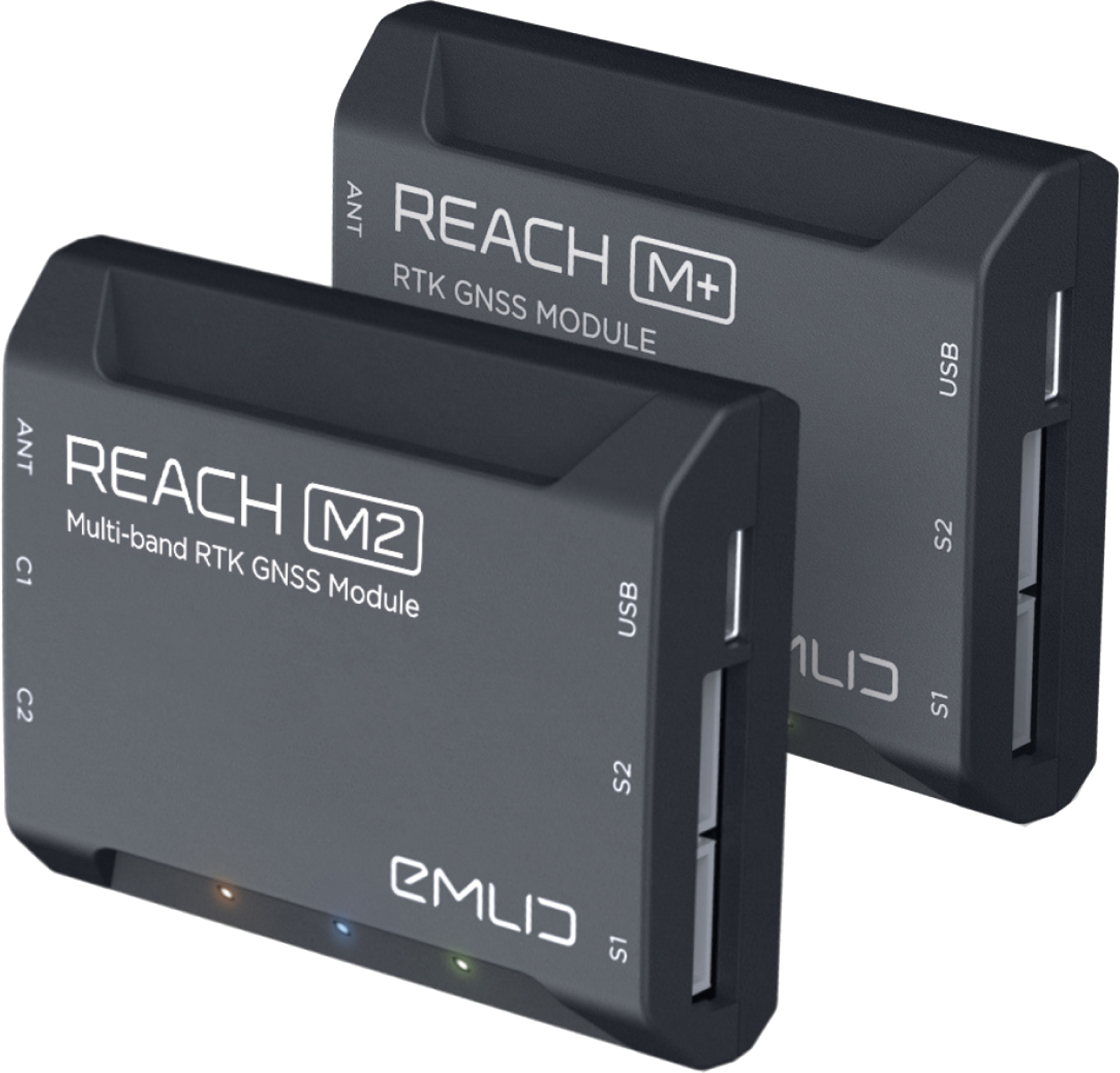
The Reach M+ and Reach M2 positioning modules for UAV mapping provide centimeter-level accuracy in real-time kinematic (RTK) and post-processed kinematic (PPK) modes, enabling precise UAV mapping with fewer ground control points. The Reach M+ single-band receiver has a baseline up to 20 kilometers in PPK. The Reach M2 is a multi-band receiver with a baseline up to 100 kilometers in PPK. Reach connects directly to a camera’s hot-shoe port and is synced with the shutter. Time and coordinates of each photo are logged with a resolution of less than a microsecond. Reach captures flash sync pulses with sub-microsecond resolution and stores them in a raw data RINEX log in the internal memory. This method allows ground control points to be used only to check accuracy.
System simplifies drone inspection missions, deliveries
The Dronehub is an automated solution that can provide undisturbed drone service 24/7 in nearly any weather condition. With the integration of IBM artificial intelligence technology, Dronehub solutions can operate and automatically provide information with little human interaction. The system includes the drone and a docking station with automatic battery replacement. It can fly for 45 minutes in +/–45° C weather, up to 35 km in winds up to 15 m/s. It can carry a payload up to 5 kg as far as 15 km. It can be used for monitoring, inspection and measurement; cargo transport and parcel deliveries; and mobile ground infrastructure; and security.
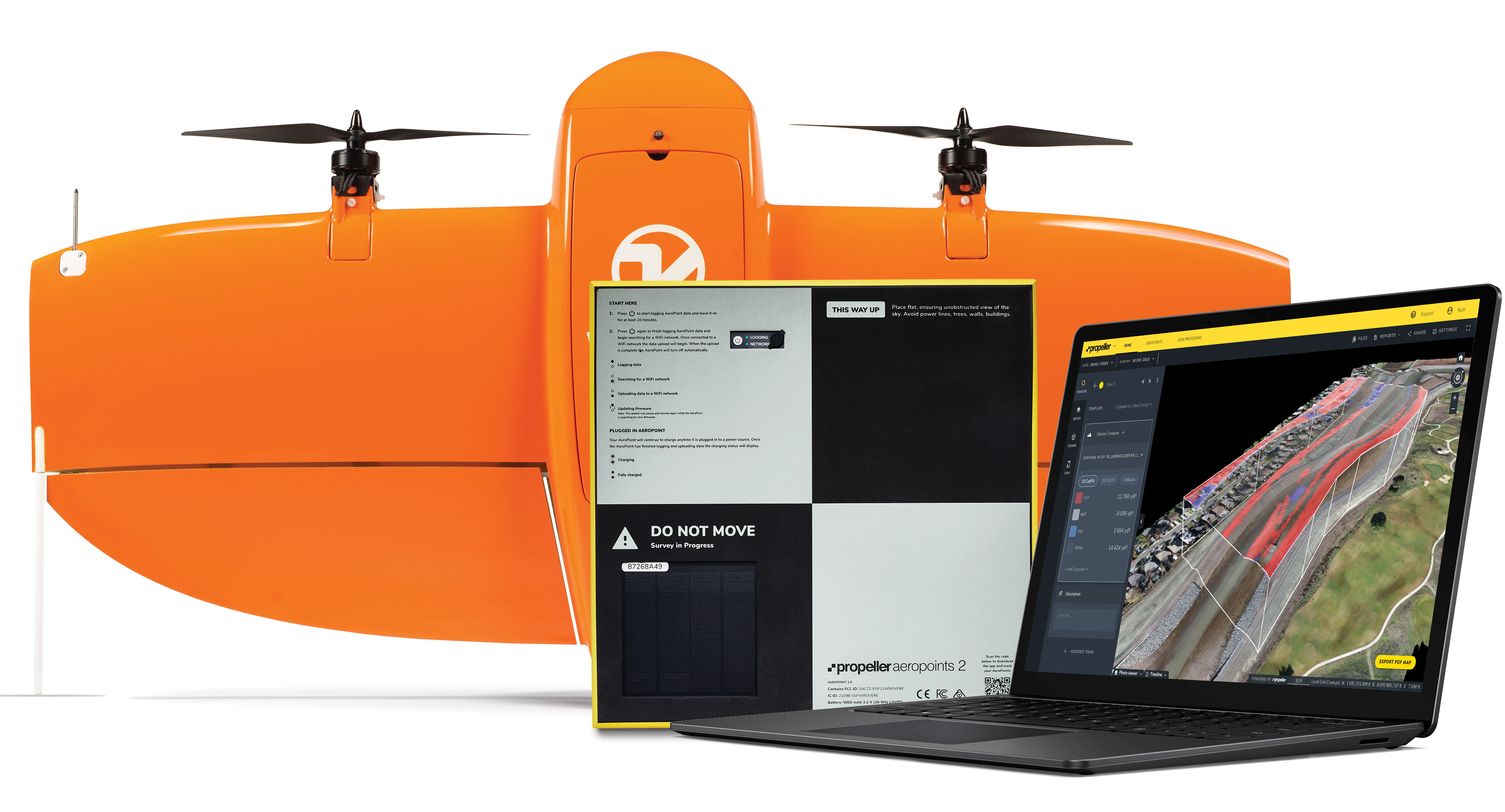
The Propeller Platform and WingtraOne drone package enable construction professionals to collect survey-grade data across the worksite consistently and accurately. To operate, surveyors place Propeller AeroPoints (smart ground-control points) on their worksite, and then fly the WingtraOne drone to collect worksite survey data. Survey images are uploaded to Propeller’s cloud-based platform, where the fully automated geotagging and photogrammetry processing is completed within 24 hours of submission on the platform. Uses include mines, road and railway projects, highways and industrial complexes. Data collection with AeroPoints and Propeller PPK can serve as a reliable, single source for survey data and progress. Teams across the entire worksite can view geographically accurate and realistic 3D site models and track, inspect and report on job progress and productivity safely and accurately.
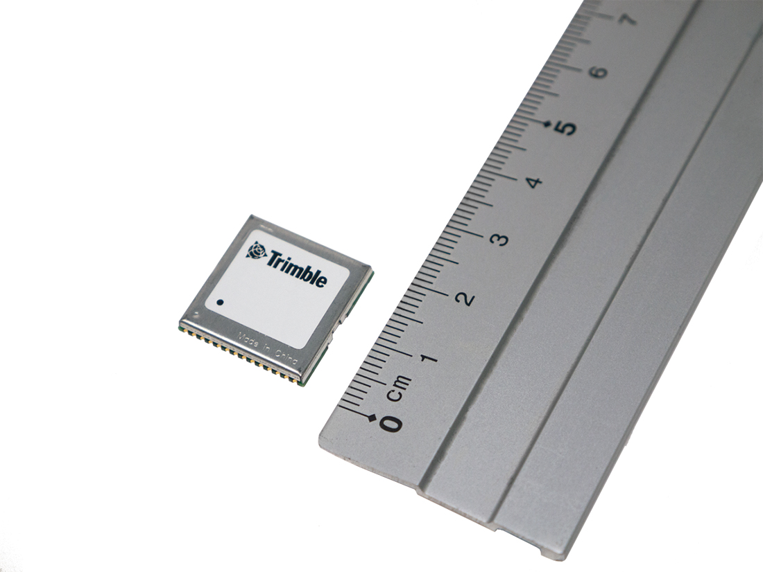
Stamp-sized module provides RTK positioning and heading
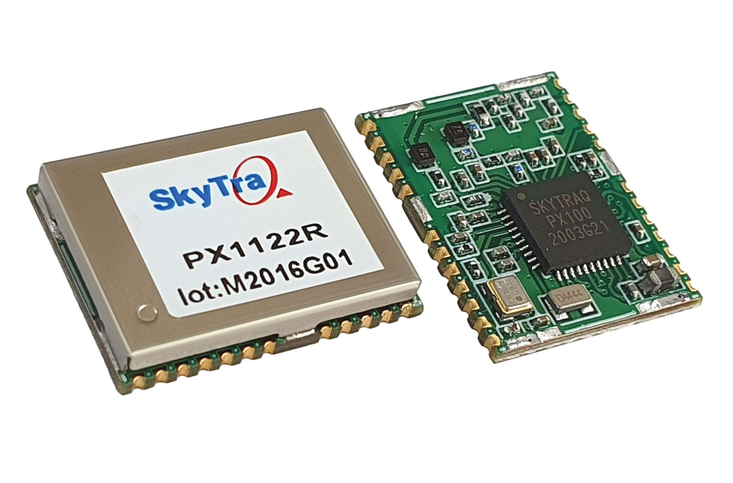
The PX1122R is a high-performance multi-band quad-GNSS real-time kinematic (RTK) receiver featuring 1 cm + 1 ppm position accuracy and under 10-second RTK convergence. It has a 12 x 16 millimeter form factor, about the size of a postage stamp. It can be configured for a base or a rover, and supports a moving base RTK for precision heading applications. The PX1122R has a maximum quad-GNSS RTK update rate of 10 Hz, providing a quick response time and more stable performance for fast-moving precision guidance applications.
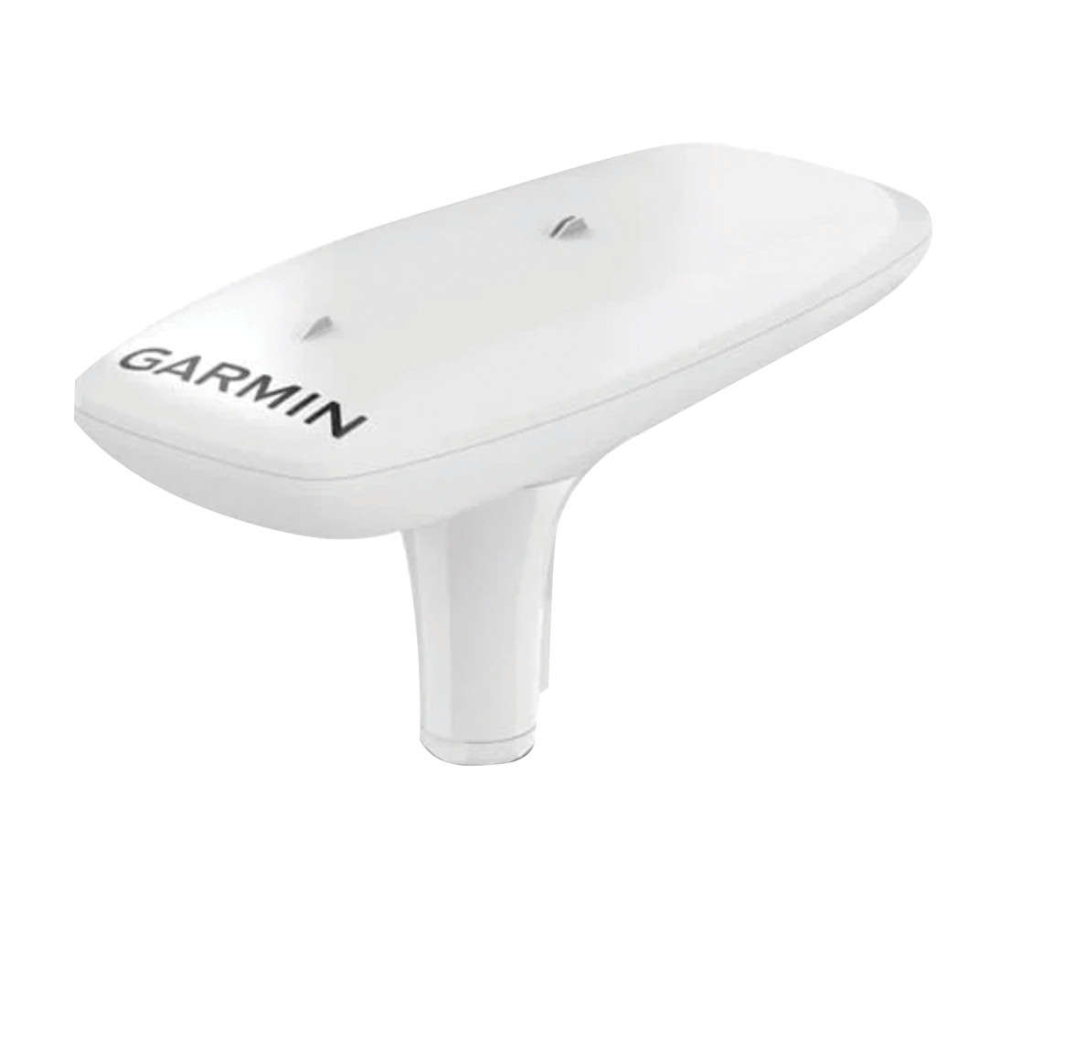
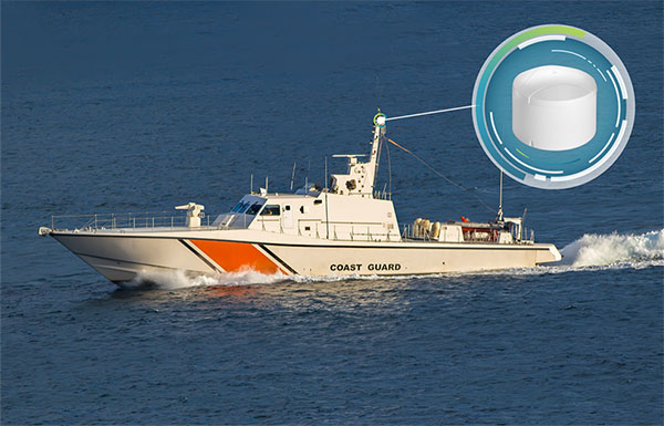
Utilizing both L1 and L5 GPS frequencies, along with multi-constellation support (GPS, Galileo, GLONASS and BeiDou), the MSC 10 marine satellite compass provides precise positioning and heading accuracy within 2 degrees. Its 10-Hz position update rate delivers detailed tracking information. It eliminates magnetic interference, which can degrade heading accuracy. The MSC 10 is easy to install and can be used as the primary position and heading sensor across multiple systems, including autopilots. If the satellite signal is lost, it will transition from GPS-based to a backup magnetometer-based heading.
How will widespread deployment of 5G most benefit GNSS?
Greg Turetsky
“The connectivity options that widespread 5G offer will accelerate multiple GNSS benefits. The high bandwidth is starting to encourage many into the RTK domain, but I think the bigger opportunity may come from the low power versions that enable IoT applications. The combination of the ubiquity of cellular connectivity with the low power of NB-IoT could truly accelerate the real time asset management sector all the way down to the package/pallet level.” — Greg Turetzky
Allison Brown
“Widespread deployment and adoption of 5G is likely to continue to increase the demand for spectrum as broadband access continues to expand. The recent FCC decision allowing Ligado to operate terrestrial networks in bands near GPS is likely not the last decision that will result from this increasing demand. It is not clear to me that 5G deployment will ‘benefit’ GNSS and chipset vendors may need to prioritize developing products that have improved robustness in the presence of nearby interference.” — Alison Brown
Miguel Amor
“The benefit of 5G will be seen in the long term, when 5G ranging capability is available. Hybrid positioning algorithms using both 5G and GNSS observations will provide significant positioning benefits in challenging urban environments and seamless navigation between indoor and outdoor environments. Applications across markets will see the benefits of hybrid 5G and GNSS navigation, but the real advantage lies in how this hybrid will enable the future of autonomous mobility. We will see both technologies working closer together to deliver a seamless and ubiquitous positioning solution.” — Miguel Amor
Mitch Narins
“Like communications, the ability to precisely and securely position and navigate is an essential part of 21st century life. Together they must support both critical and non-critical operations. This requires finding a common understanding of spectrum needs and how to have the best of both. In the long run, end runs by either side may achieve myopic goals but will damage society. The problem is crying out for an enterprise-level systems engineering leadership that can plot our future spectrum course. Else, the push for spectrum will continue, fueled by ‘entrepreneurial spirit’ and often a lack of understanding of the importance of other spectrum uses.” — Mitch Narins
A roundup of recent products in the GNSS and inertial positioning industry from the August 2021 issue of GPS World magazine.
OEM
GNSS board
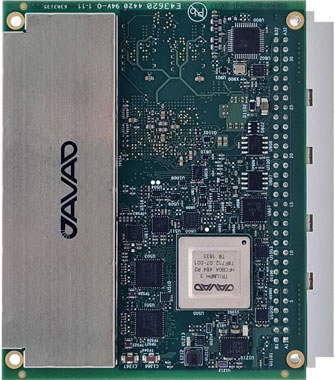
Photo: Javad GNSS
With GLONASS dynamic calibration
The TRE-3S GNSS board measures 100 x 80 mm, weighs 87 g and tracks 874 channels with all-in-view satellite tracking. It includes numerous features to protect against interference and improve signal output: spectrum data output, spoofing detection, advanced multipath reduction, in-band interference rejection, GLONASS 0.2-mm dynamic calibration, heading determination, attitude determination and fast acquisition channels. The TRE-3S receives GPS L1/L2/L2C/L5; Galileo E1/E5A/E5B/AltBoc/E6; GLONASS L1/L2/L3; BeiDou B1/B1C/B2/B3; QZSS L1/L2/L5/L6 (L61/L62); and SBAS L1/L5. It has a 20-Hz update and real-time kinematic (RTK) rate for real-time positioning and raw data (code and carrier). Optional features include tracking QZSS L6 (LEX) and IRNSS L5/S-band, and a data update rate and RTK rate of 100 Hz.
For high-precision applications with L-band corrections
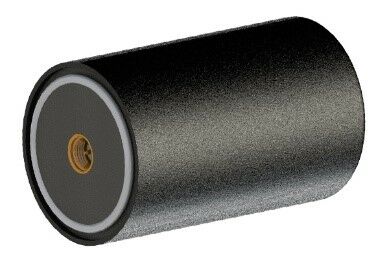
Photo: Maxtena
The M9HCT-A-SMA is a patented helix antenna for GNSS plus L-band corrections services, suitable for high-precision and autonomous multi-frequency applications. It provides simultaneous GNSS reception in a rugged, compact form factor. The M9HCT-A-SMA is suitable for high-precision applications such as the UAV market, where high performance and low weight are driving features in antenna selection. The active helix design features Maxtena’s patented compact and lightweight Helicore technology, which provides excellent pattern control, polarization purity and high efficiency in a compact form factor.
New eXtended Filtering (XF) is now employed in the TW3900 series of Accuntena precision antennas. The XF feature mitigates interference from all near-band signals and ensures the antenna provides the purest possible GNSS signals. The custom XF filtering has been tested to mitigate new (in Europe and Japan) and existing LTE signals, enabling the XF antennas to produce clean and pure GNSS radio frequency data. The XF models are TW3972XF, TW3972EXF, TW3972LGXF, TW3967XF and TW3967LGXF. All are triple-band antennas that support GPS/QZSS (L1/L2/L5), GLONASS (G1/G2/G3), Galileo (E1/E5ab), BeiDou (B1/B2/B2a), NavIC L5 and L-band correction services.
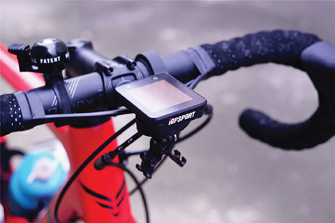
The iGS320 cycling computer builds on the u-blox M10 positioning platform, leveraging the M10’s ultra-low power consumption, compact size, and ability to track all four GNSS to offer endurance athletes a superior user experience. Adopting the M10 in its iGS320 cycling computer brought iGPSPORT an 80 percent increase in the power autonomy to deliver 72 hours of continuous tracking, up from 40 hours in their previous device. Concurrent reception of up to four GNSS constellations increases coverage and accuracy in otherwise challenging signal environments.
The Beamo 3D mapping platform enables surveyors to scan a project site and immediately collaborate with teams in the field without lengthy delays or cumbersome equipment. The digital twin created in the platform provides a single and secure source of truth for teams without requiring highly technical knowledge. With a 360-degree camera, surveyor teams can create detailed digital environments that remote teams can use to track progress, collaborate with coworkers, and take accurate measurements without having to physically visit the site.
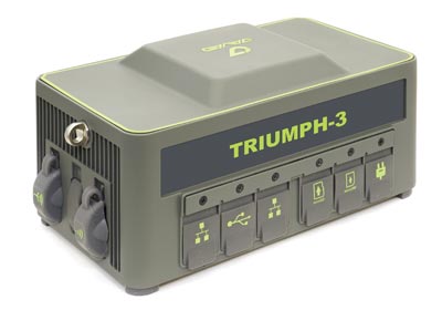
The Triumph-3 receiver tracks efficiently even in difficult conditions. It can track all current signals and is ready for future satellites. The Triumph-3 can operate as a base together with Triumph-LS and Triumph-LS Plus to efficiently accomplish any geodetic job. Its RTK system communicates via integrated UHF, 4G/LTE, Wi-Fi and Bluetooth channels, and eliminates the need to subscribe to a real-time network for corrections. A powerful and reliable receiver for high-precision navigation systems, the Triumph-3 is based on the Javad GNSS 874-channel chip. It is equipped with an internal 4G/LTE/3G card and secure and accessible microSD and microSIM cards. It also supports Javad’s lift-and-tilt technology.
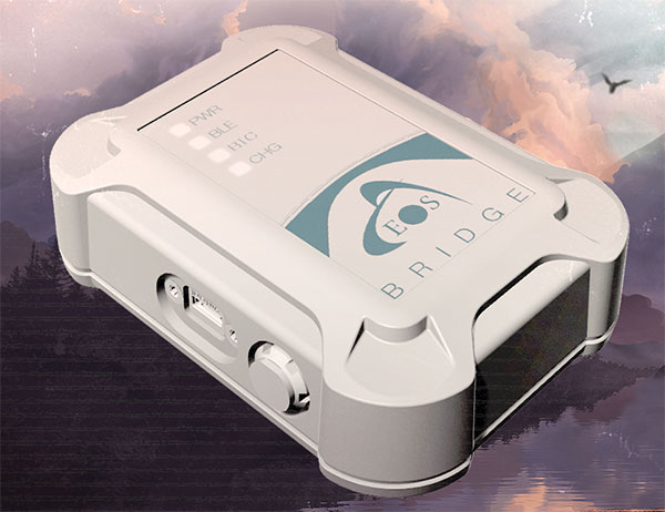
Eos Bridge enables almost any instrument to become iOS Bluetooth compatible. The pocket-sized device connects to instruments via Bluetooth Classic or serial port, and then transmits data to any Apple iOS device, such as iPhone or iPad, Android device or Windows mobile device. Instruments equipped with non-iOS Bluetooth can connect to Apple iOS devices using the Eos Bridge, including laser rangefinders and utility-locating instruments. Instruments whose only connectivity option is a serial port also can connect, such as any instrument or sensor with an RS-232 serial port. The Eos Bridge is lightweight, at approximately 150 grams (about 5.3 ounces). It can be worn clipped to a belt, stored in a pocket, or mounted to an instrument or sensor. The battery lasts 48 to 72 hours.
The OceanReports web tool provides users with specialized “ocean neighborhood analyses,” including maps and graphics, by analyzing more than 100 ocean datasets instantaneously. Reporting data includes information about habitats and species, industries in the area, potential hazards (such as undersea cables or shipwrecks), the economic value of ocean commerce, and other detailed oceanographic information. The web-based interactive tool for ocean mapping and planning, created by the National Oceanic and Atmospheric Administration (NOAA) and the Department of the Interior’s Bureau of Ocean Energy Management, provides professional users and the general public with opportunities to explore the ocean from their own computer.
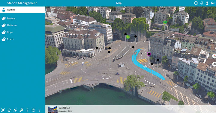
HxGN Mass Transit is a geospatial transportation infrastructure management system with 3D and AI capabilities for visualizing and analyzing transit and rail assets and operations. Built on Hexagon’s M.App Enterprise, HxGN Mass Transit provides an advanced digital twin of a city’s entire public transportation network — including tracks, stops, switches, construction sites, ticket machines, benches and garbage cans. It integrates asset and spatial data so operators can visualize and analyze an entire network with accurate and up-to-date information.
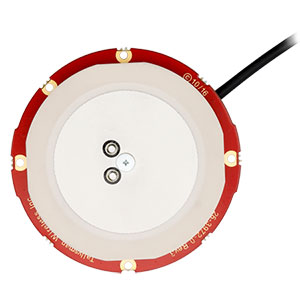
The GAJT-410MS provides anti-jamming to marine vessels. (Image: NovAtel)
The GAJT-410MS provides NovAtel’s GPS Anti-Jam Technology (GAJT) for the commercial and defense marine markets. The low SWaP variant protects civil and military operations from interference and jamming, with jammer direction-finding capabilities for enhanced situational awareness in the marine environment. The GAJT-410MS provides dynamic protection on both GPS L1 and L2 bands, as well as Galileo E1, QZSS L1 and L2, and SBAS L1 to combat intentional and unintentional interference.
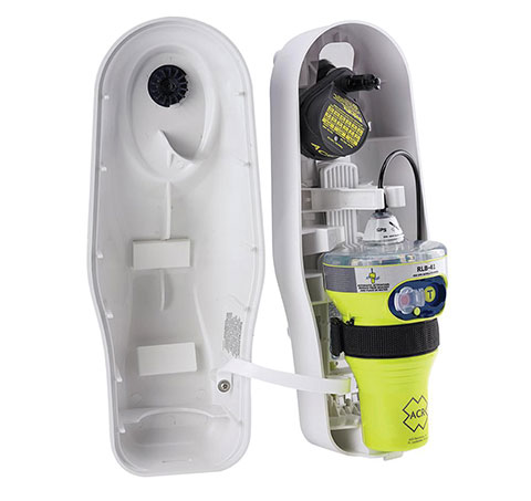
The ACR 2830 GlobalFix V4 EPIRB marine distress beacon has multiple built-in redundancies to increase chances of survival in an emergency situation. The internal GPS receiver pinpoints the user’s location, which is then transmitted on the 406-MHz distress signal. In the absence of GPS-derived coordinates, the signal can be used to triangulate the position. The beacon’s 121.5 MHz homing signal will bring local search-and-rescue forces directly to the position; an LED strobe light allows them to see the position in low light. A Category 1 Emergency Position Indicating Radio Beacon (EPIRB), the GlobalFix V4 is a float-free device that will automatically activate when submerged in water. Two self-tests monitor transmission, power and battery performance as well as GPS acquisition.
A new connected platform for rail passengers with Wi-Fi, information and entertainment content is being installed on OUIGO Spain trains through the OUIFUN portal. Passengers can connect via smartphones, tablets or PCs, access the internet on board to check email or browse the web, and enjoy entertainment content. Passengers also will be able to get travel status information in real time via an interactive map, access tourist guides or consult a menu for on-board catering. The service, provided by Moment, launched on May 10 on OUIGO’s first high-speed line in Spain connecting Madrid to Barcelona, and will gradually be extended to the whole high-speed OUIGO network.
The ANAFI Ai UAV uses 4G as its main data link between the drone and the operator. The 4G link improves data transmission and enables precise control at any distance. For BVLOS flights, it stays connected even behind obstacles. The 4G link between the drone and the user’s phone is encrypted, with a secure element protecting both software integrity and data privacy. A software development kit enables creation of custom code for flights and gives access to all sensors, including obstacle-avoidance sensors, occupancy grid and internet access.
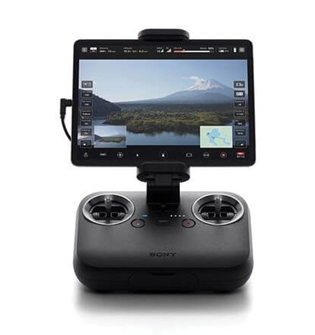
An introductory model in Sony’s new Airpeak line, the small S1 drone can be equipped with the company’s full-size mirrorless interchangeable-lens Alpha camera. Its proprietary motor, propeller, control system and sensing technology allow it to fly at high speed (a maximum speed of 55 mph) with stable wind resistance. Propulsion technology using a combination of devices developed by Sony provides wind resistance in strong wind speeds up to 44.7 mph. The Airpeak S1 includes obstacle detection, automatic flight control via sensing, and increased safety via cloud management of the aircraft.
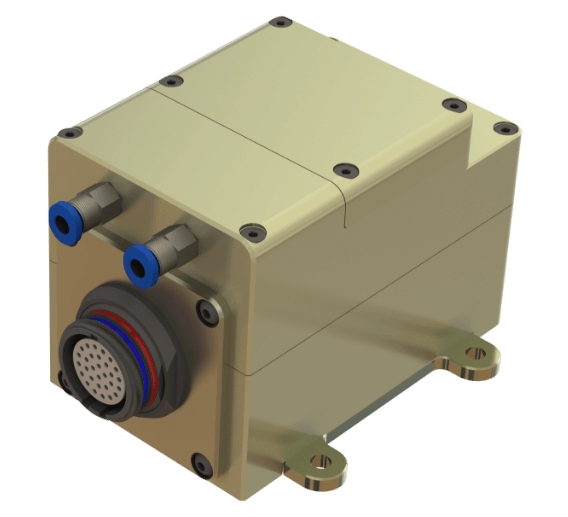
At 80 grams, George is a low SWaP certifiable solution for enterprise operations and those wishing to type certify their UAS. Built around the open-source autopilot Cube from CubePilot, George combines Cube with Design Assurance Level C (DAL-C) hardware and safety and sensor monitoring, enabling customers to meet the type certification and safety case requirements for BVLOS operations. Its triple-redundant IMU includes three accelerometers, three gyroscopes, three magnetometers and three barometers. The hardware platform is designed and built to RTCA DO-254 DAL-C and meets rigorous DO-160G and MIL-810H power and environmental qualifications.
“Seen & Heard” is a monthly feature of GPS World magazine, traveling the world to capture interesting and unusual news stories involving the GNSS/PNT industry.
Photo: IBM
Sailing new school
An autonomous ship designed to recreate the Mayflower’s historic journey across the Atlantic 400 years ago returned to the UK after developing a mechanical problem. IBM’s Mayflower Autonomous Ship (MAS) set sail on June 15 on its 3,500-mile journey from Plymouth in the UK to Massachusetts in the United States. The voyage is expected to take about three weeks, and includes collections of data on marine life and sampling for plastic waste. The 50-foot long, solar-powered trimaran is capable of speeds of up to 10 knots (18 km/h) and is being navigated by on-board artificial intelligence (AI) with information from six cameras and 50 sensors. Project leaders say the AI worked perfectly. The ship navigates with precision GNSS, inertial measurement units, radar, weather station, SATCOM and the automatic identification system.
Photo: Lt.j.g. Alexander Fairbanks/U.S. Navy
Sailing old school
U.S. Navy sailors aboard mine-countermeasures ship USS Patriot used celestial navigation to navigate an 1,100-mile voyage back to port on the western coast of Japan in July 2020. The voyage allowed the crew to improve their mariner skills as they used sextants to find their latitude and longitude and compasses to determine their heading. The exercise wasn’t entirely old school. The sailors entered the celestial measurements into a computer to pinpoint their position using the System to Estimate Latitude and Longitude Astronomically (STELLA). The combination of repeatedly inputting sextant measurements, the course and speed of the ship, and time into STELLA, provided an accurate fix of the ship’s position. For backup, Combat Information Center (CIC) watch standers followed the ship’s course with GPS. Training in celestial navigation returned to the Navy as a core competency in 2016, 17 years after the U.S. Naval Academy stopped requiring midshipmen to learn the technique.
Photo: Lt.j.g. Alexander Fairbanks/U.S. Navy
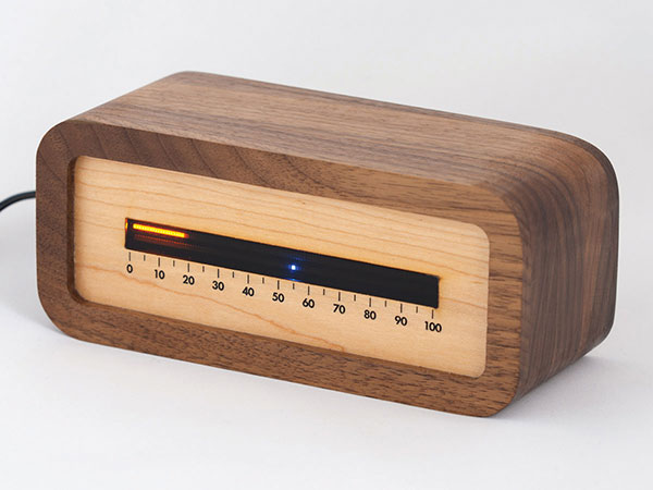
Linear clock shows sunrise, sunset
A creative technologist spent his COVID-19 downtime creating a device that uses a GNSS receiver to compute time relative to sunrise and sunset. “Since it derives time from the satellite signal, it never needs to be set, or ever adjusted for daylight saving time,” explains creator James Wilson on his webpage. The device uses satellite navigation and astronomy to show time as a progress bar measuring the percentage of the day elapsed since sunrise. A second indicator marks the time to sunset in blue.
Tracking Iran’s nuclear site
A team with Stanford University’s Center for International Security and Cooperation (CISAC) is keeping tabs on activity at Iran’s Natanz nuclear facility using BlackSky’s geospatial imagery and burst collection technology. BlackSky’s satellites provide intraday revisit capabilities, allowing CISAC’s research team to receive multiple images a day, throughout the day, rather than just one image collected at roughly the same time each day. The satellites also can capture a sequence of 20 images within minutes (burst collection) and splice them together to generate a moving sequence of activity. With BlackSky’s assistance, the research team was able to witness trucks emerging from the facility’s underground tunnels.
Spirent Federal Systems, a provider of PNT/GNSS test equipment, announced plans to fully validate the inertial interface between Spirent GNSS simulators and both Northrop Grumman legacy and modernized inertial systems under the EGI‐M program.
For years, Spirent Federal has developed inertial interface test tools in collaboration with Northrop Grumman that yield repeatable, accurate results.
Northrop Grumman’s embedded GPS/inertial navigation system (INS)‐modernization, or EGI‐M, program is developing airborne navigation capabilities with a government‐owned open architecture. The fully modernized system integrates new M‐code capable GPS receivers, provides interoperability with civil controlled air space, and implements a new resilient time capability.
“Spirent Federal has long supported testing of the Northrop Grumman family of interfaces,” said Jeff Martin, Vice President of Sales for Spirent Federal, “and our customers have always obtained precise, reliable results. Spirent Federal strives to keep abreast of the newest technology to be ready to meet the needs of industry, and this collaborative effort that includes the EGI‐M program is yet another example. Spirent is an important part of Northrop Grumman’s test solutions and this validation project acknowledges that importance.”
Spirent Federal has been providing tools for testing inertial systems for more than two decades. Available SimINERTIAL interfaces comprise various EGIs and IMUs from manufacturers of inertial sensors, including Northrop Grumman (formerly Litton), Honeywell and Atlantic Inertial Systems, as well as standardized interfaces such as STANAG.
Testing the full operational performance of GPS/inertial systems usually requires expensive and time‐consuming field testing on a moving vehicle. Spirent’s SimINERTIAL system emulates inertial sensor outputs while concurrently simulating GPS RF signals, enabling controlled, repeatable testing of EGIs and reducing the need for field trials.
UNMANNED SOLUTION, a South-Korean company based in Seoul, develops autonomous vehicles, including driverless shuttles, autonomous agricultural equipment, robots, and educational platforms. (Image: SBG Systems)
What is complementary / alternative positioning, navigation, and timing (PNT)? In this month’s cover story, five of our marketing partners share their perspective on this question and explain how their products address it.
The four global navigation satellite systems (GNSS), two regional navigation satellite systems and public and private augmentation services continue to provide exceptional levels of accuracy and reliability for positioning, navigation and timing (PNT). Yet their well-known vulnerabilities also continue to fuel the need for alternative/complementary sources of PNT data, especially for new and rapidly expanding user segments such as autonomous vehicles.
What constitutes a complementary service to GNSS for PNT and what constitutes a true alternative is partly a matter of definition and opinion. In a January report, the U.S. Department of Transportation stated
…suitable and mature technologies are available to owners and operators of critical infrastructure to access complementary PNT services as a backup to GPS. To achieve the parallel objective of resilience, as described in Executive Order (EO) 13905, that path should involve a plurality of diverse PNT technologies. Promoting critical infrastructure owner/operator use of those technologies that show strong performance, operational diversity, operational readiness, and cost-effectiveness is worthwhile. Based on this demonstration, those technologies are LF and UHF terrestrial and L-band satellite broadcasts for PNT functions with supporting fiber optic time services to transmitters/control segments. (Andrew Hansen et al., Complementary PNT and GPS Backup Technologies Demonstration Report, prepared for the Office of the Assistant Secretary for Research and Technology, Department of Transportation, January 2021, p. 195.)
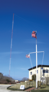
A portion of the former USCG Loran Support Unit in Wildwood, New Jersey, with its iconic Loran antenna. (Image: UrsaNav, Inc)
For this year’s Q&A on complementary / alternative PNT, I asked five companies in the GNSS/PNT space to tell us how they define the issue, what solutions they prioritize, what markets they target, and which of their products specifically address the need to make PNT more resilient.
Roger Hart: The deep adoption of the state-sponsored, space-based global navigation satellite systems (GNSS) defines them as the primary PNT source at this time. Inertial navigation, long predating GNSS, does provide an independent navigation solution but does not provide time. In today’s conversation, alternative PNT generally refers to deriving position and timing from existing signals not purposed for navigation, to ground-based location systems, and also to emerging satellite systems that operate at higher power — or out of the GNSS band — to provide a diversity of PNT sources.
David Sohn: Simply put, alternative PNT is usually anything that is not GNSS. So, this includes PNT derived from low Earth orbit (LEO) satellites; vision, radar, lidar combined with inertial measurement units (IMUs) and map matching; positioning off cellular WiFi, digital TV signals and other signals of opportunity; legacy nav aids like VORTAC, ILS, DME and eLoran; and new dedicated infrastructure positioning systems like Locata, NextNav or RFID.
Matthieu Noko: Here at SBG Systems, for 15 years we have been developing navigation systems based on smart coupling of GNSS technology and inertial sensors. From our perspective, inertial sensors as well as sensors such as odometers or DVL, combined with high-end algorithms and RAIM, build consistent alternatives to GNSS-only systems in the vast majority of outdoor applications. Inertial sensors dramatically enhance GNSS-only navigation systems, making it possible to provide navigational data during GNSS outages in urban environments or to reject false GNSS measurements due to multipath effects.
As its entry into the driverless category of the Formula Student Germany car race, AMZ modified the car it has used in competition since 2015 to be driverless. (Image: SBG Systems)
The hybridization of several technologies makes it possible to reach a sufficient reliability level for the majority of commercial applications. However, in some indoor applications or in case of intentional jamming or spoofing, a higher resiliency is required. Using visual odometry can then complement quite effectively the navigation system, although this technology is still at a research level. Compared to infrastructure-based alternative PNTs — such as WiFi, Bluetooth or ultra wideband (UWB) ranging — visual odometry has the great advantage of not requiring any infrastructure.
Jacob Amacker: GNSS remains the dominant method of PNT in terms of market applicability and performance, but there are many rival technologies that have great potential and will compete with GNSS going into the future. The most important changes in PNT will be methods of position localization that are able to replace GNSS, and we will likely see these technologies integrated into huge systems, making use of ubiquitous technologies such as lidar. Whereas GNSS still provides the most accurate timing, as systems get more complex, time synchronization becomes a bigger issue, so different methods of this need to be explored.
There are many ways of improving the navigation data overall. Most commonly an IMU and a Kalman filter will be employed to stabilize any errors in the position localization method. A Kalman filter is a method of processing data from a range of sources—say, GNSS, an IMU, and a wheel speed sensor—and using them in such a way as to arrive at the position with a greater accuracy and precision than either source alone would be able to achieve. This process, however, requires precise timing for each data stream. Therefore, one area in which alternative PNT has to compete with GNSS is timing precision. GNSS makes use of atomic clocks used on satellites that are as accurate as you will get. There are also several ways of synchronizing time. A timing system can only be as precise as the most precise clock on the network, but there have been developments, such as Precision Time Protocol (PTP) that can synchronize timings across a network of clocks over Ethernet connections. Traditionally, PPS has been used and whereas this is still very precise it is not able to compete with PTP on convenience or sophistication.
Charles Schue: The common definition these days for “alternative PNT” seems to be with respect to, or as compared to, GPS or GNSS. Even the U.S. DOT’s website speaks to PNT as related to GPS.
I used alternative, complementary and backup somewhat interchangeably during my entire career with the U.S. Coast Guard. In recent years, I injected “co-primary” into the conversation as well. Prior to GNSS becoming ubiquitous, alternative, complementary and backup were not technology-based terms, but were instead operationally based. For example, “the prudent mariner” or “the prudent aviator” should use all means at their disposal to safely navigate their platform. For the navigator, this would include visual, audible and electronic signals or aids. The solution of choice obviously was the one that provided the highest accuracy, availability, integrity and continuity. However, prudence required always checking the solution of choice against other readily available alternatives, preferably that complemented each other, to ensure safety and continuity of operations. At one time, shipboard navigators might have at their disposal Loran-C, OMEGA, GPS, INS, radar, sextant, visual bearings (such as lights and landmarks), beacons, and soundings. Similar alternatives were available on aircraft.
Although always in the mix, timing was often in the background until around 2000. Then it started to become as important as positioning and, in many areas, even more important than positioning. Today’s incredible dependence on technology, and interdependence between technologies, means that knowing your “when” has become as important as knowing your “where”.
Whatever the terminology, the definition of alternative PNT should include some key features. Firstly, we should accept that the solution of choice today is GNSS, and we should define it as primary or co-primary. Next, we should acknowledge that when the primary solution is available and trustworthy, it should always be used, or at least considered. Finally, the primary solution should continually be compared with alternatives to ensure safe and secure provision of PNT to the user. Thus, an alternative PNT solution is one that is readily available; provides an easy and seamless transition to/from the primary or other alternatives; allows continuity of operation at a possibly degraded, yet usable, level of accuracy, availability, integrity or continuity; and is dissimilar enough from alternatives to withstand the effects that might be affecting the primary solution.
Do you agree with the U.S. DOT’s assessment, cited above, of what it will take to make the national PNT much more resilient and reliable? If you do, how do your offerings fit into that framework?
RH: While there are intricate differences in the signals generated by the primary PNT systems, they are all quite similar in terms of frequency and power and are all vulnerable to the same types of interference. Achieving the most resilient solutions will require the use of alternative RF bands and non-RF sources. Having a variety of alternative PNT sources will allow users to integrate the method most applicable to their platform constraints. Integration across the various PNT sources will need time synchronization to take full advantage of the alternate PNT systems. Our offerings work concurrently with GNSS, providing simulation and testing of GNSS and alternative PNT as true complements, while also offering the ability to measure timing accuracy in real time.
DS: Yes, we agree with the DOT’s assessment. However, to be clear, the DOT does not require “LF and UHF terrestrial and L-band satellite broadcasts for PNT functions with supporting fiber-optic time services to transmitters/control segments.” It stated that to achieve resilience, systems “…should involve a plurality of diverse PNT technologies…that show strong performance, operational diversity, operational readiness and cost-effectiveness.” Their demonstrations showed that those technologies they called out meet these criteria. Our solutions have been leading this resilient approach by offering several diverse, alternative PNT references.
We have fielded time-server equipment that operates from both GNSS and eLoran. Our standard offering time servers are equipped with multiple references from GNSS, network-based time services from NTP, PTP and PTP WR; internal references from disciplined atomic clocks; wireline references from IRIG, 1PPS or ASCII time code; and LEO PNT reference from the STL signal.
(Image: SimonSkafar_E+_Getty Images)
L-band or more generally the use of geostationary satellites was until very recently the only communication link for PNT augmentation services, although these signals are weak and easily disturbed or masked, especially at high latitudes. Resilient navigation will clearly need to allow multiple downlinks for corrections such as terrestrial networks (4G/5G) or satellite-based internet. In the mid-term, we expect the correction delivery over IP to become the standard, and L-band corrections to be used as a backup only. All our high-performance products already include an NTRIP client able to handle the IP corrections very easily.
JA: This is certainly one option. Largely, it is borne out of a need to compensate for the disadvantages of GNSS. This larger range of frequencies would provide a range of satellite-borne signals that have different penetration characteristics and information carrying properties but the same core purpose. Therefore, somebody making use of such a system will be better able to receive these signals even when under obstructions. Of course, some obstructions will still be impenetrable to GNSS signals and there is a long way to go to developing a comprehensive solution that can deal with timing differences when the signals travel through objects. It is likely that some other source of timing information, for example through the proposed fiber-optic services, will be necessary to smooth out these issues. Although we will see this much-needed upgrade to cover the shortfalls of GNSS employed, many other alternatives will start to take prominence. It is difficult to say which solution will win out, and it is likely that an upgraded GNSS will continue to dominate for the next decade or two at least. In terms of our offerings, we are exploring all possibilities and keep our core technology open to any position localization method. Of course, we will welcome any new technology that is a viable and improved method of PNT.
CS: I have long been an advocate of a system-of-systems approach simply because there is no PNT solution available yet that works everywhere, under all conditions, for all users, all the time. Many solutions provide only a component of PNT: an INS provides position (the “PN”), and an atomic clock provides time (the “T”). However, an INS does not know “where” it is without initialization and updates, and an atomic clock does not know “when” it is without initialization and updates. Fiber is awesome but is not wireless. Many alternatives depend upon GPS/GNSS as a necessary input. Others are augmentations that depend upon GPS/GNSS as inputs and not direct alternatives, such as space-based or land-based augmentation systems. Some are mode-dependent — such as VOR, DME, ILS, and TACAN for aviators — and thus not useful to other modes: time/frequency, maritime, land-mobile or handheld.
So, yes, we agree with the government’s assessment that low-frequency (LF), generally referring to eLoran in the United States, is the best, very wide area, terrestrial, wireless alternative, and is an essential component of any resilient PNT framework. Irrespective of whether the implementation is Loran-C, eLoran or LFPhoenix, LF is the lowest cost terrestrial PNT solution per million square miles of coverage. All our offerings are focused on the LF portion of the resilience framework. Our offerings easily integrate with any existing PNT technology and have proven in real-world government testing their ability to survive heavy jamming and spoofing environments.
What markets and applications do you target?
RH: Spirent Federal provides simulation test solutions to U.S. government and affiliated organizations. Applications range from core GNSS receiver development to real-time, hardware-in-the-loop system integrations. We have a long history of supplying the U.S. government and contractors with first-to-market products, from Y-code, SAASM, inertial and M-code, to sensor fusion of the latest alternative signals and sensors. We provide test solutions to safety-critical applications that are expected to have the same level of operational performance both in GNSS-available and GNSS-denied environments. Providing a single test platform that can help validate performance in both environments has received positive responses from users in the autonomous vehicle industry.
DS: Aerospace and defense, data-center and communication networks, public safety, industrial control, search and rescue, and space.
Autonomous self-driving mobility solutions move people and goods at appropriate speeds in urban and campus environments. (Image: SBG Systems)
MN: SBG targets a large range of applications including from a relatively small BVLOS drone for remote operation to large hydrographic vessels or airborne survey. We divide the applications into two main categories:
Surveying and mapping, where the inertial navigation system is used to stabilize the measurements from a lidar, sonar or camera to generate high-precision maps.
Control applications, where the PNT and orientation solution is used in real time to feed autopilot or to stabilize a camera. These applications include unmanned vehicles, machine control, camera pointing and more. High resilience is then critical to ensure safe navigation.
JA: Two main applications we are targeting with alternative PNT are surveying and ADAS systems. Both of these applications often make extensive use of lidar systems. We are therefore looking at lidar-based simultaneous localization and mapping (SLAM) algorithms to aid PNT or to provide relative position localization without GNSS. In cases when GNSS is totally unavailable, it is usually possible to set up ground control points. Although these cases are limited, they give much more flexibility in options. Anticipating a future where autonomous driving is the norm and not the exception, new building projects will need to be planned with the adequate systems in place to allow for them, and this will include a system such as UWB.
CS: Our employees have been involved in the design, development, deployment or sustainment of every Loran-C and eLoran system site in the world (transmission, control or monitor) since the mid-1970s, including components of the Russian Chayka system. Our service provider and end-user technologies are operationally proven in commercial and military environments. We specifically target the maintenance and upgrade of existing systems, as well as the implementation of new systems, globally.
Which of your products directly address the need for alternative PNT?
RH: In a broad sense, Spirent offers a market-proven and innovation-driven solution portfolio for the simulation of inertial sensors through the SimINERTIAL and SimSENSOR product lines, seamlessly integrated with our GNSS simulation. Spirent is actively engaged with several alternative RF vendors to incorporate signal simulation capability and will offer an alternative RF navigation product in 2021 called SimAltNav Replay. This product will allow for concurrent GNSS and alternative RF signal simulation. Additionally, Spirent offers many other alternative PNT solutions for testing resilient systems for connected vehicles and sensor-fusion algorithms for tactical and military-grade systems. We are developing new products to incorporate an open Ethernet interface allowing for open-source Ethernet-based sensor simulation.
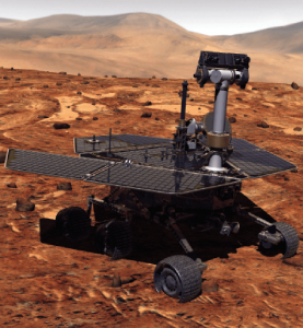
Remotely controlled rovers are used to test and practice complex tasks in Mars-like desert environments. (Artist’s Rendering: Stocktrek Images_Stocktrek Images_Getty Images)
DS: Our time servers are equipped with high-quality precise internal time references such as OCXOs or atomic clocks and then disciplined by external references such as GNSS. They are resilient because they can operate precisely for long periods in GNSS-denied situations as standalone devices in holdover mode or from multiple alternative references, such as:
network-based NTP, PTP and PTP WR time services
wireline references from IRIG, 1PPS or ASCII time code
LEO PNT reference from the STL signal
eLoran when available
They are also resilient because they detect and mitigate interference from the GNSS signal before it can corrupt the PNT solution.
Our GNSS simulators are adding alternative PNT features to provide a complete test and evaluation solution for resilient PNT systems. We have recently added INS/IMU test features and have integrated with Anritsu’s cellular test stations to evaluate and qualify combined GNSS/cellular location functions. Orolia GNSS simulators support generation of custom GNSS signals and playback of IQ waveforms, and provide complete toolsets for GNSS jamming and spoofing testing. This allows creation of the threat environment to allow evaluation of alternate PNT signals as backup or alternative to GNSS. Orolia offers an open-source framework allowing any end user to develop their own sensor plug-in leveraging the Skydel simulation engine.
Our Resilient PNT for Defense product line includes the VersaPNT, which uses alternate non-GNSS PNT sensors such as IMUs, barometers, wheel ticks, INS and non-GPS-based LEO satellites. Alternate RF navigation or non-GNSS sources of radio frequency (RF) are of interest in highly degraded or contested signal environments. Interest is focused on low-Earth-orbit (LEO) constellations. These systems offer high receiver signal power (relative to GNSS) and a secure and resilient link to augment GNSS.
MN: All our products are designed to answer to challenging GNSS conditions, starting with our Ellipse series, which includes an industrial-grade IMU capable of coping with short-term GNSS outages. Its miniature size allows integration in robotics and also makes it suitable for cost-sensitive applications. Our Apogee and Horizon series, with their navigation-grade IMUs, are the most resilient systems in the event of GNSS outages. These products reach very high-end performance in real time, but become exceptional when used with our post-processing software Qinertia. Tightly coupled algorithms make the solution capable of coping with long-term GNSS outages.
JA: We have previously created solutions using retroreflective strips for path following with driving robots. and we are also compatible with Locata’s system, a large infrastructure solution popular for automation in shipping ports. More recently, we have released an offering for UWB in an integration with Pozyx. This is perfect for GNSS-denied environments as a direct replacement for what GNSS can provide in terms of position information. We are also exploring alternative ways to synchronize clocks and get timing information. This year we have developed PTP functionality on all of our devices. Alternative PNT is going to be vital as we look to the future of navigation and thinking about how we can navigate flawlessly anywhere and address more complex environments, particularly urban areas.
CS: We are focused on the provision of terrestrial low-frequency equipment and systems for primary, co-primary, alternative, complementary and backup PNT. We provide all the products and services required to design, develop, install, certify, operate and maintain Loran-C, eLoran and LFPhoenix equipment and systems. We provide the technology to perform coverage diagrams and site surveys; all the equipment required at a transmission site; all the equipment required at a differential reference station or quality-of-service site; all the equipment required for a monitor and control site; ASF measurement and analysis equipment; and various models of end-user equipment (including receivers and antennas) for the timing/frequency, maritime, aviation, land-mobile and handheld markets.
GPS III SV05 (nicknamed Armstrong) was launched on June 17. (Photo: U.S. Space Force)
The U.S. Space Force’s Space and Missile Systems Center (SMC) transferred Satellite Control Authority of the GPS III SV05 to the 2nd Space Operations Squadron at Schriever (2 SOPS) Air Force Base on June 28. The fifth GPS III satellite — nicknamed Armstrong —was launched into space on June 17.
On June 29, GPS III SV05 received Operational Acceptance approval, marking the first GPS III SV to receive SCA handover and Operational Acceptance within 24 hours and decreasing the time from launch to on-orbit operational capability by 97 percent.
In 2020, the GPS enterprise launched two GPS III SVs in the midst of a global pandemic. According to Los Angeles Air Force Base, home of SMC, the delivery time from launch to Operational Acceptance approval has continued to shrink, with innovation and teamwork across the GPS enterprise enhancing rapid identification and elimination of redundant on-orbit verification steps.
Launch of SV05 was the first National Security Space Launch on a previously flown Falcon 9 booster, reusing the same booster that delivered GPS III SV04 to orbit in November 2020.
GPS III SV05 joins a constellation of 31 operational satellites. “The inclusion of GPS III SV05 into the operational constellation marks another significant milestone for the enterprise with 24 M-code capable satellites,” said Colonel Heather J. Anderson, transition director.
The Lockheed Martin-built GPS III SVs provide improved accuracy, advanced anti-jam capabilities, and increased resiliency for the GPS constellation and 4 billion users worldwide. GPS III SV05 will be set healthy to all global users in September, following the completion of on-orbit testing.
In one of my previous columns, I described the National Geodetic Survey’s (NGS) plans for replacing the North American Vertical Datum of 1988 (NAVD 88) with the North American-Pacific Geopotential Datum of 2022 (NAPGD2022).
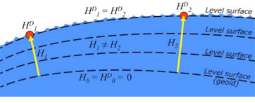
As stated in the NOAA Technical Report NOS NGS 64 Blueprint for the Modernized NSRS, Part 2: Geopotential Coordinates and Geopotential Datum, November 2017, recently revised in February 2021, orthometric heights in NAPGD2022 will be defined through ellipsoid heights and GEOID2022. This means NAPGD2022 orthometric heights will primarily be accessed through GNSS technology.
Like NAPGD2022, in the next update of the International Great Lakes Datum, denoted as IGLD (2020), the heights in the Great Lakes Region will be developed from GNSS and a gravity model. Unlike NAPGD2022, where users will be estimating GNSS-derived orthometric heights, IGLD (2020) users will be estimating GNSS-derived dynamic heights using GNSS and a gravity model.
Promote a better understanding of geodesy as a science;
Create a better appreciation of the value of geodetic surveys and thus encourage greater use of such surveys;
Promote geodetic surveys by individuals, government, and private organizations;
Foster the adoption of uniform standards and procedures for completing geodetic surveys;
Promote the processing, publishing, and disseminating of geodetic survey data and information;
Promote programs for testing, calibrating, and evaluating geodetic equipment;
Further the development and implementation of the Global Navigation Satellite System (GNSS) for geodetic, land surveying, and land information system applications;
Inform the membership of new technical developments by meetings of the association and publications in Surveying and Land Information Science (SaLIS);
Promote educational programs in geodesy, geodetic surveying, and related fields;
Cooperate with other similar organizations, both national and international, in support of the science of geodesy;
Encourage the use of geodetic surveys and mathematical coordinate systems in establishing Public Land Survey System (PLSS) corners
As stated above, AAGS cooperates with other similar organizations, both national and international, in support of the science of geodesy. AAGS is a voting member of FIG, which means AAGS has the opportunity to nominate and vote for elected officials, and develop policy that is important to all surveyors and mappers.
The theme of the FIG Working Week 2021 virtual conference was “Smart Surveyors for Land and Water Management: Challenges in a New Reality.” FIG Commission 5 focuses on meeting the highest level of accuracy for positioning and measurement (see box titled FIG Commission 5). Five 90-minute sessions described some of the efforts of FIG Commission 5.
“FIG Commission 5 focuses on meeting the highest level of accuracy for positioning and measurement. It provides the tools, techniques and procedures to educate and train surveying professionals everywhere. Appropriate methodology for data collection and processing are required to be successful in an era of global, integrated geospatial data.”
These sessions raised surveyor awareness of cutting-edge technology, techniques and procedures for using geodetic data and enhanced global cooperation and standardization in conformance with the ideals expressed by the United Nations resolution for a Global Geodetic Reference Frame. There were many good papers on positioning and measurement presented at the virtual meeting. Readers can obtain a list of presentations and papers at this website.
A paper by Jacob Heck, U.S National Geodetic Survey, and Michael Craymer, Canada Geodetic Survey titled “Updating the International Great Lakes Datum: Enabling the Integration of Water and Land Management in the Great Lakes Region” should be of interest to many U.S. and Canadian surveyors. The box below provides a link to the abstract, paper, handouts and video of the presentation.
05.1 – Managing the Land/Water Interface: WGS84 vs. the ITRS
Commission: 4 and 5
Chair: Dr. Mohd Razali Mahmud, FIG Commission 4 Chair, Malaysia
Rapporteur: Dr. Daniel Roman, FIG Commission 5 Chair, United State
Jacob Heck (U.S.) and Michael Craymer (Canada):
Updating the International Great Lakes Datum: Enabling the Integration of Water and Land Management in the Great Lakes Region (11046)
[abstract] [paper] [handouts] [video]
The International Great Lakes Datum uses dynamic heights instead of orthometric heights traditionally used for elevations on land. Figure 4 from Heck and Craymer’s FIG paper, illustrates the difference between orthometric and dynamic heights. See box titled “Figure 4 from FIG Paper by Heck and Craymer.” As described by Heck and Craymer, “The dynamic height represents the difference in potential above the reference surface and is the same at all points on a level surface. Orthometric height represents the actual physical distance above the reference surface which may change due to differences in gravity caused by the convergence of equipotential surfaces toward to the poles. Dynamic heights are therefore required for the proper management of water levels and flows in compliance with international regulations and treaties.”
Figure 4 from FIG paper by Heck and Craymer
Figure 4. Dynamic heights,HD, and orthometric heights, H. (from FIG 2021 paper by Heck and Craymer)
I would like to highlight, as described in the paper and stated in the summary, that access to the future IGLD will be primarily through GNSS techniques.
The International Great Lakes Datum provides a framework for water level management in the world’s foremost resource of surface freshwater. The current datum, IGLD (1985), is being updated and replaced by IGLD (2020). This updated datum will be fundamentally different in terms of definition and access to the datum. The datum will be identical to the new NAPGD2022 North American geopotential datum and will be compatible with the existing CGVD2013 (if not identical as well) at the reference epoch of 2020. IGLD (2020) is expected to be released in 2025 at about the same time as NAPGD2022. Access to both frames will be primarily through GNSS techniques. This will lead to more consistent heights across the entire Great Lakes region. Further information about the IGLD update can be found on the Coordinating Committee website.
This new paradigm is important for anyone who works in the Great Lakes region. Actually, it is important to anyone that surveys in the United States, because this new paradigm will also be used to access the North American-Pacific Geopotential Datum of 2022 (NAPGD2022). Anyone following my columns knows this is the future, and that the National Geodetic Survey (NGS) is leading the way in the United States by modernizing the National Spatial Reference System (NSRS).
Another section that I’d like to highlight is in the box titled “Excerpt from Heck and Craymer Paper on IGLD.”
For IGLD (2020), the geoid height, N, will be provided by GEOID2022 which will be used to define NAPGD2022 and the expected update to CGVD2013. IGLD (2020) dynamic heights will therefore be equivalent to dynamic heights in NAPGD2022 and CGVD2013 at the 2020 reference epoch. For IGLD (2020) heights of water levels, hydraulic correctors may also need to be applied.
An important advancement in the development of the new IGLD and North American datums will be the availability of an accurate crustal velocity model that can propagate ellipsoidal heights between different reference epochs. This will enable heights determined at any epoch to be propagated back to the adopted 2020 reference epoch used for IGLD (2020). This will effectively obviate the need to update the entire IGLD datum for the effects of GIA for a much longer period of time, except for incremental improvements to the velocity model and updates to the reference epoch.
It’s important for users to know that the IGLD (2020) dynamic heights will be equivalent to dynamic heights in NAPGD2022, and an accurate crustal velocity model will be used at any epoch to propagate back to the adopted 2020 reference epoch. The box titled “Determining Heights in IGLD (2020)” is an excerpt from Heck and Craymer’s FIG paper that describes the process that will be implemented for estimating GNSS-derived dynamic heights in the updated IGLD (2020).
In previous realizations of IGLD, spirit leveling was used to determine geopotential numbers which were converted directly to orthometric heights that could then be converted to dynamics heights using equation 4 (𝐻𝐷 =𝐶/𝛾45).
In the geoid-based IGLD (2020), heights will be primarily determined through GNSS techniques which provide a direct measure of ellipsoidal height. Although spirit leveling is more accurate over shorter distances, GNSS methods combined with an accurate geoid model are capable of providing more accurate heights over moderate to longer distances at a small fraction of the cost of leveling.
An orthometric height, H, above the geoid is obtained from a GNSS-derived ellipsoidal height, h, above the reference ellipsoid using the geoid height or undulation, N, of the geoid above the reference ellipsoid. This is represented by the simple equation:
𝐻 = ℎ − 𝑁 (5)
Using equations (2) – (5), the dynamic height can be obtained from the GNSS-derived ellipsoidal height using:
𝐻𝐷 =(𝑔̅ ∗ (ℎ − 𝑁))/𝛾45 (6)
For IGLD (2020), the geoid height, N, will be provided by GEOID2022 which will be used to define NAPGD2022 and the expected update to CGVD2013. IGLD (2020) dynamic heights will therefore be equivalent to dynamic heights in NAPGD2022 and CGVD2013 at the 2020 reference epoch. For IGLD (2020) heights of water levels, hydraulic correctors may also need to be applied.
An important advancement in the development of the new IGLD and North American datums will be the availability of an accurate crustal velocity model that can propagate ellipsoidal heights between different reference epochs. This will enable heights determined at any epoch to be propagated back to the adopted 2020 reference epoch used for IGLD (2020). This will effectively obviate the need to update the entire IGLD datum for the effects of GIA for a much longer period of time, except for incremental improvements to the velocity model and updates to the reference epoch.
As stated by Heck and Craymer, hydraulic correctors may also need to be applied to meet IGLD (2020) International policies, procedures and regulations. Information on IGLD (1985) hydraulic correctors can be found on NGS Geodetic Tool Kit Page.
Another paper presented at FIG Working Week that would be of interest to surveyors is a paper on establishing a geoid-based vertical datum given by Dan Roman, Chief Geodesist at NGS (see the box below). Again, the abstract, paper, handouts and video can be downloaded from the link.
05.1 – Managing the Land/Water Interface: WGS84 vs. the ITRS
Commission: 4 and 5
Chair: Dr. Mohd Razali Mahmud, FIG Commission 4 Chair, Malaysia
Rapporteur: Dr. Daniel Roman, FIG Commission 5 Chair, United State
Roman Daniel (USA): Determining an Optimal Geoid-Based Vertical Datum (10876)
[abstract] [paper] [handouts] [video]
Roman discusses the concept of establishing an International Height Reference System (IHRS) so all countries could provide physical heights across their boundaries and over the oceans (see the boxes titled “Excerpt from FIG Paper by Dan Roman” and “Summary from FIG Paper by Dan Roman “). I’ve highlighted several sections that are important to establishing a IHRS.
The IHRS is relatively recent compared to the ITRS. Ihde et al. (2017) discussed plans for unification of heights globally, which were updated more recently in Sanchez et al (2021). Just as ITRF realizations are made within the ITRS, there will be IHRF realizations made within the IHRS. The key concept here is that positions will first be realized in the ITRS and then expressed in the IHRS. This means that GNSS-accessed geodetic coordinates will determine your position in a realization of the ITRF. Using those ITRF coordinates, geopotential values will be determined from an equivalent IHRF model based above a datum of W0 = 62,636,853.4 m2 s-2. This effectively gives your position in the Earth’s gravity field, which is a physical height. In adopting such a model then, all countries might provide consistent physical heights across their national boundaries and over the oceans.
There is a great deal of activity in modernizing how geospatial data are collected, processed and maintained globally. International agreements are in place to have everyone adopt the Global Geodetic Reference Frame to facilitate geospatial data transfer. The approach will be to realize coordinates in the International Terrestrial Reference Frame and then obtain physical heights from the International Height Reference Frame. Countries may adopt any realization of the ITRF but are restricted to a single geopotential value in the IHRF – W0 = 62,636,853.4 m2 /s2. If comparisons to local tide gauges demonstrate this is not optimum for national definitions of a vertical datum, then an alternate geopotential datum can be determined based on an approach that requires supplemental information.
GNSS-observations on multiple tide gauges will establish local Mean Sea Level and any variations due to Topography of the Sea Surface. A model of the TSS would be required to remove TSS effects at tide gauges to determine the geodetic coordinates of MSL. Use of a geopotential model enhanced by locally obtained gravity data would yield the geopotential number(s) at tide gauge(s). Assuming multiple tide gauges, then an average or some statistical analysis might be made to determine the optimal geopotential value to select as a geoid.
NGS’s new modernized NSRS will be compatible with the concept of an International Height Reference Frame. As stated in Roman’s paper, a recent article by Laura Sanchez, et.al, describes a strategy for the realization of the IHRS (see box below.)
Authors: Laura Sánchez, Jonas Ågren, Jianliang Huang, Yan Ming Wang, Jaakko Mäkinen, Roland Pail, Riccardo Barzaghi, Georgios S. Vergos, Kevin Ahlgren and Qing Liu1
Abstract
In 2015, the International Association of Geodesy defined the International Height Reference System (IHRS) as the conventional gravity field-related global height system. The IHRS is a geopotential reference system co-rotating with the Earth.
Coordinates of points or objects close to or on the Earth’s surface are given by geopotential numbers C(P) referring to an equipotential surface defined by the conventional value W0 = 62,636,853.4 m2 s−2, and geocentric Cartesian coordinates X referring to the International Terrestrial Reference System (ITRS). Current efforts concentrate on an accurate, consistent, and well-defined realisation of the IHRS to provide an international standard for the precise determination of physical coordinates worldwide. Accordingly, this study focuses on the strategy for the realisation of the IHRS; i.e. the establishment of the International Height Reference Frame (IHRF). Four main aspects are considered: (1) methods for the determination of IHRF physical coordinates; (2) standards and conventions needed to ensure consistency between the definition and the realization of the reference system; (3) criteria for the IHRF reference network design and station selection; and (4) operational infrastructure to guarantee a reliable and long-term sustainability of the IHRF. A highlight of this work is the evaluation of different approaches for the determination and accuracy assessment of IHRF coordinates based on the existing resources, namely (1) global gravity models of high resolution, (2) precise regional gravity field modelling, and (3) vertical datum unification of the local height systems into the IHRF. After a detailed discussion of the advantages, current limitations, and possibilities of improvement in the coordinate determination using these options, we define a strategy for the establishment of the IHRF including data requirements, a set of minimum standards/conventions for the determination of potential coordinates, a first IHRF reference network configuration, and a proposal to create a component.
I have highlighted several statements in the box titled “FIG Working Group 5.3.” This working group is focused on issues associated with implementing vertical control based on an International Height Reference Frame (IHRF). NGS is working with these groups to ensure that the United States height system will be compatible with the rest of the world.
I encourage everyone to visit the FIG website and explore the papers given during 2021 FIG Working Week. Here is a list of the FIG Commissions. For more information can be obtained on each commission by clicking on the Commission’s title.
Before the American Congress on Surveying and Mapping (ACSM) disbanded, the four-member organization collaborated to convene annual surveying and mapping conferences in the United States. Topics similar to those presented at FIG Working Week were presented at these conferences. I became a member of ACSM in 1972 and learned a lot from attending and participating in these conferences.
Since these ACSM conferences are no longer being held, I encourage users of geospatial data and GNSS technology to participate in professional societies such as AAGS to enhance their understanding and knowledge of new technical developments in the field of geospatial positioning and measurement. As the current president of AAGS, I am biased, but a benefit of AAGS membership is access to the Surveying and Land Information Science (SaLIS)journal that publishes new technological developments related to geodesy, surveying, and mapping.