Tag: Expert Advice

  • Expert Advice: Which Is the Best GNSS Receiver?

    Expert Advice: Which Is the Best GNSS Receiver?

    Jaynata Ray
    Jaynata Ray

    By Jayanta Ray

    Aerospace GNSS receivers constitute a class apart, compared to their more popular relatives used in automotive, cell phone, or survey applications. Automotive and cell-phone receivers can sometimes provide position information even in indoor environments. The survey class of receivers provides centimeter-level accuracies. However, neither group can guarantee the reliability and integrity of the position solution, and users rely upon them at their own risk, and only in non-critical applications.

    On the other hand, an aerospace GNSS receiver not only provides decimeter-level accuracy, but it also guarantees that the position error is bounded by an integrity limit. The probability that the position error is more than the integrity limit is very rare: one in ten million times.

    Now, isn’t that the best class of GNSS receiver?

    A certified aerospace GNSS receiver stands as the keystone of the Federal Aviation Administration’s (FAA’s) ambitious NextGen Aviation program for the United States. The FAA developed NextGen to revolutionize the way an aircraft flies in the U.S airspace. In its June 2013 update report, the FAA states that “NextGen is providing major benefits to the general aviation community. The Wide-Area Augmentation System (WAAS) has improved general aviation access to more than 1,500 airports in all kinds of weather with no costly investment in ground infrastructure.”

    According to the report, by the end of the NextGen mid-term in 2020, NextGen improvements will reduce delays by 41 percent from today. The FAA estimates that by 2018, NextGen will reduce aviation fuel consumption by 1.4 billion gallons, reduce emissions by 14 million tons, and save $23 billion in costs. NextGen also has an important safety impact for air travelers.

    Tens of thousands of aircraft are already equipped with WAAS receivers, which improve the availability, accuracy, and integrity of GPS signals. Pilots take advantage of WAAS technology to fly approach procedures using Localizer Performance with Vertical Guidance (LPV) to altitudes as low as 200 feet. The FAA has published 3,123 WAAS LPV approaches as of May 2013 and expects to publish 5,218 by 2016.

    The key to NextGen is the aerospace GPS-SBAS receiver.

    How different are aerospace GNSS receivers from commercially available receivers, including high-precision receivers?

    An aerospace GPS-SBAS receiver is characterized by very high reliability, accuracy, and availability. Among these attributes, the reliability factor is the most important parameter. Misleading information from an aerospace receiver should be extremely improbable, since that can lead to hazardous or severe major consequences to the aircraft, its passengers, and flight crew.

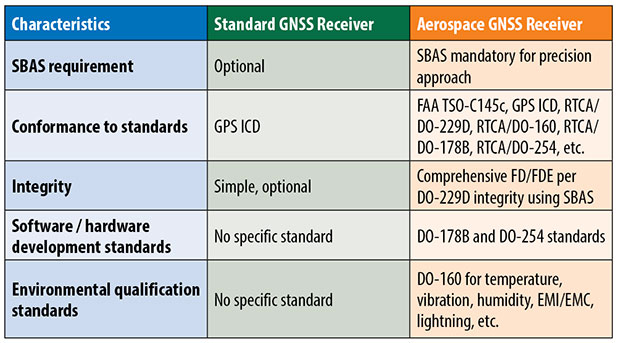
    Table 1 shows the major differences between a standard GNSS receiver and an aerospace GNSS receiver.

    Table 1 Differences between a standard GNSS receiver and an aerospace GNSS receiver.
    Table 1. Differences between a standard GNSS receiver and an aerospace GNSS receiver.

    Performance Requirements

    The DO-229D standard document — formally, the RTCA Minimum Operational Performance Standards for GPS/WAAS Airborne Equipment — specifies the minimum performance standards of an aerospace GPS-SBAS receiver. In particular, an aerospace GNSS receiver needs to meet the GPS and SBAS signal processing requirements, GPS and SBAS data/message processing requirements, satellite integrity status requirement, accuracy requirements in presence of interference, dynamic range and sensitivity requirements, and so on, as defined in DO-229D standard.

    Most importantly, the receiver must meet the Receiver Autonomous Integrity Monitoring (RAIM) requirements for en-route, terminal, non-precision and precision phases of flight of DO-229D. Additionally, the receiver must meet the fault detection, fault exclusion, missed alert, false alert, step detection, ramp detection, and other integrity-related requirements of DO-229D.

    Further, the receiver needs to meet the environmental conditions specified in DO-160 standard for temperature, temperature variation, altitude, humidity, shock, vibration, magnetic effects, voltage spike, EMI/EMC, lightning, and so on.

    Safety and Reliability Aspects

    A Functional Hazard Assessment (FHA) based on the intended function of the GPS-SBAS receiver software needs to be carried out to determine whether the receiver meets the requirements of hazardously misleading information. The safety and reliability aspects of the receiver are computed through Failure Mode and Effect Analysis (FMEA) and Fault Tree Analysis (FTA). The effects of each failure mode are determined at the system level for each operating mode of the equipment.

    RAIM.  For an aerospace GPS-SBAS receiver, RAIM is of paramount importance. The measure of protection provided by RAIM is given by Horizontal/Vertical Protection Limits (HPL/VPL). HPL is used as the protection limit for en-route, terminal, and LNAV (Non-precision approach) phases of flight and compared against the Horizontal Alert Limit (HAL) for the phase of flight. Whereas, VPL is compared against the Vertical Alert Limit (VAL) for the LNAV/VNAV and LP/LPV phase of flight.

    The most critical part of the integrity requirement is to detect a satellite failure and, if possible, to make corrective actions in addition to generating timely alerts. A Failure Detection and Exclusion algorithm, often known as FD/FDE, is to be implemented in an aerospace GNSS receiver. The effectiveness of the FD/FDE algorithm has to be tested extensively in off-line condition for availability of satellite failure detection and exclusion. Further, the algorithm has to be tested in on-line conditions as well as on a target environment. There has to be a match among the off-line,
    on-line, and on-target test results for using the algorithm in
    the GNSS receiver.

    The integrity tests on an aerospace GNSS receiver are carried out as per the guidelines in DO-229D. This requires simulation of the GPS orbit and determination of satellite visibility at more than two thousands grid points on the Earth surface and for 12 hours at 5-minute time intervals. The FD/FDE algorithm is validated at each space-time point to determine the availability of failure detection and exclusion.

    For the non-precision approach, the space-time points are arranged in terms of the HPL values and Horizontal Exclusion Limit (HEL) values and the most difficult to detect/exclude satellite is identified. Extensive Monte Carlo simulations are carried out at the selected space-time points to validate the false alert and missed alert requirements of DO-229D standard. Similar tests are carried out on the GNSS receiver for the precision approach, wherein the VPL values are considered instead of HPL values. Further, the test results of the off-line tests are validated through comprehensive on-line and on-target tests on the selected space-time points.

    Certification Aspects

    To ensure that the software and the firmware of the aerospace GNSS receiver are robust, providing adequate levels of safety and reliability, the receiver software and firmware need to be developed conforming to the software and hardware design assurance standards — DO-178B and DO-254 respectively. Based on the criticality of the end application, the design assurance should meet DO-178B and DO-254 objectives of Level A, B, or C criticality.

    An aerospace GNSS receiver needs to be certified by the FAA (or other competent authorities in other countries) for airworthiness. The FAA gets involved in the certification process right from the planning stage and oversees the compliance of the entire development process as per DO-178B and DO-254 standards. The aerospace GNSS receiver software and firmware undergo extensive verification and validation processes. Further, the GNSS receiver is subjected to all the functional and environmental tests as per DO-229D and DO-160 standards respectively under FAA supervision. Only after the successful completion of all the software, hardware, and systems tests, the receiver is certified by the FAA for airworthiness through Technical Standard Order TSO-C145 Authorization (TSOA).

    Conclusion

    Aerospace GNSS receivers, by virtue of their inherent safety, reliability, and integrity, are far more suitable for critical applications, where an error could have hazardous or catastrophic consequences. These receivers must be used in commercial transport aircraft, business jets, general aviation aircraft, gliders, experimental aircraft, balloon, and so on. Further, in airport surface vehicles and mass-transport vehicles such as high-speed trains, trams, and unmanned autonomous vehicles of all sorts, whether ground or air, receivers similar to aerospace GNSS receivers should be used for navigation and surveillance purposes.


    Jaynata Ray received his Ph.D. from the University of Calgary. He has worked in the GPS field since 1992, and is group manager at Accord Software and Systems in Bangalore, India. He is a member of GPS World’s Editorial Advisory Board.

  • Expert Advice: Get Sporty

    Expert Advice: Get Sporty

    mountain bikers, with navigation device

    By Mark Sampson

    In recent years, the sporting world has seen an explosion in the use of GPS. You will rarely spot a runner or cyclist on the road without either a smartphone strapped to their arm or a dedicated GPS device clamped to their handlebars, tracking their every move.

    The amount of information that the modern sportsperson — from casual amateur to full-time professional — logs, analyzes, and shares is phenomenal. There are now dozens of ways of uploading data for the whole world to share and study.

    As more manufacturers come to this market with the hope of capturing a share of it, they face the challenge of effectively developing and then testing their devices. Among many factors to consider, new products must have capability for local constellations such as BeiDou, GLONASS, and QZSS, not just GPS alone. New market entrants won’t have the same budget as the established big players, and constantly traveling to China or Japan to try out a new gadget will escalate costs to an unsustainable degree.

    Then there’s the issue of getting out into the kind of environment in which you imagine your new sporting GPS device will be put to use. In many cases this will be remote: forests, hills, and mountains. Stepping outside to the office car park does not constitute a sufficient test for satellite acquisition and retention. Neither does simply driving the commute route home with it.

    A GPS simulator or replay device allows for bench testing, but such devices are expensive. They might not actually fulfill your testing requirements, either: a traditional GPS simulator outputs its scenarios based on constellation modeling, either as a perfect signal or one that has simulated multipath. But you need to genuinely know how your new product will operate through, say, a forest on a downhill mountain bike run, or during a city marathon through urban canyons, or on a trail under wet trees. Adventure sport participants want to record their achievements wherever they go.

    How do you obtain this kind of realistic scenario? It will require the use of a GNSS recorder, and in an ideal world you would lend it to someone who actually does some of this stuff. Perhaps one of your colleagues is an (insane) downhill skier — who better to capture exactly that type of data, which you can replay back in a nice warm lab?

    The trouble is that a person of this sporting ilk will be unwilling or unable to carry bulky equipment that weighs several kilos. It will slow them down, so a GNSS recorder that can be easily carried without affecting the sporting activity is essential. It has to be easy to use: self-contained, with a battery that will last a couple of hours, and with one big button to start and stop recording. The user shouldn’t need any training in its operation. And ideally, it won’t need a large ground-plane antenna to capture usable data; a well-designed unit will employ a sensitive GPS engine allowing for as complete a signal as possible to be logged through a standard passive antenna.

    Looking further afield, other industries will soon be seeking a device with this level of convenience. For instance, agricultural and automotive manufacturers want the ability to send test engineers out to record drive-cycle tests easily and in a variety of vehicles. Additional features, such as controlled area network (CAN) and inertial sensor logging, synchronized with the GNSS data, will also find favor.

    The nature of the simulation market is changing: increasing numbers of developers need not just a traditional constellation simulator, but rather a replay device that is feature-rich and that doesn’t cost the earth.
    Economies of scale will likely dictate the way that this develops, and GNSS simulation will no longer be the specialist and exclusive field it once was.


    Mark Sampson is the LabSat product manager for  RaceLogic, based in Buckingham, UK.

  • Expert Advice: Laser Reflectors to Ride on Board GPS III

    Expert Advice: Laser Reflectors to Ride on Board GPS III

    From left: James J. Miller and John LaBrecque, NASA Headquarters; A.J. Oria, Overlook Systems Technologies
    From left: James J. Miller and John LaBrecque, NASA Headquarters; A.J. Oria, Overlook Systems Technologies

    By James J. Miller and John LaBrecque, NASA Headquarters, and A.J. Oria, Overlook Systems Technologies, Inc.

    Satellite laser ranging (SLR) and the results of combining SLR with GPS in the future will translate into significant performance advancements for generations to come, once it is fully implemented as part of the GPS III architecture. Simply put, SLR techniques will improve GPS signal performance by enhancing the accuracy of GPS orbit and clock estimates, allowing for the correction of systematic errors and limitations inherent in current GPS radiometric solutions.

    This will produce higher levels of positioning and timing as new information is processed and used to update orbital models and reference frames over a period of time. Eventually this will enable user accuracy in the centimeter range, orders of magnitude better than the 1-meter average user-range accuracies accessed today. Every GNSS constellation under development will provide for SLR, because not doing so would limit their systematic accuracy and diminish the potential of their PNT services.

    This SLR initiative progressed over the past decade from technical engineering exchanges to senior-level reviews and policy deliberations under the aegis of the PNT EXCOM (see Sidebar), with GPS III now poised to have laser retro-reflector arrays (LRAs) placed on board all space vehicles, beginning with number 9 (GPS-III-SV9).

    The National Aeronautics and Space Administration (NASA), National Geospatial-Intelligence Agency (NGA), National Oceanic and Atmospheric Administration (NOAA), and the U.S. Geological Survey (USGS), among others, strongly support the decision by Air Force Space Command to proceed with the placement of LRAs on board GPS III satellites to enable SLR. These agencies will work together to ensure that the derived science benefits all PNT EXCOM agencies and our many constituents and users around the world.

    How Satellite Laser Ranging Works

    SLR to any orbiting body involves firing repetitive laser pulses towards an object equipped with some form of LRA. The laser roundtrip time is then translated into distance or range measurements (Figure 1). In our case, SLR data collected from lasing to GPS and other GNSS constellations is compared with radiometric data collected at GPS/GNSS ground monitoring stations.

    Figure 1. SLR operations description.
    Figure 1. SLR operations description.

    Radiometric monitoring and SLR each have their respective strengths. Radiometric monitoring stations are inexpensive and can be densely deployed, but are susceptible to systematic errors that cannot easily be identified. SLR is a high-accuracy method, independent of radiometric positioning, that can be used to identify some of these systematic errors. The two techniques in concert will provide more accuracy to the determination of satellite orbits and clocks, strengthening the societal benefits of GPS through improved performance and more precise applications over time.

    Societal Benefits of Space Geodesy

    Geodesy is the science of the Earth’s shape, gravity, and rotation, and their variations over time. Modern geodetic measurements rely upon GNSS technology and techniques to understand and respond to evolving geo-hazards such as earthquakes, volcanic eruptions, debris flows, landslides, land subsidence, sea-level change, tsunamis, floods, storm surges, hurricanes, and extreme weather. In recent years, GPS radio occultation data from satellites is used by weather services to improve the accuracy of forecasts. Other benefits include the use of regional differential networks to monitor crustal movements in near real time, and guide farm machinery and construction equipment with centimeter-level accuracies.

    An essential element is the ability to relate geodetic measurements to one another in space and time through a stable and accurate reference frame. Most global terrestrial reference systems set their origin to the Earth’s center of mass or geocenter. Precise knowledge of the reference frame geocenter and its relative change are needed to study regional and global sea-level fluctuations and ocean-climate cycles like El Niño, the North Atlantic Oscillation, and the Pacific Decadal Oscillation.

    Reference Frames

    GPS satellite ephemerides are derived from ranging based on pseudorandom noise signals and carrier-phase variations, referenced to onboard atomic clocks and a ground network of GPS monitor stations expressed in the World Geodetic System 1984 (WGS 84) reference frame. The WGS 84 reference frame is determined using the analysis of GPS satellites, and must be periodically updated by the National Geospatial-Intelligence Agency (NGA) due to geophysical processes such as tectonic-plate motion. NGA works to maintain the tightest alignment between the WGS 84 and the International Terrestrial Reference Frame (ITRF) using GPS reference sites common to both.

    The more ambitious ITRF is obtained using a global network of instrumentation — GPS, SLR, Very Long Baseline Interferometry (VLBI), and Doppler Orbitography and Radio-positioning Integrated by Satellite (DORIS) — and geodetic satellites such as LAGEOS and LARES. These data are gathered and analyzed through an international cooperative effort by the services of the International Association of Geodesy (IAG) within the framework of the Global Geodetic Observing System (GGOS) (Figure 2).

    Figure 2. Structure and products of the Global Geodetic Observing System related to GPS performance.
    Figure 2. Structure and products of the Global Geodetic Observing System related to GPS performance.

    The integration of SLR and radiometric tracking of all GNSS constellations will improve multi-GNSS performance and interoperability as tools and techniques are co-located and data combined into various products that enable PNT service providers to improve system models.

    Geodetic Requirements. GPS is a critical component in the determination of the ITRF geodetic reference frame and serves as the principal means of positioning relative to the reference frame. Though the current accuracy of the ITRF and WGS 84 reference frames marginally meets most current operational requirements, emerging scientific requirements in Earth observation demand more accuracy than core geodetic systems, including GPS and the ITRF, can deliver.

    There is thus a growing GPS capability gap that can only be met with systematic improvements such as SLR will enable. In this manner, today’s scientific needs for positioning and timing often become tomorrow’s operational capabilities. If GPS is to continue as the primary geodetic reference system, we must ensure that GPS continues to evolve its system accuracy as well (Figure 3).

    Figure 3. Evolution of GPS accuracy versus civil and scientific requirements assuming a factor of ten per decade improvement in accuracy.
    Figure 3. Evolution of GPS accuracy versus civil and scientific requirements assuming a factor of ten per decade improvement in accuracy.

    Presently, the accuracy of both the ITRF and the WGS 84 is estimated to be on the order of 1 part per billion (6.4 millimeters at the Earth’s surface), with observed regional drifts on the order of 1.8 mm/year, and errors in the colocation of geodetic stations exceeding 5 mm/year. There is also little to verify this estimated accuracy of the reference frames, because successive estimates of the ITRF are retrospective and utilize the same historical data sets, except for the addition of more recent data and new analysis approaches. All determinations of the ITRF are therefore inter-related and not independent, allowing some errors to remain embedded.

    Although such drifts and errors are acceptable for meter-level positioning, we must address these significant instabilities if we are to meet the growing geodetic requirements demanded by science and society. The GGOS and the National Research Council have called for a significant improvement in the accuracy and stability of the ITRF, including the goal for 1 mm of accuracy and 0.1 mm/year of stability.

    Getting Laser Reflector Arrays aboard GPS III

    In 2006, a working group of representatives from multiple U.S. civil and military government agencies identified a set of anticipated geodetic requirements for GPS to meet future geodesy and science needs. An analysis of alternatives (AoA) concluded that the only practical solution to correct for systematic errors in satellite coordinates and reference frames is optical laser ranging, as has been demonstrated on board GPS block IIA SV-35 and -36. These were equipped with LRAs thanks to the effort of Ron Beard of the U.S. Naval Research Laboratory (NRL).

    In 2007, the geodetic requirements and AoA were submitted to the GPS Interagency Forum for Operational Requirements (IFOR), along with formal endorsement letters from NASA, NGA, NOAA, and USGS. The goal of the GPS IFOR is to ensure that new features on GPS adhere to U.S. PNT Policy objectives, and that any proposed technical enhancements do not degrade core GPS performance, schedule, signals, or services. Between 2007 and 2012, interagency IFOR discussions and studies continued and subsequently were elevated to a special multi-agency study group led by AFSPC and NASA. In December 2012, after reviewing the results of these technical deliberations, NASA Administrator C. Bolden, AFSPC Commander Gen Shelton, and U.S. Strategic Command’s Gen Kehler agreed on a plan for installation of LRAs on all GPS III vehicles beginning with SV9.

    Laser-Ranging Operations

    GPS laser ranging will be accomplished through the International Laser Ranging Service (ILRS), and NASA will ensure all operations adhere to a set of standards and procedures. All ILRS GPS laser ranging will use 532- or 1064-nanometer wavelengths, and the reflectivity of LRAs will be optimized for these two “colors.” To support operations and accommodate this level of control and situational awareness, the ILRS has defined minimum standards for GNSS LRA cross-sections to optimize ranging to the satellites by ILRS stations.

    The design of the LRA for GPS III, funded by NASA and currently being developed by the NRL, easily exceeds the ILRS recommended standards. Some satellites tracked by the ILRS are to be ranged subject to certain basic restrictions and conditions to ensure the science data gained is optimal for all stakeholders. The ILRS has developed policies and procedures for controlled tracking, and laser ranging to GPS III will be performed on a schedule issued by the ILRS Central Bureau located at the NASA Goddard Space Flight Center in Greenbelt, Maryland.

    The laser-ranging schedule will be coordinated considering ground-network capabilities, GPS operational requirements, and the tracking frequency required for accurate orbit determination. Only certified/approved ILRS stations will be authorized to perform laser ranging following a predetermined assessment, using approved laser-ranging stations operating within set technical parameters (color, power, and so on). The ILRS will issue digital keys once confirmation is received that all conditions have been met, with AFSPC and NASA maintaining a role.

    Summary

    A positive way forward has been established to allow for the implementation of laser ranging to the GPS-III constellation beginning with SV-9 in the 2019 timeframe. The laser ranging to GPS III, followed by post-processed analysis and mitigation of systemic errors, will contribute significantly to achieving the goal of a more accurate ITRF. These applications will also be augmented by an ongoing and significant international investment in the global geodetic infrastructure of the GGOS observing networks and analysis systems. Laser ranging of GPS III will also encourage further international investments and industry innovations as higher precisions are further introduced to the world community.


    Sidebar

    The PNT EXCOM

    The U.S. National Space Based, Positioning, Navigation, and Timing (PNT) Policy, formally unveiled in December 2004 and supported through two administrations, strengthened GPS by creating a deputy-secretary-level PNT Executive Committee (EXCOM) to coordinate federal agency oversight of this critical national asset. The PNT EXCOM is co-chaired by the Department of Defense (DoD) and Department of Transportation (DOT), with representation by the deputy secretaries, or their equivalents, from other agencies and departments. The PNT Policy maintains the U.S. Air Force (USAF) as the DoD Executive Agent for Space.

    This policy also designated newer responsibilities for other agencies. The NASA administrator, in coordination with the Department of Commerce and DOT, is responsible for developing requirements for the use of GPS and its augmentations in support of civil space systems. This level of collaboration is enabled by high-level interagency stakeholder discussions on all aspects of civil GPS activities. This is vital in the age of GPS modernization among other emerging constellations, as it allows individual PNT EXCOM agencies to develop and fund new capabilities. This multi-agency collaboration is very appropriate for GPS, since PNT is a suite of services used by all federal agencies to serve the public, providing greater safety, efficiency, and economy for a multitude of governmental missions.

    Collaboration through the PNT policy has allowed NASA to optimize the use of GPS-based PNT services to fulfill a variety of science missions with ever-expanding societal benefits, ranging from space operations, exploration, Earth observation, and weather forecasting, to all manner of environmental monitoring including ice-melt and sea-level fluctuations. These data are increasingly important for governments to be able to plan for and respond to changes affecting human health, economy, and security. NASA therefore continues to work closely with the USAF and other PNT EXCOM agencies to improve the performance of GPS and its products through science initiatives.

    One such initiative is known as GPS Satellite Laser Ranging (SLR), and is described here, along with its implementation aboard GPS III satellites.


    Acknowledgments

    The authors thank these individuals for their contributions in developing a way forward for the implementation of LRAs on GPS III, clearly showing the high level of interagency interest and coordination required to make this initiative happen overly nearly a decade of work. We are especially grateful to the U.S. Department of Defense, and in particular to U.S. Air Force Space Commander General Shelton, for leadership and support in enabling NASA and our partners to realize this important contribution to GPS in years to come: Honorable Charles Bolden, Honorable Lori Garver, Gen William Shelton, Gen Robert Kehler, Letitia Long, Maj Gen Martin Whelan, Chris Scolese, Badri Younes, Michael Freilich, Jack Kaye, Barbara Adde, Norm Weinberg, Craig Dobson, Mike Moreau, David Carter, Stephen Merkowitz, Yoaz Bar-Sever, Scott Pace, Ray Yelle, Scott Wetzel, Major Janelle Koch, Col (Ret.) David Buckman, Col (Ret.) Allan Ballenger, Col (Ret.) David Madden, Col (Ret.) Bernard Gruber, Col James Puhek, Steve Malys, Thomas Johnson, Ron Beard, Linda Thomas, Mark Davis, Larry Hothem, Ken Hudnut, Hank Skalski, James Slater, Vaughn Standley, Mike Pearlman, Erricos Pavlis, Kirk Lewis, Maj Gen (Ret.) Robert Rosenberg, and the National Space-Based PNT Advisory Board co-chaired by Honorable James Schlesinger and Col (Ret.) Bradford Parkinson.


    James J. Miller is deputy director of the Policy & Strategic Communications Division with the Space Communications and Navigation (SCaN) Program at NASA.  He is a commercial pilot with master’s degrees in public administration from Southern Illinois University and international policy and practice from George Washington University.

    John LaBrecque is lead of the Earth Surface and Interior Focus Area within NASA’s Science Mission Directorate, managing NASA’s Global Geodetic Network that provides PNT products in support of NASA’s Earth Observation program. He received his doctorate in marine geophysics from Columbia University.

    A.J. Oria works for Overlook Systems Technologies, Inc., supporting NASA headquarters in the area of GPS and PNT technology. He has a Ph.D. in astronautics and space engineering from Cranfield University, UK.


    Related article (PDF):Innovation: Laser Ranging to GPS Satellites with Centimeter Accuracy,” by John J. Degnan and Erricos C. Pavlis, published in GPS World, September 1994.

  • Expert Advice: Looking Back to the Early Days of GPS

    Len Jacobson
    Len Jacobson

    By Len Jacobson

    Besides my family and friends, two major influences have guided my life. One is GPS, and the other is flying, although I’m not a pilot. Most of the flying was on business trips for GPS. I’ve been writing a book about my experiences and how I helped in a small way to bring GPS to the world. I estimate I’ve spent about eight months aboard airplanes, logging almost 2.5 million miles. During that time, I visited many places throughout the world, acting as a catalyst to promote the use of GPS and to obtain GPS business for my employers and for myself. I kept an extensive log of my travels and it enabled me to recreate much of what happened, and my impressions of why events occurred.

    In 1968, after two engineering degrees and five years working in communications systems, I met a business development director from Magnavox, which had teamed with Hughes Aircraft, where I worked, on a study contract. We both attended a briefing on the contract status; that day was my first encounter with what would become known as GPS.

    I attended one more meeting about the 621B satellite program. The U.S. Air Force had no funding for a full-up 621B, so instead it focused on proving that the technology was viable. We were asked to bid on supplying a receiver that would precisely measure a half-mile of cable using a spread-spectrum signal. I vividly recall a Hughes VP stating that 621B would never go anywhere, and besides, Hughes was only interested in building synchronous satellites. Our 621B competitor, TRW, agreed take the follow-on contract. TRW was acquired by Northrop Grumman in 2002. The Air Force felt it needed two competitors in case one failed, so it offered a second contract to Magnavox. The company took the contract, which became its first hardware entry in the world of GPS.

    Before long, I received an offer from Magnavox to join the world’s leading experts on implementing anti-jam communications systems using then-classified, direct-sequence spread-spectrum technology. Magnavox had been working in the field since it was formed in the early 1960s, building the first anti-jam modems for the Initial Defense Communications Satellite Program (IDCSP) and now pursuing a follow-on program. Its main business areas were satcom, tactical communications, and positioning programs such as the 621B receiver. There also was a group building Transit satellite receivers for the Navy. Transit was really the first navigation satellite, growing out of experiments at Johns Hopkins University Applied Physics Lab, using Sputnik signals to determine one’s position on Earth by tracking the Doppler signal of a satellite in a known orbit. Besides the Naval Research Lab, Magnavox built the only Timation receivers, an early competitor to GPS for solving military positioning needs using a satellite system.

    While I was still working at Magnavox on satcom, the 621B receiver was completed and we proved you could use a spread-spectrum signal to accurately measure distance. Once again, the Air Force did not have funds to launch navigation satellites so it proceeded with a new effort called “621B User Equipment Definition and Experiments Program.” The prime contractor was Grumman Aircraft. The idea was to put four transmitters on the ground and have an aircraft with a receiver fly over them and try to determine the aircraft’s position. The signals were to look as if they came from four satellites and were received by an antenna on the bottom of the plane. Grumman decided to use a receiver built by Hazeltine, which had some experience in spread spectrum but nowhere near as much as Magnavox. For this reason, the Air Force leased another receiver from us, asking how much? We came up with the number $450,000, our development and build cost. They agreed, and we called the receiver the MX450. It flew beside the Hazeltine receiver on the NC-135 aircraft at the White Sands Missile Range. Most of the usable test data came from the MX450, showing residual errors between the aircraft solution and the range tracking system to be less than five feet. This data was crucial in getting DoD approval in 1973 to proceed with Phase 1 of GPS. But we should have called it the MX495 because we overran the cost by $45,000.

    A Tale of Two Contracts

    The procurement for Phase 1 GPS came together as two major contracts. There would be a small number of satellites that Rockwell would win competitively and would lead to many years and billions of dollars in future GPS satellites, as it became part of Boeing Corp. ITT would build its own payload and go on to be the major supplier of GPS payloads to this day. The other contract, a study contract, was awarded to three companies: General Dynamics Electronics (GDE), Philco-Ford, and Grumman. Two of the contractors performing that study, which ended in proposals for the design of the ground network and several types of user equipment (GPS receivers), would be chosen to create the designs. Then one of the two would be selected to actually implement Phase 1 of GPS.

    After the first round down-select, we were now playing in the big leagues, GDE/Magnavox against Philco/TRW. The Philco leader, Jim Spilker, and our guru, Charlie Cahn, had to work together along with Rockwell engineers to define a common signal for GPS. The product of their work is still in use as it was defined then, at least for the civil C/A GPS signal. There were tradeoffs and compromises. The length of the short code was a contentious issue. TRW had built a 512-bit correlator, and Philco pushed that for the C/A-code. Cahn wanted 2048 bits to minimize inter-satellite signal interference. They compromised on 1024 bits. Charlie wanted a serially transmitted short code/long code for the military signal to enable long-code acquisition, a technique we had used in all our modems. But Spilker pushed for the codes to be transmitted in phase quadrature, a more elegant solution that prevailed. The need for a short code arose because the receiver could not acquire the long military signal unless it knew time to microseconds accuracy. The military code was very, very long. By first acquiring the short, repetitive C/A signal, the receiver could read its data and determine time close enough to make a long-code acquisition search practical.

    The GDE/Magnavox team won the Phase 1 contract, and we were developing the first military and civil GPS user equipment (UE). Our Phase 1 UE contract included quantities of a 4-channel, high dynamics set for the F-4 fighter aircraft; a 2-channel aircraft set for the bigger and slower C-141 and helicopters; a manpack; and a civil aircraft set that looked like a TACAN and used only the C/A GPS signal. The three aircraft sets were called the X-set, Y-set and Z-set, respectively. Before long, Col. Brad Parkinson, director of the Joint Program Office, decided that there should also be a competitive high-dynamics set and another manpack, and awarded a contract to Texas Instruments. The USAF avionics laboratory wanted a piece of the GPS action so it awarded a what it called a “high technology” GPS UE contract to Rockwell Collins.

    For various reasons, many not of its own making, Collins eventually became the number-one supplier of military GPS UE, long after Magnavox faded from the scene. (Hughes and then Raytheon eventually acquired the Magnavox GPS crew, where some of my former colleagues still work today.) The Collins unit flew in the C-141. Our X-set flew in a pod under the F-4. The complement of equipment, GPS receiver, navigation computer, power supply, and so on, was too big to be installed into the aircraft, so it was housed in the pod.

    Building the Crew

    To staff the contract required hiring many new engineers. We scoured our competitors and prior employers that had people experienced in the needed hardware and software disciplines, and were able to create a crew that went on to become major contributors to GPS developments for decades. Some started their own GPS companies, like Min Kao who, with Garry Burrel of King radio, later became the MIN and GAR in GARMIN. Another GPS company started by Magnavox people is CAST Navigation, a GPS simulator manufacturer.

    The Magnavox Marine Division developed commercial Transit receiver and integrated shipboard navigation systems and survey systems. Later on, it pioneered GPS-based marine navigation systems and eventually split off into another company called Navcom, formed by Jim Litton, which later became part of John Deere. Several notable GPS experts from that Magnavox cadre like Tom Stansell, Ron Hatch (still with Navcom), and Jerry Knight are actively consulting today. So with all modesty, I have to say that I too was part of that original group who can claim some degree of fatherhood for GPS user equipment and receivers.

    Over the next several years, I became an ambassador for GPS, traveling the world, particularly to visit potential military GPS users in NATO and at other allies. In the late 1970s, Magnavox and Collins were awarded the Phase 2 user-equipment developments. About a year before the production contract was awarded to Collins, I had left Magnavox to join Interstate Electronics (IEC), now a major part of L-3 Communications, to lead its efforts to become a military GPS user-equipment supplier. IEC had a unique technology for tracking submarine-launched ballistic missiles using a GPS translator tracking system. We succeeded in applying it to the DOD test ranges and for Trident missile tracking and submarine navigation. In my later years there, we eventually miniaturized the GPS receiver to the point where it could be applied to guiding missiles and projectiles.

    After nine years at IEC, I decided to go out on my own as a consultant and formed Global Systems and Marketing, Inc. For the next 20 years I worked on various assignments from most of the major GPS companies and several small businesses that were trying to find a position in the GPS market. I also participated as an expert witness in many legal cases involving GPS, from patent disputes to accident reconstruction to parolee tracking.

    Looking back now from the beginning of my retirement, I can obviously say I’ve learned a lot. Two things stick out in my mind:

    • Never believe the schedule and budget anyone offers up, because new developments will likely take longer and cost more than originally estimated;
    • When you stop being better, you stop being good.

    I know the future holds more miraculous applications of GNSS technology because of all the brilliant, innovative people working in the field that I have met, and those that I haven’t met but have read about in places like GPS World. You are all very fortunate to be part of what I call the most important dual-use system (after the Internet) ever invented.


    Len Jacobson is a retired GPS consultant, having worked in the field since 1968. He is still active in the Institute of Navigation, having been Western regional vice president twice and held leadership roles in several of its conferences. He lives in Long Beach, California. Visit his site at www.lenjacobson.com.

  • Expert Advice: The Chip-Scale Combinatorial Atomic Navigator

    Expert Advice: The Chip-Scale Combinatorial Atomic Navigator

    Andrei Shkel, Defense Advanced Research Projects Agency (DARPA)
    Andrei Shkel, Defense Advanced Research Projects Agency (DARPA) Photo: Andrei Shkel, Defense Advanced Research Projects Agency (DARPA)

    By Andrei Shkel, Defense Advanced Research Projects Agency (DARPA)

    Future breakthroughs in microtechnology for positioning, navigation, and timing (PNT) will likely rely on yet-to-be-exploited physics, new materials, highly specialized fabrication technologies, batch assembly techniques, selective wafer-level trimming and polishing, a combination of passive and active calibration techniques strategically implemented right on-chip, and introduction of innovative test technologies.

    Such microtechnology advances for PNT are sought because reliance on satellite-based GPS for precision PNT information, which is critical to the conduct of many types of military operations and the performance of a wide range of military weapon systems, can mean dependence on a resource that may become inaccessible, whether as a result of some type of component or overall system malfunction or as a consequence of deliberate enemy action. The goal of the DARPA micro-PNT portfolio of programs is to develop micro-technology for self-contained, chip-scale inertial navigation and precision guidance that would effectively eliminate the dependence on GPS while enabling uncompromised navigation and guidance capabilities for advanced munitions and various military platforms, under a wide range of operation conditions.

    In 2012, under the project name C-SCAN, DARPA solicited innovative research proposals in the area of co-integration of inertial sensors with dissimilar physics of operation in a single micro-scale inertial measurement unit (IMU). This solicitation is an integral part of DARPA’s microtechnology for positioning, navigation, and timing (micro-PNT) portfolio of programs. The overarching objective of the micro-PNT portfolio is to develop technologies for self-contained chip-scale inertial navigation and precision guidance that could effectively eliminate the dependence on GPS or any other external signals and enable uncompromised navigation and guidance capabilities for advanced munitions, mid- and long-range missiles, and various military platforms under a wide range of operating conditions. The micro-PNT program includes a number of important specific efforts that focus on development of precision timing devices, inertial sensors, and microsystems. C-SCAN leverages the results of these efforts and expands the scope of the micro-PNT program.

    In this context, the program sought to address challenges associated with the long-term drift, dynamic range, and start-up time of chip-scale components for positioning, targeting, navigation, and guidance tasks. Specific interest lies in the development of a Chip-Scale Combinatorial Atomic Navigator (C-SCAN) that combines inertial sensors with dissimilar, but complementary, physics of operation into a single microsystem. The main objectives of the C-SCAN program are to:

    • explore miniaturization and co-fabrication of atomic sensors with high-performance solid-state inertial sensors, and
    • develop combinatorial algorithms and architectures that seamlessly co-integrate components with dissimilar physics in a single ensemble.

    The deliverable is a miniature IMU that co-integrates atomic and solid-state inertial sensors in a single microsystem with a volume of no more than 20 cubic centimeters (20 cc) and power consumption of no more than 1 Watt (1 W). The performance of C-SCAN is expected to be above and beyond what is currently available, combining a high resolution of motion detection (10-4 deg/hour for rotation and 10-6 g for linear acceleration), exceptional long-term bias and scale-factor stability (1 ppm with respect to the full-scale of operation), and start-up time performance orders of magnitude better than available today (less than 10 seconds from cold start).

    To meet these objectives, the C-SCAN program expects to develop a complete IMU comprised of combinatorial gyroscopes and accelerometers with the following characteristics: 10-4 deg/hour and 10-6 g bias stability, 5·10-4 deg/√hour angle random walk (ARW) and 5·10-4 m/sec/√hour Velocity Random Walk (VRW), 1 ppm bias and scale-factor drift characteristics of 40 Hz (or ~15,000 deg/sec), and 1,000 g range of operation, respectively.

    Figure 1. C-SCAN conceptual implementation.
    Figure 1. C-SCAN conceptual implementation. Photo: Andrei Shkel, Defense Advanced Research Projects Agency (DARPA)

    The C-SCAN module will have three axes of rotation, as well as three axes of acceleration sensitivity. The misalignment between the axes of sensitivity in C-SCAN is not to exceed 10-4 radians when operating in a harsh military environment. The operational environments of interest are:

    • in-operation exposure to temperatures varying from -55ºC to +85ºC,
    • in-operation exposure to mechanical vibrations from 5 Hz to 5 kHz with an average amplitude 5 g, and
    • device survivability and subsequent normal operation after exposure to
      • 15,000 g shock exerted in less than 1 second,
      • a peak acceleration amplitude on the level of 20 g through the frequency range for random vibrations from 5 Hz to 5 kHz, and
      • a 100º C temperature difference thermal shock with transfer time not exceeding 10 seconds.

    Current state-of-the-art microscale inertial instruments can provide the required level of precision for missions of only 30 seconds or less in duration. The micro-PNT program is developing chip-scale, small SWaP+C (Size, Weight and Power, plus Cost) inertial sensors for a variety of operational scenarios, missions ranging from minutes to hours, and for reliable operation under environmental conditions varying from moderate to severe. Ongoing work includes development of a broad range of chip-scale precision timing devices and inertial sensors, including chip-scale atomic clocks, chip-scale primary atomic clocks, solid-state oscillators, silicon accelerometers, and various gyroscopes: vibratory rate, rate-integrating, electrostatically levitated spinning-mass, micro-nuclear magnetic resonance, and cold-atom interferometric.

    While recent results in the micro-PNT program have shown considerable progress toward development of small-scale inertial instruments approaching navigation-grade performance, the overall challenge remains: how to simultaneously meet all the stringent PNT requirements imposed by U.S. Department of Defense missions in a small SWaP+C package. Specific requirements include, but are not limited to, accuracy, resolution, scale-factor, bias stability (both in-run and long-term), extended dynamic range, fast warm-up time, and short integration time. These challenges are significant, and it is unlikely that all the requirements can be achieved in a single type of device.

    Overall, more than 98 percent of the missiles currently in the U.S. arsenal have mission durations of less than 20 minutes, and today, almost all of these missions are critically dependent on GPS for achieving the required level of delivery accuracy. A preferable solution is to completely eliminate dependence on GPS or any other external signals during the mission and rely solely on self-contained solutions such as inertial navigation, which is immune to jamming, spoofing, and other intentional or unintentional modification of position, orientation, and time information. Achieving 20 minutes of free inertial guidance is a major technological challenge faced by small SWaP+C inertial instruments. Solving this problem is of great strategic importance.

    Several recent developments in micro-technology, inertial instruments, and atomic devices may present an opportunity for solving the problem of extended inertial guidance and navigation, potentially offering a new breed of chip-scale navigators exhibiting favorable characteristics when combined in a single hybrid micro-system ensemble.


    Andrei M. Shkel received a Ph.D. in mechanical engineering from the University of Wisconsin-Madison and is a program manager in the Microsystems Technology Office at the Defense Advanced Research Project Agency (DARPA).


    This column builds on material presented in a September 2011 GPS World article, “Microtechnology Comes of Age.”

    That article, also by Andrei Shkel, described:

    • two then-current efforts involving the development of clocks: Chip-Scale Atomic Clock (CSAC) and Integrated Micro Primary Atomic Clock Technology (IMPACT), and
    • three efforts involving the development of inertial sensors and systems: Navigation-Grade Integrated Micro Gyroscopes (NGIMG), Micro Inertial Navigation Technology (MINT), and Information Tethered Micro Automated Rotary Stages (IT-MARS).

    The 2011 article continued to explore four complementary new developments:

    • Microscale Rate Integrating Gyroscopes (MRIG),
    • Chip-Scale Timing and Inertial Measurement Unit (TIMU),
    • Primary and Secondary Calibration on Active  Layer (PASCAL),
    • Platform for Acquisition, Logging, and Analysis of Devices for Inertial Navigation & Timing (PALADIN&T).

    This column goes yet further, announcing the start of development of the Chip-Scale Combinatorial Atomic Navigator (C-SCAN) — the subject of a 2012  Broad Agency Announcement and request for proposals.

  • Expert Advice: Cooperative Updates with Maps 2.0

    Oliver Kuhn, Skobbler
    Oliver Kuhn, Skobbler

    By Oliver Kühn, Skobbler

    Not so long ago, paper maps were a necessity in many walks of life. Today, they are increasingly a nostalgic novelty, to coin a term.

    It’s not difficult to understand why digital maps replaced their paper brethren. Digital maps are more accurate, more adaptable, and most importantly, in an increasingly real-time environment, much faster at making the appropriate updates and amends.

    Now, however, digital mapping finds itself at a crossroads. Crowdsourced navigation platforms like OpenStreetMap — affectionately referred to as the “Wikipedia of maps” — are forcing digital maps and the map-building process to evolve significantly. As a result, the future of mapping is now in the hands of location enthusiasts and everyday map users. These people are redefining what a map is, how data is sourced and utilized, and how much it can cost to harness that information both efficiently and effectively. Those of us who have been in this space for years can see the writing on the wall.

    Some, however, are eager to write off crowdsourced mapping. Corporate digital map providers, for instance, often refer dismissively to these mapping platforms as “hobby maps.” Nevertheless, they recognize the potential for change such innovation brings and are vulnerable to it.

    What potential? Consider the benefits attainable through a crowdsourced approach, in the following sections.

    Scalability

    As with any process, cost is critical. It is particularly core to building a digital map. Truth be told, the fewer dollars ultimately spent on a map’s construction, the more its long-term operational preservation and, through that, scalability can be ensured. Despite massive innovation in our field, collecting data and creating a usable international digital map is far from cost-effective or efficient today. Candidly, it is one of the clunkier processes in technology, perhaps because it appears compulsory.

    Look no further than Google, which spends billions of dollars a year to maintain its platform, yet we marvel at the huge scope of its operation. In truth, it is an effort in dire need of real streamlining. Google, via its recent acquisition of Waze, along with Navteq, TeleAtlas, and the like, leverage laser-enabled cars and high-tech backpacks that are astoundingly inefficient from a pricing standpoint, costing hundreds of thousands of dollars. Nokia’s Map Mobiles, for example, are each outfitted with more than $25,000 of computing equipment.

    To think this is sustainable in the long term, on an international level, is wrong. It will inevitably cripple a map’s quality and viability, with corporate providers choosing to limit global detail and upkeep to balance costs.

    For crowdsourced map platforms, this problem does not exist. They can and are scaling rapidly, without the exorbitant costs corporate players are used to — and tired of. These costs secondarily manifest in mapping service usage fees for third parties, as well as subscription costs for consumer navigaton products. For either use case (business-to-business or business-to-consumer) crowdsourcing delivers cost benefits traditional players cannot match. Again, this leads directly to scalability, with crowdsourcing the most enduring maps option.

     Same time, same place — different look. Crowdsourced OpenStreetMap (left) and Nokia map (right) of central Berlin, Germany. Photo: Oliver Kühn
    Same time, same place — different look. Crowdsourced OpenStreetMap (left) and Nokia map (right) of central Berlin, Germany. Photo: Oliver Kühn

    Detail

    Crowdsourced mapping services and platforms like OpenStreetMap are more than just cost-efficienct tools to coax scale. As a crowdsourced dataset built using more than a million dedicated mappers, OpenStreetMap inherently delivers benefits above and beyond those obtained from corporate map providers like TeleAtlas and Navteq.

    The most visible benefit is the unrivaled map quality. With an army of contributors, the data dynamically and constantly evolves — just as places do. Locations are rarely fixed or stable. They change and progress over time. No other service or platform can immediately provide developers with the real-time, on-the-ground granularity of a crowdsourced map. Google and the others are trying, but the costs they incur will ultimately be too taxing to maintain detail.

    Firsthand influence carries equal weight. Mappers who edit an open-source map have often had personal interactions with a place or locale. They know places intimately, and this makes their contributions detailed, rich, and hyperlocal. More companies and developers are looking to OpenStreetMap for this reason: they want to future-proof their services and products, making sure that they always have the best and most up-to-date data. Only a platform like OpenStreetMap can do this. Corporate map providers are painfully aware of it, too.

    Flexibility

    Google owns Google Maps, and TeleAtlas owns its TomTom platform. Not surprisingly, this affects what a third party, whether an automotive company or a travel brand, can and cannot do with the service. It is essentially a copyrighted product like an MP3, an audio digital file. So, Google can limit the way you visually render and showcase its platform. Needless to say, this can be suffocating for those interested in building their own unique services. This is what makes crowdsourced mapping such a significant development for those interested in integrating additional data with a digital map. Do with OpenStreetMap what you will, visually or design-wise; there are absolutely no limitations. Every map can be made unique and rendered differently. This also speaks to the flexibility of crowdsourcing more generally.

    Beyond design, crowdsourced maps can harness the data to build completely new maps that cater to a specific concept, creating thematic maps for different uses, such as walking, hiking, bicycling, routes for those with disabilities, and more. More traditional digital maps lack this flexibility; it affords possibilities to source non-traditional location data to build even more accurate maps.

    The Future — Through Cars

    Despite the fact that crowdsourced maps are forcing digital mapping to adopt a more scalable, cost-efficient, detailed, flexible andaltogether long-term approach, digital mapping definitely has room to grow.

    One of the most exciting opportunities for crowdsourced maps specifically, and digital maps generally, lies in car user data, which is just coming into its own. Cars are obviously one of the largest travel tools utilized by individuals on a daily basis, and, with the advent of the connected car, the data that they collect via internal/external sensors has grown more nuanced, granular, and specific over the years.

    Cars are simply getting smarter, with sensors capable of providing everything from weather conditions to speed-zone information.

    Making this information available in the cloud and combining it with data available via crowdsourced mapping platforms produces remarkable possibilities for innovation.

    Imagine adding road-condition data, as just one example, to crowdsourced mapping services. By marrying a crowdsourced map with crowdsourced car-sensor data, the map’s overall utility multiplies immeasurably.

    To avoid missteps that have positioned companies like Google to spend billions on building a digital mapping service — unsustainable long-term figures — we must always look to embrace that which is cutting-edge. We find that today in crowdsourced mapping platforms, as they enable us to maintain, update, and enrich maps as never before. We must also consider the limitations of the cutting edge and understand how to improve the latest innovation (car-sensor data, and more) before the once cutting edge becomes the next paper map, so to speak. This is key to evolving maps for the better and for the future.


    Oliver Kühn has an MBA from the University of Cologne, Germany. He has 10 years of location-based service experience and was Head of Product Management Special Projects at navigation systems specialist Navigon AG (acquired by Garmin). In late 2008, he co-founded skobbler GmbH, being responsible for business development and legal matters. He is also a board member of the OpenStreetMap Foundation.

  • Expert Advice: Little Tigers versus Wolves

    Expert Advice: Little Tigers versus Wolves

    Greg Turetzky
    Greg Turetzky

    By Greg Turetzky, Intel

    I recently attended the Fourth China Satellite Navigation Conference (CSNC, held May 15–17 in Wuhan, China), as an invited speaker and panelist. I had attended the third CSNC last year in Guangzho, and as expected this year’s was a little bigger and a little better. The Chinese GNSS industry is growing quickly, as evidenced by the more than 2000 attendees with as many as 10 simultaneous sessions at some times, with more than 200 presentations over three days, and nearly 150 exhibitors on the show floor. The conference is mainly attended by Chinese, but they are working hard to attract an international audience by providing simultaneous translation of all presentations, and dual-screen projection for slides in English and Chinese if the author chooses.

    I couldn’t possibly see everything, so I chose to spend most of my time in a series of sessions on industrial policy, regulations, standards, and intellectual property. I thought those sessions would provide the most unique information this conference had to offer. I expected to hear a lot of standard or official position statements without much audience discussion, but I was pleasantly surprised by the level of information from personal experience that the speakers offered and the amount of lively debate that often followed the presentations. The simultaneous translation was essential and not only allowed me to follow but created the opportunity for multi-language Q&A which allowed more complex questions to be asked.

    I was particularly interested in understanding what changes were going to occur since the full release of the BeiDou Interface Controld Document (ICD) in December. One thing I noticed right away is that the term Compass has pretty much gone away. The official name, and what everyone used in their presentation, is BDS. I am not quite sure I follow the methodology, but it’s an abbreviation for the BeiDou Satellite System. I would certainly recommend to anyone meeting with Chinese business associates that you appear very up to date by using BDS instead of Compass in all your presentations, oral, written or PowerPoint.

    The changing of the official name is just the first ripple in what I expect will be a wave of changes in the BDS industry (see, I learn fast). One of the most interesting talks was given by Hua Xu, whose affiliation was given in the English program as “BDS specific policies and regulations expert team, ex-director of the policy and regulations Division of Development and Reform Commission.” His talk was entitled “Thoughts of perfecting China’s BDS Industry System Construction.” He related several interesting anecdotes about the history of the satellite program, going back many years, all the way to the Cultural Revolution of the 1970s. As an example of how different the Chinese setting is for legal issues, he told us that in China, if a car hits a pedestrian, the car driver has to pay damages regardless of fault, because since he is driving the car, and the car damaged the pedestrian, he must accept responsibility. Mr. Xu spent more time talking about how China’s GNSS industry must grow in terms of industrial capability, intellectual property, and mass production, and how the government is encouraging that growth.

    To date, that growth has been very rapid, as embodied by a vast array of small companies focusing on domestic Chinese applications of BDS, in particular in survey and mapping and in search and rescue. The growth impetus now moves to the automotive sector, where there is continued investment by both the national government and regional governments to promote the use of BDS in transportation projects involving trucks, taxis, and government vehicles. Some may view this as protectionist, due to the approved vendor lists and subsidies that are provided, but I think it is just a natural effort to create local centers of excellence and jobs in a new technology; this process occurs all over the world. The companies that are in this business are the 150 or so who exhibited on the CSNC show floor, and they are the little tigers of my title.

    Most of the names of the little tigers are not that familiar outside of China: unicore, BDstar, Olinkstar, and many more. They have developed their own GPS+BDS chips and are selling them in moderate quantities of thousands for domestic customers. At CSNC, they presented lots of results that clearly show the advantages of multi-GNSS (GPS+BDS) within today’s BDS regional coverage area. Furthermore, the accuracy and time-to-first-fix performance of their solutions is comparable to the overall market. However, as market needs in China grow from thousands of units to millions of consumer devices, the little tigers are not quite ready yet to support the Lenovos (computers), HTCs (smartphones) and Huaweis (mobile phones and tablets).

    But China wants to see BDS in all those consumer devices, to demonstrate to the world the benefit of BDS; hence the ICD was released in December. The ICD release opened the gate to China’s domestic market that previously was solely hunted by the little tigers. The wolves were waiting at the gate and they have charged in. Broadcomm, CSR, Trimble, NovAtel, and others have already publicly announced BDS support in their mainstream products, in the first few months following the release.

    This was the topic of the discussions in CSNC that were most revealing for a foreigner like me to hear. I was ready to ask the tough question of what the future holds in the consumer market, because I figured no one else would. But much to my surprise, the moderator of the session put up a slide that translated to: “B1 ICD was released while Regional System is officially operational, will affect domestic BDS receiver industry? Pros? Cons?” (See opening photo.)

    The ensuing discussion was quite lively but polite on both sides of the issue. Would subsidies continue for domestic suppliers? How could local companies hope to attract investment to scale up with international competition? Where could Chinese companies carve out intellectual property to protect their inventions? What could that government really do without running afoul of the World Trade Organization?

    Many more questions were raised than answers arrived at, and I think most of the really interesting discussions took place away from the microphones and the simultaneous translation. So I cannot provide them for you.
    Even without answers, the act of discussion was enlightening. I think the fact that these discussions are happening in public forums indicates the growth and transformation of Chinese society. There were finance people, engineers, businessmen, government regulators, all debating a difficult topic.

    I don’t know the answers, but the little tigers know that the wolves are coming. And they are not running in fear. The openness of the internal debate within China indicates that the little tigers are working on a new plan, and no one should assume that the wolves are going to win. The competition in the domestic Chinese market — the very largest market, by far, of any in the world — is going to be very interesting over the next few months and years.


    Greg Turetzky is a principal engineer at Intel responsible for strategic business development in Intel’s Wireless Communication Group focusing on location. He has more than 25 years of experience in the GNSS industry at JHU-APL, Stanford Telecom, Trimble, SiRF, and CSR. With this issue, he joins GPS World’s Editorial Advisory Board.

    The statements, views, and opinions presented in this article are those of the author and are not endorsed by, nor do they necessarily reflect, the opinions of the author’s present and/or former employers or any other organization the author may be associated with.

  • Expert Advice: The Challenge of BeiDou

    Mark Sampson
    Mark Sampson

    By Mark Sampson, Racelogic

    GNSS is changing. The days of only American GPS satellites providing signals to the civilian population are gone as new constellations are launched. GLONASS was a slow starter, but is now well established, and its signal architecture is now commonly implemented in manufacturers’ chipsets. Galileo is still very much in test phase with global coverage planned for 2019, although position fix using only Galileo satellites has already been demonstrated. The Japanese QZSS system, designed to aid navigation in urban canyons, is partially operational with further launches announced for the near future.

    The latest openly documented network to come online is BeiDou-2, or BDS. Formerly known as Compass, the Chinese constellation now provides signals to China and surrounding areas, but plans for global coverage should come to fruition by the end of the decade.

    Full control over its own constellation gives a country military, socio-political, and commercial advantages, especially if additional functionality — such as search and rescue services — is introduced alongside the standard navigational broadcast. BDS is unique in its use of a combination of standard-orbit and geo-synchronous satellites, the latter giving it a wider range of signal designed to carry more information.

    The populace stands to benefit from a wide variety of localized and global satellite coverage, but only if there are end-user products available that actually make use of the new signals. Any manufacturer wanting a share of the market in China, for instance, will need to get BeiDou-2 integrated into its chipsets quickly, especially if an import levy is placed upon devices that don’t support it (as nearly happened with GLONASS).

    How do you go about implementing BDS support in your new GPS product if you’re based in Europe or America? The coverage isn’t global yet; you can’t just go out into the office car park to test, and how are you going to incorporate the signals from the three geostationary satellites without actually being underneath them? Moving to China isn’t very practical, so the solution is a GNSS record-and-replay device.

    Manufacturers and other customers will want to seek out simulators from companies that have been highly proactive in ensuring their products provide full support for each constellation, even before they come fully online. The convenience in being able to test new designs, applications, and system integration with reliability and consistency can bring significant savings in development cost and time.

    With 14 BDS satellites currently in operation, and the recent release of the Interface Specification, we find more and more companies in the marketplace have been asking for BeiDou functionality. An added benefit for existing users would be flexible hardware capable of taking a simple firmware upgrade in order to record and replay BeiDou as well as GPS and GLONASS.

    Icing on the system-testing cake would be a hard drive containing pre-recorded scenarios from China and Europe, with good BDS visibility, so that bench testing can commence immediately. Given that such a device can record raw signals, live recordings can be taken in Asia and then transferred to test facilities around the world.


    Mark Sampson is Racelogic’s LabSat product manager. He has more than 15 years of experience in the development of GNSS technology. Working closely with leading businesses such as Bosch, Intel, Samsung, and Telefonica, he provides knowledge and expertise in testing any GNSS device, application, or integration.

  • Expert Advice: Keeping up with Multi-GNSS

    Expert Advice: Keeping up with Multi-GNSS

    By Steve Hickling, Spirent

    GNSS have been with us for more than 30 years, giving rise to a wealth of positioning and navigation technologies for military, civilian, and consumer use. Today, we’re entering a new era of experimentation and innovation in satellite and hybrid positioning. In turn, this drives new test challenges and introduces an ever wider group of engineers to the art and science of GNSS test.

    Where Is the Testing Panacea? I am sometimes asked, “What is the best way of testing a GPS receiver?” — as if there existed some laboratory panacea to all GNSS test and characterization woes. Well, there is a saying, “There are horses for courses,” meaning what performs well in one situation may not deliver in another, and nowhere is this more true than in the field of GNSS test. Not only is there a wide range of different test equipment available, but there are no universally applicable test objectives, test methods, or parameter definitions, in exactly the same way as there is not one universally applicable GNSS receiver. Just as the rapid time-to-first-fix of an automotive receiver may be less relevant in a maritime environment, so different test approaches have their place.

    A Systematic Approach. If there is one thing, it is this: be systematic in your test design. Consider the purpose of the test, the test conditions, and the measurements you plan to take, and be wary of generic tests that may not achieve your objectives.

    Equipment. A wide range of GNSS testing equipment is available, ranging from basic single-constellation RF simulators to highly configurable, multi-GNSS constellation simulators. Single-channel, multi-channel, and record and playback systems all have their place, and to get the best results in the fastest time, it’s essential to choose the kit that’s right for the kind of testing you need to do.

    Vulnerability, Fidelity, Integrity, and Time Travel. More and more, receivers need to be tested for their vulnerability to interference, jamming, and spoofing. As GNSS-derived position and time become more ubiquitous, so the motivation for confounding the system grows. This has a double impact on test.

    First, performance requirements around vulnerability may be introduced, with tests to match. Second, and perhaps less obvious, is the way in which this concern is reflected in the receiver’s design and potential rejection of the laboratory test signal. Yes, I mean receivers getting more fussy about the signals they lock onto. Anyone who has tested a receiver with an out-of-date recording or simulation scenario will have experienced a receiver refusing to track a satellite showing a time and date prior to its firmware release date. The receiver, discounting time travel, knows there has to be something wrong with a satellite showing a date before it was born. With the risk of spoofing, receivers will only get more picky and likely to reject poorly simulated signals. To avoid such effects, it is important to have very high integrity and fidelity in any simulator system. Getting these details right is not esoteric, but is essential to allow the proper attribution of any problems observed and if test results are to have any meaning.

    Conclusion. Be systematic in your approach to test; beware the universal and generic; “good enough,” it rarely is.


    Steve Hickling is lead product manager for Spirent’s GNSS simulator business and is based at the factory in Paignton, England. Previously he held a variety of marketing, technical, and management roles in the telecoms and optical components industries. He holds a bachelor of science degree in physics and electronic engineering from Birmingham University, an MBA from Open University Business School, and a post-graduate diploma from the Chartered Institute of Marketing.

  • Expert Advice: Product Testing: Simulation and Beyond

    By Pierre Nemry and Jean-Marie Sleewaegen, Septentrio Satellite Navigation

    Today’s customers ask for high-accuracy positioning everywhere, even in the most demanding environments. The time is long gone that the only requirement for a receiver was to track GPS L1 and L2 signals in open-sky conditions. State-of-the-art receivers operate in increasingly difficult conditions, cope with local radio-frequency interference, survive non-nominal signal transmissions, decode differential corrections from potentially untrusted networks — and more!

    Difficult real-life operating conditions are typically not addressed in textbooks or in the specialized literature, and yet they constitute the real challenge faced by receiver manufacturers. Most modern GNSS receivers will perform equally well in nominal conditions, or when subjected to nominally degraded conditions such as the ones that correspond to standard multipath models. However, the true quality of a GNSS receiver reveals itself in the environment in which it is intended to be used.

    In view of this, a GNSS manufacturer’s testing revolves around three main pillars:
    ◾    identifying the conditions and difficulties encountered in the environment of the intended use,
    ◾    defining the relevant test cases, and
    ◾    maintaining the test-case database for regression testing.

    In developing new receiver functionality, it is important to involve key stakeholders to comprehend the applications in which the feature will be used and the distinctive environment in which the receiver will function. For example, before releasing the precise-point-positioning (PPP) engine for the AsteRx2eL, we conducted a field-test campaign lasting a full month on a ship used for dredging work on the River Thames and in the English Channel. This enabled engineers to capture different types of sea-wave frequency and amplitude, assess multipath and signal artifacts, and characterize PPP correction data-link quality.

    Most importantly, we immersed the team in the end-user environment, on a work boat and not simply in a test setup for that purpose. As another example, in testing our integrated INS/GNSS AsteRxi receiver for locating straddle carriers in a container terminal, we spent months collecting data with the terminal operator. This was necessary to understand the specificities of a port environment, where large metal structures (shore cranes, container reach-stackers, docked ships) significantly impair signal reception.

    Furthermore, the close collaboration between the GNSS specialist, the system integrator, and the terminal owner was essential to confirm everything worked properly as a system. In both examples, in situ testing provide invaluable insight into the operating conditions the receivers have to deal with, much surpassing the possibilities of a standard test on a simulator or during an occasional field trip.

    Once an anomaly or an unusual condition has been identified in the field, the next step is to reproduce it in the lab. This involves a thorough understanding of the root cause of the issue and leveraging the lab environment to reproduce it in the most efficient way. Abnormalities may be purely data-centric or algorithmic, and the best approach to investigate and test them would be software-based. For example, issues with non-compliance to the satellite interface control document or irregularities in the differential correction stream are typically addressed at software level, the input being a log file containing GNSS observables, navigation bits, and differential corrections.

    Other issues are preferably reproduced by simulators, for example those linked to receiver motion, or those associated to a specific constellation status or location-dependent problems. Finally, certain complicated conditions do not lend themselves to being treated by simulation. For example, the diffraction pattern that appears at the entrance of a tunnel is hard to represent using standard simulator scenarios. For these circumstances, being able to record and play back the complete RF environment is fundamental.

    Over the years, GNSS receiver manufacturers inventoried numerous cases they encountered in the field with customers or during their own testing. For each case, once it has been modeled and can be reproduced in the lab, it is essential to keep it current. As software evolves and the development team changes, the danger exists that over time, the modifications addressing a dysfunctional situation get lost, and the same problem is reintroduced. This is especially the case for conditions that do not occur frequently, or do not happen in a systematic way. Good examples are the GLONASS frequency changes, which arise in an unpredictable way, making it very difficult for the receiver designer to properly anticipate. This stresses the importance of regression testing. It is not enough to model all intricate circumstances for simulation, or to store field-recorded RF samples to replay later. It is essential that the conditions of all previously encountered incidents be recreated and regularly tested in an automated way, to maintain and guarantee product integrity.

    The coverage of an automated regression test system must range from the simplest sanity check of the reply-to-user commands to the complete characterization of the positioning performance, tracking noise, acquisition sensitivity, or interference rejection. Every night in our test system, positioning algorithms including all recent changes are fed with thousands of hours of GNSS data, and their output compared to expected results to flag any degradation. Next to the algorithmic tests, hardware-in-the-loop tests are executed on a continuous basis using live signals, constellation simulators, and RF replay systems, with the signals being split and injected in parallel into all our receiver models. Such a fully automated test system ensures that any regression is found in a timely manner, while the developer is concentrated on new designs, and that a recurring problem can be spotted immediately. The test-case database is a valuable asset and an essential piece of a GNSS company’s intellectual property. It evolves continuously as new challenges get detected or come to the attention of a caring customer-support team. Developing and maintaining this database and all the associated automated tests is a cornerstone of GNSS testing.

  • Expert Advice: Setting Standards for Indoor Position

    GregTuretzky-W
    Greg Turetsky

    Communications Security, Reliability, and Interoperability Council (CSRIC) Update

    By Greg Turetsky

    Many of us remember way back in 2001 when the FCC first announced E911 position reporting requirements for cell phones. That was a long time ago in many significant ways. Everyone had 2G phones and anxiously anticipated the arrival of 3G, and with it, data. Most people still had a landline at home, and used their mobile sparingly lest they overrun their monthly minutes. Roaming was very expensive and nearly impossible overseas. Very few phones had GPS, and people only turned it on when needed, as it significantly reduced battery life.

    Now, in 2013, all of the technology has changed, but — not unexpectedly — the regulations have not. This is one of the reasons the U.S. Federal Communications Commission (FCC) created CSRIC.

    The Communications Security, Reliability, and Interoperability Council’s mission is to provide recommendations to the FCC to ensure, among other things, optimal security and reliability of communications systems, including telecommunications, media, and public safety. The current council, CSRIC III, was born on March 19, 2011, and ended on March 18, 2013. Working Group 3 (WG-3), the E911 Location Accuracy group, has looked into both outdoor and indoor location accuracy issues to help the FCC shape new guidelines. I don’t think any of us would argue that given the current patterns of cell phone usage, the ability to provide a location indoors to a public safety answering point (PSAP) is something that is now needed, has significant value to the public, and would seem to lie within our grasp technically.

    Working Group 3 is a fairly large group of experts from a wide variety of backgrounds. The actual list of participants is publicly available; what’s more interesting is the groups that they represent. Three main constituencies constitute the Working Group: the public safety community, the wireless operators, and the technology vendors. Each group has a slightly different goal, but they all worked well together to produce clear, unbiased reports that represent all the different members’ views in a way that lends more credibility to the overall report.

    On March 14, the FCC released two reports created by WG-3: the “Indoor Location Test Bed Report,” and “Leveraging LBS and Emerging Location Technologies for Indoor Wireless E911 Report.” I will not review either document here as they are available publicly, but I will summarize the highlights of the reports from my perspective as a member of the location community and a concerned citizen, and attempt to predict where the process might lead next.

    Figure 1. Indoor accuracy in the dense urban environment.
    Figure 1. Indoor accuracy in the dense urban environment.

    Test Bed Report. In my mind, two key results emerged from the Test Bed Report. The first was very positive: the test bed showed that there are technologies capable of yielding positions indoors, and their performance can be compared analytically. This may seem like a bland statement, but it carries a significant amount of weight with both the public safety community and the FCC. It acknowledges that the technology has evolved sufficiently such that in a test bed setting, we can gather and compare, in an apples-to-apples way, the performance of diverse technologies in terms of yield and accuracy. Similar to the LightSquared reports, this report focuses on ensuring that the data itself is valid. The interpretation of the data is far too politically and economically charged to be agreed on by all parties involved. It is a great accomplishment to concur on a methodology by which testing should be done, and to produce a set of results that can be given to the FCC with the entire council’s approval.

    The second highlight from my perspective was less positive. The test bed originally had seven participants, but in the end only three completed the process. This indicates that there are even more candidate technologies for solving the indoor E911 problem — but for a variety of reasons, they were not ready for CSRIC testing at this juncture. Although having three choices is good, seven (or even more) would be better for the FCC to feel confident in its ability to create a new mandate with sufficient flexibility on implementation. There are clearly many ways to skin this cat technically, but we have to ensure that the test bed methodology allows as many as possible viable alternatives to be compared. There is clearly a gap between those technologies that are commercially available and those that can be used for E911.

    Leveraging LBS. The Leveraging LBS Technology report also reached some interesting conclusions. The concept of leveraging LBS was actually how I became involved in the CSRIC. The underlying question that the FCC asked me to explore was “Why can a smartphone user can get a dot on a map indoors (usually with an uncertainty circle, no less), but no location information shows up on the PSAP screen if he makes an E911 call?”

    As we dug into this problem, it became clear that this was less of a technology problem and more of a business/policy one. Quite a few large companies make money by providing that indoor location for various applications, but there isn’t any real money in E911 — although there are lots of liabilities. Also, many of these solutions are proprietary either to the phone, the operating system, or the application, while an E911 solution would need to be standardized across all of those as well as different carriers.

    Figure 2. Indoor accuracy in the urban environment.
    Figure 2. Indoor accuracy in the urban environment.

    Conclusion. The FCC has received two reports with similar conclusions: We have come a long way since 2001, but we might not be there — the indoor E911 promised land —just yet.

    There is still more to come, however. Therefore, many participants and observers hope the work of the current CSRIC will lay the foundation for a rational conversation about indoor E911 right now, and still be around to allow for future improvements. We have recommended that the test bed be maintained so future results can be compared with current ones. At issue is the funding source for the test bed. The FCC has announced the coming of a CSRIC IV, but has not released any further details. It is certainly the hope of WG-3 that the work performed to date to establish and validate the test bed will be available for use by future technologies as they mature.

    Locating emergency callers indoors is a critical capability that we as society must address — not for the callers’ convenience, but for their safety and or public safety generally. The problem has technical, commercial, regulatory, financial, legal, and public safety facets to it, making it a very complex issue.

    I should also note, that although E911 is a U.S. regulation, the problem of indoor location is under scrutiny in nations all over the world. I earnestly hope that all sides can continue working together to find a solution that can be implemented for the benefit of everyone.


    Greg Turetzky is senior director, CTO Office, for CSR. He served on the CSRIC Working Group 3 LBS Subgroup. He will participate in a April 16 GPS World Webinar on this topic. Registration is free.

  • Expert Advice: Galileo Looking Forward — An Interview with Paul Flament

    Paul Flament
    Paul Flament

    A Constellation of 18 by 2015, Rising to 26 by the End of That Year

    An Interview with Paul Flament

    Paul Flament is the European Commission Programme Manager and Head of the EU Satellite Navigation Programme Unit.

    A Belgian civil engineer specialized in telecommunications, he previously worked  for 11 years in the European Space Agency, for space missions control centers and for the design and development of telecommunication satellites. After obtaining a master’s degree in European Studies, he joined the European Commission in 1998.

    On the occasion of this special Europe/Galileo issue of the magazine, he speaks to GPS World readers regarding the present and promising future of the European GNSS.


    Alan Cameron (AC): Can you recap for us briefly the upcoming satellite launch schedule that will take Galileo to Initial and then to Full Operating Capability?

    Paul Flament (PF): It’s very simple. The first two in-orbit validation satellites were launched in October 2011, the next two on October 12, 2012. Satellites 5 and 6 will be launched in September of this year, aboard a Soyuz launcher from Kourou, and numbers 7 and 8 will follow in December.

    Then, in 2013 we will see three Soyuz launches of two satellites each. We do not have the precise launch dates yet, but they are likely to be in April, June, and September. In December 2014, we expect to have the first launch using the Ariane 5 launcher, which is capable of deploying four satellites in one go. This means that by the end of 2014 Galileo will have deployed 18 satellites in orbit.

    In 2015, there will be two Ariane 5 launches, one in the middle of the year, one at the end, each carrying four satellites. This will bring the total number of satellites to 26 by the end of 2015.

    I am doubly confident of this constellation deployment schedule. First, at the technical level: The European Commission (EC) together with the European Space Agency (ESA) is following very closely all the industrial activities. The satellites in production now are with OHB. We have people in Bremen, where the OHB facilities are located, following this very closely. If there are technical issues, we take them up straight away with those concerned, the moment they appear. We also have monthly meetings with Jean-Jacques Dordain, the director general of ESA, and we make a careful tour of all the dates and conditions.

    Secondly, there are no unknowns from the budget point of view. Except for the cost of the Ariane 5 launchers, the costs of deployment are already covered. And the EU’s member states have agreed on a budget of €6.3 billion for the next seven years. Budget should not be an issue.

    Just recently, on March 12 of this year, we were for the first time able to calculate positions with the four Galileo satellites already in the sky. They pass overhead every so often, depending on geometry of orbit. This is an important technical milestone, even if this does not provide you a service as such. It demonstrates that the capability is there and that the mission part of the system works.

    In terms of services, we want to be able at a certain point in time to start offering a guaranteed service. Our objective is October 2014. We will then have a constellation of 14 satellites. On the basis of that constellation, taking some margins, we will guarantee a minimum service of eight operational satellites. That service, in combination with GPS and other systems like GLONASS, will be something that users can start counting on. We will guarantee that at least eight satellites will be in operation from that moment onward.

    We will probably translate this number of satellites into a performance-level guarantee. But for the moment it will be based on the number of satellites.

    The fact is that we are populating the constellation, and very quickly we will have 26 satellites in orbit. That leads us to the Initial Operational Capability (IOC) phase: With those 26 in the sky we will guarantee a service based on 22 operational satellites.

    The target constellation is one of 30 satellites. We don’t know yet for sure when this will be achieved. That will depend on when the last batch of satellites are ordered, and we are still discussing that. But we have an obligation to have deployed 30 satellites by the end of 2020. Then we will guarantee a service based on 24 satellites, with two spares per orbital plane.

    AC: What is foreseen as the market readiness to adopt and use Galileo at that time? What companies are taking the lead in designing, manufacturing, and selling combined GNSS receivers?

    PF: We believe that market trends go towards multi-constellation receivers. We already see that in some iPhones with GLONASS capability. We already see in the professional market segment that there are some companies providing Galileo capabilities, taking advantage of E1 and E5 for GPS and Galileo.

    In the mass market, we also believe many companies will start to build up the multi-signal capability. Companies like STMicroelectronics are working on that. I have asked the European GNSS Agency (GSA) to provide figures. Out of a list more than 60 receiver manufacturers, at least 50 percent of them have at least one product that incorporates European Geosationary Navigation Overlay Service (EGNOS) capabilities. Of those same 60 companies, 30 percent already also have products incorporating Galileo capabilities: STMicro, Septentrio, NovAtel, Leica Geosystems, IFEN, Japan Radio, and others.

    We believe that it is important to have continuous interaction with receiver manufacturers so that they understand the benefits of Galileo. EC Vice President Antonio Tajani is devoting a lot of attention to that. We build Galileo, but we do it for users. We have to make sure manufacturers understand the benefits. Discussions with them started in December in London when Mr. Tajani met with a set of CEOs of receivers manufacturers. He promised to meet with them every six months. We are also meeting with them on March 19 to provide information on calendars.

    AC: What other European Commission programs will rely on initial or full Galileo capability to fulfill their mission?

    PF: As of today, there is no obligation to use Galileo, no mandatory regulation imposing the use of it. There are some initiatives, like the Intelligent Transport Directive, which recommend but do not impose making use of EGNOS and Galileo. Or eCall, which in case of a car accident automatically contacts the rescue services. This will be required in all new cars starting 2015. These systems rely on satellite navigation for positioning. We also have digital tachography to measure the times of driving and rest of truck drivers. This will become a requirement as from 2018, and also relies on satellite navigation.

    We also see initiatives by member states to put in place GNSS-based road-pricing systems. Germany has taken a lead in this. The European Union (EU) is trying to harmonize these road-pricing systems across national borders, with programs like Eurovignette and the Interoperability Directive.

    In other modes, like aviation, you already have EGNOS. With landing procedures in place based on EGNOS, the system has become a reality.

    In Europe we have the common agricultural policy, providing subsidies to farmers. As these are based on field sizes and crops, they need to be controlled, and using EGNOS and Galileo will help achieve more precise measurements.

    AC: The Galileo Open Service Signal In Space Interface Control Document (OS SIS ICD) Issue 1 is described as being “subject to evolution.” Can you predict when a further iteration (Issue 2) will appear, and what changes it may contain?

    PF: The present version of the ICD is still applicable. It correctly reflects the structure of the messages broadcast by Galileo. The statement you quote refers to the evolution of the document because as you remember there has been a debate about a safety-of-life (SOL) service that is multi-constellation and multi-regional. Since the initial concept of SOL on Galileo was changed in the last two years, some capacity onboard the satellites has been freed. We would like to use that for something else, keeping the backward compatibility for receivers. This will allow us to put in place, for example, a mechanism to improve the tracking performance and availability. Also authentication and higher accuracy for professional markets could be implemented, while maintaining the options for future advanced receiver-autonomous integrity monitoring (RAIM). That explains why we are still working on the evolution of the document. The next version of the ICD will be published in due time.

    AC: Can you talk about progress towards increasing the EU share of the GNSS global market — currently 20 percent, but with the objective to reach 33 percent, as in other high-tech sectors? How might this be done?

    PF: It is important for us in building Galileo that users benefit in having a second constellation. Satisfying users is the key. It also gives us some sort of independence from GPS, which would otherwise be the sole-source GNSS in the world. We would like our European companies to be more proactive and not to be limited to 20 percent share of the market. Everyone would.

    We have our traditional research programs, like the Seventh Framework Programme (FP7). The next installment of the EU’s research programs will be called Horizon 2020, and it will make available budget devoted to the development of applications, receivers, and so on. Whether that will allow European companies to gain market share will depend on their proactivity, their innovation, and market-oriented strategies. That is their responsibility.

    We are also active in things like the Galileo Masters, which tries to help small-to-medium enterprises (SMEs) who have good business ideas, young entrepreneurs or scientists with good GNSS-related innovations.

    On top of that, we are starting studies to see how we can secure the market uptake of Galileo, not simply to help European industries, but to see that manufacturers and downstream applications developers understand the benefits of Galileo. By the end of the year, we should have created a better understanding by manufacturers and users of the full potential of using Galileo.

    AC: Are there any other issues or concerns that you would like to bring to the attention of GPS World readers and the global GNSS community?

    PF: I would like to briefly focus on EGNOS. For us it is important that this service will stay for a long time. We promised this to the aviation sector. The EU is finalizing its budget for the period 2014 to 2020, and this will allow us to continue to operate and improve EGNOS. Our objective is that it will augment Galileo as well as GPS, using the dual-frequency approach. That’s a real plus at the regional level for Europe. Its main customer will remain the aviation sector, although it is also widely used in precision farming, tracking and tracing, and so on.

    Secondly, we are working on the continuous evolution of the system. We all know that satnav is an evolving domain. It takes time to build satellites and to improve technology. The Mission Evolution Road map that has been developed by experts will be presented to member states later this year.
    Finally, we will be organizing the annual European Space Solution conference in Munich in November this year, and in mid-2014 in Prague. We are also hosting the International Committee on GNSS (ICG), which will take place in Prague in November 2014. For us, the location in Prague is symbolic since the European GNSS Agency (GSA), which will be our exploitation entity, is also located there.