DT Research Inc. has launched a new line of rugged tablets with the GNSS modules for surveying and mapping applications. The DT391GS, DT395GS and DT307GS rugged tablets feature integrated high-accuracy GNSS receiver modules with built-in antenna for seamless data capture, the company said.
Built to travel and provide reliable operations in the real world, the tablets are designed for field work in mapping, geographic information systems (GIS), and accurate synchronization, tracking and networking.
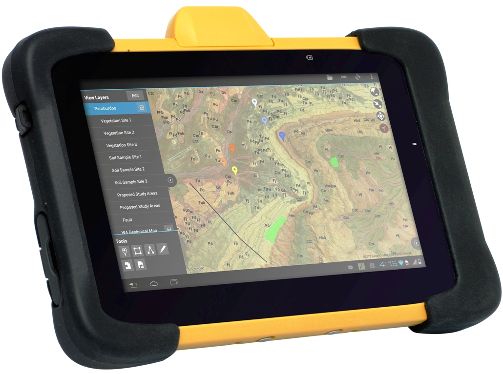
The DT391GS combines a 9-inch sunlight-readable, capacitive touch display with an energy-efficient Intel dual-core processor in a compact, durable package. With the high-accuracy GNSS module options (Hemisphere or Trimble), the foldable antenna, and Windows or Android operating system. The DT391GS also offers protection in demanding environments with IP65 and MIL-STD-810G ratings for dust and water, and shock and vibration resistance.
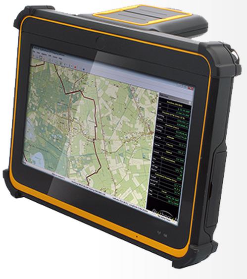
The DT395GS tablet.
The DT395GS offers a 9-inch sunlight-readable capacitive touch screen, an energy efficient Intel dual-core processor, and a choice of Windows or Android operating systems. The GNSS positioning module has u-blox GNSS module. The IP65 rating, and military-standard MILSTD-810G and MIL-STD-461F ratings, as well as wide temperature range, make the DT395GS reliable even in harsh, mission-critical environments.
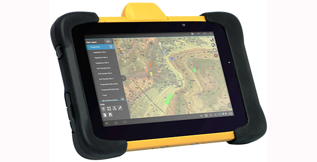
The DT307GS GNSS tablet features a brilliant 7-inch capacitive touch screen and a quad-core, energy efficient processor with a built-in, high-accuracy u-blox GNSS module. The size and weight of the DT307GS make this tablet portable for long-term handling in the field, DT Research said.
The DT307GS tablet
All of the DT Research Rugged GS Tablets offer hot-swappable batteries for continuous operation, enabling real-time project efficiency between staff in the field and in the office. With wireless support for Bluetooth, 802.11, WCDMA and HSPA+ connectivity and optional GSM networking, the tablets keep staff connected from any location.
The DT391GS and DT395GS have Trusted Processing Module (TPM) encryption for security support, and a choice of Microsoft Windows Embedded Standard 7 or 7 Professional, or Android operating system making these tablets flexible to integrate with existing applications.
An optional 5-megapixel camera offers another data capture tool to record visual information, and an optional 3G cellular data module provides data connectivity for navigation and real-time data transfer, DT Research said.
The DT391GS, DT395GS, and DT307GS are available now, form more information, contact DT Research at [email protected].
When subjected to very strong interference, a GNSS receiver can be totally blinded and stop working. This is often the scope of intentional jammers. However, in a number of cases the presence of interference is severe enough to significantly decrease receiver performance, but not so much as to make the receiver lose its lock on the satellite signals or blind the acquisition of the satellite signals.
Such intermediate power values turn out to be the most dangerous cases, because sometimes they cannot be detected, but lead to a worsening of the positioning performance. The accuracy of the position solution depends on, among others, the quality of the pseudorange measurements and/or the phase measurements. Thus, when radio-frequency interference (RFI) degrades the pseudorange and phase measurements or induces cycle slips on the phase measurements, the accuracy of the position solution will decrease.
Impact on the Front End
The front-end filters the incoming signal, demodulating it to the chosen intermediate frequency before performing the analog-to-digital conversion (ADC).We must consider the presence in the front end of the adjustable gain control (AGC) between the analog portion of the front end and the ADC. When the GNSS band is interference-free, AGC gain depends almost exclusively on thermal noise, since the received signal power is below that of the thermal noise floor. When in-band interference is present, the AGC will squeeze the incoming signal to match the maximum dynamics of the ADC, causing a reduction of the amplitude of the useful signal, which may be lost. This may typically happen in the presence of some kind of wide-band interference (WBI) spread over a bandwidth larger than the passband of the front-end filter.
With narrow-band (NBI) or continuous-wave interference (CWI), statistics of the digital signal at the ADC output are also affected. In this case the AGC can still compress the input signal to avoid a stronger saturation, but the following receiver stages will have to deal with a GNSS contribution quantized only on lower levels.
In the presence of stronger interference, even the other components of the front end (filters and amplifiers) may be led to work outside of their nominal regions, generating nonlinear effects or clipping phenomena (in which the signal amplitude exceeds the hardware’s capability to treat them). In both cases, spurious harmonics are generated and mixed with the useful signal in the front end itself.
Impact on the Acquisition Stage
If the interference is not driving the AGC/ADC to full saturation, the acquisition module is still able to perform its task, processing the interfered signal to estimate the code phase and the Doppler shift with respect to the local code. The correlation with the local code can be seen as a spreading operation followed by a filter.
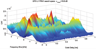
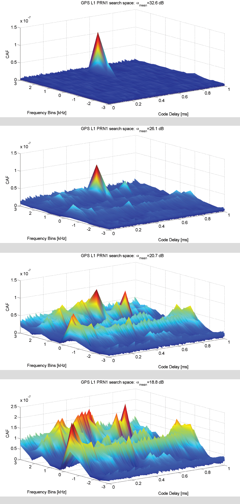
Figure 1. GPS L1 C/A acquisition search space in (a) an interference-free environment and in the presence of (b) –140 dBW in-band CWI; (c) –135 DBW in-band CWI; (d) –130 dBW in-band DWI.
Figure 1 showsthe acquisition search space for different levels of theinterfering power of a CWI from –140 to –130 dBW compared to the interference-free case. The search spaces depicted for the four scenarios are achieved using 1 ms of coherent integration time and three non-coherent accumulations, and the peak-to-noise-floor separation defined as
is considered as a figure of merit. The value of αmean decreases as the interfering power increases, thus increasing the probability of a false alarm. With the increasing power of the CWI, a modulation effect in the search space floor in the Doppler domain dimension can be observed. Such an effect is mainly determined by the new harmonics components generated by the multiplication between the locally generated carrier and received CWI. Such an effect also depends on how the interfering signal and the useful GNSS signal are combined at the entrance to the acquisition block, which in turn depends on the random variables φ0 and θint.
In the presence of WBI, a different effect is observed in the acquisition search space. Considering a band-limited Gaussian white noise spread all over the GNSS useful filtered signal components, the effect on the CAF envelop is an increase in the noise floor. This increases the search space noise floor. The presence of additive band-limited noise causes a uniform increase in the noise floor tin the search space that might mask the correct correlation peak and thus fool the acquisition process.
Impact on the Tracking Stage
Interference impact on the tracking stage has a direct consequence on the quality of the measured pseudorange. Harmful interfering signals increase the variance of the time-of-arrival (TOA) estimate by the discriminator and modify the shape of the S-curve of the code discriminator, thus creating in some cases a bias in the measurements.
Figure 2 depicts outputs of the early-prompt-late correlators. In the presence of in-band CWI and of NBI, the interference is injected 9.3 seconds after the beginning of the tracking stage where the receiver is correctly locked on the received signal. A CWI, shifted 200 kHz with respect to the signal intermediate frequency (in correspondence with a C/A code spectrum line), increases the noise at the correlators outputs and leads to harmonic behavior of the early-prompt-late correlator outputs.
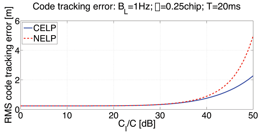
Figure 2. GPS L1 C/A code tracing error comparison: coherent and non-coherent early-late processing (CELP and NELP).
NBI increases the variance of the correlators’ outputs; this directly increases the pseudorange error and the noise on the receiver phase measurements. Additive band-limited noise leads to an overall increase in the carrier phase discriminator output variance over the 3σ threshold, which for a PLL two-quadrant arctangent discriminator is 45 degrees. When in presence of strong CWI, a sudden jump of the phase discriminator output is detected as soon as the CWI is injected onto the received signal.
Impact on the Estimated Signal-to-Noise Ratio
Sticking to the definition of C/N0 as the ratio between the received power and the power spectral density due to thermal noise at the input of the receiver, the presence of interference should not change the value, since the thermal noise is not increasing. However, the C/N0 value provided by the receivers is estimated on the basis of the correlator outputs at the tracking stage. For this reason the estimation is affected by the presence of the additional (nonthermal) noise generated by the interference. The variation of the C/N0 can also be used as observable for interference (or other threats) detection.
Chapters: The Interference Threat; Classification of Interfering Sources and Analysis of the Effects on GNSS Receivers; The Spoofing Menace; Analytical Assessment of Interference on GNSS Signals; Interference Detection Strategies; Classical Digital Signal Processing Countermeasures to Interference in GNSS; Interference Mitigation Based on Transformed Domain Techniques; Antispoofing Techniques for GNSS. The book is intended for members of the engineering/scientific community with pre-existing knowledge of satellite navigation principles and GNSS.
FabIo Dovis holds a Ph.D. in elecronics and communications engineering from Politecnico di Torino, Italy, where he is an associate professor.
Topcon Positioning Group has announced the latest edition of its 3D mobile mapping system. The IP-S3 is on display at the SPAR International 3D Measurement and Imaging Conference, held March 30-April 2 in Houston, Texas. The system employs the integration of an inertial measurement unit (IMU) and GNSS receiver with a vehicle’s onboard electronics to offer high-density mobile digital imaging.
“The IP-S3 is more compact, lightweight, and scans at a rate of up to five times faster than previous models,” said Charles Rihner, vice president of the Topcon GeoPositioning Group. “Weighing in at 39 lbs. (18 kg), it’s light enough that a single person could mount it on a car, truck or SUV without any assistance from anyone else.”
Scanning at 700,000 points-per-second, the rotating LiDAR sensor captures the 360-degree environment with 32 internal lasers. The IP-S3’s six-lens digital camera is designed to provide data-rich results with its 30 MP panoramic imagery.
The system pairs with Topcon Mobile Master Field and Office software suite to perform all post-processing functions in a single application.
“The software suite offers a complete all-in-one processing workflow, turning raw sensor data collected by the IP-S3 system into rich and precise point clouds and images,” Rihner said.
2015 GNSS Market Report: European GNSS Agency Provides a Fresh Look at Worldwide Growth
The fourth edition of the European GNSS Agency’s (GSA’s) GNSS Market Report provides a comprehensive source of knowledge on this dynamic global market. The report has become a key reference for organizations building their GNSS market strategies. The new edition provides:
Comprehensive updates on previous analyses;
New statistics of the GNSS receiver capabilities of the 31 top global manufacturers, offering in total more than 300 models;
Insights on the GNSS industry and regional shares of the GNSS market
A more granular segmentation of the global GNSS market, namely: European Union (EU28); North America (including the United States, Canada, Mexico); Asia-Pacific (including China, Japan, Australia, India, Republic of Korea); Non-EU28 Europe (Norway, Switzerland, Russia, Ukraine); Middle East and Africa (Turkey, Israel, South Africa, UAE, Saudi Arabia); South America and Caribbean (including Brazil, Argentina, Colombia, Guatemala)
Information on a new market segment: Timing and Synchronization
Plus additional applications within existing segments, such as recreational navigation, fishing vessels, personal locator beacons, emergency locator transmitters and digital tachograph.
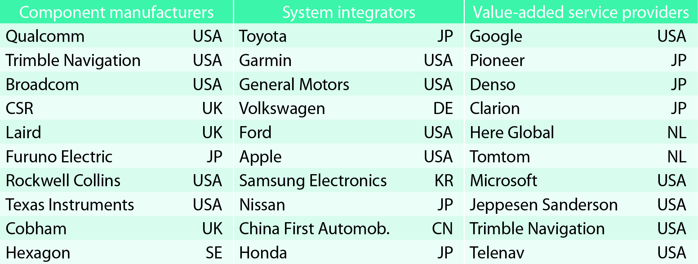
TABLE 1. Top 10 companies in each group based on 2012 revenue.
Key Findings
Top-line insights from the fourth GSA GNSS Market Report:
The global GNSS downstream market is forecast to increase by 8.3 percent annually from 2013– 2019, then slow down to 4.6 annually around 2023, growing on average faster (7 percent) than the forecast global GDP in this period (6.6 percent).
The installed base in the mature regions of EU28 and North America will grow steadily (8 percent per year) to 2023. The primary region of growth will be Asia-Pacific, which is forecast to grow 11 percent per year from 1.7 billion in 2014 to 4.2 billion devices in 2023 — more than the EU and North America together. The Middle East and Africa will grow at the fastest rate (19 percent per year), but starting from a lower base.
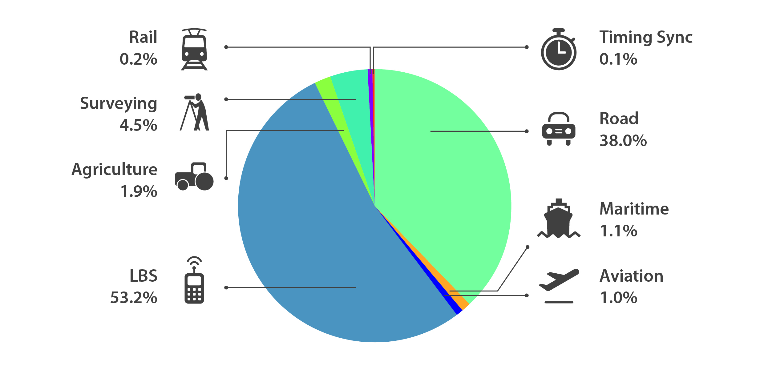
Location-Based Services (LBS) and Road dominate cumulative GNSS revenues, driven by booming sales of smartphones and in-vehicle devices, location-aware applications and data services.
With emerging economies catching up in terms of GNSS devices per capita, the Digital Divide will narrow, driven by the take-up of smartphones. The growing dominance of smartphones (3.08 billion in 2014) is foreseen as the most popular platform to access LBS.
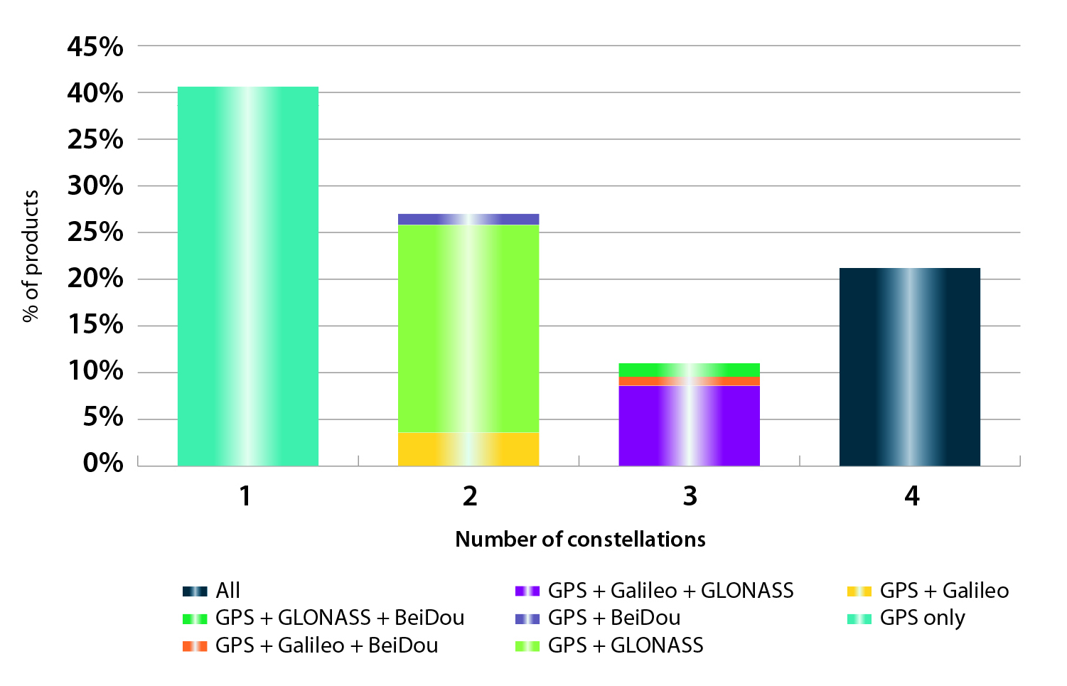
In the analysis of the capabilities of GNSS receivers and chipsets, it is reported that more than 60 percent of currently available receivers and chipsets support a minimum of two constellations with more than 20 percent supporting all four of them.
FIGURE 2. SUPPORTED CONSTELLATION BY RECEIVERS Chart shows the percentage of available receivers capable of tracking signals from one GNSS (such as GPS only), two GNSS (GPS + Galileo, GPS + GLONASS, GPS + BeiDou), three GNSS (GPS + Galileo + GLONASS, GPS + Galileo + BeiDou, GPS + GLONASS + BeiDou) or tracking signals from all constellations at the same time. The percentages add up to 100 percent. We can conclude that almost 60 percent of all available receivers, chipsets and modules are supporting a minimum of two constellations, showing that multi-constellation is becoming a standard feature across all market segments.
New Charts
The report includes new infographics presenting:
Global GNSS downstream market size, core and enabled (2013 to 2023)
GNSS industry share by region (2012)
The global shares of companies among components manufacturers, systems integrators and value-added service providers (2012)
Capability of GNSS receivers and chipsets, all segments (2015)
Supported constellation by receivers and chipsets , all segments (2015)
Detailed analysis of key GNSS segments: LBS, Road, Aviation, Rail, Maritime, Agriculture, Surveying, Timing and Synchronization, quantified in terms of:
Shipments of GNSS devices by application and region (2013 to 2023)
Installed base of GNSS devices by application and region (2013 to 2023)
Core revenues from GNSS device sales by application and region (2013 to 2023)
Capability of GNSS receivers and chipsets (2015)
Supported constellation by receivers and chipsets (2015).
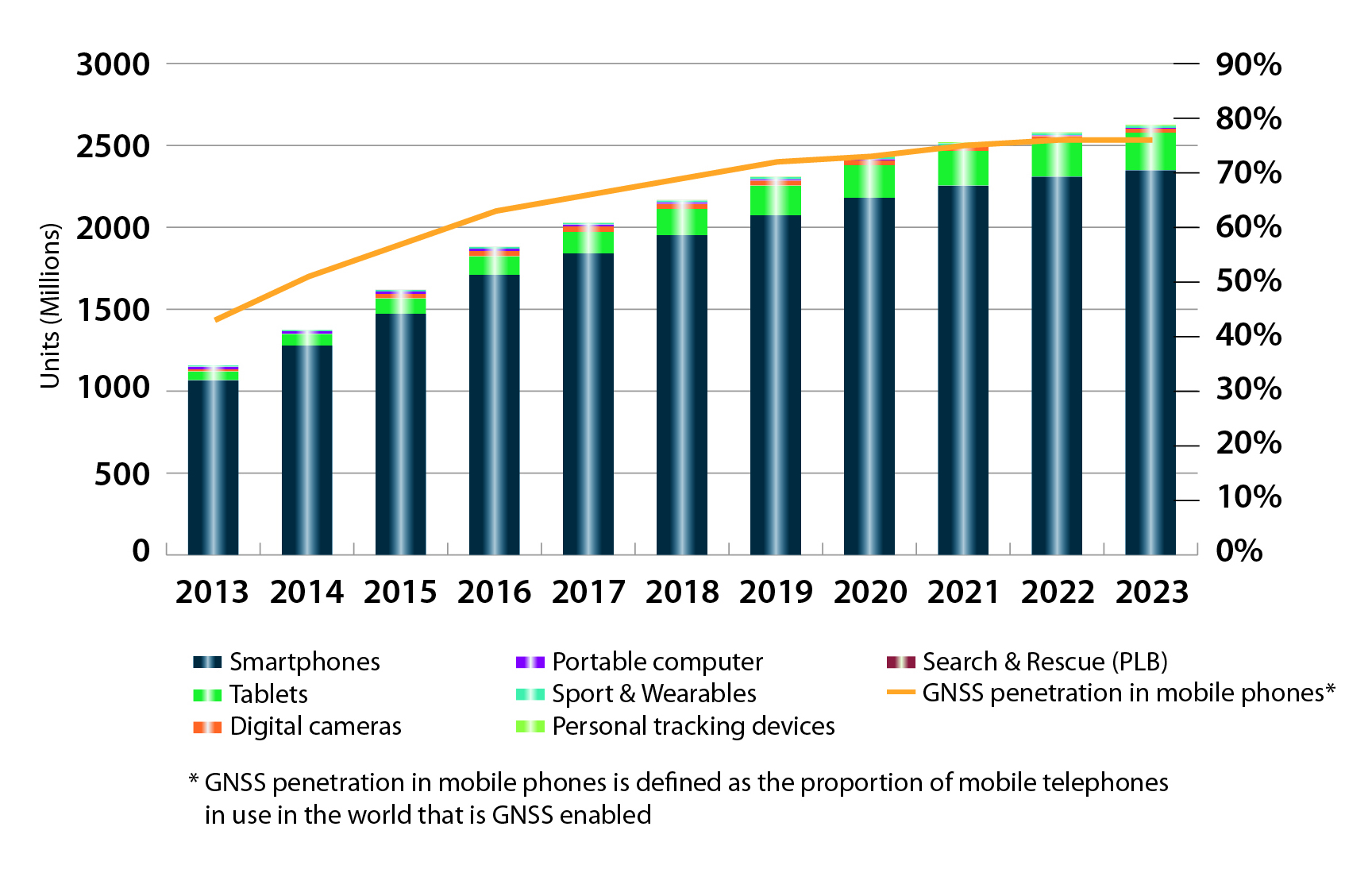
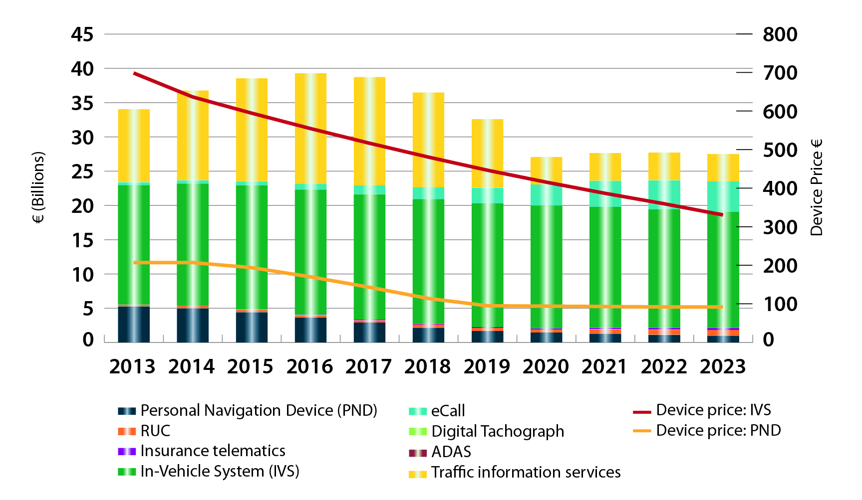
FIGURE 3. LOCATION-BASED SERVICES SECTOR GNSS shipments by type; GNSS penetration in mobile phones is defined as the proportion of mobile telephones in use in the world that is GNSS enabled.FIGURE 4. ROAD SECTOR Core revenue from GNSS device sales and services by application.
Methodology
The “GSA GNSS Market Report” is compiled by the GSA and the European Commission and was produced using the GSA’s systematic Marketing Monitoring and Forecasting Process.
The underlying market model uses advanced forecasting techniques applied to a wide range of input data, assumptions, and scenarios to forecast the size of the GNSS market in terms of shipments, revenue and installed base of receivers.
Historical values are anchored to actual data in order to ensure a high level of accuracy. Assumptions are provided by expert opinions and model results are cross-checked against the most recent market research reports from independent sources, before being validated through an iterative consultation process with sector experts and stakeholders.
GPS World will host a webinar this Thursday, March 19, on the merits of using simulated jamming, spoofing and interference scenarios to prepare GNSS receivers for the brave new world of coping with adverse signal effects. It’s clear that users need to still operate commercially and individually, even when they get hit by extraneous interference — intended or otherwise — in a world where cigarette-lighter jammers, engineering “lash-up” spoofers, and badly designed commercial gear can ruin a person’s day.
Recently, I had a conversation with Guy Buesnel, market segment manager, GNSS Vulnerabilities, at Spirent Communications. He wanted to alert me to the concept that jamming and spoofing is at a stage where Internet hacking was many years ago. Hacking has progressed from the typical loan student in his bedsit or studio apartment pounding on a keyboard to break down banking or other institutional firewalls, to nowadays, where focused groups mount hacking attacks on targeted agencies or companies lasting days, weeks, even months. Huge effort is currently being applied to defending against these and future focused attacks.
Buesnel’s point is that organized attacks on GNSS may be coming, and coming soon. Individuals and groups are already self-jamming to prevent detection — organized car and truck thieves wanting to avoid location of stolen assets, or truck drivers wanting to prevent their employers knowing their whereabouts — using easily obtained “personal cigarette lighter” or even professional-looking jammers (see figure below). Jamming GPS L3 at 1381.05MHz might awaken U.S. Department of Defense (DOD) interest as it’s used by the Nuclear Detonation (NUDET) Detection System Payload (NDS), and L4 at 1379.913 MHz is currently only used for studies on additional ionospheric corrections.
But Buesnel warns that organized spoofing could soon start to happen, and happen frequently. And it could be argued that spoofing is more dangerous than jamming, because a user or someone monitoring a user might not know for some time that their position information has been compromised. Long enough, perhaps, for an unwary user to get into potentially serious trouble, especially in a higher speed, fuel-restricted application like an aircraft or a small boat running some distance offshore.
GNSS is already embedded into the critical infrastructure of utility providers, and also telecoms, financial and transport sectors for timing/synchronization or positional data, and the growth in vehicle automation will soon see GNSS being used for even more safety-critical applications. The security of GNSS is already of huge importance and a “GNSS hacking attack,” like those experienced by Internet users, could achieve significant disruption across a host of operational segments. Precise GNSS timing is already essential for time stamping some transactions and used extensively for cell-site synchronization, so significant damage could occur if timing information were to be compromised.
While an intentional spoofing attack has yet to be confirmed — except under conditions such as that drone spoofing demonstration and then the White Rose luxury yacht spoofing trials, both by University of Texas/Cockrell School of Engineering graduate students — unintentional spoofing has indeed been reported. GNSS repeaters radiating at higher power levels than actual GNSS signals can be the source of such spurious signals. The result can be that GNSS receivers may acquire and track the higher power repeater signals, and the receiver position becomes that of the repeater. Use of GPS repeaters in unsuitable locations, such as for production tests in an open workshop, have been reported. The risk is that GNSS signals could extend outside the building and affect users, so GPS receivers could be spoofed and tricked into reporting an incorrect position.
White Rose 213-foot luxury yacht. Photo: Tony Murfin
For more than 20 years, the information security community has debated publishing the methods used by hackers and others to expose and attack vulnerabilities within products. Initially, things were kept hidden and were only shared between groups of hackers or IT administrators. However, online hacker forums quickly distributed knowledge — often including sample code. This allowed everyone from security researchers and IT administrators to hackers to learn about the vulnerabilities of applications and critical systems. It would seem that both researchers and hackers alike have broken the spell, and now it’s easy to spread the word about backdoors and weaknesses in firewalls, critical applications and the like.
Fast forward, and we are now in the age of mass-market access to jammers of all kinds through offshore websites — even if it’s illegal to operate such devices. However, it’s also illegal to hack the Department of Defense, but that has not prevented hackers in the past from assaulting and penetrating all sorts of secure DoD computing facilities. So, let’s just assume that the individuals who get a kick out of creating mayhem may eventually turn to something new — and the age of jamming and spoofing for fun may be upon us.
All is not lost, however. Just as applications for finding and killing viruses have become more robust, and new “antidotes” and warnings are now automatically downloaded to your PC even as they are created, and huge amounts of effort are now being applied to creating the most robust firewalls, so the designers of GNSS receivers are working hard to immunize their systems against anticipated attacks. And simulator/replay manufacturers such as Spirent Communications, IFEN, Spectracom and Racelogic are developing and fielding ready-made spoofing and jamming capabilities and scenarios with which manufacturers can test and qualify their receivers — which you may well hear about during the coming GPS World webinar on March 19.
Nevertheless, some people in the industry are urging members of the GNSS community to act more cooperatively and report spoofing and jamming incidents/attacks for their own good. It seems that the industry only collaborates in the face of a major common threat — take the ultra wideband and LightSquared episodes where the response was virtually unanimous. While most GNSS manufacturers in the meantime tend to maintain a very proprietary cover to their field experience and technological solutions, this still leaves customers exposed to product vulnerabilities. The GNSS community now has the advantage that the information security community has been working through these hurdles for the past two decades. Lessons learned include the following:
Controlled, responsible disclosure and cooperation allows everyone to monitor the threat and how it is being dealt with.
Without restricted disclosure and preventive solutions, attacks will always take advantage of weaknesses.
Eventually, disclosure of product vulnerabilities will result in more respect and confidence in manufacturers by users.
Rapid resolution of issues is essential.
The GNSS community has an opportunity to come together, learn from the information security community, and adopt best practices to secure and protect its customers.
(With grateful thanks to Guy Buesnel and David DeSanto of Spirent Communications!)
By Thorsten Lück, Günter Heinrichs, IFEN GmbH, and Achim Hornbostel, German Aerospace Center
This article discusses the GALANT adaptively steered antenna array and receiver and demonstrates the test scenarios generated with the GNSS simulator. Exemplary results of different static and dynamic test scenarios are presented, demonstrating the attitude determination capabilities as well as the interference detection and mitigation capabilities.
The vulnerability of GNSS to radio frequency interference and spoofing has become more and more of a concern for navigation applications requiring a high level of accuracy and reliability, for example, safety of life applications in aviation, railway, and maritime environments.In addition to pure power jamming with continuous wave (CW), noise or chirp signals, cases of intentional or unintentional spoofing with wrong GNSS signals have also been reported.
Hardware simulations with GNSS constellation signal generators enable the investigation of the impact of radio interference and spoofing on GNSS receivers in a systematic, parameterized and repeatable way. The behavior of different receivers and receiver algorithms for detection and mitigation can be analyzed in dependence on interference power, distance of spoofers, and other parameters. This article gives examples of realistic and advanced simulation scenarios, set up for simulation of several user antennas simultaneously.
The professional-grade high-end satellite navigation testing and R&D device used here is powerful, easy to use, and fully capable of multi-constellation / multi-frequency GNSS simulations for safety-of-life, spatial and professional applications. It provides all L-band frequencies for GPS, GLONASS, Galileo, BeiDou, QZSS, SBAS and beyond in one box simultaneously. It avoids the extra complexity and cost of using additional signal generators or intricate architectures involving several hardware boxes, and offers full control of scenario generation. A multi-RF capable version provides up to four independent RF outputs and a master RF output that combines the RF signal of each of the up to four individual RF outputs.
Each individual RF output is connected to one or more “Merlin” modules (the core signal generator module for one single carrier) allowing simulation of up to 12 satellites per module. Because of the flexible design of the Merlin module, each one can be configured to any of the supported L-band frequencies.
As one chassis supports up to nine individual Merlin modules, different Multi-RF combinations are feasible:
two RF outputs with up to four modules each
three RF outputs with up to three modules each
four RF outputs with up to two modules each.
With these configurations, the user can simulate different static or dynamic receivers or even one receiver with multiple antennas, covering such challenging scenarios as ground networks, formation flying or use of beam-forming antennas.
As the user is free to assign each individual module to a dedicated simulated antenna, the user could also employ up to nine modules to simulate nine different carrier signals for one single antenna using the master RF output, thus simulating the complete frequency spectrum for all current available GNSS systems in one single simulation.
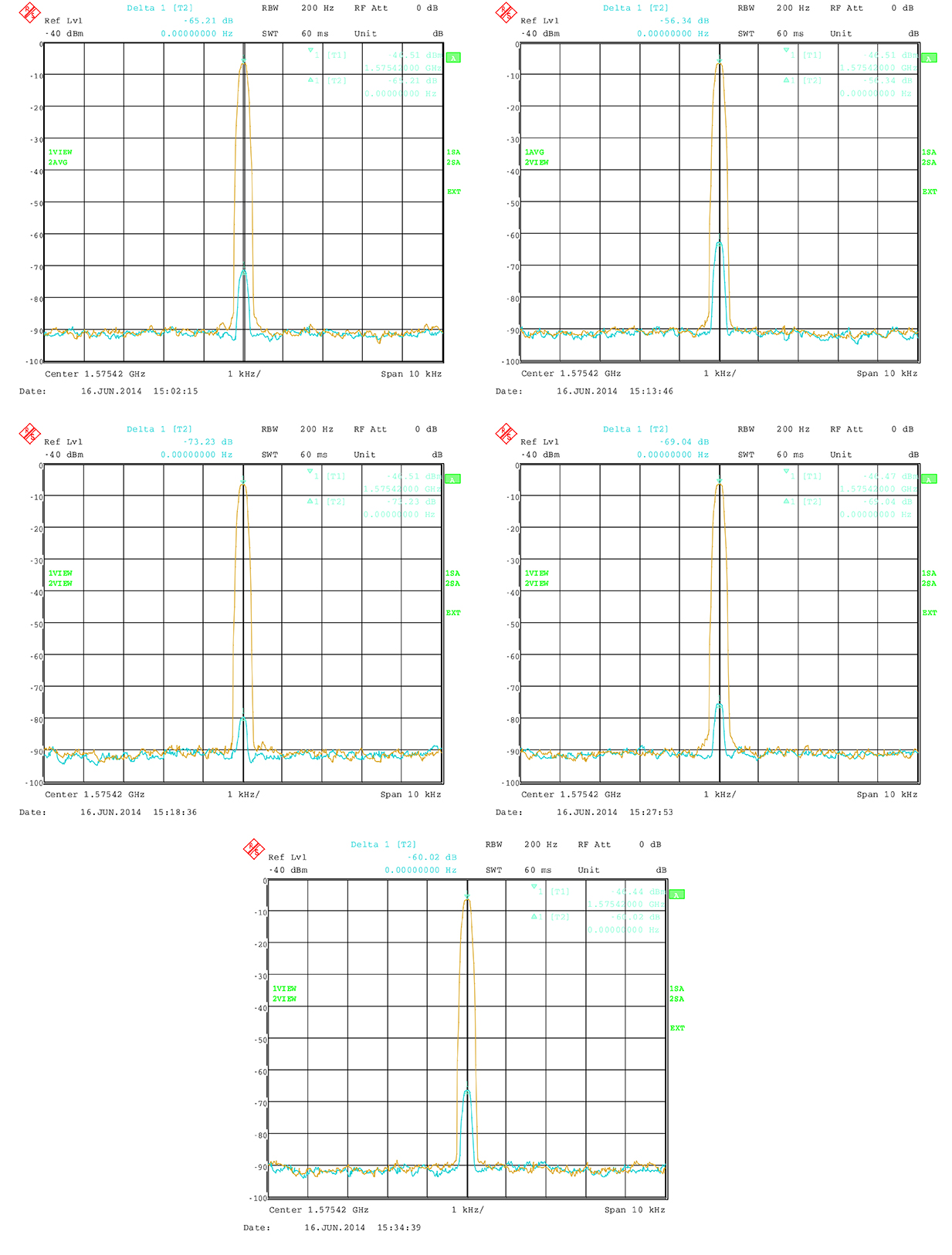
All modules are calibrated to garantee a carrier phase coherency of better than ±0.5°. Figure 1 shows the output at the RF master of two modules assigned to the same carrier but with a phase offset of 180°.
Figure 1. Carrier-phase alignment of the high-end simulator with six modules compared to the first module.
Theoretically, the resulting signal should be zero because of the destructive interference. In practice, a small residual signal remains because of component tolerance, small amplitude differences and other influences. Nevertheless the best cancellation can be seen at this point. The phase accuracy can now simply be estimated from the measured power level of the residual signal:
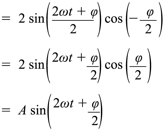
(1)
(2)
with
This means that the sum of two sine waves with the same frequency gives another sine wave. It has again the same frequency, but a phase offset and its amplitude is changed by the factor A. The factor A does affect the power level. If φ is 180° then A is 0, which means complete cancellation.
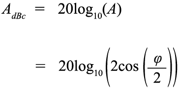
So A shows the power of the resulting signal relative to the single sine wave. It can also be transformed to dB:
(3)
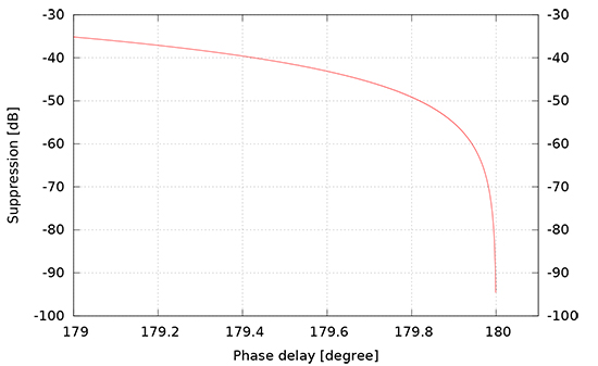
Figure 2 shows the carrier suppression as a function of carrier phase offset with a pole at 180ϒ.
Figure 2. Carrier suppresion as a function of phase delay.
The factory calibration aligns the modules to a maximum of 0.5ϒ misalignment. The measured suppresion therefore shall be better than 41.18 dBc. In practice, the residual signal is also caused by other influences, so that the actual phase alignment can be expected to be much better.
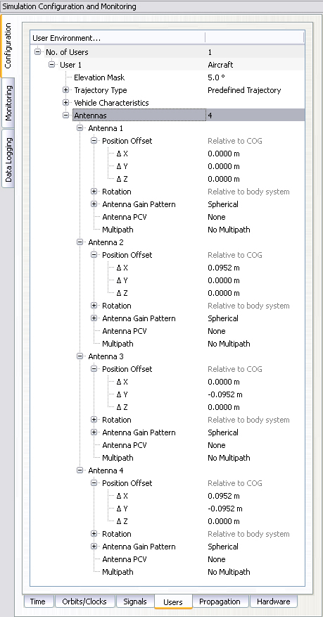
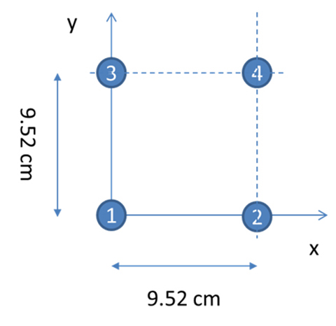
With four RF outputs, the received signal of a four element antenna can be configured very easily. Figure 3 shows the dialog to configure a four-element antenna with the geometry shown in Figure 4. Note that the antenna elements are configured in the body-fixed system with the x-axis to front and the y-axis to the right (inline with a north-east-down, NED, system when facing to north), while the geometry shown in Figure 4 follows an east-north-up (ENU) convention.
Figure 3. Configuration of individual antennas per receiver.Figure 4. Geometry of the GALANT four-element phased-array antenna (view from top).
The following sections give an overview of multi-antenna systems and discuss results from a measurement campaign of the German Aerospace Center (DLR) utilizing the simulator and the DLR GALileo ANTenna array (GALANT) four-element multi-antenna receiver.
Multi-Antenna Receivers
Multi-antenna receivers utilize an antenna array with a number of antenna elements. The signals of each antenna element are mixed down and converted from analog to digital for baseband processing. In the baseband, the signals received by the different antenna elements are multiplied with complex weighting factors and summed. The weighting factors are chosen in such a way that the received signals from each antenna element cancel out into the direction of the interferers (nulling) and additionally, for advanced digital beamforming, such that the gain is increased into the direction of the satellites by forming of individual beams to each satellite. Because all these methods work with carrier phases, it is important that in the simulation setup, the signals contain the correct carrier phases at the RF-outputs of the simulator corresponding to the user satellite and user-interferer geometry, and the position and attitude of the simulated array antenna.
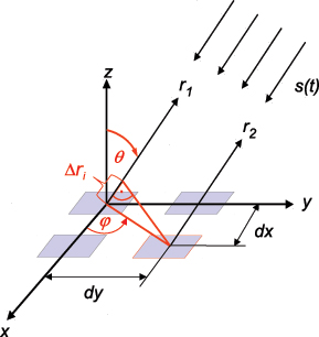
Figure 5 presents the geometry of a rectangular antenna array with 2×2 elements and a signal s(t) impinging from direction (ϕ, θ).
Figure 5. Parallel wavefront impinging on a rectangular array with 2×2 elements.
The spacings of the elements dx, dy are typically half a wavelength, but can also be less. The range difference for antenna element i relative to the reference element in the center of the coordinate system depends on the incident direction (ϕ, θ) and the position (m=0,1, n=0,1) of the element within the array:
(4)
The corresponding carrier phase shift is:
(5)
For CRPA and adaptive beam forming applications, the differential code delays may be neglected if they are small compared to the code chip length. However, it is essential that the carrier phase differences are precisely simulated, because they contain the information about the incident direction of the signal and are the basis for the array processing in the receiver. For instance, the receiver can estimate the directions of arrival of the incident signals from these carrier phase differences.
Now we consider a 2×2 array antenna. It can be simulated with the simulator with four RF outputs, where each output corresponds to one antenna element. In the simulator control software, a user with four antennas is set up, where the position of each antenna element is defined as an antenna position offset relative to the user position. In this approach, both differential code and carrier delays due to the simulated array geometry are taken into account, because the code and carrier pseudoranges are computed by the simulator for the position of each antenna element. However, the RF hardware channels of the receiver front-end may have differential delays against each other, which may even vary with time. If the direction of the satellites and interferers shall be estimated correctly by the receiver algorithms, a calibration signal is required to measure and compensate these differential hardware delays.
For the real antenna system, a binary phase-shift keying (BPSK) signal with zero delay for each antenna channel is generated by the array receiver and fed into the antenna calibration port. For the simulation, this calibration signal must also be generated by the constellation simulator.
In a simple way, a satellite in the zenith of the user antenna can be simulated, which has the same distance and delay to all antenna elements. Unfortunately, this simple solution includes some limitations to the simulated position and attitude of the user, because the user position must be at the Equator (if a “real” satellite is simulated in form of a geostationary satellite) and the antenna must not be tilted.
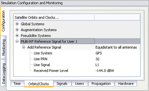
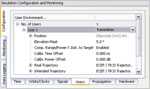
With a small customization of the simulator software, these limitations could be overcome. Figure 6 shows how to set up the generation of a reference signal. This reference signal can either be simulated as a transmitter directly above the user position, which follows the user position and thus allows also simulations offside the Equator, or simulated as a zero-range signal on all RF outputs, neglecting any geometry, which is the preferred method. The latter one is more or less identical to the reference/calibration signal generated by the receiver itself.
Figure 6. Configuration of a modulated reference signal.
The power level of this signal is held constant and is not affected by any propagation delay or attenuation simulated by the control center.
Attitude Determination
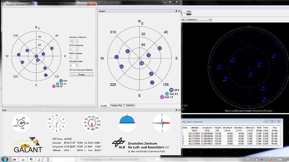
According to Figure 5, the phase difference measured between antenna elements is a function of the direction of arrival (DoA). Thus, the DoAs of the incident signals can be estimated from the phase differences. In the GALANT receiver, the DoAs are estimated by an EPSPRIT algorithm after correlation of the signals. Compared with the (known) positions of the GNSS satellites, this allows the estimation of the antenna array attitude. Figure 7 shows the sky-plot of simulated satellites as seen at receiver location (simulated on the right; reconstructed by the receiver from the decoded almanac in the middle and the DoA on the left). By comparison of the estimated DoAs of all satellites and the skyplot from the almanac, the attitude of the antenna is estimated (left). In addition, the attitude angles simulated by the simulator is given (right).
Figure 7. Simulating and estimating attitude with a multi-element antenna.
Simulation of Interference
It is possible to simulate some simple types of interference. Possible interference scenarios are:
Wideband Noise. By increasing the power of a single satellite of the same or another GNSS constellation, a wideband pseudo-noise signal can be generated. Using a geostationary satellite also enables simulating an interference source at low elevations and constant position. Use of power-level files also allow generation of scenarios with intermittent interference (switching on and off the interference) with switching rates up to 5 Hz.
CW or Multi-Carrier IF. By disabling the spreading code and navigation message, a CW signal can be generated. The simulator also allows configuration of subcarrier modulations. Without spreading code (or to be precise with a spreading code of constant zero) the generated signal will consist of two carriers symmetrically around the original signal carrier (for example, configuring a BOC(1,1) signal will create two CW signals at 1.57542 GHz ± 1.023 MHz, thus producing “ideal” interferer for the Galileo E1 OS signal.)
Depending on the number of Merlin modules per RF output, interference to signal ratios up to 80 dB could be realized, limited by a dynamic range of 40 dB within one module and additional 40 dB range between two modules. However, the maximum power level of one individual signal is currently limited to -90 dBm. If only one channel per module is used, the maximum power level of this single signal can be increased by another 18 dB (for example, by using one module solely for interference generation and another module for GNSS simulation).
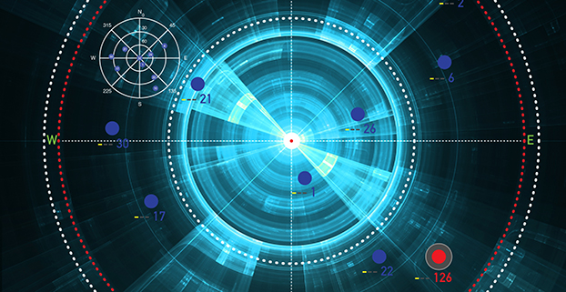
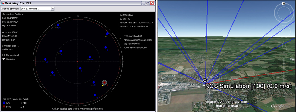
Figure 8 shows the simulated geometry for an interference scenario based on wideband noise generated by a geostationary satellite, producing –90 dBm signal power at the receiver front end. The interference source is very near to the direction of PRN 22 with a jammer power of –90 dBm, resulting in a jammer to signal ratio of J/S = 25 dB.
Figure 8. Geometry for the wideband noise interference scenario.
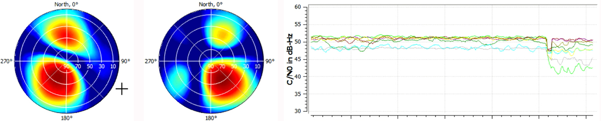
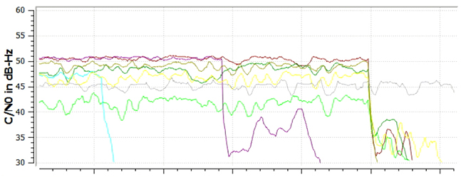
Figure 9 shows the two-dimensional antenna pattern as a result of the beam-forming before and after switching on the interferer. The mitigation algorithm tries to minimize gain into the direction of the interferer. As this also decreases gain into the direction of the intended satellite, the C/N0 drops by approximately 10 dB for PRN 22, because its main beam is shifted away from the interference direction. For satellites in other directions, the decrease in C/N0 is less: compare Figure9with Figure 10. However, the receiver still keeps tracking the satellite. After switching of beamforming, the signal is lost.
Figure 9. Beamforming for PRN 22 (light green line in lower plot) to mitigate for interference.Figure 10. Tracking is lost after switching off beamforming for individual channels (light blue, purple) and all channels (at the end of the plot).
Simulation of Spoofing
The simulation of a spoofing signal requires twice the resources as the real-world scenario, as every “real” LoS-signal must also be generated for the spoofing source. A simulation of an intentional spoofer who aims to spoof a dedicated position in this context is, however, very similiar to the simulation of a repeater ([un-]intentional interferer) device:
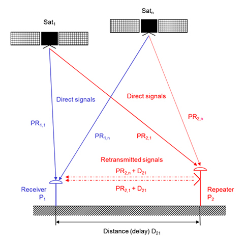
The repeater (re-)transmits the RF signal received at its receiver position. A receiver tracking this signal will generate the position of the repeater location but will observe an additional local clock error defined by the processing time within the repeater and the travel time between repeater and receiver position. A correct simulation for a multi-antenna receiver therefore has to superpose the code and carrier range as observed at the repeater location (considering geometric range between the transmit antenna of the repeater and the individual antenna elements) with the code and carrier ranges at the receiver location.
Instead of the location of the repeater P2, however, any intended location Px could be used to simulate an intelligent spoofer attack (Figure 11).
The simulator can generate such scenarios by configuring the position of the (re-)transmitting antenna and the intended position (for example, the position of the repeater). By calculating the difference between the real receiver position and the position of the transmitting antenna, the additional delay and free-space loss can be taken into account. The user may also configure the gain of the transmit antenna and the processing time within the repeater. Currently, this setup does only support one “user” antenna to be simulated. However, this feature combined with multi-antenna support will enable the simulator to simulate repeater or intelligent spoofer attacks in the future (Figure 12). To distinguish the “real” signal from the “repeated” signal, the “repeated” signal could be tagged as a multipath signal. This approach would allow simulation of the complete environment of “real” and “repeated” GNSS signals in one single simulator.
Figure 11. Geometry of repeater/spoofer and GNSS receiver.Figure 12. Simulator’s capability to simulate a repeater.
Manufacturers
The simulator producing the results described here is the NavX-NCS from IFEN GmbH. The simulator is valuable laboratory equipment for testing not only standard or high-end single-antenna GNSS receivers, but also offers additional benefit for multi-antenna GNSS receivers like the DLR GALANT controlled reception pattern antenna system.
The GNSS constellation simulator offers up to four phase-coherent RF outputs, allowing the simulation of four antenna elements with two carrier frequencies, each utilizing one single chassis being 19 inch wide and 2 HU high.
Simulation of intentional and unintentional interference is a possible feature of the simulator and allows receiver designers and algorithm developers to test and enhance their applications in the presence of interference to identify, locate and mitigate for interference sources.
Thorsten Lück studied electrical engineering at the universities in Stuttgart and Bochum. He received a Ph.D. (Dr.- Ing.) from the University of the Federal Armed Forces in Munich in 2007 on INS/GNSS integration for rail applications. Since 2003, he has worked for IFEN GmbH, where he started as head of R&D embedded systems in the receiver technology division. In 2012 he changed from receiver development to simulator technologies as product manager of IFEN’s professional GNSS simulator series NavX-NCS and head of the navigation products department.
Günter Heinrichs is the head of the Customer Applications Department and business development at IFEN GmbH, Poing, Germany.He received a Dipl.-Ing. degree in communications engineering in 1988, a Dipl.- Ing. degree in data processing engineering and a Dr.-Ing. degree in electrical engineering in 1991 and 1995, respectively. In 1996 he joined the satellite navigation department of MAN Technologie AG in Augsburg, Germany, where he was responsible for system architectures and design, digital signals, and data processing of satellite navigation receiver systems. From 1999 to April 2002 he served as head and R&D manager of MAN Technologie’s satellite navigation department.
Achim Hornbostel joined the German Aerospace Center (DLR) in 1989 after he received his engineer diploma in electrical engineering from the University of Hannover in the same year. Since 2000, he has been a staff member of the Institute of Communications and Navigation at DLR. He was involved in several projects for remote sensing, satellite communications and satellite navigation.In 1995 he received his Ph.D. in electrical engineering from the University of Hannover.His main activities are in receiver development, interference mitigation and signal propagation.
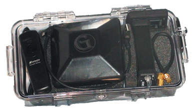
Geomatics USA from Gainesville, Fla., has designed a precision surveying and mapping system that can be easily stowed in an overhead compartment for airline travel. Surveyors can fit everything needed for important mapping and surveying jobs into a baseball-style bag, including tripods. The compact, light-weight system offers differential sub-foot accuracy.
Components easily pack into a baseball-style case.
The G1-m1 receiver system has many advantages over conventional GNSS receivers, Geomatics said. The system is designed for precision surveying jobs that require travel to remote areas of the world, and for traveling to job sites by commercial airline. The complete base and rover kit, including the tripods, rods, and batteries, fits into a single baseball style bag and weigh less than 10 kg, making it easy to stow as carry-on luggage.
The Geomatics USA G1 system is scalable from a simple single-frequency semi-mobile receiver — ideal for control networks and some semi-kinematic mapping applications — to a dual-frequency network RTK solution. All of the Geomatics USA G1 solutions perform precision-quality tasks at a fraction of the cost of major-brand equipment.
The G1-m1 system comes with a free processing software license for the first 50 systems that supports carrier-phase relative positioning and CA-code differential correction. The software is designed with a simple user interface for easy selection of base and rover data or automatic data download of the closest Continuously Operating Reference Station (CORS) from the U.S. National Geodetic Survey database. It is compatible with other RINEX based post-process systems around the world.
Complete survey set including GNSS receiver, antenna, battery and cables, fits in a small handheld plastic case.
According to Geomatics USA Chief Technology Officer Ahmed Mohamed, “The G1 product line fills the gap between survey applications, where cm-level precision is an absolute necessity, and mapping applications, where meter-level precision is acceptable. In fact, the G1-m1 product offers sub-foot precision in most cases and cm-level precision in ideal situations. Geomatics USA uses readily available components and open-source code to develop its end user product solutions. The objective is to make sure the software performs correctly with a very short learning curve for the user.”
For a limited time, Geomatics is offering a specially priced configuration for the first 50 systems through NavtechGPS, its worldwide distributor.
InvenSense Inc. is making available its InvenSense Positioning Library (IPL) software, designed to provide sensor-assisted positioning in places where GNSS alone cannot provide desired accuracy. Invensense is a provider of intelligent sensor system on chip for motion and sound in consumer electronic devices.
InvenSense made the announcement at Mobile World Congress, taking place in Barcelona, Spain March 2-5.
The IPL incorporates advancements in sensor-assisted positioning algorithms that allow use of inertial sensors to improve GNSS positioning in urban areas where satellite signals are either blocked or distorted by multipath, enabling continuous location availability while driving in underground parking lots, tunnels, or walking in urban canyons. The IPL enables continuous and accurate position, velocity and orientation in challenging operating environments.
These sensor-assisted positioning algorithms have been designed to operate under normal pedestrian and driving use without restrictions on the device orientation. Supported pedestrian use includes handheld, hand swinging, in pocket, call mode and belt holster. The algorithms also allow any use within the vehicle, such as in cradle, cup holder or simply left on a seat. The software was designed in a way to maximize accuracy and minimize constraints on the user.
The IPL is designed to operate with an IMU and GNSS receiver as minimum hardware. Integration with a magnetometer, barometer, and vehicle speed sensor is also available, which provides additional heading integrity as well as height and velocity accuracy for sensor-assisted positioning.
IPL is designed for smartphones using Android, iOS, Windows and general Linux operating systems and has already started shipping commercially. The underlying navigation technology comes from years of development at Trusted Positioning Inc., which was acquired by InvenSense this past summer.
“With more consumers using their smartphones for turn-by-turn navigation on foot or in vehicle, one of the most frustrating user experience issues is losing your GPS (GNSS) signal in an unfamiliar location or being re-routed erroneously due to multipath errors,” said Ali Foughi, vice president of Marketing and Business Development at InvenSense. “With IPL technology, high-accuracy location guidance is always available and provides smartphone OEMs with a differentiated user experience and consumers with a more reliable navigation solution.”
The InvenSense Positioning Library is available immediately.
InvenSense is exhibiting in booth #D61 in Hall 7 at Mobile World Congress.
Components easily pack into a baseball-style case. Photo: Nicholas DiGruttolo
By Nicholas DiGruttolo
When asked to do a small survey job overseas, we were concerned about shipping bulky and expensive survey equipment. Shipping costs are not trivial. Add to that the real possibility that your survey equipment may be confiscated by the local authorities, as ours was in Djibouti, and the cost of shipping equipment becomes a substantial part of the overall job. There should be alternatives, especially if accuracy requirements are not stringent.
Faced with this problem for a second time, we considered a new receiver system that has many advantages over conventional survey-grade GNSS receivers: It is small, lightweight and low-cost without sacrificing performance, making it ideal for precision surveying in remote areas of the world and for traveling to the job site by commercial airline. All the components, including the tripods, rods and batteries, are constructed from commercial off-the-shelf (COTS) components. A complete base and rover kit fits in a baseball bag and weighs less than 10 kilograms. The kit is sized and approved as carry-on luggage.
The system is scalable from a simple single-frequency semi-mobile receiver for control networks and some semi-kinematic mapping applications, to a dual-frequency network RTK solution.
The system comes with free processing software that supports carrier-phase relative positioning in real time and post mission, as well as precise-point positioning (PPP) and CA-code differential correction. The software is designed with a simple user interface for easy selection of base and rover data or automatic data download of the closest Continuously Operating Reference Station (CORS) from the U.S. National Geodetic Survey database.
Complete survey set including GNSS receiver, antenna, battery and cables, fits in a small handheld plastic case. Photo: Nicholas DiGruttolo
The system fills a gap between survey applications, where centimeter-level precision is an absolute necessity, and mapping applications, where meter-level is tolerable. The product offers sub-foot precision in most cases and centimeter precision in ideal situations.
Our team recently performed topographic mapping of an oil refinery site in Saudi Arabia and surveyed a precise-elevation network in Sarasota, Fla., to research the effects of sea-level rise. The small size of the COTS components simplified transport to Saudi Arabia, eliminating additional airline baggage fees and easing import through customs. Researchers performing the sea-level study reduced field time by increasing the number of receivers needed to observe a robust vertical control network.
Oil Refinery. The oil refinery project entailed mounting a GNSS antenna on the roof of an off-road vehicle and driving multiple transects around the 18-kilometer perimeter of the site to record the elevation of the terrain. Kinematic data was recorded at 1 Hz using a GPS-only version of the single-frequency receiver. Baseline length to the local reference station varied from less than 1 kilometer to about 10 kilometers. The site was open desert with no overhead obstructions or sources of multipath other than the roof of the vehicle on which the antenna was mounted. Post-processing and comparison to simultaneously collected data from a high-precision survey-grade receiver revealed positional accuracy of about 5 centimeters horizontal and 10 centimeters vertical, when the system’s trajectory was compared to the truth trajectory provided by the survey-grade receiver. Figure 1 shows the difference between the two trajectories. The system’s antenna was 2 feet away from the survey-grade antenna along the driving direction of the vehicle; the trajectory was mostly in the north-south direction and hence the 0.6-m offset in the plot!
Figure 1. Antenna location difference in the sub-decimeter range between the survey-grade system and the compact low-cost system. Note: A 0.6-m offset is to be removed from the difference, as the two antennas were mounted 0.6 m apart in the vehicle driving direction.
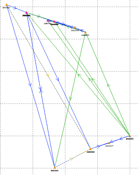
Sea Level. The sea-level-rise study required a high-accuracy vertical control network to cover a 2,500 hectare area. The purpose of the network is to determine the shortest term effects of sea-level rise with a rate of 1.8 millimeter/year in the affected area. Ten benchmarks were established throughout the area of interest, and a robust network of static observations was performed with a combination of two dual-frequency and two single-frequency receivers. The single-frequency receivers were GPS-only units where two standard 4-inch patch antennas were mounted on rods adjusted to a 0.9-meter height. The addition of two receivers provided greater redundancy and a stronger network solution in much less time than would have been possible with only one pair of survey-grade receivers. Figure 2 shows the addition of several loop ties to the network as a result of adding the two roving, lightweight receivers.
Figure 2. Sea-level rise monitoring network showing increased tie points and redundancy as a result of adding the extra lightweight precision receivers to the survey-grade receivers.
Nicholas DiGruttolo works as a field surveying manager for JBrown Professional Group Inc., Northrop Grumman Corporation, and has recently become vice president of surveying.
Microsemi Corporation is offering a new Integrated GNSS Master (IGM) solution for small-cell synchronization. The IGM is the company’s first solution that fully integrates a 1588v2 PTP grandmaster with a GNSS receiver and antenna in a small, fully contained package, designed to mount indoors.
The Microsemi IGM solves the challenge of indoor synchronization, which has been a significant hurdle for cost-effective small cell indoor deployments.
According to the Small Cell Forum, 80 percent of small cell needs are for indoor use. Microsemi expects the company’s new IGM to revolutionize indoor small cell deployments by eliminating the need for an antenna on the rooftop along with expensive power, cabling and installation costs associated with connecting the GNSS antenna to the 1588 grandmaster in a typical small-cell deployment.
IGR reports that the cost to deploy a small cell is approximately $31,000 on average and much higher than the cost of the small cell itself. Similarly, the cost of deploying a GPS antenna on a roof is typically $15,000 to $25,000 and can go up to $60,000 in high-rise buildings, in addition to the roof rental expense on a yearly basis.
The Microsemi IGM eliminates the need for an outdoor antenna and therefore significantly reduces the purchase, installation and maintenance deployment costs for typical GNSS antenna systems. The sensitive GNSS receiver and patented Microsemi timing algorithms result in an indoor GNSS timing solution that can be deployed in many different indoor environments.
The IGM uses Power-over-Ethernet (PoE) to simplify installation by utilizing standard Ethernet within a facility and requires no more than 12.95 watts of power directly from the Ethernet cable. The IGM is mounted on the wall or ceiling, connected to the network via PoE, and the unit will automatically self-configure, lock to GNSS signals and provide precise frequency and phase with its 1588v2 PTP grandmaster needed for small cell operation.
“The IGM product introduction is a continued commitment from Microsemi to address market and customer challenges in timing and synchronization,” said Eric Colard, director of marketing and business development for Microsemi’s Frequency & Time Division. “The IGM solution complements our flagship timing products and will work with them in tandem to provide a truly end-to-end timing and synchronization solution.”
“Deploying small cells indoor to provide better coverage and enhance capacity is becoming a priority for operators,” said Richard Webb, Analyst, Mobile Backhaul, at Infonetics, recently acquired by IHS. “The challenge of tight synchronization requirements for LTE has been difficult to solve; Microsemi’s IGM innovative solution enables mobile operators to precisely synchronize small cells indoor and lower deployment costs.”
“The time is right for such an innovative and disruptive solution as IGM from Microsemi,” said Earl Lum, president, EJL Wireless Research. “Since Small Cells for indoor are now being readily deployed, Microsemi solves a critical cost issue and technical challenge operators are facing. The compact form factor, plug and play capability, and scalable client support of the IGM product hits the sweet spot for indoor small cell projects.”
Editor’s Note: Tony Murfin is managing consultant for GNSS Aerospace LLC and editor of GPS World’s monthly Professional OEM newsletter. The views expressed are his own.
Another year has gone by, with another year of further improvements in navigation performance of micro-electro-mechnical systems (MEMS) inertial products. SBG Systems in France is now fielding a new generation of MEMS inertial products for much higher accuracy applications.
SBG Systems is based in Rueil-Malmaison, less than eight miles west of the center of Paris. Founded in 2007, SBG has developed a number of innovative MEMS inertial products over the last seven years, along with a respected reputation in the navigation industry, and by 2014 the company was recognized as the 26th fastest growing company in France.
The roots of the company began to form at the end of 2004, when a group of ECE School of Engineering students in Paris put a team together for a new UAV competition. The goal was to build a UAV of less than 1 kg, capable of flying autonomously indoors — at the time, a significant technical challenge. In 2004, miniature INS was not commercially available, so the team decided to build one, as well as other electronic parts such as the autopilot. The competition ran out of money, but the design was a success and led to a working UAV. The INS was by far the most advanced part of the project.
The students went back to their studies and took internships at UAV companies and ONERA (French aeronautics, space and defense research labs), but they still believed in the need for low-cost navigation solutions for the emerging civilian UAV market.
So, in 2007, three of the students — Raphaël Siryani, Thibault Bonnevie and Alexis Guinamard, S, B and G — formed SBG Systems with the goal of providing affordable, highly accurate MEMS inertial navigation systems for UAVs.
SBG quickly received its first Innovation Award from the French Research Ministry, and with this funding launched the IG-500 series of MEMS AHRS and INS in December 2008.
The company has since grown into a worldwide player with a strong product innovation focus. UAVs are still an important part of revenue, but the company has diversified into:
Aerospace and defense applications (UAVs, gimbaled cameras, antenna tracking, etc.)
Marine and offshore activities (ROV/AUVs, buoys, etc.)
Survey (hydrography, mobile mapping, aerial LiDAR, etc.)
SBG Systems has a small staff of mostly development and sales engineers — graduate students and experts. SBG has recruited navigation experts and some sales people from key players in the inertial business. Most (95%) have at least a master’s degree in engineering — R&D has 45% of the staff, and 40% are in sales, marketing and technical support. Production has been extremely automated and requires very few staff for in-house system assembly, calibration and final acceptance test. They do expect to double in size over the next two to three years.
The company is owned by the three founders, who still lead operations. SBG grew 1,304% over the last five years, and last year was ranked the 26th fastest growing company in France on the Deloitte Fast50. Today, SBG Systems has fielded more than 4,000 attitude and heading reference systems (AHRS) and INS (mostly INS), with almost a third of those delivered last year. The company forecasts growth for the next five years to be at this same phenomenal rate! SBG Systems currently offers a line of MEMS inertial sensors that include AHRS, inertial measurement units (IMU), and INS with embedded GPS (INS/GPS).
Ellipse-D dual-antenna mini INS/GNSS.
Not only have MEMS sensors improved in performance, but SBG has also developed advanced calibration capabilities that allow it to reach high-precision performance approaching high-end ring laser gyro accuracies in much smaller, less expensive packages. SBG owns an extensive set of temperature chambers combined with rotary tables and vibrating tables. Each SBG system gets to stay two to five days inside these calibration tools. But the “secret sauce” is in a state-of-the-art SBG developed calibration algorithm…
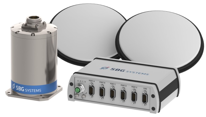
SBG buys MEMS gyros and accelerometers from MEMS manufacturers such as Colibrys, Analogue Devices and Silicon Sensing and builds complete inertial systems. The team embeds different GNSS receivers, depending on the product line and intended application — from miniature automotive-grade chipsets from u-blox to the very best from the key survey-grade players such as Septentrio, NovAtel and Trimble. Some customers may already have their own GNSS receiver, so SBG has developed and tuned their systems to work with any of these big manufacturers. The antenna employed depends on the receiver being used — from Tallysman Wireless and Antcom to Trimble, Septentrio or NovAtel — a very diversified range of antennas.
Ellipse-E.
SBG announced the Ellipse-D dual-antenna mini INS/GNSS earlier this month. The Ellipse-D is a miniature INS with an embedded dual-antenna survey-grade GNSS receiver for high-accuracy orientation and positioning.
Independent hydrographic testing in October 2014 of earlier model designs has already shown accuracy improvements, and the latest D version promises even better performance. The products tested were:
Ekinox-D
Ellipse-E, miniature inertial navigation system connected to a Hemisphere VS330 GNSS with two antennas.
Ekinox-D, inertial navigation system integrating a dual-frequency GNSS receiver with two antennas.
The test was a typical marine survey, with each leg about 550 meters long. Attitude performance was compared to a fiber-optic gyro compass reference system with much higher roll and pitch accuracy than the two SBG products under test.
Ellipse-E roll and pitch accuracy is better than the specs. The use of an RTK GNSS receiver additionally improves the sensor’s performance. The Ekinox-D also has good results — around 0.03° in both roll and pitch. SBG claims that low-noise gyroscopes and advanced algorithms are the basis for this performance.
The SBG list of 250 customers in 30 countries includes some impressive names, many outside Europe, and the company claims to have nearly 4,000 inertial sensors in the field. So this is not a prototype shop, but more a fully equipped production facility. SBG has opened an office in Chicago to address the North American market.
So, what are people doing with these devices? There are a number of applications in aerospace, land, marine and sub-sea.
In the aerospace industry, SBG sensors are used for UAV navigation and flight analysis — they could eventually be incorporated in certified avionics. They are also used for antenna tracking, camera stabilization and more demanding applications such as LiDAR orientation and data georeferencing.
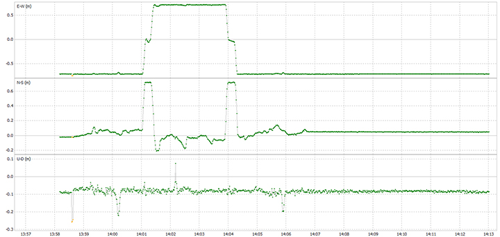
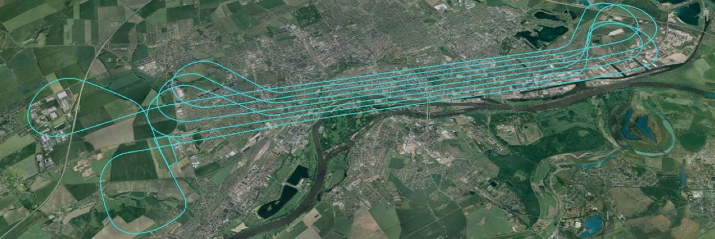
An Ekinox-N INS with embedded GNSS receiver was installed for the tests in a single-engine general aviation aircraft flying out of Magdeburg, Germany. A typical airborne survey-type flight was flown under mixed weather conditions with some turbulence, and roll, pitch, and altitude data was collected for real-time analysis and was also post-processed. A high-grade FOG-based AHRS was used as reference unit — with very high accuracy gyroscopes.
The flight pattern was typical of survey applications, with parallel straight lines of about 8.5 km. Altitude was 600 m and cruise speed was about 200 km/h.
Roll
Pitch
RMS Error Real Time (max)
0.043° (0.16)
0.043° (0.16)
RMS Error Post Processing (max)
0.017° (0.19)
0.025° (0.20)
Real-time accuracy remained below 0.05° RMS for roll and pitch. Post-processed output had a lower RMS error and a better stability over the whole flight. Only one GPS antenna was used in this test with Ekinox-N; nevertheless, heading reached an estimated accuracy of 0.06° when post-processed. The Ekinox-D model provides more accurate heading thanks to its integrated dual-antenna and GNSS receiver.
The Ekinox-N has been integrated on a UAV by Headwall in the U.S. for remote-sensing applications.
Headwall is a leading designer and manufacturer of high-performance hyperspectral imaging sensors for harsh environments. As a pioneer for remote-sensing applications, Headwall is the first to market a fully integrated remote-sensing solution combining hyperspectral and LiDAR sensors on a small UAV. This “total solution” approach has been welcomed by the remote-sensing market because it quickens time to deployment, decreases implementation costs, and enables operations in harsh environments.
The multi-rotor UAV carries Headwall’s lightweight Micro-Hyperspec VNIR hyperspectral sensor and a Velodyne LiDAR unit. The LiDAR collects a point cloud that reflects the field’s topographic relief, and the hyperspectral sensor delivers a picture showing spectral signatures of every object within the field of view. The SBG inertial navigation system has an embedded GPS and is used to provide positioning and orientation data. Weight is a key factor — Ekinox-N weighs only 500 grams, even though it integrates a survey-grade L1/L2 GNSS sensor to provide accurate positioning and precision roll, pitch, and heading data.
Mounted on the UAV, the Ekinox-N provides LiDAR and the hyperspectral camera with orientation and position during the whole flight. This and other data is recorded in real time at 200 Hz within the onboard computer. On the ground, the Headwall post-processing Hyperspec software fuses all sensor information. Ekinox-N data allows every scanned point and every pixel to be georeferenced and be tilt compensated to within a centimeter.
SLAM-based Indoor Mapping System by VIAmetris.
For miniature inertial sensors, smaller and lighter applications are possible at less cost. One of these applications includes the SLAM-based Indoor Mapping System by VIAmetris.
Simultaneous localization and mapping (SLAM) is becoming increasingly important to enable efficient indoor mapping. VIAmetris has created a different spin on indoor mapping with the “MID” portable SLAM-based scanner. This handheld system integrates a 2D LiDAR, a camera, an SBG Ellipse-A AHRS, and a tablet PC that shows the map being drawn while the user walks around inside the building. The AHRS also compensates for movement while orienting the generated maps to the north.
While the user walks, the 2D LiDAR scans in a horizontal plane by measuring 43,000 points per second across a 270° field of view. The SLAM technology progressively builds the map in the shape of lines made of points. At the office, the surveyor imports the data into the post-processing software and uses the lines of points to design the map. If there is any doubt about a specific shape — whether it is actually wall or furniture, for example — a photo of the location is available as MID automatically takes contextual pictures every meter, or whenever there is a change of direction, or manually.
The centimeter-level accurate map is then ready to be imported into most CAD software. As the system works without GPS, the generated map is not georeferenced or in a local coordinate reference system. To do so, the user links MID’s points cloud to a known point and all data is automatically referenced. MID is much easier to use than a laser distance meter, a tachometer, or a 3D scanner, and significantly reduces the time required for indoor mapping.
SBG is now working more often in the marine industry, equipping boat, cranes, or instrumented buoys. The company has even developed a specific solution for the hydrographic market. The SBG Ekinox Hydrography Solution integrates Ekinox-U which operates to a depth of 200 meters, and incorporates a SplitBox with a built-in tri-band RTK GNSS receiver and uses Terrastar, OmniSTAR, or Marinestar corrections.
The SBG Ekinox Hydrography Solution.
For subsea operations, positioning is required for ROVs and AUVs that navigate for minutes or sometimes for hours underwater. GPS fixes are only available when the vehicle comes close to the surface. But operators usually try to expend the time they are able to operate close to the seabed. To avoid typical INS drift, different aiding sources are used — the three main ones are acoustic positioning, Doppler velocity loggers (DVLs) and depth sensors.
Acoustic position is far more noisy and unstable than GPS.
DVL is a kind of 2D odometer, providing speed over the seabed.
The INS and the Kalman filter therefore play a key role to provide reference heading and reliable position data.
It’s a major concern when you have a massive ROV working on pipes under an offshore platform. Any mistake can cause severe damage and cost millions.
So SBG is moving along and taking on new, challenging applications with a range of MEMS inertial products that appear to be growing quite rapidly, with ever-improving performance. Once upon a time, we couldn’t stay anywhere within RTK-level performance during GPS outages because of the high drift-rate of MEMS inertial devices. Now, SBG has introduced its latest Ellipse-D dual-antenna mini INS/GNSS spec’ed at 0.1° real time for pitch and roll, with 2-cm RTK position.
The Apogee INS/GNSS.
And just today, SBG Systems has even bigger news with the release of the Apogee series, which is Apogee’s most accurate, robust and cost-effective MEMS technology inertial navigation system. The Apogee INS/GNSS integrates the very latest generation of MEMS sensors along with a triple-frequency GNSS receiver, achieving 0.008° in roll and pitch in real time, and 0.005° in post-processing. With two antennas, it also provides reliable and accurate heading.
Amazing what scientific skill, focused investment and time has done for MEMS inertial technology!
GPS World, the leading publication serving the GNSS Industry, is pleased to announce the industry’s first online buyers guide — gpsworldbuyersguide.com — featuring access to information on hundreds of manufacturers, products and services.
“We’ve taken the GPS World Buyers Guide in print, which we’ve been publishing for 20+ years, to an entirely new level,” said Alan Cameron, editorial director and group publisher of GPS World. “Adding a robust online version offers many benefits to the industry.”
Engineers, integrators, professional end-users and others in search of products and services will continue to have two resources available to them — the print Buyers Guide publishing in June — and the cutting-edge, robust version accessible 24/7 at: gpsworldbuyersguide.com.
Visitors can search for manufacturers by name or location. Products and services are searchable by name or via the following categories:
Vehicle location/tracing workstations and systems (computer-aided dispatch)
These categories are also searchable by sub-categories.
Manufacturers and suppliers are now in control of their listings year-round by having the ability to make listing updates in real time. Listings are free and numerous upgrades are available. Listings found at gpsworldbuyersguide.com will automatically be used to create the print version of the directory.
“GPS World’s new online product offers many economical ways for a manufacturer or supplier to enhance their exposure,” said Steve Copley, GPS World publisher. “We’re excited to offer an online element to our print product and provide a positive experience for users.”
Manufacturers and suppliers are encouraged to review their current listings by using the search functionality found on the directory’s home page. Manufacturers and suppliers not listed in directory are encouraged to create a new listing. All questions relating to the online directory should be directed to Chloe Kalin, Buyers Guide Marketing & Sales Manager, at 216-363-7929.


 GPS World, the leading publication serving the GNSS Industry, is pleased to announce the industry’s first online buyers guide —