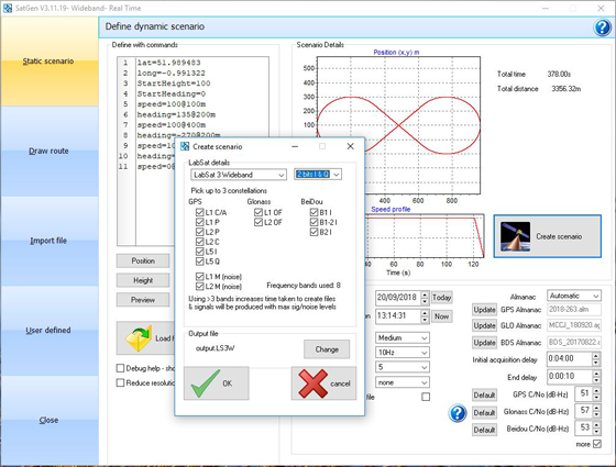
The software now includes simulation of the L2C and L5 GPS signals, meaning that SatGen V3 can be used to create one scenario containing all 13 signals from GPS, GLONASS and BeiDou constellations, the company said.
The simulation accuracy has also been improved — for example, most of the GPS pseudorange residuals are now sub-meter.
Signals that can be simulated simultaneously with SatGen V3 Wideband include:
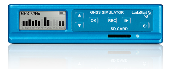
SatGen software allows users to create a GNSS RF I&Q or IF data file that can be replayed on a LabSat, which is based on a user-generated trajectory file. This allows simulators of almost any kind of test, at a set time and date, anywhere in the world.
SatGen complements the LabSat range of GNSS simulators, and is available in single, dual, triple and multi-frequency/multi-constellation versions.
LabSat showcased the upgrade at the ION GNSS+ conference, which took place Sept. 24-28 in Miami.
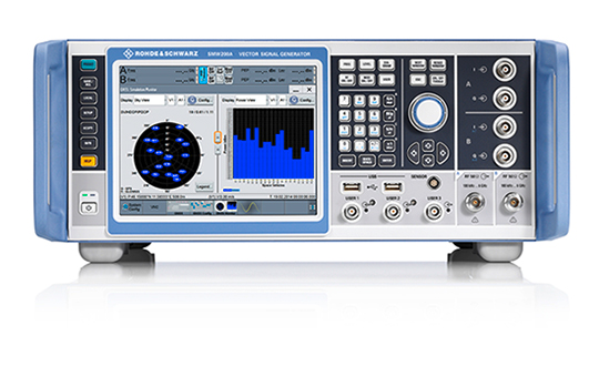
Rohde & Schwarz has added GPS L5 and Galileo E5 simulation capabilities to its R&S SMW200A GNSS simulator.
The R&S SMW200A GNSS simulator is designed for efficient test and characterization of multi-constellation and multi-frequency GNSS receivers. With its additional simulation capabilities for GPS L5 and Galileo E5, the R&S SMW200A enables generation of complex and highly realistic test scenarios with up to 144 channels in the GNSS frequency bands L1, L2 and L5, the company said.
In addition to GPS (L1/L2/L5), GLONASS (L1/L2), Galileo (E1/E5) and BeiDou (L1/L2), the R&S SMW200A also supports signal generation for QZSS and SBAS on L1. The available channels can be routed to up to four RF outputs, so that even multi-antenna systems can be tested.
Apart from its new GNSS simulation capabilities, the R&S SMW200A can generate complex coexistence and interference scenarios with multiple interferers. GNSS signals, noise and all interference signals are generated directly in the instrument. Additional signal sources for external generation of interference signals are not required, resulting in small, compact and simple test setups.
Launched in 2017, the R&S SMW200A can be turned into a high-end GNSS simulator and is able to internally simulate complex interference environments in parallel with GNSS signals.
An increasing number of GNSS receivers are capable of receiving signals on multiple different frequencies, such as L1, L2 and L5. Although this multi-frequency capability, as well as having to process signals from diverse navigation systems such as GPS, GLONASS, Galileo or BeiDou, make the receiver design more complex, they ensure a better quality of service for the end user.
According to the company, multi-frequency and multi-constellation processing not only improves positioning accuracy, service availability and robustness, it also makes the positioning process less vulnerable to interference, jamming or spoofing attacks.
The R&S SMW200A with its new GNSS simulation capabilities will be showcased at the ION GNSS+ 2018 trade show in Miami.
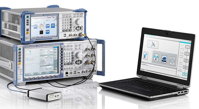
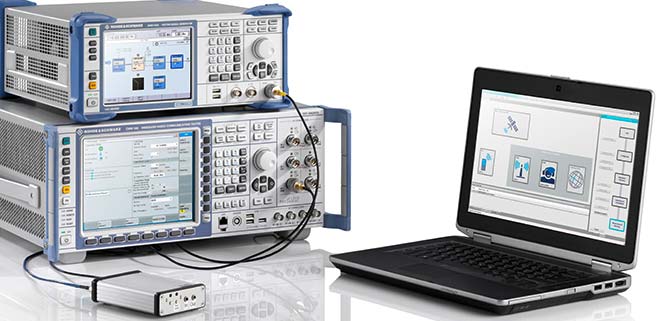
Rohde & Schwarz has expanded the capabilities of its R&S CMW500 wideband radio communication tester and R&S SMBV100A GNSS simulator to support Global Certification Forum (GCF) protocol conformance tests for C-V2X device certification.
Utilizing the Qualcomm 9150 C-V2X chipset solution from Qualcomm Technologies Inc., a subsidiary of Qualcomm Incorporated, the R&S CMW500 acting as LTE network simulator now allows automakers to test C-V2X direct communications (PC5) according to GCF Work Item 281.
3GPP Release 14 specifies the direct communications specifications for C-V2X PC5, which enables vehicle-to-vehicle (V2V), vehicle-to-pedestrian (V2P) and vehicle-to-infrastructure (V2I) safety applications, and does so without a mobile cellular subscription or network assistance and operates in ITS bands 46D (5.8 GHz) and 47 (5.9 GHz).
The new R&S CMW-KK550 test package includes the 3GPP Protocol Conformance tests from LTE-V2V GCF Work Item 281 and LTE-V2X GCF Work Item 282. As recently announced, the R&S CMW-KU514 C-V2X software package on the R&S CMW500 is used to verify data transmission and reception over the PC5 interface in ideal, faded and congested channel conditions. Together, both packages enable Rohde & Schwarz to support C-V2X device testing through all protocol layers.
C-V2X device testing is a significant step towards achieving the goal of having fully connected and autonomous vehicles to improve public safety and increase traffic efficiency.
C-V2X, including direct communications for safety applications, nicely and synergistically complements network-based communications that deliver telematics services and various use cases for connected infotainment and over-the-air software updates.
“C-V2X PC5 radio technology has quickly advanced to a pre-commercial stage, and Rohde & Schwarz is pleased to be the first test equipment vendor to offer a comprehensive C-V2X test suite,” said Anton Messmer, vice president of mobile radio testers at Rohde & Schwarz. “The automobile industry can now verify functionality and performance of C-V2X devices, as well as start device testing as per 3GPP protocol conformance tests.”
“This expanded capability complements our support for European eCall and shows our long-standing support for automotive applications,” Messmer said. “Rohde & Schwarz is committed to providing industry-leading test platforms for C-V2X device performance testing and GCF device certification.”
GMV, Tecnobit and Skydel are aiming to provide corporations, universities and research labs with a reliable, advanced simulation system that closely follows the latest Galileo capabilities.
“Together with our partners at Tecnobit, and taking advantage of SDX’s unique software-defined architecture, we are currently working to add Public Regulated Service (PRS) support to Skydel SDX,” said Manuel Toledo, head of the GNSS Advanced User Segment Solutions Division at GMV. PRS provides position and timing data for sensitive applications that require the highest level of service continuity.
Skydel and GMV are also joining efforts on developing SDX’s capabilities for signal authentication with Galileo Commercial Service and Open Service. The goal of such authentication is to increase the safety level of signals and to avert their falsification or fraud. It is currently a unique feature that only the Galileo constellation can provide, the companies said.
Skydel and GMV are also collaborating on projects that aim to provide signal simulation solutions for Galileo’s second generation (G2G). Galileo’s second-generation satellites are scheduled to be launched in 2025 and beyond.
“With Galileo’s full operational capabilities approaching soon, we must focus on the system’s upcoming G2G services,” said Pierre-Marie Le Véel, business development director at Skydel. “Skydel’s top priority for the European market is to provide simulation tools for the design of these next-generation GNSS devices.”
The partnership among the three companies unites the unique strengths of each organization, GMV said. While GMV brings its expert knowledge of both the European market and the Galileo system and Tecnobit brings its expertise as developer of cryptographic systems, Skydel adds its versatile and extensible GNSS simulator, resulting in a solid technical and commercial synergy for establishing an improved GNSS service offering for Europe.
For several months, Talen-X engineers have been working with the proper channels to develop MNSA (Modernized Navstar Security Algorithm). Talen-X is designing the implementation of MNSA for its flagship products: BroadSim and BroadSim Anechoic.
BroadSim is a software-defined GNSS simulator made to accomodate engineers who test systems requiring encrypted signals, jamming and spoofing. According to the company, BroadSim Anechoic leverages the same software-defined capabilities, scaled to enable powerful anechoic chamber simulations.
Encrypted signal simulation is being used to support many military testing applications, both in the lab and in the field. BroadSim can simulate many signals including the legacy GPS Y-Code and the modernized GPS Advanced Encryption Standard (AES) M-Code, the company said.
Other companies use costly and outdated field programmable gate arrays (FPGAs) to upgrade their systems. With Talen-X, users can opt for a simple license upgrade to enable the new GNSS signals to include GPS AES M-Code and eventually MNSA on their BroadSim device.
With the addition of MNSA, engineers testing capabilities will reach the closest they’ve ever been to simulating real-world scenarios, ensuring complete confidence in the accuracy and resiliency of the test unit.
From April 1 onward, car manufacturers are required to equip new vehicles for sale in the European Union with an eCall module. In the event of a serious accident, this emergency call system automatically sends data to the uniform European emergency phone number 112 to facilitate faster response by emergency services.
The independent test house CETECOM has now certified the eCall test solution from Rohde & Schwarz, which can be used to simulate a public-safety answering point, in accordance with the EN standard. This puts manufacturers and suppliers in a very good position for acceptance tests of their installed emergency call systems, and the Russian emergency call counterpart ERA-Glonass can also be tested with an extension.
The Rohde & Schwarz eCall test solution is the first of its kind to be certified by an independent test body, according to the company. CETECOM has examined the implementation of the eCall test public safety answering point (PSAP) in the Rohde & Schwarz solution for the pan-European emergency call system and certified it as compliant with the CEN EN 16454:2015 standard. This is a prerequisite for tests compliant with Commission Delegated Regulation (EU) 2017/79.
CETECOM has been officially designated as a technical service for eCall by the German Federal Motor Transport Authority. After March 31, manufacturers must equip new vehicles for sale in the EU with an eCall module. The R&S CMW-KA094 test solution is the first independently certified test PSAP system based on a wireless communications test platform.
Rohde & Schwarz thus offers a compact solution for reproducible end-to-end functional tests and standard-compliant conformance tests of eCall and ERA-Glonass modules. The prescribed conformance tests can be performed with the test solution.
Manufacturers and suppliers use these tests to check whether the installed modem properly initiates an emergency call in the event of a motor vehicle accident, correctly acquires the relevant data and sends it via the mobile network, and is able to establish a voice connection to the PSAP.
Test houses and vehicle manufacturers use this solution for type approvals and for other tests requiring the emulation of mobile networks, such as location-independent testing of a car telephone.
The certification of an eCall test solution by an independent body demonstrates that Rohde & Schwarz is a reliable partner for the automobile industry — the majority of global OEMs use the R&S CMW500 wideband radio communication tester and rely on the field-proven Rohde & Schwarz test solution.
The company is also developing test features for the next-generation eCall over LTE system and making the corresponding solution fit for the future and for testing new vehicle telematics units.
Along with eCall, Rohde & Schwarz supports the automobile industry with test solutions for V2X communications (from a vehicle to other users).
The eCall test solution based on the R&S CMW500 platform in combination with the R&S SMBV100A GNSS simulator is the first to be certified by CETECOM. (Photo: Rohde & Schwarz)
Technical basis. The R&S CMW-KA094 application software specifically developed for eCall is based on the R&S CMW500 platform in combination with the R&S SMBV100A GNSS simulator.
The software simulates a PSAP and controls the R&S CMW500, which emulates a mobile network in the lab. It also controls the GNSS simulator, which provides the position data of the accident location.
The R&S SMBV100A additionally supports the GNSS receiver performance tests in accordance with Commission Delegated Regulation (EU) 2017/79 Annex VI.
The eCall test solution can be fully automated with the R&S CMWrun sequencer software for further conformance tests, enabling users to directly utilize ready-made test sequences for eCall and ERA-Glonass modules compliant with ETSI TS 103 412, CEN EN 16454 or GOST 33467. This additionally facilitates demonstration of the functional capability of the overall system in accordance with Commission Delegated Regulation (EU) 2017/79. For more information on how to test eCall and ERA-Glonass system modules, visit www.rohde-schwarz.com/ad/press/ecall-cetecom.
IFEN GmbH’s Titan GNSS simulator has up to 256 channels (and 1024 multipath channels) and up to 4 RF outputs per chassis, providing flexibility and outstanding performance, according to IFEN.
The extra complexity and cost of using multiple signal generators is avoided, improving reliability without compromising on functionality, IFEN said in a news release.
The innovative design of the NCS Titan allows users configure channels for any GNSS signals and allocate those channels to any of the RF outputs fitted. This flexibility enables the same simulator hardware to be used for an extensive range of tests, for all types of GNSS applications.
The NCS Titan GNSS simulator by IFEN.
The NCS Titan sets new standards in the field of GNSS Simulation, in terms of fidelity, accuracy, dynamics, iteration rates and reliability, the company said.
“The launch of our brand new NCS Titan GNSS Simulator represents another milestone for our NCS GNSS simulator products,” explained Günter Heinrichs, head of customer applications at IFEN. “This shows clearly once again our commitment to ongoing product enhancement and dedication to providing our customers with best GNSS test equipment on the market.”
The NCS TITAN GNSS Simulator has been developed in cooperation with WORK Microwave GmbH, Germany.
“Prepare for Tomorrow: Find Vulnerabilities Today” was the title of our wide-ranging webinar in July that focused on GNSS signal simulation for jamming and spoofing scenarios. We did not have time to address all the questions posed by the audience, so we return to them here.
Q: While testing receivers, realistic scenarios for jamming and spoofing are very important. What is the typical approach to set the number of interference sources, their type and main signal parameters?
Two different approaches are common, those involving the use of an anechoic chamber and those which are lab-based. Each approach has its limitations and merits. Each approach must address the number of significant interferers, their signal powers and the waveforms of the interference signals. Each must also consider the geometric arrangement of these interferers relative to the antenna under test and relative to the simulated constellations under test.
Changes in signal phase, signal Doppler and signal power are as important for the interference signals as they for the wanted GNSS signals. These changes are caused by the simulated motion of the vehicle and potentially the motion of the interferers. These changes should also include the impact of terrain surrounding the vehicle and the interferers, and also the gain and phase patterns of the receive antenna on the vehicle and the transmit antennas on the interferers. Some interferers might be discounted from the significant set due to their signals being masked from the vehicle by the terrain or antenna patterns or by them being too far from the vehicle to have an impact. These interference signals may become significant as the scenario progresses due to vehicle or interferer motion.
Simulator graphical user interface. (Image: Spirent Federal Systems)
Q: In GNSS navigation systems for commercial applications, what emphasis of design effort should be on anti-jamming/anti-spoofing over improving the navigation accuracy?
Commercial applications is a broad area, so it will depend on the particular application as to whether it needs more accuracy or more resiliency against AJ/AS, but in general, the accuracy of GNSS is fairly mature. Standard GNSS offers accuracies on the order of ~1 meter. Centimeter accuracy can be achieved with differential or real-time kinematic (RTK). Multi-constellation use can increase availability in areas with limited sky view such as urban canyons. Multi-frequency can aid in the reduction of multipath and improve accuracy. If the application needs accuracy, these features are readily available.
However, integrity and resiliency are growing needs in commercial applications, especially ones that are in critical operations. Much more can be done to detect jamming and spoofing than what is in standards GNSS receivers today. In our systems, we include an additional software layer called BroadShield, which monitors internal state variables of the receiver, and will alarm on detection. Additional sensors combined with the GNSS receiver such as an inertial measurement unit (IMU), magnetometer, odometer, or even the much stronger Satellite Time and Location (STL) signal offer augmentation during periods of GNSS denial, or in the case of spoofing, authentication of the navigation solution.
While both jamming and spoofing are intentional attacks, they are highly different in their set-up and serve very different purposes. Due to their simplicity, most jamming attacks can be mitigated thanks to adaptive filtering or pulse blanking. On the other hand, spoofing is a malicious attack, highly complicated, and requires knowledge of the GNSS signal structure as well as precise timing and positioning.
The question is thus whether one should emphasize navigation accuracy over the ability to output a position (jamming case) or the possibility to output a completely erroneous position (spoofing case). The answer lies, obviously, in the end application and the coupling of GNSS receivers with other systems. High-precision non-life-critical applications should emphasize navigation accuracy while implementing simple jammer filtering strategies. Life-critical applications, being often coupled with other systems, should ensure the reliability of the solution even if that means being unable to compute a position due potential threats.
Q: Do you have GPS/inertial navigation system (INS) test capabilities?
The CAST-3000 EGI integration system produces GPS RF signals commensurate with simulated IMU sensor data to provide repeatable testing in the integration laboratory for a wide range of military and government applications.
CAST GNSS/INS simulators generate high-fidelity signals required for emulating the legacy GPS signals as well as those used by next-generation navigation technologies. This is because our sole business focus is supplying GNSS simulators, GNSS/INS test equipment, and GNSS/INS support services to government and military avionics laboratories, prime contractors, and GNSS receiver manufacturers. For 35 years we have provided off-the-shelf products to both the government and U.S. major defense contractors.
CAST EGI integration tools are used by Northrop Grumman and Honeywell and are now also being used in integration laboratories worldwide. Our equipment supports system integration in major weapons platform labs and development at major military contractor labs. CAST simulators produce high-quality, accurate signals that are used in government, military and commercial labs around the globe.
Our NCS TITAN GNSS simulator is able to emulate the presence of IMUs and micro electro-mechanical systems (MEMS) sensors with the optional available real-time IMU/Sensor Emulation Package (SEP). The SEP upgrades the TITAN to support the simulation of inertial sensors, which nowadays are implemented as MEMS, among others, and of other common aiding sensors. To obtain more accurate positioning for location-based services and navigation, GNSS chipset and receiver manufacturers as well as system integrators combine more and more GNSS navigation with such sensor fusion or signals of opportunity.
The optional SEP enables controlled and progressive testing of sensor-fusion algorithms when used with NCS Control Center operating software. This software supplies the SEP with an internally- or externally-generated center-of-gravity (CoG) trajectory for the device under test.
The various sensor models to be emulated by the SEP run within the Control Center software. The device under test (vehicle) input trajectory at the CoG passes through the sensor model, which in turn generates the appropriate sensor output, by taking into account the corresponding error model for each sensor defined.
We have added the capability to emulate INS/IMU data in addition to GNSS signals to our Constellator simulator, to offer to the customers a complete testing platform. Constellator can simulate up to six gyrometers and six accelerometers. The attitude of each sensor is defined with respect to the vehicle axes. Deterministic errors can be configured to simulate the axis misalignment and scale factors, and biases can be defined in order to simulate realistic sensors. Stochastic error models are also available such as random walk or Gauss-Markov models for each sensor (gyrometer or accelerometer) to improve the sensor emulation fidelity.
Q: Do you have detailed scenarios for jamming and spoofing in timing use of GNSS receivers, that is, involving time synchronization for telecommunications companies?
The simulated jammer’s signal specification must be very flexible in order to faithfully simulate real-world jamming events. For example, the jammer’s spectral shape should be flexible enough to simulate a Blue Force electronic attack (BFEA) on a GNSS receiver.
Also, the simulator should be able to simulate dynamic scenarios by varying the power of the jammers as a function of their trajectories and as a function of different antenna patterns.
Sometimes when testing receivers, the simulated jammers should replicate pre-recorded waveforms from real world. The ability to play back the pre-recorded IQ-baseband signal in conjunction with GNSS signals is another powerful feature of a simulator. Simulation of spoofing attacks on a GNSS timing receiver is only possible when the GNSS simulator provides fine-grained control of transmitted signal. This includes controlling the offsets on the pseudoranges with additive ramps, as well as individual signal power levels at very precise points in time.
Also, the GNSS simulator must be able to synchronize itself with the live sky’s GNSS signal. Another way to achieve realistic spoofing is to use two simulators controlled independently (that is, full control on constellation, navigation message, propagation time offset, power and so on).
FIGURE 1. Real-world jamming simulation must take into account key factors such as varying jammer power, as a function of their trajectories and antenna patterns. (Image: Skydel)
Q: Please discuss how to simulate a smart spoofer that would generate a replica of a constellation (or all constellations) and then produces two full RF transissions: one that is the true signal, and a strong spoofed signal that pulls the receiver to a false location. Can you simulate the two full multi-band RF ensemble?
Two artificial synchronized scenarios could be created using SatGen signal generator software that can reproduce the GNSS signals from a number of constellations. The user could create two separate signal streams, both starting at exactly the same position and time and using the same constellations, chosen by the user.
The second scenario could then be set to diverge away in position from the first scenario, while staying perfectly synchronized in time. The signal-to-noise ratio of each scenario could be adjusted independently of each other to simulate a spoofing situation where the spoofing signal is much stronger than the real signal. A file containing this twin scenario can be replayed using a LabSat Wideband with two separate RF outputs, each synchronously replaying the two different scenarios. This would closely simulate the actions of a smart spoofer, but in a completely repeatable, and controllable manner.
This could be accomplished by either combining the output of two of our CLAW GPS simulators, or by combining the output of a single CLAW simulator with live-sky signals using passive industry-standard splitters/combiners. The CLAW is able to receive a custom ephemeris download in RINEX format to match either the spoofed live-sky constellation, or to generate a synthesized constellation in the case where two CLAW simulators are being used.
The simulator has a wide RF power adjustment range of over 45-dB, allowing the spoofing signal to be gradually introduced to the primary GPS constellation RF signal. This spoofing simulation could be accomplished with better than 0.5 meter peak-to-peak positioning accuracy and better than 5-ns real-mean-squared (rms) typical UTC (GPS) offset unit-to-unit, allowing the victim receiver to be pulled off of its true (live-sky) position with very high accuracy. Typically, GPS receivers are spoofed easily as long as the UTC timing synchronization is 500-ns or better between the live-sky and spoofed signals.
Timing synchronization to the spoofed victim GPS signal to within nanoseconds is achievable through the external 1PPS reference input, the simulator accepting a position, navigation and timing (PNT) fix in real time via its NMEA serial and 1PPS inputs. This allows capturing a moving victim receiver by estimating its momentary position, then ramping up the spoofer power, and then presenting the victim receiver with alternate position information as required (see Figures 2 and 3).
High position and timing accuracy between the spoofed and live-sky signal is important to prevent and mitigate spoofing detection via UTC phase or position jumps that could happen when the receiver gradually or quickly switches over to the spoofed satellite signals.
FIGURE 2. Spoofing attack on a GPS receiver using a CLAW simulator to spoof a live-sky antenna signal. Initially the spoofer was phase- and frequency-synchronized to UTC(GPS), then spoofer RF power is ramped up, and once the victim GPS receiver is captured, a frequency offset is added to UTC(Spoofer), which pulls the system off-phase. (Figure: Jackson Labs)FIGURE 3. Simulating a spoofing attack on a timing application where the spoofer does not know the exact victim antenna location with certainty. The resulting antenna position offset error (50 meters in this simulation) still allows the victim receiver to be captured, and then causes a time error as satellites move in and out of view even with the spoofer being synchronized to UTC(GPS) at all times. This error is clearly visible in the resulting UTC(Spoofer) output from the victim receiver equipment. (Figure: Jackson Labs)
Q: We want to correctly model and simulate effectiveness of various anti-jamming (AJ) and anti-spoofing (AS) solutions to make informed decisions about which AJ/AS solution is most effective for a specific mission and interference scenario. How can you help?
Live-sky testing on a jamming/spoofing range provides a wealth of data, and reassurance that the system under test does work as intended. Record and playback systems (RPS) under live-sky conditions can allow further evaluation back in the lab, after the live-sky tests are complete. Performance parameters of the RPS may degrade the validity of the signal when played back; signal bandwidth and bit-depth are absolutely key, for example. Recordings that use too few bits will degrade the dynamic range of the recorded signals, so significant care should be taken when selecting an RPS.
Either way, under live-sky or with recorded live-sky, you get what you get. It is extremely difficult to predict what the test parameters actually are. It is perilous to attempt to alter the test parameters after the event. Lab-based or anechoic chamber-based systems have their limitations, but they are repeatable, predictable and tweakable. Again, performance parameters of the simulation system play a key role in the validity of the testing. The ability to calibrate the simulation system to give a repeatable, predictable performance is as important as the realism of the simulation. Carrier-phase accuracy/repeatability among antenna elements and signal timing accuracy are important parameters when evaluating AJ and AS systems.
Q: We had a receiver where the time stamp for any location report would drift off progressively, up to an hour off of the known true location. What might contribute to this? We do not believe this was an intentional threat, but an artifact of nearby electronics or other system conditions. It actually occurred on a pivot irrigation arm in motion, with substantial vibration. The receiver was electrically isolated. The results were repeatable on the pivot arm, but not on our vibration table.
Interesting problem with no obvious answer. Even the worst oscillator will take many months to drift off by up to an hour with no GNSS, even under horrible vibration conditions, so this is an unlikely cause. Is it drift or a jump in error? Nearby electrical noise could cause GNSS denial (jamming), but not erroneous data. That requires spoofing. If you have no reason to believe that it is intentional, that makes spoofing unlikely, but still possible. Is a GNSS repeater or a record/playback GNSS tester operating in the area? These are spoofers, even if they are unintentional.
If this is a precision agriculture application, then an RTK reference station transmitting erroneous data could be the cause. What time-stamping format is used: local time or UTC? An unlikely but possible scenario is the unit is changing time zones so local time jumps an hour. Is there a processor/software app between your output and the actual GNSS receiver? This could introduce errors. What is the position output indicated when the time drift occurs? The best way to diagnose this is to record the time and position output as log files using a laptop PC connected to the serial data.
Q: Do your simulators work as well for testing handheld, consumer-grade GPS? Please discuss the differences in testing techniques or approaches for high-precision vs. mass-market receivers?
We have a range of simulators suitable for all levels of GNSS testing. If you don’t need the high fidelity and wide bandwidth of the LabSat Wideband, then the entry level LabSat 3 will also work with any GNSS device including handheld consumer-grade products.
To fully explore the performance of high-precision receivers, including multipath effects and P-code reception, a wider bandwidth and a greater number of bits would be required to capture and replay all of the available signals. For these applications, we recommend a bandwidth of 56 MHz and at least 4 bits of resolution.
For testing of consumer-grade, handheld devices with simpler RF front ends, we recommend a much reduced bandwidth of around 9 MHz and only 2 bits of resolution. This smaller bandwidth and fidelity will easily reproduce the majority of real-world conditions, and the resulting data files will be much easier to handle.
FIGURE 4. Simulator graphical user interface. (Image: Racelogic)
Q: How many GNSS signals can a software-defined radio produce?
The theoretical limits of a software-defined radio (SDR) are based on four distinct characteristics of the SDR: the digital-to-analog converter’s (DAC’s) bit resolution, the maximum sampling rate, the bandwidth and the number of RF outputs. With most SDRs, available bandwidth is defined by the sampling rate.
With a 16-bit DAC, there is enough dynamic range to generate up to 50 GNSS signals and hundreds of multipath echos (with more than 60 dB of range to accommodate different signal power levels) per RF output.
For example, with a sampling rate of 50 MSps, a 40-MHz wide signal — combining GNSS constellation signals such as GPS L1 C/A, Galileo E1, GLONASS G1 — can be generated. Nowadays, SDRs can have two or more RF outputs and are able to operate with sample rates of 100 MSps or higher. By distributing the GNSS signals across different RF outputs, the entire GNSS spectrum can be covered at a relatively low cost in terms of hardware.
A handful of SDRs can easily be synchronized to form multiple RF output systems. In such cases, the complete range of GNSS signals for all visible satellites can be generated at the same time.
Q: In a dual-frequency receiver would it be possible to still use L1 spoofed/jammed with L2 clean to get an accurate position? Is it possible to do a combination between the two signals in order to save the spoofed/jammed L1?
In principal, it is still possible to use L1 spoofed/jammed with L2 clean in a dual-frequency receiver to get an accurate position. Such receivers are available as off-the-shelf products. These receivers use a special algorithm to detect if a GNSS frequency band is spoofed/jammed and automatically switch over to the clean frequency band. However, this principle can only be applied if the entire GNSS spectrum is not completely jammed. Whether a dual-frequency receiver can still use L1 spoofed/jammed with L2 clean to get an accurate position is therefore finally basically dependent on the overall bandwidth of the interferer/jammer.
With IFEN’s TITAN simulator, it is possible to easily create the corresponding simulation scenarios for the real-time simulation of realistic test scenarios to test the robustness of GNSS receivers against interference/jamming and also spoofing. In doing so, various static and dynamic interference/jamming sources are supported by the simulator’s software.
It is possible to achieve a PNT solution using L2 signals only. This requires reception and decoding of either the military L2 P(Y) signal, or reception of the new but still pre-operational L2C commercial signal. Codeless or semi-codeless commercial L1/L2 receivers rely on tracking the carrier phase on L2 to be able to mitigate effects such as solar flares and ionospheric errors; however, they are not capable of generating a PNT solution with L2-only reception as would be the case under this spoofing/jamming scenario.
P(Y) signal reception on L2 typically requires reception of the coarse acquisition (C/A) signal on L1 prior to tracking P(Y) unless the receiver has its own internal (atomic) time-base synchronized to UTC to the sub-microsecond level.
On-Demand Webinars
Simulation against Jamming and Spoofing: With cyber attacks on the rise, it is more critical now than ever to thoroughly test GPS and GNSS systems against jamming and spoofing.
The SMW200A GNSS simulator adds a high-end solution to the Rohde & Schwarz portfolio of satellite navigation system simulators. It can be extended to up to four RF outputs and allows GNSS signals to be simulated simultaneously in multiple frequency bands for multiple antennas.
The SMW200A can internally simulate a complex interference environment in parallel with GNSS signals.
The instrument was unveiled at ION GNSS+ 2017, which took place Sept. 25-29 in Portland, Oregon:
An increasing number of GNSS receivers are able to process signals from diverse navigation systems such as GPS, GLONASS, Galileo or BeiDou in several frequency bands — and in some cases, with several antennas in parallel — to improve positioning accuracy.
Accuracy can be further improved with differential GNSS (DGNSS) techniques. These techniques are used in applications such as autonomous driving, and they are indispensable for precise and reliable positioning of aircraft during landing approaches. The GNSS receivers used in these applications must undergo extensive tests before deployment in vehicles or aircraft.
The new R&S SMW200A GNSS simulator now offers an innovative test solution for easy generation of complex and highly realistic test scenarios for a wide variety of GNSS applications. To test multi-frequency and multi-antenna systems, users now have access to 72 GNSS channels that can be assigned to up to four RF outputs.
The R&S SMW200A can generate QZSS and SBAS signals as well as GPS, GLONASS, Galileo and BeiDou signals. This solution enables users to quickly and easily verify the position accuracy of their receivers under realistic conditions.
The R&S SMW200A also has an internal noise generator and can generate complex interference scenarios with multiple interferers. All signals (GNSS, noise and interference) are generated directly in the instrument. Additional signal sources for external generation of interference signals are not necessary, considerably simplifying test setups.
No external computer is needed to configure and operate the R&S SMW200A. The integrated, intuitive graphical user interface (GUI) allows users to generate GNSS scenarios quickly and easily. Thanks to the multitude of instrument options, the solution can be optimally adapted to individual user requirements.
The R&S SMW200A is an extensible, future-proof platform ready to implement future test requirements such as testing new GNSS signals.
The R&S SMW200A with the new GNSS options is now available from Rohde & Schwarz.
Spirent Federal Systems, a provider of GPS and GNSS simulators, has begun developing MNSA-capable GNSS simulators for the Modernized Navstar Security Algorithm.
Spirent Federal is developing software that will support M-code using MNSA. M-code is an updated GPS military signal that is being rolled out as part of the modernization of the current GPS constellation.
GPS modernization began in 2000 when the GPS Selective Availability feature was set to zero. Since that time, the U.S. Air Force has been working on newer generation satellites that will transmit new civilian and military signals.
Until now, AES and SDS have been the only methods authorized to be used within a GNSS simulator to produce M-code.
Spirent Federal Systems has been a provider of AES M-code and SDS M-code capable simulators for many years, but as the long awaited MNSA M-code signals become available, Spirent Federal Systems will be making this option available to authorized users on the GSS9000 series simulator.
Averna has entered a strategic partnership with M3 Systems to distribute M3’s StellaNGC GNSS Simulator on National Instruments’ VST platforms for the infotainment segment of the automotive market.
M3 Systems’ GNSS simulator, based on National Instruments’ Vector Signal Transceiver (NI VST), will now be available as part of Averna’s AST-1000 platform, extending its capability to navigation and GNSS testing.
Launched in July 2016, the AST-1000 is an RF solution designed for radio, navigation, video and connectivity testing. Also based on the NI VST, the software-defined AST-1000 supports all common infotainment RF signals, including AM/FM, DAB, RDS, HD Radio and Sirius/XMas, as well as GNSS navigation.
The combination provides a comprehensive solution and enables unprecedented applications for the testing of infotainment systems.
M3 Systems’ GNSS simulator is a good fit to extend the capability of the AST-1000 for navigation testing because both instruments are based on the NI VST, the companies said.
Averna is aiming for an all-in-one platform for the complete validation of infotainment systems, including radio, navigation, audio/video and connectivity testing.
The Averna AST-1000 is available to customers worldwide.
A: For UAV simulation, a record-and-playback system is obviously less applicable, as the user is more interested in defining system operability within a range of parameters rather than in any generalized case. A high-dynamic user performance is required, but users should look at a simulator’s static performance first to ensure high accuracy. Interference, both intentional and unintentional, is the main challenge. At least two RF outputs are required to facilitate development of differential and RTK algorithms and to simulate multiple antennas.
A: Safety and compliance to existing regulations are the key factors for UAVs. To evaluate them in harsh environments, the GNSS simulator should push the UAV’s navigation system to the limits. The simulator should allow for creation of complex scenarios with drastic changes in satellite constellations, signal/frequency diversity and signal quality. The simulation of multipath signals and interference should account for relative dynamics between the UAV and the environment. Importing six-degrees-of-freedom (DOF) complex trajectories is another important factor to consider.
A: The UAS simulator must support realistic flight profiles with the ability to integrate autopilot controllers. Affordable simulators need to support closed-loop simulation so the guidance logic will have an impact on the simulated signals. Another critical aspect to consider is the ability to integrate the threat signals enabling counter-UAS testing. We must have a simulation capable of supporting all signals present in the environment — PNT, threats and communications.