Tag: GNSS simulator

  • Highlights from the Grand-Daddy of All GNSS Technical Conferences

    Highlights from the Grand-Daddy of All GNSS Technical Conferences

    Tony Murfin
    Tony Murfin

    The ION GNSS+ 2015 Conference once again fielded a jam-packed agenda of papers on subjects  from world-wide constellation updates, through GNSS integrity, indoor navigation demonstrations, multi-constellation/function chipsets, interference mitigation and jamming detection, privacy issues, and many other very interesting subjects.   That’s GNSS+ in the conference name, as in “plus,” denoting the many other positioning, navigation, and timing technologies it covers.

    Most papers contained advanced academic research, but there were also several new industrial releases. This year ION divided and clearly differentiated sessions between “System and Application Tracks,” that is, those with more direct industry content, and “Peer-Reviewed Tracks,” the so-called “pure” research.

    As always, some of the most valuable takeaways of attending ION come from the numerous unrelated, off-the-record corridor conversations: an essential element, always spontaneous and much anticipated, but something that cannot be clearly identified nor put into the program.

    The conference seemed to have around the same number attendees as last year with about the same number of exhibitors, even though a few of the big booths were missing. Paradoxically, some exhibitors privately said they did better and more business this year, even with fewer attendees, according to their estimates.

    SPIRIT Navigation from Moscow did not have a booth, but Ruslan Budnik made sure to fill my notepad with lots about their technology, products and initiatives. They are among several companies working to add indoor navigation capability to smartphones, using existing onboard sensors and new intelligent software. Their solution concurrently uses multiple technologies including geomagnetic fingerprinting, pedestrian dead reckoning, and map matching, but does not rely on an installed beacon infrastructure. A Spirit app allows store operators to quickly map Wi-Fi and Bluetooth signals and collect a Magnetic field map which matches the floor plan of the store’s venue. Spirit claims an accuracy of around 1 meter, which Ruslan proceeded to demonstrate to me in the corridors around the ION meeting rooms.

    The plenary session on Tuesday night was very interesting with a presentation on the results of NASA’s planetary exploration over the last several decades, by Dr. James Green, NASA Director or Planetary Science. I learned a lot about our solar system; much more out there than one suspects, and much to be revealed in the next few years!

    GPS World editor Alan Cameron once again led a preview of the planned sessions for the week, with each session chair constrained to a 5-minute rapid-fire presentation aimed at enticing as many attendees as possible. Interesting and somewhat humorous at the same time; we still got a flavor of what was to come in each track.

    On Wednesday I was fortunate to be able to interview several show exhibitors.  Some of these you will also find in video footage on the magazine’s website, speaking to you straight from the show floor.

    Photo: Skydel

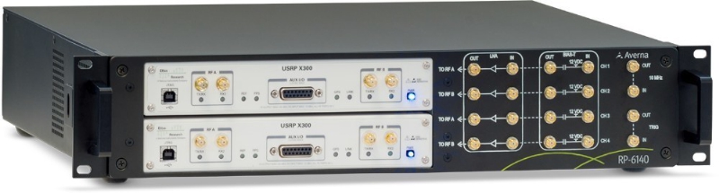
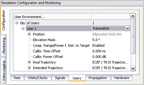
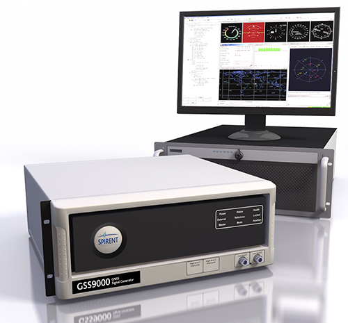
    Skydel is a relatively new exhibitor, working with Averna, both from Montreal, Canada. Averna makes signal analysis hardware on which Skydel installs software-based simulation of GNSS signals. Skydel’s objective is to be able to make their solution so affordable that every engineer could have one of these record and playback simulators on their desk, rather than having to schedule time on a central, shared multi-function simulator. An exciting new-entry product developed by an energetic group of people with a high level of ingenuity; hopefully they will succeed.

    DLR antenna prototypes
    DLR antenna prototypes

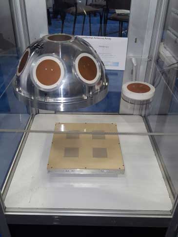
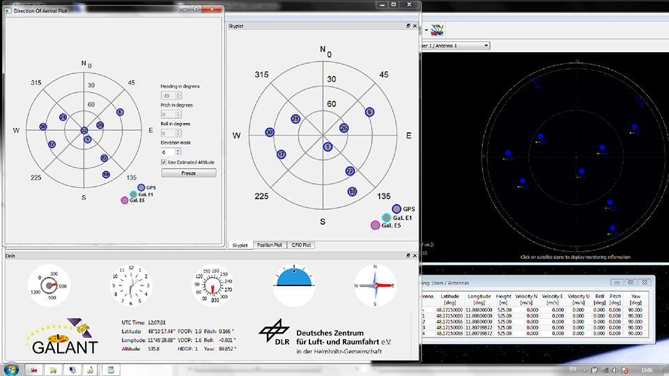
    A robust receiver initiative from Deutsche Zentrum für Luft- und Raumfahrt (DLR), the German Aerospace Center aims to demonstrate that jamming and interference detection and mitigation can be achieved much more effectively than just at the RF level. Their processing goes deeper with such features as knowing that a source from a particular direction isn’t aligned with the current constellation, so it’s a jamming/interference suspect. Their conformal antenna development attempts to meld an antenna configuration with their signal processing capabilities. DLR is looking for partners to put these developments into commercial receiver applications.

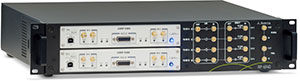
    ComNav has a new K700 family of receivers: K-700 GPS L1, Beidou B1 and Glonass L1 80 channel receiver — added to their K-708 dual frequency 198-channel dual-frequency version. The M300 Pro GNSS Receiver package includes a weather-hardened package, multiple interfaces which enable remote internet control and data access, memory and a rechargeable back-up power supply. ComNav claim the M300 Pro has been selected for the Chinese CORS network. ComNav also anticipates a name change in the near future: SinoGNSS will be their new company name.

    Harxon-antennas-and-radios-W
    Harxon antennas and radios
    Unicore UB370 Beidou/GPS/Glonass multi-frequency OEM receiver
    Unicore UB370 Beidou/GPS/Glonass multi-frequency OEM receiver

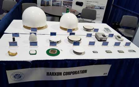
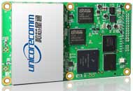
    Harxon gave us an overview of their wide range of antenna and radio products, while Unicore in the next booth described their single and dual frequency receivers which they are now promoting extensively in North America.

    NovAtel GAJT antijam systems
    NovAtel GAJT antijam systems

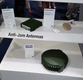
    As usual, NovAtel had a wide range of products on display. I was impressed that the mil-spec GAJT anti-jam product-line has now undergone testing by both the U.S. and Canadian military, and that the GAJT-AE is now flying and providing guidance protection in hostile jamming environments. Once again there were mentions of NovAtel receivers and antennas being used for research in several technical papers at the conference.

    Septentrio continues to make further inroads into the high-precision GNSS receiver market, and announced several new key initiatives. The company has been selected by UNAVCO as the Geodesy Advancing Geosciences and EarthScope (GAGE) facility preferred vendor for next-generation GNSS reference station products. UNAVCO ( ) is a non-profit university-governed consortium, facilitating geoscience research and education using geodesy.

    AsteRx-U dual antenna receiver
    AsteRx-U dual antenna receiver

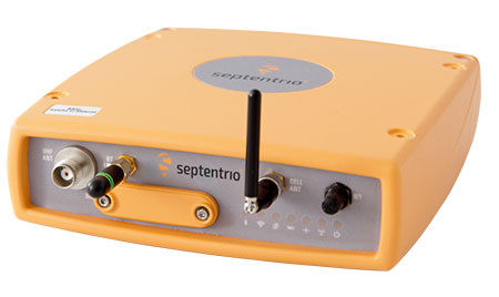
    Septentrio is developing a next-generation reference receiver with UNAVCO’s inputs and evaluation feedback for the purpose of upgrading and renewing their GNSS networks. Septentrio also launched the AsteRx-U and the AsteRx-U Marine multi-constellation dual antenna receivers which incorporate the latest GNSS tracking and positioning algorithms and interference mitigation along with integrated UHF radio, Wi-Fi, USB, Bluetooth, cellular connectivity, and a spectrum analyzer which provides users with their interference profile.

    Indoor Navigation

    ION’s annual Indoor Navigation Demo session on Wednesday afternoon turned out to have more slides and pre-recorded testing content than actual demonstrations. The participants included Nokia HERE, Rx Networks, SPIRIT Navigation, TRX Systems, Broadcom, Indoors and Combain.

    HERE was able to initially demonstrate some indoor tracking of an equipped cellphone, but the display for the audience appeared to quit after a short period. They did provide a link to allow attendees to download their software and try it for themselves.

    Rx Networks is apparently focusing on self-location for indoor guidance assets, and ran a pre-recorded demo of ‘Zed’ in a Vancouver Mall – but the vertical tracking display part of the video was completely washed out for the audience.

    SPIRIT Navigation ran a recording of the demo I had witnessed earlier – a quite effective, working indoor nav application on a smartphone – and then walked around the demo room, but wasn’t able to show real-time results.

    TRX Systems ran a very effective real-time demo and was able to show the audience the path of their ‘walker’ as he meandered around the Conference Center, changed levels and eventually returned on cue to the demo room. They use crowd sourcing to build an initial map which then constrains sensor data from standard sensors, similar to several other presenters. This appeared to be the winning demonstration for this year’s indoor nav demo. We did hear later that they were not using sensors within the smartphone, rather a separate TRX device attached to the belt or the ‘walker’.

    Broadcom ran an effective demo, albeit with considerable lag between actual and displayed position and frequent jumps between points, presumably due to the same delay problem. This was attributed to the display system used to present to the audience. They also ran a second short in-room demo which was more effective and more real-time, but apparently not as accurate as TRX from the displayed results.

    Indoors also use ‘radio’ fingerprinting with GNSS data as a back-up, and Wi-Fi, BLE, magnetic and inertial data fusion along with dead-reckoning. Their recorded demo was quite effective.

    Combain has a system which is required to be world-wide interoperable for machine-to-machine asset location, so they are focused on using cell and Wi-Fi IDs for navigation, with databases containing 64 million Cell IDs and 726 million Wi-Fi location IDs. They claimed accuracies of 200 meters for urban areas and 40 meters for rural. These accuracies are not suitable for indoor location so no demonstration was provided.

    Pico-second test results (Click on the image to enlarge it.)
    Pico-second test results (Click on the image to enlarge it.)
    Pico-second test results
    Pico-second test results

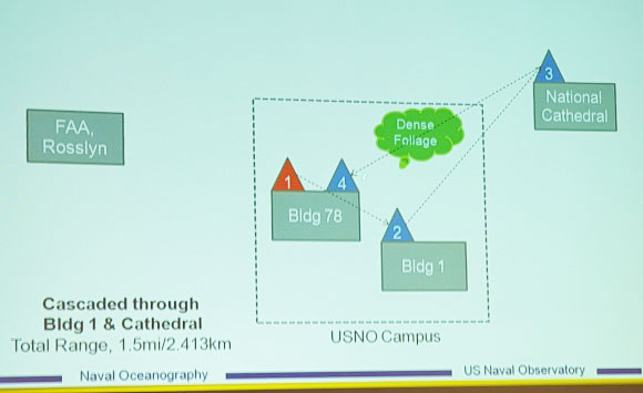
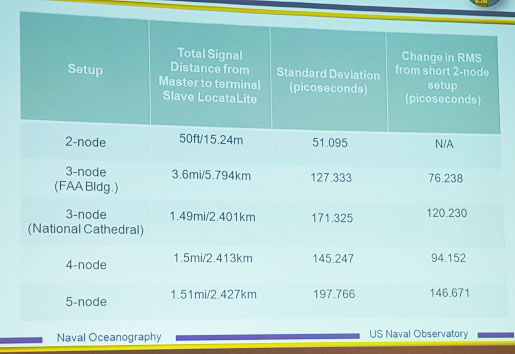
    Later, I managed to catch a paper which Locata had recommended, which involved a number of Locata networks used by the U.S. Naval Observatory to demonstrate time and frequency transfer using the USNO Time Standard, with some highly accurate results: picoseconds! This paper forms the basis of GPS World magazine’s October cover story, providing more on these significant time-transfer and synchronization findings.

    GRIFFIN-Central-Processor-W
    GRIFFIN Central Processor & Node Antenna Electronic Units

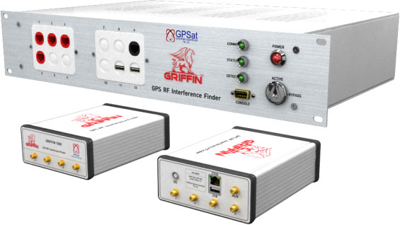
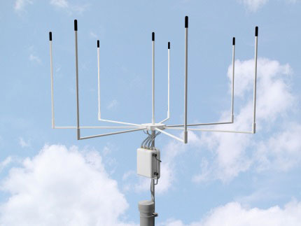
    Another significant paper was presented in the Interference & Spectrum issues track. GPSat Systems Australia has been working for some time to implement a jammer/interference detection and localization system. The GRIFFIN 1000 system uses both Angle of Arrival (AoA) and Time Difference of Arrival (TDOA) to locate interference sources. GPSat claims that RF interference source in the GPS L1 band can be detected and geo-located to accuracies of a few meters within a few seconds. The system is already in production, with final production field testing underway, and customer deliveries scheduled for November.

    Multi Element Antenna Array and Node Electronics
    Multi Element Antenna Array and Node Electronics

    As ION GNSS+ came to a close for another year, it appears that this GNSS-centric conference is weathering the industry’s apparent preference for other sector shows which may draw new paying customers. ION’s academic/technical content was top-notch as usual, unparalleled anywhere, with attendees flocking to the papers, while existing customers still found comfort in meeting their suppliers on the show floor and around the corridors of the Conference Center. The formula still seems to work for now, but the apparent feeling on the floor was that better exhibitor payback may be found elsewhere, and that this could reduce ION participants in future years. Hopefully not, since this was a very good week for everyone with whom I talked.

  • Averna and Skydel Join for Demonstrations at ION GNSS+

    Averna and Skydel Join for Demonstrations at ION GNSS+

    Averna and Skydel Solutions will be showcasing their latest GNSS technology simulation products at The Institute of Navigation (ION) GNSS+ conference, giving show-goers the opportunity to see the RP-6100 in action.

    ION GNSS+, taking place Sept. 14-18 in Tampa, Fla., is the 28th International Technical Meeting of the Institute of Navigation’s Satellite Division and the world’s largest technical meeting and showcase of GNSS and related technology, products and services.

    The companies will be presenting at Booth #100 in the Exhibit Hall, meeting attendees and discussing their latest innovations in GNSS receiver validation, among other topics. They will also be demonstrating two new GNSS solutions:

    • RP-6100 Multi-Channel RF Record & Playback: The RP-100 for RF application testing allows users to tecord real-world signals such as GNSS, HD Radio, LTE and Wi-Fi — plus impairments — to significantly advance projects and harden product designs.
    • GNSS Simulator: New from Averna’s partner Skydel Solutions, this innovative and cost-effective simulator is entirely software driven. It’s a perfect fit with the RP-6100, Averna said, enabling users to test corner cases and future events with a real-time GNSS solution.
    Averna RP-6100 record and playback solution. (PRNewsFoto/Averna)
    Averna RP-6100 record and playback solution. (PRNewsFoto/Averna)
  • LabSat’s SatGen v3 Adds BeiDou to Simulator Scenarios

    LabSat’s SatGen v3 Adds BeiDou to Simulator Scenarios

    Photo: LabstatSatGen v3 software is now available for the LabSat GNSS simulator by Racelogic. Version 3 includes BeiDou (BDS) in addition to GPS and GLONASS.

    SatGen is billed as a powerful and intuitive software package that gives users the ability to create scenarios for replay through any LabSat simulator. The software creates either user-generated or imported trajectory files for use with a LabSat simulator.

    The addition of the BeiDou B1 signals means that users can now test a device’s effectiveness as if it were being used within the operating area of the Chinese constellation, which at present only provides full coverage in Asia.

    The BeiDou constellation is set to become globally operational by 2020. With the new SatGen v3, users can create scenarios that include signals from satellites yet to be launched, so new products can be developed in readiness for the full constellation.

    SatGen v3 can produce scenarios with one, two or three sets of signals being simultaneously output: GPS, GLONASS and now BeiDou. The software now matches the record and replay abilities of the LabSat 3 simulator.

    A trial of SatGen is available here. To purchase a full copy contact a LabSat distributor.

    The LabSat 3 GNSS simulator.
    The LabSat 3 GNSS simulator.
  • Racelogic Highlights GNSS Simulator, VBOX Speed Sensor IMU

    Jim Lau of Racelogic details the company’s GNSS Simulator and VBOX Speed Sensor IMU while at Unmanned Systems 2015, held May 4-7 in Atlanta. VOBX is a 100Hz dual antenna GPS/GLONASS speed sensor (VBSSISL) that combines signals from an integrated inertial measurement unit (IMU) with those from GPS to provide smoother output data even when satellite reception is interrupted.

  • IFEN’s v3.0 of SX3 GNSS Software Receiver Adds Functions

    IFEN has launched the latest software release, v3.0, for its SX3 GNSS Software Receiver Generation.

    The newly released software version 3.0 offers the following new features:

    • Real‐time P‐code generator and P‐code aiding for GPS L1/L2 cross‐correlation
    • Full dual‐antenna support for SX3 Black Edition
    • KML file output for Google Earth real‐time visualization
    • better performance through switch from 32-bit to 64-bit version
    • support of new SX3 RF front‐end with up to 12 IF streams

    IFEN’s SX3 multi‐GNSS software receiver now tracks all known and in future upcoming GNSS signals in view in real‐time on a standard laptop (up to 1,000 channels in parallel on a core i7 desktop PC). The included RF front‐end offers four RF frequency chains with 50 MHz bandwidth each, covering the entire GNSS L‐band spectrum.

    The USB 3.0 interface enables high‐speed data transfer with up to 8 bit quantization. Customers can fully concentrate on their applications instead of dealing with potentially obscure code when using open source. The professional support is specifically dedicated to sophisticated applications as well as SX3’s capability for additional customizations. This makes IFEN’s SX3 GNSS software receiver a powerful tool for research and development, IFEN said.

    In addition a dual‐antenna input RF front‐end (SX3 ‘Black Edition’) has been released in February 2015. This system can for example be used for heading determination, reflectometry and other applications requiring the synchronized input from two antennas.

  • Cobham Offers Aeroflex Tester for ADS-B

    The ATC-5000NG NextGen ATC/DME Test Set.
    The ATC-5000NG NextGen ATC/DME Test Set.

    Cobham AvComm, formerly the Aeroflex AvComm business unit, has introduced the ATC-5000NG NextGen ATC/DME Test Set.

    Designed for engineering development, design validation, manufacturing and return-to-service test applications, the ATC-5000NG is the replacement product for the legacy SDX-2000 and the ATC-1400A/S-1403DL. The software defined radio architecture supports more transponder RTCA DO-181E test capability than the legacy products did and has new capability needed to support the Federal Aviation Administration’s NextGen test requirements including ADS-B (RTCA DO-260B) and UAT (RTCA DO-282).

    ADS-B is the Automatic Dependent Surveillance-Broadcast for next-generation (NextGen) aircraft navigation. The FAA has mandated that aircraft operating in airspace that now requires a Mode C transponder must be equipped with ADS-B Out by Jan. 1, 2020.

    “We are excited to introduce the new ATC-5000NG which offers our customers the most comprehensive test set available in the market today. This will help our customers prepare for new requirements driven by the FAA’s NextGen and Europe’s SESAR projects,” said Ryan Panos, vice president and general manager of Cobham AvComm.

    In September 2014, Cobham completed its acquisition of Aeroflex for $1.46 billion.

  • Rohde & Schwarz Used to Test ERA-GLONASS Systems

    The Rohde & Schwarz CMW500 is being used to test the ERA-GLONASS system.
    The Rohde & Schwarz CMW500 is being used to test the ERA-GLONASS system.

    The Certification Center Svyaz-Certificate in Russia is now using the R&S CMW500 to certify ERA-GLONASS systems in line with the TR CU 018/2011 technical guideline. The independent Russian test lab is currently the only test lab in Russia accredited to certify these systems. The R&S CMW500 is a wideband radio communication tester.

    Equipped with the R&S CMW-KA095 application software, the R&S CMW500 meets all requirements for testing ERA-GLONASS systems and provides reliable, reproducible tests in line with the Russian GOST R 55530 specification, Rohde & Scwarz said. In addition, the R&S CMWrun sequencer software (R&S CMW-KT110) makes the test solution fully automated and user-friendly.

    Effective January 1, 2015, all new car models introduced to the Russian market must be equipped with an automatic ERA-GLONASS emergency call system. 

  • Averna Partners with Investor Tandem Expansion

    Tandem Expansion Fund, a Canadian growth-equity investor, has acquired a majority interest in Averna, a developer of test solutions and services for communications and electronics device-makers, according to a news release from Averna. The transaction provides Averna with the financial resources to “accelerate organic and strategic growth as well as to expand its international presence,” the release said.

    Founded in 1999, Averna is a test engineering company that provides test expertise and solutions for tier-one clients in wide-ranging industries around the world, including aerospace and defense, telecom infrastructures, automotive and transportation, consumer electronics and life sciences. Averna has more than 300 employees and offices in 5 countries.

    “This is a new chapter for Averna and we are proud to have the support of these strategic and respected partners who share our vision and values,” said André Gareau, Averna’s president and CEO. “Averna is a Montreal-based success story and it is important for us to continue hiring the best local talents. This investment will help us extend our leadership position in each of our key industries as well as continue growing the company locally and internationally.”

    “Averna’s unique expertise in test, growing base of customers across the globe, excellent management team and portfolio of solutions position the company at the forefront of the electronic test and quality market,” said André Gauthier, managing partner at Tandem Expansion Fund. “With this investment, Tandem is providing solid support to Averna in the next phase of its development.”

    Averna has offices around the world as well as a network of partners such as JOT Automation, Keysight Technologies, and National Instruments. Incorporated in 1999, Averna is a Best in Test award winner and has been honored as one of the Deloitte Fast 500 fastest-growing technology companies in North America.

  • Spectracom Adds India’s IRNSS, Japan’s QZSS to Simulator Capabilities

    Spectracom Adds India’s IRNSS, Japan’s QZSS to Simulator Capabilities

    Spectracom’s GSG-6 Series multi-frequency GNSS signal simulator. Photo: Spectracom
    Spectracom’s GSG-6 Series multi-frequency GNSS signal simulator. Photo: Spectracom

    Spectracom has added capability to simulate India’s global navigation satellite system, IRNSS, and Japan’s regional satellite system, QZSS, to its GSG-6 Series multi-frequency GNSS signal simulator. The simulator is designed to be field upgradeable to simulate all current and future GNSS constellations so current customers can benefit from these features without the need for a factory return in most cases.

    “Spectracom understands the need for system developers and integrators to be compatible with various GNSS systems. Support for multiple constellations is a requirement in many markets and additional satellites add signal diversity for improved reliability,” said Spectracom Global Sales and Marketing Vice President Rohit Braggs. “Our easy-to-use, compact and affordable GNSS simulator can now be configured with IRNSS and QZSS capability in addition to the big four: GPS, GLONASS, BeiDou and Galileo. Our customers can buy what they need now and easily upgrade in the future, often times without a hardware upgrade.”

    In anticipation of the deployment of new GNSS systems, Spectracom ensures that every GSG simulator that leaves the factory is tested for compliance with all L-band signal frequency and modulation specifications as defined in their ICDs, the company said.

    The Series 6 multi-frequency simulator is fully capable of all four bands of any system: L1 / E1 / B1; L2 / L2C; L5 / E5 / B2; and E6 / B3.

    “As we have seen with our recent roll-out of Beidou and Galileo signal compatibility, when the need for new signals arise, we will offer those capabilities with a simple upgrade path,” Braggs said. “This ensures our customer’s investment is always protected.”

  • Antenna Array and Receiver Testing with a Multi-RF Output GNSS Simulator

    Antenna Array and Receiver Testing with a Multi-RF Output GNSS Simulator

    Luck_opener-W

    By Thorsten Lück, Günter Heinrichs, IFEN GmbH, and Achim Hornbostel, German Aerospace Center

    This article discusses the GALANT adaptively steered antenna array and receiver and demonstrates the test scenarios generated with the GNSS simulator. Exemplary results of different static and dynamic test scenarios are presented, demonstrating the attitude determination capabilities as well as the interference detection and mitigation capabilities.

    The vulnerability of GNSS to radio frequency interference and spoofing has become more and more of a concern for navigation applications requiring a high level of accuracy and reliability, for example, safety of life applications in aviation, railway, and maritime environments.In addition to pure power jamming with continuous wave (CW), noise or chirp signals, cases of intentional or unintentional spoofing with wrong GNSS signals have also been reported.

    Hardware simulations with GNSS constellation signal generators enable the investigation of the impact of radio interference and spoofing on GNSS receivers in a systematic, parameterized and repeatable way. The behavior of different receivers and receiver algorithms for detection and mitigation can be analyzed in dependence on interference power, distance of spoofers, and other parameters. This article gives examples of realistic and advanced simulation scenarios, set up for simulation of several user antennas simultaneously.

    The professional-grade high-end satellite navigation testing and R&D device used here is powerful, easy to use, and fully capable of multi-constellation / multi-frequency GNSS simulations for safety-of-life, spatial and professional applications. It provides all L-band frequencies for GPS, GLONASS, Galileo, BeiDou, QZSS, SBAS and beyond in one box simultaneously. It avoids the extra complexity and cost of using additional signal generators or intricate architectures involving several hardware boxes, and offers full control of scenario generation. A multi-RF capable version provides up to four independent RF outputs and a master RF output that combines the RF signal of each of the up to four individual RF outputs.

    Each individual RF output is connected to one or more “Merlin” modules (the core signal generator module for one single carrier) allowing simulation of up to 12 satellites per module. Because of the flexible design of the Merlin module, each one can be configured to any of the supported L-band frequencies.

    As one chassis supports up to nine individual Merlin modules, different Multi-RF combinations are feasible:

    • two RF outputs with up to four modules each
    • three RF outputs with up to three modules each
    • four RF outputs with up to two modules each.

    With these configurations, the user can simulate different static or dynamic receivers or even one receiver with multiple antennas, covering such challenging scenarios as ground networks, formation flying or use of beam-forming antennas.

    As the user is free to assign each individual module to a dedicated simulated antenna, the user could also employ up to nine modules to simulate nine different carrier signals for one single antenna using the master RF output, thus simulating the complete frequency spectrum for all current available GNSS systems in one single simulation.

    All modules are calibrated to garantee a carrier phase coherency of better than ±0.5°. Figure 1 shows the output at the RF master of two modules assigned to the same carrier but with a phase offset of 180°.

    Figure 1. Carrier-phase alignment of the high-end simulator with six modules compared to the first module.
    Figure 1. Carrier-phase alignment of the high-end simulator with six modules compared to the first module.

    Theoretically, the resulting signal should be zero because of the destructive interference. In practice, a small residual signal remains because of component tolerance, small amplitude differences and other influences. Nevertheless the best cancellation can be seen at this point. The phase accuracy can now simply be estimated from the measured power level of the residual signal:

    Luck-Eq1  (1)

    Luck-Eq2 (2)

    with

    Luck-Eq2b

    This means that the sum of two sine waves with the same frequency gives another sine wave. It has again the same frequency, but a phase offset and its amplitude is changed by the factor A. The factor A does affect the power level. If φ is 180° then A is 0, which means complete cancellation.

    So A shows the power of the resulting signal relative to the single sine wave. It can also be transformed to dB:

    Luck-Eq3 (3)

    Figure 2 shows the carrier suppression as a function of carrier phase offset with a pole at 180ϒ.

    Figure 2. Carrier suppresion as a function of phase delay.
    Figure 2. Carrier suppresion as a function of phase delay.

    The factory calibration aligns the modules to a maximum of 0.5ϒ misalignment. The measured suppresion therefore shall be better than 41.18 dBc. In practice, the residual signal is also caused by other influences, so that the actual phase alignment can be expected to be much better.

    With four RF outputs, the received signal of a four element antenna can be configured very easily. Figure 3 shows the dialog to configure a four-element antenna with the geometry shown in Figure 4. Note that the antenna elements are configured in the body-fixed system with the x-axis to front and the y-axis to the right (inline with a north-east-down, NED, system when facing to north), while the geometry shown in Figure 4 follows an east-north-up (ENU) convention.

    Figure 3. Configuration of individual antennas per receiver.
    Figure 3. Configuration of individual antennas per receiver.
    Figure 4. Geometry of the GALANT four-element phased-array antenna (view from top).
    Figure 4. Geometry of the GALANT four-element phased-array antenna (view from top).

    The following sections give an overview of multi-antenna systems and discuss results from a measurement campaign of the German Aerospace Center (DLR) utilizing the simulator and the DLR GALileo ANTenna array (GALANT) four-element multi-antenna receiver.

    Multi-Antenna Receivers

    Multi-antenna receivers utilize an antenna array with a number of antenna elements. The signals of each antenna element are mixed down and converted from analog to digital for baseband processing. In the baseband, the signals received by the different antenna elements are multiplied with complex weighting factors and summed. The weighting factors are chosen in such a way that the received signals from each antenna element cancel out into the direction of the interferers (nulling) and additionally, for advanced digital beamforming, such that the gain is increased into the direction of the satellites by forming of individual beams to each satellite. Because all these methods work with carrier phases, it is important that in the simulation setup, the signals contain the correct carrier phases at the RF-outputs of the simulator corresponding to the user satellite and user-interferer geometry, and the position and attitude of the simulated array antenna.

    Figure 5 presents the geometry of a rectangular antenna array with 2×2 elements and a signal s(t) impinging from direction (ϕ, θ).

    Figure 5. Parallel wavefront impinging on a rectangular array with 2x2 elements.
    Figure 5. Parallel wavefront impinging on a rectangular array with 2×2 elements.

    The spacings of the elements dx, dy are typically half a wavelength, but can also be less. The range difference for antenna element i relative to the reference element in the center of the coordinate system depends on the incident direction (ϕ, θ) and the position (m=0,1, n=0,1) of the element within the array:

    Luck-Eq4 (4)

    The corresponding carrier phase shift is:

    Luck-Eq5 (5)

    For CRPA and adaptive beam forming applications, the differential code delays may be neglected if they are small compared to the code chip length. However, it is essential that the carrier phase differences are precisely simulated, because they contain the information about the incident direction of the signal and are the basis for the array processing in the receiver. For instance, the receiver can estimate the directions of arrival of the incident signals from these carrier phase differences.

    Now we consider a 2×2 array antenna. It can be simulated with the simulator with four RF outputs, where each output corresponds to one antenna element. In the simulator control software, a user with four antennas is set up, where the position of each antenna element is defined as an antenna position offset relative to the user position. In this approach, both differential code and carrier delays due to the simulated array geometry are taken into account, because the code and carrier pseudoranges are computed by the simulator for the position of each antenna element. However, the RF hardware channels of the receiver front-end may have differential delays against each other, which may even vary with time. If the direction of the satellites and interferers shall be estimated correctly by the receiver algorithms, a calibration signal is required to measure and compensate these differential hardware delays.

    For the real antenna system, a binary phase-shift keying (BPSK) signal with zero delay for each antenna channel is generated by the array receiver and fed into the antenna calibration port. For the simulation, this calibration signal must also be generated by the constellation simulator.

    In a simple way, a satellite in the zenith of the user antenna can be simulated, which has the same distance and delay to all antenna elements. Unfortunately, this simple solution includes some limitations to the simulated position and attitude of the user, because the user position must be at the Equator (if a “real” satellite is simulated in form of a geostationary satellite) and the antenna must not be tilted.

    With a small customization of the simulator software, these limitations could be overcome. Figure 6 shows how to set up the generation of a reference signal. This reference signal can either be simulated as a transmitter directly above the user position, which follows the user position and thus allows also simulations offside the Equator, or simulated as a zero-range signal on all RF outputs, neglecting any geometry, which is the preferred method. The latter one is more or less identical to the reference/calibration signal generated by the receiver itself.

    Figure 6. Configuration of a modulated reference signal.
    Figure 6. Configuration of a modulated reference signal.

    The power level of this signal is held constant and is not affected by any propagation delay or attenuation simulated by the control center.

    Attitude Determination

    According to Figure 5, the phase difference measured between antenna elements is a function of the direction of arrival (DoA). Thus, the DoAs of the incident signals can be estimated from the phase differences. In the GALANT receiver, the DoAs are estimated by an EPSPRIT algorithm after correlation of the signals. Compared with the (known) positions of the GNSS satellites, this allows the estimation of the antenna array attitude. Figure 7 shows the sky-plot of simulated satellites as seen at receiver location (simulated on the right; reconstructed by the receiver from the decoded almanac in the middle and the DoA on the left). By comparison of the estimated DoAs of all satellites and the skyplot from the almanac, the attitude of the antenna is estimated (left). In addition, the attitude angles simulated by the simulator is given (right).

    Figure 7. Simulating and estimating attitude with a multi-element antenna.
    Figure 7. Simulating and estimating attitude with a multi-element antenna.

    Simulation of Interference

    It is possible to simulate some simple types of interference. Possible interference scenarios are:

    Wideband Noise. By increasing the power of a single satellite of the same or another GNSS constellation, a wideband pseudo-noise signal can be generated. Using a geostationary satellite also enables simulating an interference source at low elevations and constant position. Use of power-level files also allow generation of scenarios with intermittent interference (switching on and off the interference) with switching rates up to 5 Hz.

    CW or Multi-Carrier IF. By disabling the spreading code and navigation message, a CW signal can be generated. The simulator also allows configuration of subcarrier modulations. Without spreading code (or to be precise with a spreading code of constant zero) the generated signal will consist of two carriers symmetrically around the original signal carrier (for example, configuring a BOC(1,1) signal will create two CW signals at 1.57542 GHz ± 1.023 MHz, thus producing “ideal” interferer for the Galileo E1 OS signal.)

    Depending on the number of Merlin modules per RF output, interference to signal ratios up to 80 dB could be realized, limited by a dynamic range of 40 dB within one module and additional 40 dB range between two modules. However, the maximum power level of one individual signal is currently limited to -90 dBm. If only one channel per module is used, the maximum power level of this single signal can be increased by another 18 dB (for example, by using one module solely for interference generation and another module for GNSS simulation).

    Figure 8 shows the simulated geometry for an interference scenario based on wideband noise generated by a geostationary satellite, producing –90 dBm signal power at the receiver front end. The interference source is very near to the direction of PRN 22 with a jammer power of –90 dBm, resulting in a jammer to signal ratio of J/S = 25 dB.

    Figure 8. Geometry for the wideband noise interference scenario.
    Figure 8. Geometry for the wideband noise interference scenario.

    Figure 9 shows the two-dimensional antenna pattern as a result of the beam-forming before and after switching on the interferer. The mitigation algorithm tries to minimize gain into the direction of the interferer. As this also decreases gain into the direction of the intended satellite, the C/N0 drops by approximately 10 dB for PRN 22, because its main beam is shifted away from the interference direction. For satellites in other directions, the decrease in C/N0 is less: compare Figure 9 with Figure 10. However, the receiver still keeps tracking the satellite. After switching of beamforming, the signal is lost.

    Figure 9. Beamforming for PRN 22 (light green line in lower plot) to mitigate for interference.
    Figure 9. Beamforming for PRN 22 (light green line in lower plot) to mitigate for interference.
    Figure 10. Tracking is lost after switching off beamforming for individual channels (light blue, purple) and all channels (at the end of the plot).
    Figure 10. Tracking is lost after switching off beamforming for individual channels (light blue, purple) and all channels (at the end of the plot).

    Simulation of Spoofing

    The simulation of a spoofing signal requires twice the resources as the real-world scenario, as every “real” LoS-signal must also be generated for the spoofing source. A simulation of an intentional spoofer who aims to spoof a dedicated position in this context is, however, very similiar to the simulation of a repeater ([un-]intentional interferer) device:

    The repeater (re-)transmits the RF signal received at its receiver position. A receiver tracking this signal will generate the position of the repeater location but will observe an additional local clock error defined by the processing time within the repeater and the travel time between repeater and receiver position. A correct simulation for a multi-antenna receiver therefore has to superpose the code and carrier range as observed at the repeater location (considering geometric range between the transmit antenna of the repeater and the individual antenna elements) with the code and carrier ranges at the receiver location.

    Instead of the location of the repeater P2, however, any intended location Px could be used to simulate an intelligent spoofer attack (Figure 11).

    The simulator can generate such scenarios by configuring the position of the (re-)transmitting antenna and the intended position (for example, the position of the repeater). By calculating the difference between the real receiver position and the position of the transmitting antenna, the additional delay and free-space loss can be taken into account. The user may also configure the gain of the transmit antenna and the processing time within the repeater. Currently, this setup does only support one “user” antenna to be simulated. However, this feature combined with multi-antenna support will enable the simulator to simulate repeater or intelligent spoofer attacks in the future (Figure 12). To distinguish the “real” signal from the “repeated” signal, the “repeated” signal could be tagged as a multipath signal. This approach would allow simulation of the complete environment of “real” and “repeated” GNSS signals in one single simulator.

    Figure 11. Geometry of repeater/spoofer and GNSS receiver.
    Figure 11. Geometry of repeater/spoofer and GNSS receiver.
    Figure 12. Simulator’s capability to simulate a repeater.
    Figure 12. Simulator’s capability to simulate a repeater.

    Manufacturers

    The simulator producing the results described here is the NavX-NCS from IFEN GmbH. The simulator is valuable laboratory equipment for testing not only standard or high-end single-antenna GNSS receivers, but also offers additional benefit for multi-antenna GNSS receivers like the DLR GALANT controlled reception pattern antenna system.

    The GNSS constellation simulator offers up to four phase-coherent RF outputs, allowing the simulation of four antenna elements with two carrier frequencies, each utilizing one single chassis being 19 inch wide and 2 HU high.

    Simulation of intentional and unintentional interference is a possible feature of the simulator and allows receiver designers and algorithm developers to test and enhance their applications in the presence of interference to identify, locate and mitigate for interference sources.


    Thorsten Lück studied electrical engineering at the universities in Stuttgart and Bochum. He received a Ph.D. (Dr.- Ing.) from the University of the Federal Armed Forces in Munich in 2007 on INS/GNSS integration for rail applications. Since 2003, he has worked for IFEN GmbH, where he started as head of R&D embedded systems in the receiver technology division. In 2012 he changed from receiver development to simulator technologies as product manager of IFEN’s professional GNSS simulator series NavX-NCS and head of the navigation products department.

    Günter Heinrichs is the head of the Customer Applications Department and business development at IFEN GmbH, Poing, Germany.  He received a Dipl.-Ing. degree in communications engineering in 1988, a Dipl.- Ing. degree in data processing engineering and a Dr.-Ing. degree in electrical engineering in 1991 and 1995, respectively. In 1996 he joined the satellite navigation department of MAN Technologie AG in Augsburg, Germany, where he was responsible for system architectures and design, digital signals, and data processing of satellite navigation receiver systems. From 1999 to April 2002 he served as head and R&D manager of MAN Technologie’s satellite navigation department.

    Achim Hornbostel joined the German Aerospace Center (DLR) in 1989 after he received his engineer diploma in electrical engineering from the University of Hannover in the same year. Since 2000, he has been a staff member of the Institute of Communications and Navigation at DLR. He was involved in several projects for remote sensing, satellite communications and satellite navigation.  In 1995 he received his Ph.D. in electrical engineering from the University of Hannover. His main activities are in receiver development, interference mitigation and signal propagation.

  • MWC 2015: Rohde & Schwarz Adds Testing for Russia’s Emergency Calling

    Rohde & Schwarz adds ERA GLONASS to its reliable test solution for in vehicle emergency call systems.
    Rohde & Schwarz adds ERA GLONASS to its reliable test solution for in vehicle emergency call systems. Photo: Rohde & Schwarz

    Effective January 1, 2015, all new car models introduced to the Russian market must be equipped with the automatic ERA-GLONASS emergency call system. Rohde & Schwarz now offers a standard compliant test solution for manufacturers and suppliers of these in-vehicle systems.

    Rohde & Schwarz is demonstrating its ERA-GLONASS test setup at Mobile World Congress, being held this week in Barcelona, Spain.

    The test setup consists of the R&S CMW500 wideband radio communication tester and R&S SMBV100A vector signal generator as a GNSS simulator. This setup allows manufacturers and suppliers of automatic in-vehicle systems (IVS) to perform reliable and reproducible pre-conformance tests on their ERA-GLONASS modules in the lab.

    In the Russian Federation, ERA-GLONASS works much like the European Union’s eCall system. When an accident occurs, the IVS connects with a public safety answering point (PSAP) via the local wireless communications network and transmits a standardized minimum set of data (MSD). In addition to GLONASS or GPS coordinates, the MSD also contains data with information about the accident vehicle as specified in ERA-GLONASS. If no voice connection can be made or if data cannot be transferred via the voice channel, the MSD is sent to the PSAP via SMS. This fallback option is a special ERA-GLONASS feature. The Russian system is also certified for 2G and WCDMA networks.

    Rohde & Schwarz developed its R&S CMW-KA095 application software to meet ERA-GLONASS requirements in line with Russia’s GOST specification. Based on the R&S CMW-KA094 eCall software, the R&S CMW-KA095 simulates a PSAP and controls the R&S CMW500 emulating a wireless communications network in the lab. The software also controls the GNSS simulator that supplies the coordinates required for vehicle localization. With this solution, users can verify whether their IVS modem is able to successfully initiate an emergency call, transmit the correct MSD and establish a voice connection with a PSAP. The results are interpreted in line with the GOST specification.

    The ERA-GLONASS SMS protocol has also been integrated into the test solution, making it possible to test the SMS functionality of the IVS modem when no voice connection is available.

    The test solution is fully automated because of the R&S CMWrun sequencer software. The R&S CMW-KT110 eCall/ERA-GLONASS test package provides a user-friendly, automated functional test in line with GOST55330, enabling users to verify the operability of an entire system in the lab and document it in a report.

  • 2015 Simulator Buyers Guide

    2015 Simulator Buyers Guide

    Special Section, March 2015. Download a PDF of this section, with the Simulator Product Showcase.

    CAST Navigation

    CAST-SGX GPS Satellite Simulator

    sgx_high-W
    The SGX GPS satellite signal simulator from CAST Navigation. Photo: CAST Navigation

    The SGX GPS satellite signal simulator from CAST Navigation provides the user with dynamic, repeatable GPS RF signals for use in the laboratory or in the field for a wide range of GPS applications. The SGX simulator is housed in a portable, lightweight, handheld enclosure measuring 7 x 11 x 3 inches and weighing just over 4 pounds.

    The SGX is lightweight and portable, operates on AC or battery power, and features 16 channels of L1 C/A and P codes. Based on CAST’s technology that has been developed for use in the company’s larger military products, it is extremely accurate and repeatable.

    The SGX is controlled via an intuitive touchscreen interface that allows the user to select, start, and stop scenarios, change screen views, and change satellite RF power levels while a scenario is running. Three test scenarios are delivered with the simulator.

    XGEN Plus Scenario Generation Software. This software gives the user the ability to generate custom scenarios for use with the SGX. The software allows for complete control over GPS almanac, ephemeris, and all satellite error sources.

    The user can select from a variety of vehicle types and simulate static or dynamic motion. The user can also employ antenna gain patterns and vehicle silhouettes if desired. The user can generate a customized high precision six-degree-of-freedom trajectory simply by defining a mission profile that is based on raw maneuvers, waypoints, Google Maps or a combination of these maneuver types.The new scenarios can be downloaded via USB port or SD card interfaces.

    CAST has been in the GPS simulation and support business for more than 30 years, designing, developing, manufacturing, and integrating innovative GPS/INS simulators and associated test equipment for government, military, prime vendor, and consumer markets.

    www.castnav.comphone: 978 858-0130; email: [email protected]

    Cobham AvComm (formerly Aeroflex)

    GPSG-1000 — Portable GPS/Galileo/SBAS Positional Simulator

    Aeroflex GPSG-1000: Portable GPS/Galileo/SBAS Positional Simulator
    Aeroflex
    GPSG-1000: Portable GPS/Galileo/SBAS Positional Simulator Photo: Galileo

    Designed to be a versatile yet affordable satellite simulator, the GPSG-1000 is proving to be a vital instrument used by those validating and testing GNSS receivers in a variety of applications within the transportation, consumer electronics, aerospace and military industry segments, to name a few. 

    The GPSG-1000 is a single carrier, multi-channel GPS/Galileo simulator that is portable and ruggedized so it can be safely and confidently deployed in a variety of outdoor and indoor environments. The unit is available in a 6- or 12-channel configuration, and supports the following GNSS signals: L1, L1C, L2C, L5, E1, E5, E5a, E5b and SBAS (WAAS and EGNOS). 

    The GPSG-1000 can be directly connected to a GNSS receiver under test. It can also simulate actual “open-sky” situations whereby the unit can generate its signals through the included antenna coupler system that isolates and transmits to the UUT’s antenna(s). Utilizing an integrated GPS receiver, the GPSG-1000 simulates actual time of day and date as well as the real constellation that would be available for navigation at that specific point in time. Multiple almanacs and route files can be saved to the GPSG’s memory, thereby enabling current and past history dynamic motion, constellation environment creation/recreation and other significant troubleshooting capabilities. During any given static or dynamic simulation, space vehicle parametrics and health can be user controlled.

    The GPSG-1000 features a touchscreen user interface that can be remotely hosted via an integrated Ethernet port. The unit uses a rechargeable, Lithium Ion battery enabling hours of untethered use, and can also be used while the battery is recharging. 

    ats.aeroflex.com; phone: (316) 522-4981 or (800) 835-2352; email: [email protected]

    IFEN Inc.

    NavX-NCS Professional GNSS Simulator

    NavX-NCS Essential GNSS Simulator

    NCSPRO-MULTI_SW-W
    The NavX-NCS Professional GNSS Simulator by IFEN. Photo: IFEN

    The absolute flexibility of the NavX-NCS Professional GNSS Simulator allows it to be configured with up to 108 channels and all of the following signals:

    • GPS L1/L2/L5 C/A & P code and L2C
    • GLONASS G1/G2 standard & high accuracy codes
    • Galileo E1/E5/E6 (BOC/CBOC/AltBOC)
    • BeiDou B1/B2/B3
    • SBAS L1/L5 (WAAS, EGNOS, MSAS, GAGAN)
    • QZSS L1 & L1-SAIF
    • IMES

    The user is enabled to assign signals freely to any of the RF modules fitted to the simulator. This allows the same hardware to be used in a range of different configurations.

    Signals may be added by software license with no need to return the hardware for upgrade.

    Up to four independent RF outputs may be fitted, enabling the user to simulate multiple antenna locations simultaneously (allowing simulation of multiple antennas on one vehicle, multiple vehicles simultaneously, a mixture of static locations and mobile vehicles, and multiple antenna elements for Controlled Reception Pattern Antenna [CRPA] testing).

    The comprehensive and easy-to-use Control Center operating software allows the operator to quickly create realistic test scenarios for effective testing of user equipment.

    IFEN also offers the NavX-NCS Essential GNSS Simulator, which is available with 21 or 42 channels and is capable of simulating GPS L1 (including SBAS L1), GLONASS G1, Galileo E1, BeiDou B1, QZSS L1, and IMES. The simulator is also supplied with Control Center operating software for comprehensive scenario generation.

    www.ifen.com

    For USA and Canada: Mark Wilson; phone: 951-739-7331; email: [email protected]

    Racelogic

    LabSat 3 Triple Constellation Simulator

    Racelogic LabSat 3. Photo: RaceLogic
    RaceLogic LabSat 3. Photo: RaceLogic

    LabSat 3 from Racelogic is a low cost, stand-alone, battery powered, multi-constellation RF record-and-replay device, designed to assist GNSS engineers in the development and testing of their products.

    With its small size and all-in-one design, LabSat 3 makes it easier than ever to collect raw satellite data in the same environment that end users experience in everyday use. This enables repeatable and realistic testing to be carried out under controlled conditions.

    LabSat 3 doesn’t need to be connected to a PC in order to record live-sky GNSS signals. With one-touch recording to SD card and a two-hour battery life, it can be used in any outdoor location to create real-world scenarios, for eventual replay back in the lab. As well as being able to simultaneously record or replay GPS, GLONASS, BeiDou, QZSS, Galileo, and SBAS signals, it can log CAN Bus, serial, or digital data, embedded alongside the satellite information. This additional information can then be replayed alongside the GNSS output, with synchronization to within 60 ns. A 1PPS signal can also be generated using the internal GPS receiver.

    LabSat 3 can be used as a replay system out of the box with a set of 60 pre-recorded scenarios supplied as part of the package, recorded from various locations around the globe. Additionally, SatGen software, a demo version of which is available from the LabSat website, allows for
    scenario generation of user-defined trajectories, with precise control over velocity, heading, height, and constellation profiles. Routes are also easily created in Google Maps, and the software also supports NMEA and KML file import. SatGen gives test engineers the ability to develop their products using simulations that would be difficult or impossible to record due to geographic location or safety constraints.

    LabSat 3 is available as a record and replay, or replay-only version; either one, two, or three constellation types generate a single, dual, or triple constellation file.

    LabSat is currently used by many leading manufacturers of GPS chipsets, portable navigation devices, smartphones, and by major car companies in their test, development and production processes.

    www.labsat.co.uk; phone: +44 (0)1280 823803

    Rohde & Schwarz

    R&S SMBV100A: GNSS Simulator in Vector Signal Generator

    The R&S SMBV100A: GNSS Simulator in Vector Signal Generator.
    The R&S SMBV100A: GNSS Simulator in Vector Signal Generator. Photo: R&S

    The GNSS simulator in the vector signal generator R&S SMBV100A is designed for development, verification and production of GNSS chipsets, modules and receivers. The simulator supports all possible scenarios, from simple setups with individual, static satellites all the way to flexible scenarios generated in real time with up to 24 dynamic GPS, GLONASS, Galileo, BeiDou and QZSS satellites.

    • GNSS simulator with support of GPS L1/L2 (C/A and P code), GLONASS L1/ L2, Galileo E1, BeiDou and QZSS L1, including hybrid constellations.
    • Real-time simulation of realistic constellations with up to 24 satellites and unlimited simulation time.
    • Flexible scenario generation including moving scenarios, dynamic power control and atmospheric modeling.
    • Configuration of realistic user environments, including obscuration and multipath, antenna characteristics and vehicle attitude.
    • Static mode for basic receiver testing using signals with zero or constant Doppler shift.
    • Support of Assisted GNSS (A-GNSS) test scenarios, including generation of assistance data for GPS, GLONASS, Galileo, BeiDou and QZSS.
    • Real-time external trajectory feed for hardware in the loop (HIL) applications.
    • High signal dynamics, simulation of spinning vehicles and precision code (P-code) simulations to support aerospace and defense applications.
    • Enhanced simulation capabilities for aerospace applications by supporting ground-based augmentation systems (GBAS).
    • Support of other digital communications and radio standards in the same instrument.

    www.rohde-schwarz.comemail: [email protected]

    Spectracom

    Afforable, Flexible and User-Friendly GNSS Simulators

    The Spectracom family of simulators.
    The Spectracom family of simulators. Photo: Spectracom

    Spectracom GNSS Simulators support test and development programs from simple manufacturing tests to multi-output testing across the diverse ecosphere of industries relying on GNSS technology. Spectracom’s innovation allows users of any skill level full control over the GNSS constellation, vehicle motion/attitude and signal path complications such as atmospherics and multipath to develop complex scenarios. Typical test conditions include:

    • Clock errors
    • Data errors
    • “Real-world” motion from embedded Google Maps
    • In-band noise generation
    • Multipath
    • Signal obstructions calculated from 3D building models
    • “Current time” simulation
    • Real-time HIL testing
    • Easy synchronization for multi-output testing
    • Automative download of the current almanac
    • Antenna pattern effects
    • Inertial sensor testing
    • Assisted GNSS testing

    No dedicated PC is required. Scenarios are run and managed from the front panel, SCPI commands, or any PC/tablet via a web interface. Users can select a flexible, field upgradeable Spectracom simulator, and then purchase the software options they need.

    GSG-6 Series multi-frequency, advanced GNSS simulator is powerful enough for any cutting-edge test program. GPS, GLONASS, Galileo, Beidou, QZSS and IRNSS signals are available across multiple frequencies. The GSG-6 is designed for military, research or professional applications.

    GSG-5 Series multi-constellation L1-band GNSS simulator is designed for commercial development/integration programs. If a user is developing commercial products with GNSS capability, the GSG-5 will shorten test programs with confidence.

    GSG-51 single channel signal generator is designed for one purpose — fast, simple go/no-go manufacturing test and validation, ensuring the manufacturing line is operating at full capacity with confidence in quality.

    www.spectracom.comemail: [email protected]; phone: 585-321-5800

    Spirent Federal Systems

    GNSS Simulators

    Spirent's GSS9000 constellation simulator.
    Spirent’s GSS9000 constellation simulator. Photo: Spirent

    Spirent provides simulators that cover all applications, including research and development, integration/verification and production testing.

    GSS9000. The newly released Spirent GSS9000 multi-frequency, multi-GNSS RF constellation simulator can simulate signals from all GNSS and regional navigation.  The GSS9000 offers a four-fold increase in RF signal iteration rate (SIR) over Spirent’s GSS8000 simulator. The GSS9000 SIR is 1000 Hz (1 ms), enabling higher dynamic simulations with more accuracy and fidelity. It includes support for restricted and classified signals from the GPS and Galileo systems, as well as advanced capabilities for ultra-high dynamics. It can evaluate resilience of navigation systems to interference and spoofing attacks, and has the flexibility to reconfigure constellations, channels and frequencies between test runs or test cases.

    Hardware changes can be done in the field, supported by the new on-board calibrator module. The GSS9000 is extensible and can support the widest range of carriers, ranging codes and data streams for the Galileo, GPS, GLONASS, and BeiDou systems, as well as regional/augmentation systems. Multi-antenna/multi-vehicle simulation, for differential-GNSS and attitude determination, and interference/jamming and spoofing testing are also supported.

    CRPA Test System. Spirent’s Controlled Reception Pattern Antenna (CRPA) Test System generates both GNSS and interference signals. Users can control multiple antenna elements. Null-steering and space/time adaptive CRPA testing are both supported by this comprehensive approach.

    GSS6425. The Spirent GSS6425 RPS quickly and simply records complex real-world RF environments, capturing both GNSS signals and atmospheric/interference effects. These environments can then be replayed repeatedly to the hardware software under test, reducing project, travel and engineering costs.

    www.spirentfederal.comJeff Martin, Director of Sales; Kalani Needham, Sales Manager; email: [email protected]; phone: 801-785-1448; fax: 801-785-1294