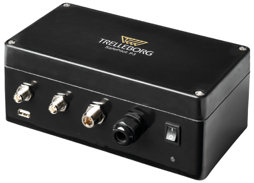
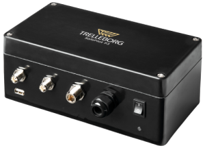
On Dec. 15, Trelleborg Marine and Infrastructure released SafePilot P3, a navigation system that meets Panama Canal Advisory (ACP) standards, which go into effect late next year for Neopanamax vessels. The navigation system provides real-time data on vessel positioning and movement in tight waterways.
SafePilot P3 operates on motion sensors and two GNSS antennas to measure the position and heading of vessels in three dimensions, minimizing time and difficulty associated with piloting procedures. SafePilot P3 has a backup battery to maintain functionality in the event of a power outage.
Image: Trelleborg SafePilot P3
This navigation system improves situational awareness while navigating waterways and ports globally, as it integrates with the ACP-approved Trelleborg SafeCaptain App. It also enhances communication between the captain, pilot, tug operators and canal personnel while vessels are transiting the canal and approaching the port.
SafePilot P3 is an addition to Trelleborg’s SafePilot portable navigation systems, which provide ports with real-time navigation information while giving pilots greater control and accuracy when approaching ports and performing intricate maneuvers.
By all accounts, it is getting worse. Hundreds of internet sites sell inexpensive devices to interfere with GPS and other GNSS signals. Estimates place the number of devices extant in the United States in the tens of thousands or more. Studies show accidental interference happens about ten times more often than deliberate jamming.
In January a high-power signal in the Denver area impacted GPS reception across 4,000 square miles of airspace. The source was located, and the signal terminated after 33 hours.
October saw a similar event near Dallas that lasted for 44 hours before it ended on its own. The source of that signal was never identified.
The United States spends more than $2 billion a year to operate, maintain, and refresh GPS. Its positioning, navigation, and timing (PNT) services underpin virtually every technology, every facet of the economy. Yet, as was dramatically demonstrated at least twice this year, the nation does not have the ability to quickly characterize, locate and mitigate even the most powerful jamming signals.
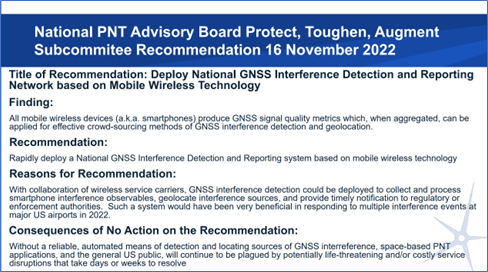
The group’s most recent recommendation is to implement a detection network based on crowdsourcing and smart phones. This would be done in collaboration with wireless service carriers.
Yet cooperation of wireless carriers, while helpful, may not be necessary, according to at least some experts.
Dr. Dennis Akos of the University of Colorado has developed an app for Android smart phones that enables devices to detect and automatically report interference with GPS and other GNSS signals. The app uses four detection methods based on location data already used by Android devices. These are comparing GNSS and network locations, checking the Android mock location flag, comparing the GNSS and Android system times, and observing the automatic gain control (AGC) and carrier-to-noise density (C/N0) signal metrics.
Commenting on Akos’ work, GNSS expert Logan Scott suggests that the U.S. government could use this new capability to establish the first phase of a national GPS/GNSS interference detection network with very little cost or effort.
“The US government provides managed phones to many government employees,” he said. “Having an app like Dennis’s operating on an opportunistic basis, [only when GPS is on in the phone] would give access to millions of phones as observers. Bottom line, the US could stand up a national observation network on an accelerated timeline, understand the nature of the threat, and avoid the embarrassments of [events such as those that occurred at] DIA [Denver International Airport] and DFW [Dallas Fort Worth airport]. And it would not cost much.”
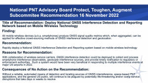
If an effective system of some sort is not implemented, American lives and property will be at continued and increasing risk. In the words of the Advisory Board recommendation:
Dr. Dennis Akos. Image from University of Colorado’s website.
“Without a reliable, automated means of detecting and locating sources of GNSS interference, space-based PNT applications, and the general U.S. public, will continue to be plagued by potentially life-threatening and/or costly service disruptions that take days or weeks to resolve.”
Spirent plans to host two seminars in early 2023 where experts will share PNT developments and provide training on Spirent’s products. Registration for the seminars is free and includes a two-week software license that can be downloaded to provide hands-on training.
Seminar training topics includes fundamentals of GPS/GNSS testing, how to create realistic testing scenarios, GPS/GNSS vulnerabilities like jamming and spoofing, vulnerability mitigation and more.
One session will be held in Huntsville, Alabama, March 8-9 and the other in Los Angeles, California, March 14-15. While registration is free, seats at both seminars are limited.
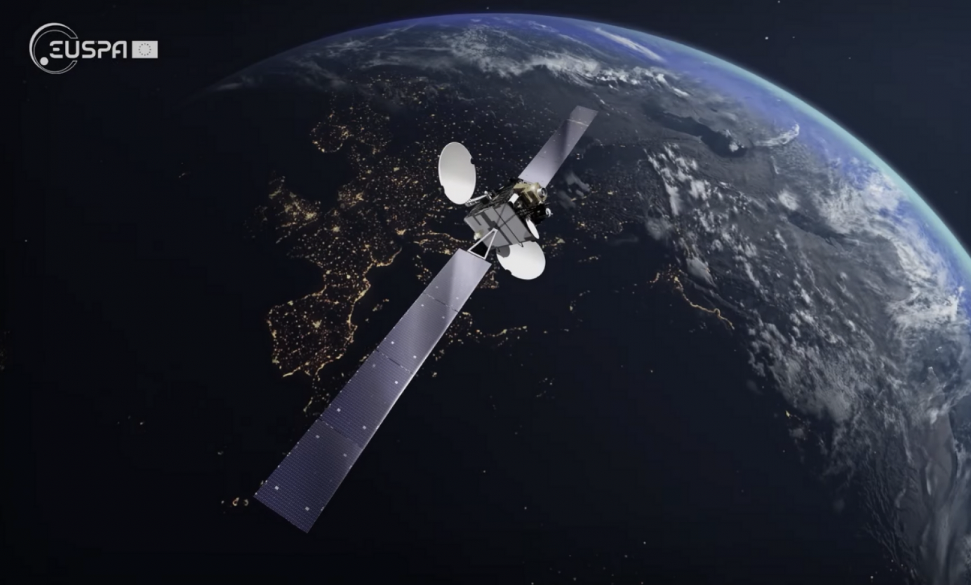
Europe’s regional satellite-based augmentation system (SBAS), EGNOS, has received upgrades to advance the reliability of GNSS positioning information, according to EUSPA.
Historically, EGNOS has provided safe, uninterrupted satellite navigation services to aviators, and some maritime, railroad, and land-based users in Europe. This system upgrade includes extending its service area, adding advanced functionalities, and reinforcing dual-frequency and multi-constellation services.
The EGNOS V242B system upgrade will expand services outside of its service area and enhance availability to users. Additionally, the upgrade ensures aviator access to lifesaving services such as Localizer Performance with Vertical Guidance (LPV)-200. The upgrade also includes more advanced data processing functions to cater to increased issues with peak solar activity and ionospheric phenomena that interfere with EGNOS signals and services.
Dual-frequency and multi-constellation services were also improved in the EGNOS upgrade. The improvements revamped EGNOS Version 2, and reinforced EGNOS services before launching EGNOS Version 3 (V3).
EGNOS delivers two frequencies and has amplified Galileo signals, hence creating a multi-constellation capability. When EGNOS V3 is launched, it will offer additional services and enhance protection against cyberattacks, further advancing EGNOS’ safety-critical applications across Europe.
SpirentCommunications has revealed its latest low-Earth-orbit (LEO) satellite solution software named SimORBIT, developed in partnership with space-borne receiver developer SpacePNT. The software is designed to aid developers in determining LEO orbits accurately for GNSS/PNT lab testing.
SimORBIT calculates LEO orbits as well as their environments and intricate characteristics to provide an accurate result to developers for testing. The software replicates LEO orbits so that simulations can provide the realistic environment of a LEO satellite, including gravitational and atmospheric impacts the satellite could encounter in space.
SimORBIT was created in partnership with spaceborne receiver developer SpacePNT. “Until now, PNT testing on LEO applications has been limited due to the lack of an integrated solution that could offer realistic LEO orbital data together with GNSS simulation capabilities,” explained Adam Price, Spirent’s vice president of PNT Simulation. “By working in close collaboration with SpacePNT, we have been able to develop the SimORBIT tool to bring a new level of accuracy and realism to LEO application testing by combining the simulation of precise LEO orbits and highly accurate GNSS signals.”
With Spirent’s release of SimORBIT, developers can create non-ICD signals via I/Q injection, or by the Spirent “Flex” feature, generating space-centered PNT signals to be developed in the lab as realistically as possible.
Position Partners has unveiled SmartSurveyor, which facilitates accurate, survey-grade aerial mapping and photogrammetry without the need for a connection between a camera shutter and a GNSS receiver.
The fully compact, handheld, aerial mapping survey rover is compatible with DJI Mavix 2 and 3 series and Phantom 4 Pro drones.
Image: Position Partners
The design is dissimilar to other drone mapping systems in that it works from a drone or smartphone and with two or more ground control points (GCPs) while using an ultra-matching technique.
Once data is captured by SmartSurveyor, all the photos and the GNSS file are uploaded to a PC and analyzed through the Agisoft UltraMatch workflow to confirm their accuracy before they are exported. Data can be managed in the cloud or on a local PC using software designed by MapSender.
Additionally, this mapping tool works in tandem with the AllDayRTK subscription GNSS network service so collected data can be uploaded to Tokara to remotely manage a project.
Achieving PNT resilience for critical infrastructure applications
GNSS are magic. They are. One dictionary defines magic as “a power that allows people (such as witches and wizards) to do impossible things by saying special words or performing special actions.” By this definition, we have all become witches and wizards, doing what previous generations would have deemed impossible.
This magic, however, can be affected by external forces that render it useless at best and, at worst, dangerous. Warnings about GNSS positioning, navigation and timing (PNT) service vulnerabilities have been raised for 25+ years. Numerous organizations have warned of the potential safety, security and economic impacts of GNSS interference. Still, like modern-day Cassandras, their warnings have been ignored, and sole use of PNT services that rely on space-based signals continues to expand.
“Magic services” are addictive and cannot be ignored. Yet, it is well past the time to merely admire the problem of GNSS interference — benefitting from magical GNSS services while ignoring existing and emerging threats and challenges. It is time to draw a line and implement resilient, complementary PNT solutions to support all critical infrastructure sectors and applications in the event of any GNSS disruption, due to jamming or spoofing or systemic causes. “Magic” is magical when it works. When it does not, first and foremost, it should “do no harm.”
Threats, Challenges and Needs
Presidential Policy Directive (PPD) 21, Critical Infrastructure Security and Resilience,issued in 2013, defines resilience as “the ability to prepare for and adapt to changing conditions and withstand and recover rapidly from disruptions.” It also notes that “resilience includes the ability to withstand and recover from deliberate attacks, accidents, or naturally occurring threats or incidents.”
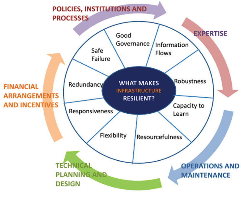
In 2016, the UK Department of International Development noted that “Resilience covers both ‘physical and societal systems” through four “R” principles: robustness, redundancy, resourcefulness and rapidity (see Figure 1).
Figure 1. Infrastructure resilience properties. (Image: UK Department of International Development)
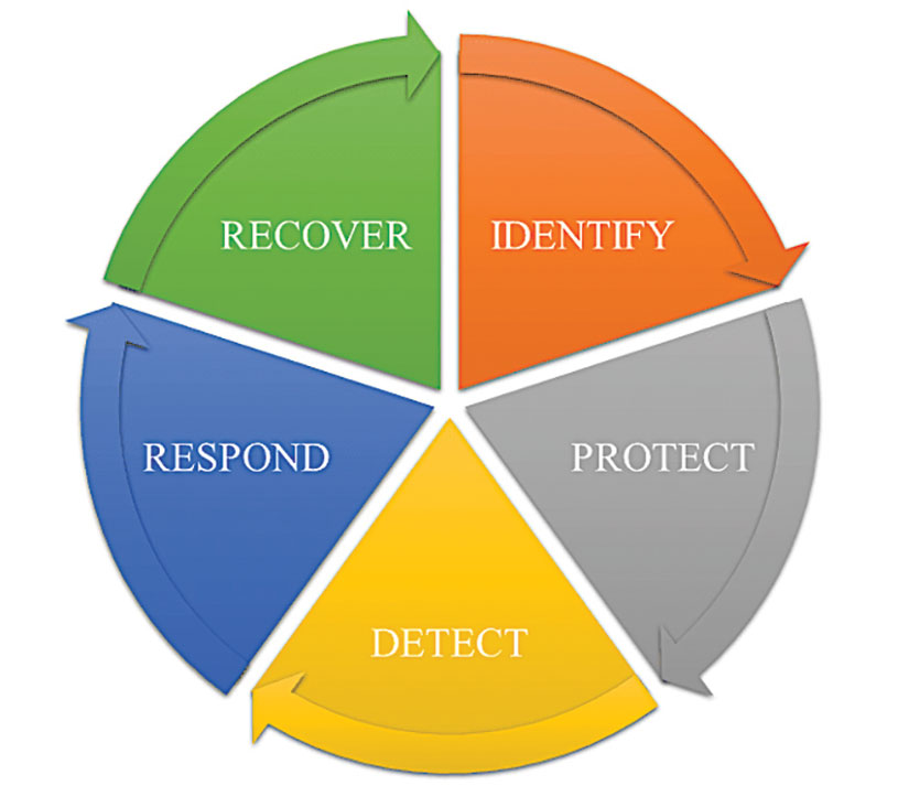
More recently, Andy Proctor (RethinkPNT) pointed out that “A resilient PNT system protects its critical capabilities (assets) from harm by using protective resilience techniques to passively resist or actively detect threats, respond to them, and recover from the harm they cause.”
Policies, processes, financial arrangements and incentives are also crucial to achieving resilience — and that has been, and remains, the problem. Lacking the emergence of strong leadership from our institutions, the ability to achieve actual resilience will continue to falter and admiration of the problem will continue.
Developing a resilient PNT system is always a balance of technical complexity and non-technical aspects, for example, costs. The key consideration for users must be the required performance metrics they need for their use-case(s) to ensure their resilience — including accuracy, availability, integrity, continuity and coverage. The one least understood and many times omitted is integrity — the level of trust a user/use-case needs to safely and securely use the PNT services. The ability to trust PNT services must always be a consideration for critical infrastructure applications.
Unfortunately, many users of critical infrastructure PNT do not know some of the PNT metrics they need to ensure safety and security. More troubling, there is no guidance as to what constitutes “significant economic impact” (see PPD 21) or acceptable economic loss — and over what period or range of use cases. This understanding will require analysis of their design, development and operational experiences, and working with PNT systems engineers to first derive these metrics and then drive the continuous improvements (see Figure 2) needed to achieve and retain truly complementary PNT capabilities. Without clear metrics and guidance, one cannot claim that any solution will meet any “required level of resilience.”
Figure 2. Resilient PNT lifecycle.
Supporting PNT Users
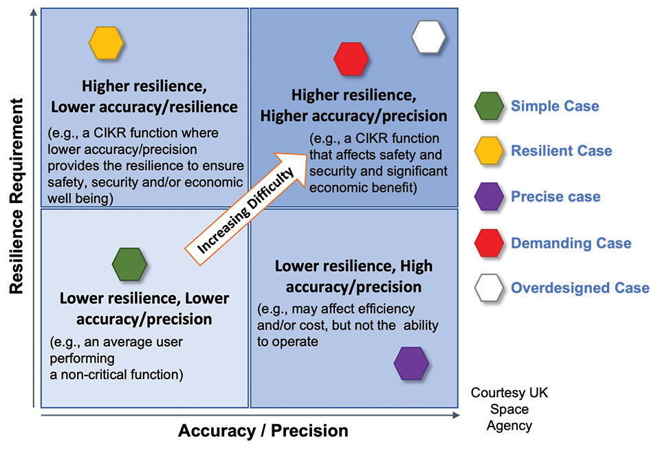
As with all systems engineering (SE) activities, PNT system resilience begins with identifying and documenting user needs based on their specific user stories/use cases. Figure 3 depicts different aspects of resilience that can be sought, depending on the unique use-case “demands.”
Figure 3. Resilience aspects. (Photo: UK Space Agency)
While the resilience needs of different use cases will differ, for any specific use case, a given “PNT solution” will either achieve the required/threshold level of resilience (based on the operational environment) or it will not. Some use cases may also require fail-safe or fail-soft capability and the ability to recover to known, trusted and usable states. Shouldn’t many, if not all critical sector use cases require this?
Equally important is the identification of risks and threats, as they are critical to understanding the challenges that the system must face while continuing to provide the necessary P, N and/or T service performance. It is also key to understand and document the system architecture and environment in which it must perform. With knowledge of a user’s needs, the threats, hazards and challenges they face, and the system architecture, the SE process can develop an understanding of the “gaps” that exist and of the levels of risk they impose on a critical infrastructure system’s functional, physical and operational performance. Understanding this, essential use-appropriate mitigations can be identified, or if need be, developed, and a resilient, solution-agnostic PNT requirement document created.
The Way Forward
The Critical Infrastructure Resilience Institute (CIRI), a U.S. Department of Homeland Security Center of Excellence, notes that “critical infrastructure systems are facing a myriad of challenges. Solutions must address the cyber, physical and human dimensions.” They keyed into four areas where critical infrastructure resilience activities should be directed: building the business case, information policy and regulation, developing new tools and technologies, fostering and educating the workforce.
These include the recognition that “policy and regulation have a powerful impact on market forces.” While the fact that “most U.S. infrastructure is owned and operated by the private sector” is a challenge, it should not be an excuse.
We must start immediately to re-establish strong SE practices, policies, and principles to help critical users understand their needs and determine the metrics required to ensure safety and “preclude significant economic impact.” Only then can we understand from a national perspective, the needed safety and security metrics and what constitutes significant economic impact, and then establish categories of solution-agnostic requirements. Lacking these clear resilience targets, detailed planning, and required resource commitments, the growing threats of PNT vulnerability will continue only to be admired, rather than be mitigated. Hope is not a strategy, but this systems engineer hopes that it does not take a truly catastrophic event to finally prompt much needed and long overdue actions.
Mitch Narins is the principal consultant/owner of Strategic Synergies LLC, a consultancy he formed following more than 40 years of U.S. government service. He is a Fellow of the Royal Institute of Navigation, a aenior member of the Institute of Electrical and Electronic Engineers, a member of the Institute of Navigation and head of its Washington, D.C., section, and a member of RTCA, RTCM, IEEE and SAE Standards Committees.
Registration is now open for the jointly sponsored Position Location and Navigation Symposium (PLANS) taking place April 24-27. PLANS is a biennial technical conference that occurs in the spring of odd-numbered years to provide an international forum to share the latest advances in navigation technology. The conference is sponsored by the IEEE’s Aerospace and Electronics Systems Society (AESS) and the Institute of Navigation (ION).
The PLANS conference takes place over four days, with the first day for hosting tutorials and three days dedicated to technical sessions.
The tutorials aim to provide attendees with the opportunity to learn about navigation technology from industry experts. A variety of tutorials are offered to serve the needs of both newcomers and those well versed in the field of navigation. This year’s tutorials will include a range of navigation subjects from core navigation fundamentals to in-depth classes about the latest technologies.
Technical sessions are offered over a three-day period, with four sessions running simultaneously each morning and afternoon. At the technical sessions scientists, researchers, and engineers from around the world present their latest work in the field of PNT. Technical session topics will include inertial sensing and technology; GNSS; integrated, collaborative and opportunistic navigation; and applications to automated, semi-autonomous and fully-autonomous systems.
To view the PLANS 2023 technical program and register for the event, visit ion.org/plans.
On Aug. 5, the National Geodetic Survey (NGS) stated it will be updating the NOAA CORS to be aligned with the latest International Terrestrial Reference frame, ITRF2020 (see below). As stated in the announcement, NGS will soon compute a third multi-year continuously operating reference station (CORS) solution, MYCS3.
The last multi-year CORS solution, MYCS2, was performed by NGS in 2019. I discussed the MYCS2 in my February 2019 and April 2019 columns. This new multi-year CORS solution will be important to the 2022 modernized National Spatial Reference System (NSRS), because NGS will establish a strict mathematical relationship between the 2022 NSRS frames and the ITRF2020 frame. This will allow direct access to the NSRS (NOAA Technical Report NOS NGS 67).
NGS Aligns National System to Global Reference Frame
August 5, 2022
The International Global Navigation Satellite System (GNSS) Service, which provides GNSS data products globally, recently released a new GNSS-only version of the International Terrestrial Reference Frame. This provides GNSS users access to the reference frame through coordinate functions for a global set of reference stations. In response, NGS will soon compute the multi-year Continuously Operating Reference Station (CORS) Solution 3, which will modernize the National Spatial Reference System. Aligning the National Spatial Reference System with the updated global reference frame will allow greater access for the global community of scientists, educators, and commercial users of location science.
For more information, contact: Phillip McFarland
As in the past, the multi-year CORS solution will mean that the NOAA CORS coordinates will be updated to be consistent with the latest International Terrestrial Reference Frame of 2020 (ITRF2020). The International GNSS Service provides information about its GNSS products and services. Readers can find information on the latest International Terrestrial Reference Frame 2020 here. This column will provide basic information on the ITRF2020. Please note: NGS stated that it will soon start computing the third multi-year CORS solution, but — as of October — all NOAA CORS coordinates are still based on MYCS2 and provide coordinates in ITRF2014 epoch 2010.00 and NAD 83 (2011, MA11, PA11) epoch 2010.00. As in the past, NGS will provide advance notice before publishing the results of its third multi-year CORS solution.
A document on the ITRF website stated the ITRF2020 is expected to be an improved solution compared to the previous solution, ITRF2014. It listed several innovations introduced in the ITRF2020 processing.
ITRF2020 is the new realization of the International Terrestrial Reference System. Following the procedure already used for previous ITRF solutions, the ITRF2020 uses as input data time series of station positions and Earth Orientation Parameters (EOPs) provided by the Technique Centers of the four space geodetic techniques (VLBI, SLR, GNSS and DORIS), as well as local ties at colocation sites. Based on completely reprocessed solutions of the four techniques, the ITRF2020 is expected to be an improved solution compared to ITF2014. A number of innovations were introduced in the ITRF2020 processing, including:
The time series of the four techniques were stacked all together, adding local ties and equating station velocities and seasonal signals at colocation sites;
Annual and semi-annual terms were estimated for stations of the 4 techniques with sufficient time spans;
Post-Seismic Deformation (PSD) models for stations subject to major earthquakes were determined by fitting GNSS/IGS data. The PSD models were then applied to the 3 other technique time series at earthquake colocation sites.
The box below provides a good summary of the International Reference Frame and why it’s important to the scientific community as well as the surveying and mapping community. Readers can download the article from the June 2022 International GNSS Service Issue 4 newsletter. Users also can sign up to receive notices and newsletters from the International GNSS Service.
What is the current rate of sea level rise in different regions of the globe? How does our Earth deform under the effect of plate tectonics, seismic phenomena, or the melting of ice caps? How the Earth’s center of mass is varying? How to determine the position of a point on the surface of a constantly deforming Earth and compare it to positions estimated decades apart? The answers to these fundamental questions for understanding the dynamics of our planet require the availability of a global, long-term stable terrestrial reference frame, but preferably a standard reference so to ensure interoperability and consistency of various measurements collected by sensors on the ground, or via artificial satellites. The International Terrestrial Reference Frame (ITRF) is the standard reference recommended by a number of international scientific organizations, including the International Union of Geodesy and Geophysics (IUGG) and the International Association of Geodesy (IAG) for earth science, satellite navigation and operational geodesy applications. The ITRF is an international effort that is built on the investments of space and mapping agencies, universities and research groups in operating geodetic observatories, archiving and analyzing the collected geodetic observations to derive not only the ITRF, but also critical geodetic products for science and society.
The ITRF integrates and unifies technique-specific reference frames provided by the four IAG’s international services of space geodetic technique (DORIS/IDS, GNSS/IGS, SLR/ILRS, VLBI/ IVS). It is supplied to the users in the form of temporal coordinates of more than 1500 stations, Earth Orientation Parameters, as well as parametric functions describing nonlinear station motions: seasonal signals due to mainly loading effects and post-seismic deformations for sites subject to major earthquakes. It is necessary to regularly update the ITRF (approximately every 5 years) in order to benefit from continuous observations so to improve its accuracy, considering station position temporal variations due to geophysical phenomena.
The ITRF is maintained by a research group at IGN-France and IPGP (Institut de Physique de Globe de Paris), and whose new release called ITRF2020 was published on April 15 and accessible here: https://itrf.ign.fr/en/solutions/ITRF2020. The ITRF2020 brings significant improvements compared to previous achievements: it confirms the estimate of the position of the center of mass of the Earth as it was determined in 2016, but also provides its seasonal variations; it improves the accuracy of the scale of the frame at the millimeter level, which represents a gain in precision of a factor of 8 on the measurement of the size of the Earth (compared to that determined in 2016); it provides a precise quantification of co- and post-seismic displacements caused by devastating earthquakes, such as that of Sumatra in 2004, Chile in 2010 and Japan in 2011. The IAG Services rely on the ITRF to align their geodetic products to it, and therefore disseminate it widely among the various users. In particular, using the IGS products, such as the orbits, allows a universal access in space and time to the ITRF.
As stated in the article by Zuheir Altamimi, ITRF2020 involves IAG’s international services of four space geodetic techniques: DORIS/IDS, GNSS/IGS, SLR/ILRS, VLBI/ IVS. Computing an International Terrestrial Frame is very complex and requires analyses of difference types of geodetic and geophysical data. It is beyond the scope of this column, but online is more detailed technical information.
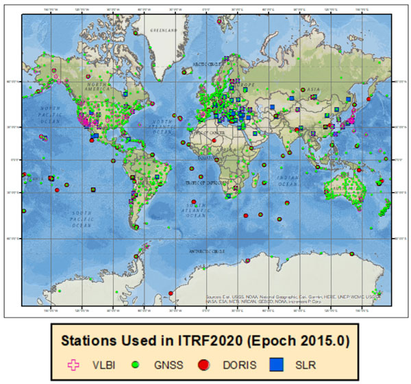
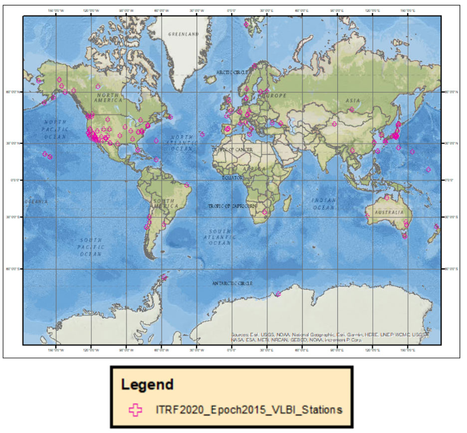
For this column, I downloaded the station lists from the four space geodetic techniques and provided a few plots that depict the location and velocities of these sites. The box below depicts the location of the space geodetic techniques around the world. As indicated in the plot, some locations have more than one technique collocated at the same site.
Plot of the Four Different Space Geodetic Techniques
Image: Dave Zilkoski
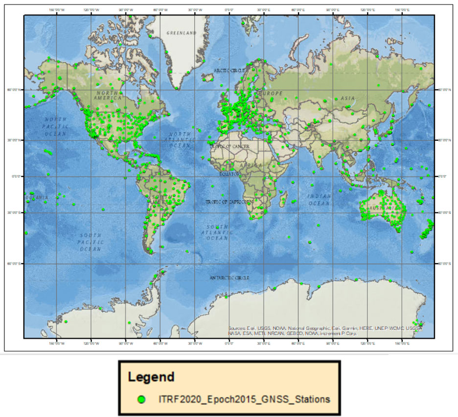
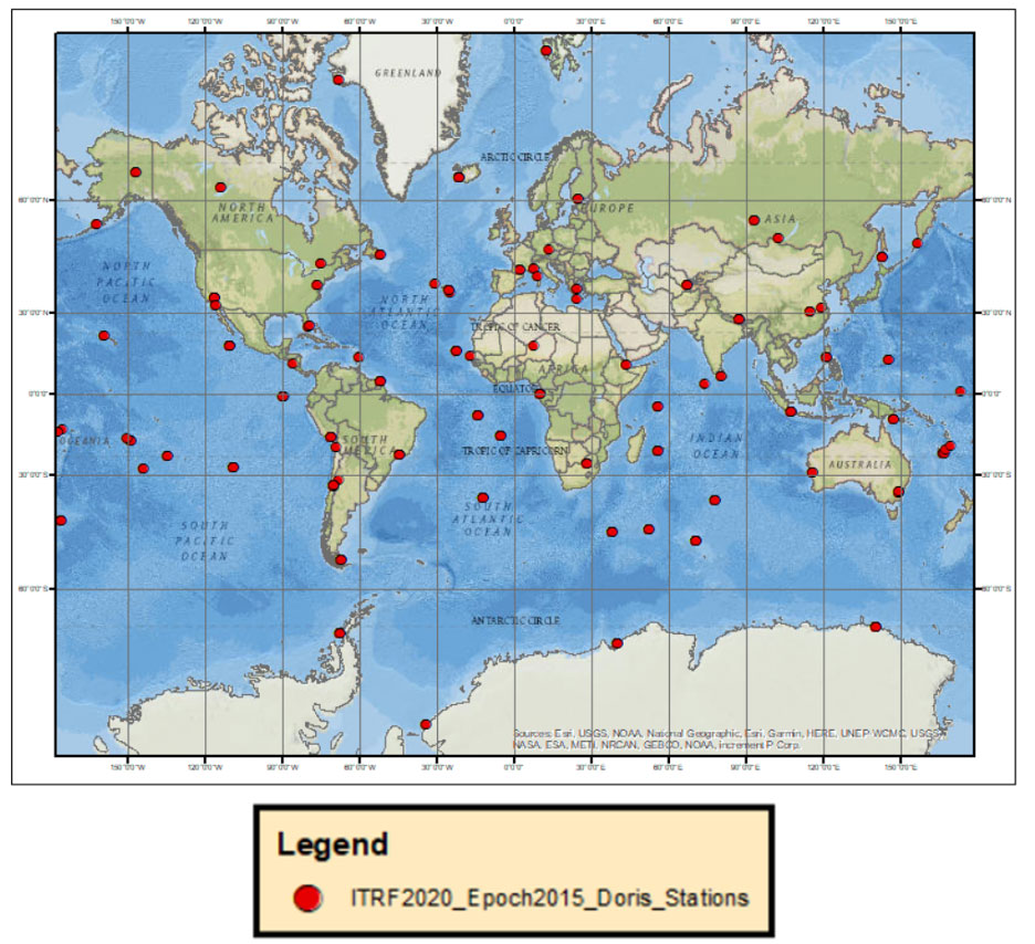
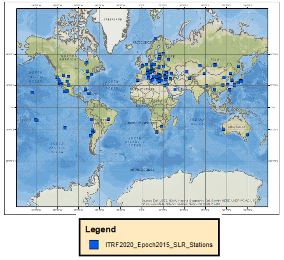
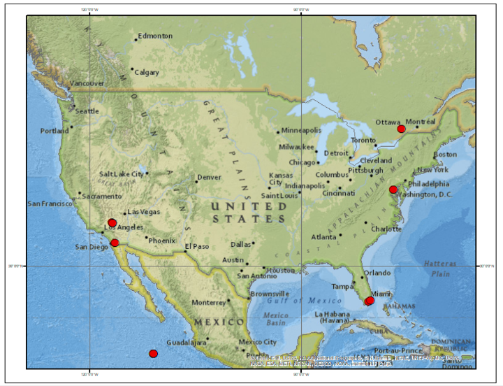
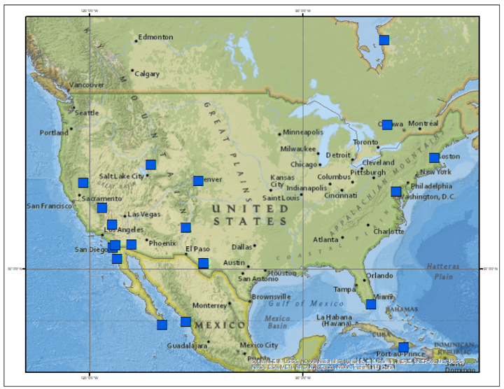
The following plots depict the locations using each space geodetic techniques: GNSS sites, DORIS sites, SLR sites and VLBI sites.
Plot of GNSS Sites
Image: Dave Zilkoski
Plot of DORIS Sites
Image: Dave Zilkoski
Plot of SLR Sites
Image: Dave Zilkoski
Plot of VLBI Sites
Image: Dave Zilkoski
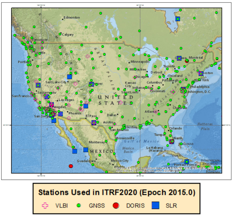
The box below shows the location of the techniques in the conterminous United States.
Plot of the Four Different Space Geodetic Techniques in the CONUS
Image: Dave Zilkoski
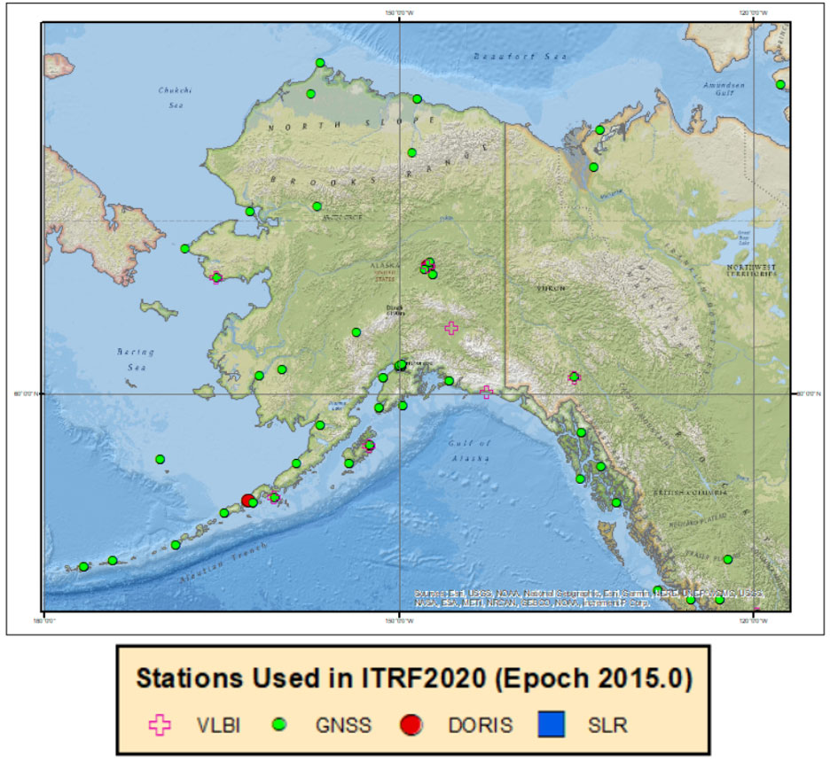
The plot below depicts the sites in the state of Alaska.
Plot of the Four Different Space Geodetic Techniques in the Alaska
Image: Dave Zilkoski
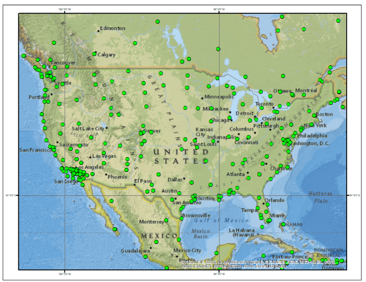
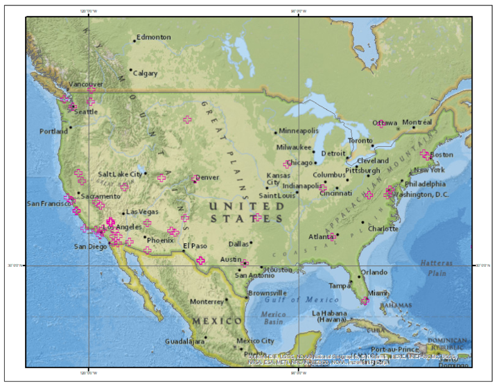
The images below depict each of the four space geodetic techniques in the conterminous United States.
Plots of the Space Geodetic Techniques by Technique in the CONUS
Plot of GNSS Sites in CONUS Image: Dave ZilkoskiPlot of DORIS Sites in CONUS (Image: Dave Zilkoski)Plot of SLR Sites in CONUS (Image: Dave Zilkoski)Plot of VLBI Sites in CONUS (Image: Dave Zilkoski)
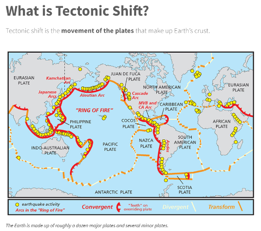
Altamimi’s article on the ITRF2020 stated it is “necessary to regularly update the ITRF (approximately every 5 years) to account for station position temporal variations due to geophysical phenomena.” My February 2022 column discussed the tectonic plates and why is it necessary to account for movement in a geodetic reference frame. As I stated then, coordinates basically change because the Earth’s surface is moving due to the movement of major tectonic plates. See the box titled “What is Tectonic Shift?” for information about why it is called plate movement or tectonic shift. The world’s geodesists understand this and are attempting to manage the changing coordinates by providing a time-dependent component of the international terrestrial reference frame.
Image: National Ocean Service websiteImage: National Ocean Service website
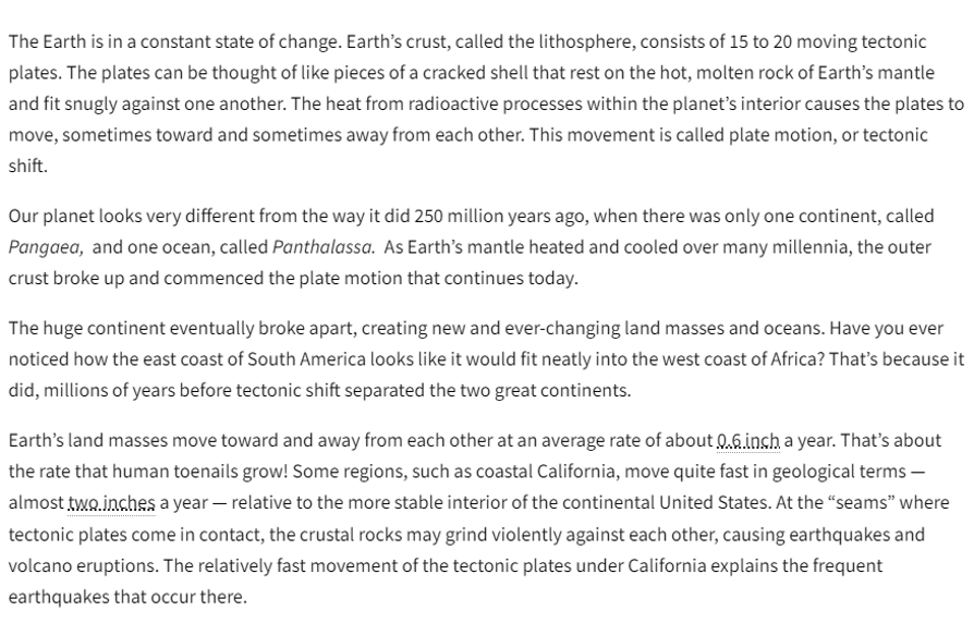
The box below depicts the horizontal velocity based on the ITRF2020 velocities (downloaded on 08/12/2022).
Plot of the Horizontal Velocity Vectors based on the ITRF2020 Velocities
Image: Dave Zilkoski
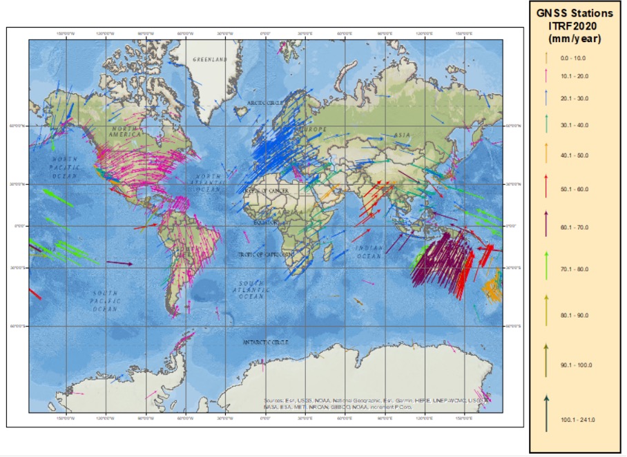
The box below depicts the horizontal velocities in the North America. These vectors look very similar to the velocities reported in my February 2022 column.
Plot of the Horizontal Velocity Vectors in North America based on the ITRF2020 Velocities
Image: Dave Zilkoski
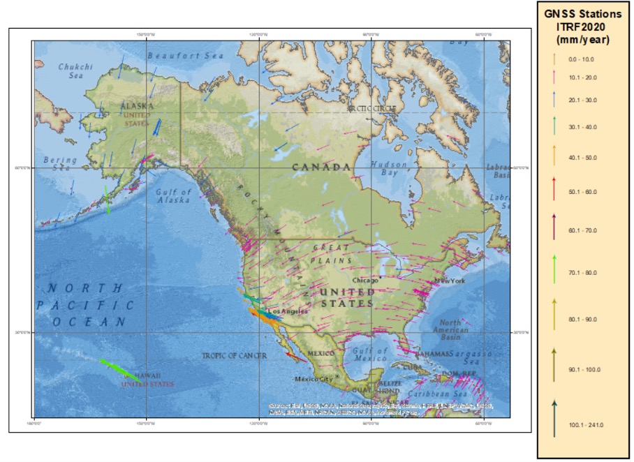
For a comparison to North America vectors, the box below depicts the velocity vectors in Europe.
Plot of the Horizontal Velocity Vectors in Europe based on the ITRF2020 Velocities
Image: Dave Zilkoski
They are similar in magnitude, but not in direction. Once again, looking at the map of tectonic plates, North America is located mostly on the North American plate and Europe is on the Eurasian plate.
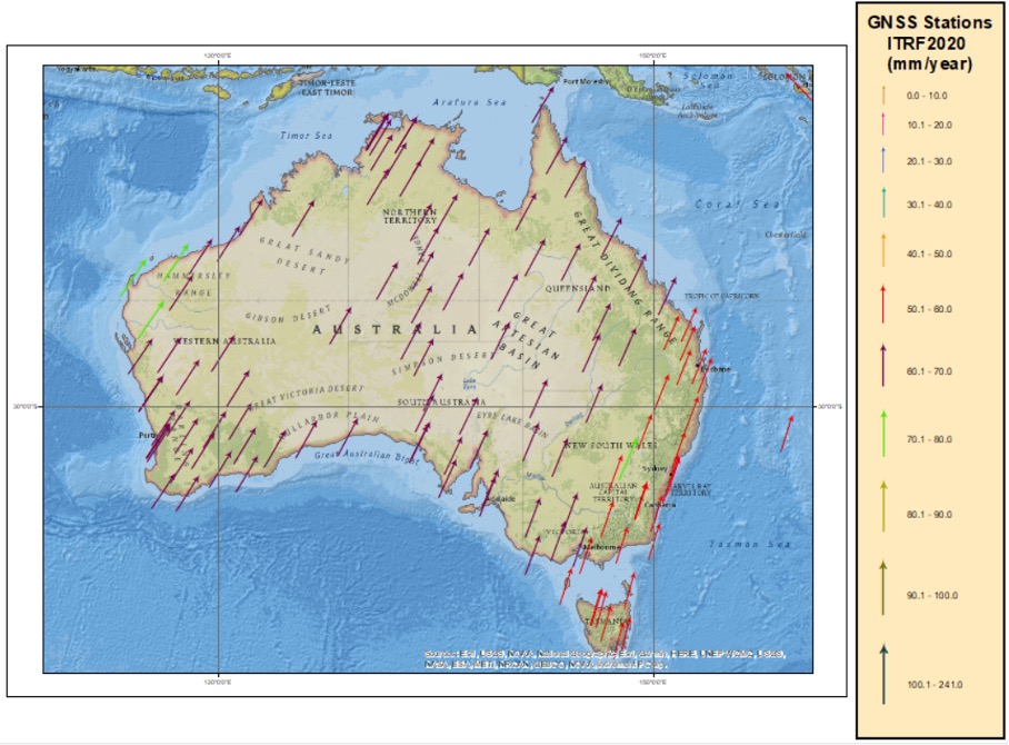
Australia is on the Indo-Australian plate and has some fairly large horizontal velocities vectors. See the box below.
Plot of the Horizontal Velocity Vectors in Australia based on the ITRF2020 Velocities
Image: Dave Zilkoski
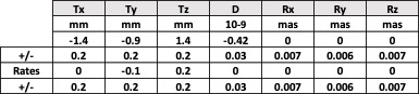
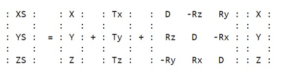
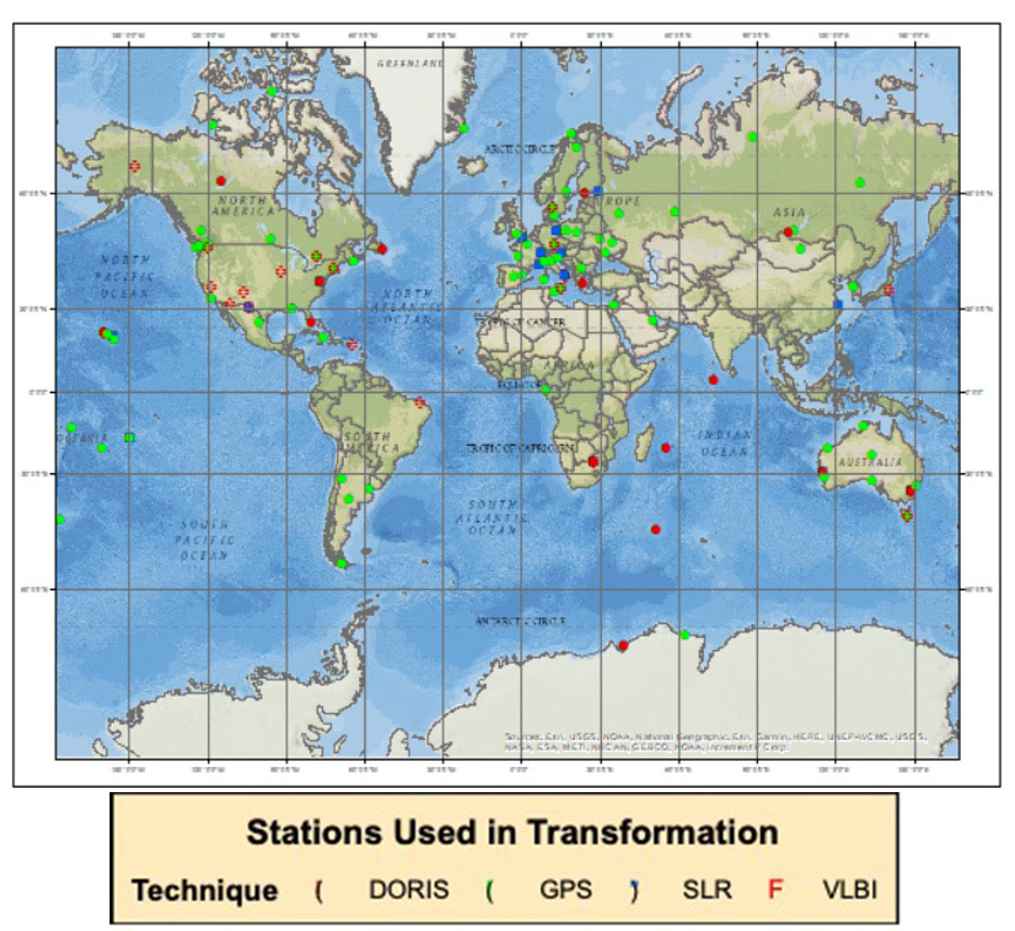
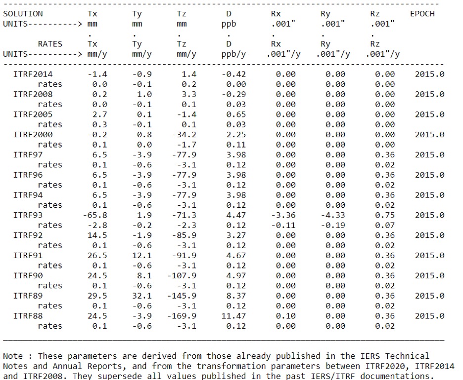
So, what’s the difference between ITRF2014 and the new ITRF2020? The box below provides the 14 transformation parameters from ITRF2020 to ITRF2014. These transformation parameters have been estimated using 131 stations located at 105 sites. See the box “Plot of the Stations used in the Transformation Parameters from ITRF2020 to ITRF2014” for the location of these stations. Notice that the translation values in X,Y,Z are very small (<1.5 mm) between the two reference frames.
Transformation Parameters from ITRF2020 to ITRF2014
X,Y,Z are the coordinates in ITRF2020, and XS,YS,ZS are the coordinates in ITRF2014.
Plot of the Stations used in the Transformation Parameters from ITRF2020 to ITRF2014
Image: Dave Zilkoski
The transformation parameters from ITRF2020 and past ITRFs are provided in the table below. As indicated in the table, most of the changes in X,Y and Z are very small since ITRF2005.
Transformation Parameters from ITRF2020 to Past ITRFs
As previously stated, the third multi-year CORS solution will be important to the new 2022 modernized National Spatial Reference System (NSRS) because NGS will establish a strict mathematical relationship between the 2022 NSRS frames and the ITRF2020 frame. This will allow direct access to the NSRS, according to NOAA Technical Report NOS NGS 67. Again, there will not be any changes to NGS’s NOAA CORS coordinates due to ITRF2020 until NGS completes its third multi-year CORS solution.
Users can receive emails about the latest NGS News by signing up for NGS’s newsletters. These notices will highlight the release of new products, updates to existing services, progress reports for major projects, information about upcoming NGS-sponsored events, and job opportunities at NGS.
Jackson Labs Technologies PNT-6200 Series, an STL-based time and frequency reference system installed in a 5G application. Photo: Satelles
We discussed Satellite Time and Location (STL) services and complementary PNT with Michael O’Connor, CEO at Satelles.
What is the problem with GPS/GNSS that Satelles aims to solve?
GPS and GNSS are amazing. We designed Satellite Time and Location (STL), the service that we offer, to complement those capabilities. We have focused on three unique aspects in the areas where GPS could use complementary service. First, we provide a fully independent backup. We all know that things can happen, so we aim to provide an independent source of position navigation, and timing (PNT). Second, we focused the high-power aspect of STL to enable us to reach indoors and other places where GPS does not reach. Because STL comes from low Earth orbit (LEO) satellites, the signals are naturally at a higher power.
We also focused on improving the indoor penetration capability by enhancing the signal design and doing some other things. Third, we use modern cryptographic techniques to ensure the security and resilience of the system, specifically to intentional misdirection attacks. If you can ensure that the signal is coming from the satellite and not from a third party you can have a more secure and resilient solution.
To what extent can you replace GPS during an extended outage?
We have never considered LEO PNT as a replacement for MEO (medium Earth orbit) GNSS. GNSS are the primary domain of PNT but there are applications that have additional needs. The more independence you can get, the fewer the common modes of failure, if you can at least have some survivability in the absence of GNSS. That’s one of the services we can offer. It is probably not the most important thing to our customers, honestly. The service we offer is similar to GPS and GNSS in that we have a space segment (the satellites), a ground segment, and a user segment. We have space vehicles, user equipment, and ground infrastructure that supports the space infrastructure.
What’s interesting about the way we work with the Iridium satellite constellation is that the satellites themselves include inter-satellite links. That provides a lot of resilience to ground-based events. The satellites themselves have a time transfer capability between them. So, we don’t require a direct connection to every satellite to propagate a time throughout the network. That’s one unique aspect we can take advantage of with this particular network, Iridium, which is pretty amazing.
Additionally, we have multiple ground infrastructure and monitoring sites and multiple sources of time at those ground monitoring and control stations. For example, some of them rely on GNSS combined with atomic clocks as their master timing source but we also have one installed at the National Institute of Standards and Technology facility in Boulder, Colorado. So, we have multiple primary time sources that we can integrate into our filtering across the network. That, combined, with satellite links, allows us to maintain time for substantial periods independent of GNSS.
How do you define “complementary PNT” and how does Satelles fit in that mix?
Several applications have additional needs beyond what GNSS offer. There are many technologies that can come to bear on that. There’s the LEO satellite base, which is where Satelles fits in, but there are also local and wide-area terrestrial radio navigation sources, network-based time transfer, signals of opportunity, and so on. They all have something important to offer, depending on the application. Satelles’ LEO satellite solution is available today, has global coverage, and is relatively affordable. It leverages the capital investments that have been made to launch the satellites to provide this service globally. The industry is working together to make sure that an awareness of these capabilities is propagated throughout the industries that we serve.
Besides the orbit height, which requires many more satellites, how does your system differ from GNSS?
We do not consider LEO PNT as something that might replace MEO PNT. The fundamental difference is being in lower Earth orbit, which results in a higher received power. That is what allows us to penetrate, just based on the 1/r2 losses. The measurable Doppler signatures give additional observables for PNT calculations, and higher satellite dynamics that can help with multipath. This service relies on many of the same physics and geometry as GPS. We measure the time of arrival of a very similar signal. The signals from the Iridium satellites are even in the L band. Very often we’re using a GPS chip that’s been reprogrammed to track and utilize our service as well as GPS or instead of GPS.
If I explained how GPS works to, say, a high school science class, how much of that basic explanation—about trilateration, spread spectrum, etc.—would also apply to your system?
It’s fundamentally the same. It relies on a lot of the same physics and geometry. We measure the time of arrival of a very similar signal. The signals from the Iridium satellites are even in the L band. Very often we’re using a GPS chip that’s been reprogrammed to track and utilize our service as well as GPS or instead of GPS. There are subtle differences—for example, a lower Earth orbit is faster—but it is very similar.
How would GPS user equipment have to be modified to make use of your service?
We don’t think of STL as something where we are modifying GPS user equipment. Rather, we think about what must be done in an end-user application to meet their needs. For example, one of our partners, Orolia, has a GNSS + STL secure synchronization product that we have delivered to customers in data centers and major stock exchanges around the world. Those are operational and in service. They integrate through standard interfaces, such as PPS or PTP, depending on the type of equipment to which they are connecting.
Ultimately, we don’t think of it is as replacing GPS user equipment. Rather, where a user has a need for PNT, they’re opting for this GNSS + STL solution because they have an indoor need, such as a data center, or they have a need for resilience in the case of a stock exchange.
Another example is Jackson Labs. The Jackson Labs 2600 is also a GNSS + STL solution that generally is integrating with existing 5g. It has a specialized transcoder interface that can work with any existing GNSS-type equipment. In some cases, we’ve taken a chip that was originally designed for GPS and modified its firmware.
Who are the earliest adopters?
Satelles’ LEO satellite solution is available today, has global coverage, and is relatively affordable. It leverages the capital investments that have been made to launch the satellites to provide this service globally. Data centers, stock exchanges and cell phone providers are implementing these capabilities today. The major wireless operators are seeing that more and more of the 5G infrastructure they roll out is going indoors, where GPS doesn’t reach. We provide a solution that integrates with their existing solutions and can provide reliable timing capabilities.
If your solution can survive on its own, why does it need GNSS at all?
In some cases, the user is not using GNSS at all. The product itself has a GNSS capability. User equipment is very affordable and the service is taxpayer-funded. In many cases, especially for indoor installations, the equipment that is installed is capable of tracking GNSS and STL signals, but often it relies on the STL signal itself for timing.
How do you predict STL spreading through various applications and industries?
We have our hands full with the markets we’re going after now, but there are certainly going to be other markets in which the customers will recognize that they have a critical need to implement a backup solution.
In the long run, could LEO satellites replace MEO ones for GNSS?
Sometimes there have been misperceptions in the industry. I’ve never considered that LEO PNT satellites might replace MEO ones. There are excellent reasons why Brad Parkinson, Jim Spilker, Gaylord Green and others decided almost 50 years ago to put GPS in MEO. Those physics haven’t changed. You can cover a large portion of Earth with each satellite. LEO will not replace MEO, but it has unique characteristics that make it a great complement to the GNSS MEO solutions.
Do you have any additional comments about complementary PNT?
It’s good to see that the federal government is encouraging the adoption of complementary PNT, which they often call “GPS backup.” It is encouraging to see the amount of activity on this issue that’s been going in Washington over the last couple of years. Although our company is very focused on delivering a LEO-based PNT service, which has several advantages for customers that need a global capability, many technologies can play an important role in those solutions.
The U.S. Department of Transportation did a fantastic job of looking at several of those technologies across those different categories. The European Union has also had a similar activity recently. Some reports will be coming out soon about that. It is very important that the government understands that this is an important issue for our society and encourages industry to adopt these solutions and is even starting to make some investments toward that. That includes executive order 13905 and some recent funding increases by Congress.
All of that has been very important and positive, as has modifying some of the legislation to be more inclusive of multiple technologies, such as removing the words “land-based” from the National Timing, Resilience, and Security Act this year.
I am involved in an industry consortium, the Open PNT Industry Alliance, with several other companies whose CEOs are in alignment that there is no single answer. Having a thriving ecosystem of technologies and companies trying to solve this important problem is incredibly important and it’s exciting to see.
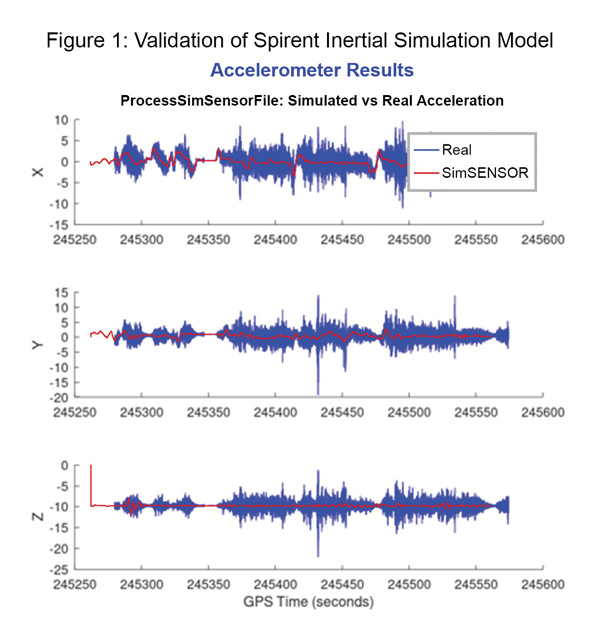
Data shows how successful baseline validation testing of Spirent’s inertial simulation model as compared to real world inertial system performance. Photo: Spirent Federal Systems
We discussed complementary PNT with Roger Hart, head of engineering and Jeff Martin, head of sales at Spirent Federal.
What are some of the most promising approaches to complementary PNT sources and how does simulation technology help?
Roger Hart: The vulnerabilities of GNSS have been recognized. Legacy GNSS are all operating on pretty much the same frequencies and power levels, so, they have some significant common vulnerabilities. There is great interest in finding ways to complement or even replace those capabilities.
Dead reckoning, magnetic and inertial systems have been around for a long time. There are emerging markets to make use of alternative radio frequencies for navigation. In some cases, we are piggybacking on communications signals and deriving PNT from them. In other cases, we are using new PNT signals. A couple that we’ve been focusing on are the alternative navigation systems.
They may be using different orbits, different frequencies, different encoding schemes that set them apart from the legacy GNSS systems, so that, used together, they provide greater resiliency and even stand alone when one or the other system may be affected by interference.
Not to be forgotten is inertial navigation. It’s been around for a long time and is still a standard of navigation. Together with GNSS, it makes it a terrific navigation system. It almost defines complementarity because where GPS is vulnerable inertial can fill in the gaps and where inertial drifts GPS does not. So, paired, they make a very strong system.
At Spirent, we’ve been working with customers to provide a variety of options for both those alternative navigation systems and inertial. Both are a very active field of development and we’re keeping abreast of that.
Jeff Martin: Some good points, Roger. This is something we’ve been engaged in for quite a long time. Since we provide test equipment to the community, it’s critical that we understand what they’re worried about, what the vulnerabilities are. It keeps things exciting, it keeps us on our toes and looking ahead to what’s coming.
What are some of the remaining challenges of integrating GNSS receivers with inertial sensors and, again, how does simulation technology help with that?
Hart: Inertial works by integrating sensor measurements that come in. Therefore, any errors that are present just accumulate over time and can corrupt your navigation solution. So, there’s a strong focus on updating error models and on translating them so that everyday users can use them and get real-life-type performance out of them.
There’s a tendency to think of integrating GPS-INS as putting everything together in one box. There are packages that do that. However, the push now is to go to more distributed systems that are integrated but not packaged in the same box. One example is the all-source positioning and navigation standard that is being developed by the Department of Defense. It will allow you to swap one sensor for another as long as they adhere to the standard. That information all goes back to a sensor fusion engine.
Martin: We have known GNSS simulators well for about four decades. We have been playing in the inertial sandbox for at least a couple of decades as well. This has given us the opportunity to build relationships with the with the key manufacturers and designers of inertial systems. Those relationships have been expanding well beyond inertial to many other sensors and systems that are now coming online. It’s been exciting.
Much work is going into using low Earth orbit satellites for PNT—whether piggybacking on the Iridium satellites or launching new ones. How does simulation help with that?
Hart: It certainly helps with the development of the receivers. The groups that are using these alternative RF and LEO or MEO systems need simulation as they develop the receivers. It gives you the ability to try things certainly before you launch them. At this conference there is considerable interest in making things reprogrammable. We have the NTS-3 satellite, which will be running experiments for different waveforms that can be generated. Even M-code is a step in the direction of giving more flexibility to the signal. It has a lot more flexible cryptography and signal generation than the legacy system with the C/A and P/Y codes.
Our simulation platforms are software based, so we can generate and receive data that can be useful for developing software-defined receivers. It gives you the opportunity to try different waveforms. We have already delivered a satellite-based alternative navigation system simulator. Now, we can build on that one to help the other Leo constellations as they come forward.
Martin: Roger put it well. This is where things get fun. People are concerned with PNT vulnerabilities, so we’re seeing these alternative navigation solutions coming forward. Spirent has done a good job over its nearly 40 years of existence of manufacturing and designing its own hardware and software. It has given us the opportunity to respond quickly. These things are coming fast. People need solutions quickly. We have some solutions already and the platform that we have created gives us the flexibility to develop more. We’re seeing more and more ideas come to fruition and people need to test them. So, this is where it gets fun. We’re excited.
Much work has gone into addressing the enduring challenge of urban canyons. How does simulation technology help?
Hart: Urban canyons are the worst nightmare for GNSS signals. If you’re surrounded by tall buildings, signals are blocked. You may have few or even no satellites in a direct line of sight and many multipath reflections. So, diminished and corrupted signals are available to you. Of course, the more GNSS satellites you have, the better chance you have of getting good signals. But complementing that are radar and vision systems. Those are the ones that will stand out, particularly the vision systems that can read the street signs, see where the curb is, look for parked cars. All those kinds of things will help fill in when you have poor GNSS coverage.
You can observe what’s going on in the environment and simulate it. You can also use our forecasting tool to look ahead.
Martin: This is where things get exciting, isn’t it? In these terrible environments where GNSS is contested—whether it’s an urban environment or one with intentional jamming—there is a lot we can do to help our industry. When this happens in real life, it’s bad news. But when you create that scary situation in the controlled environment of a laboratory, it is great. You can pick things apart and see where you need to improve. I get excited about it. It’s probably the geek in me. It gives us and our partners a lot to look forward to.
How does simulation technology help with sensor fusion?
Hart: It definitely helps you put all the pieces together. You can’t know how your system will work by individually testing each piece. System is the key word here. Simulation enables you to generate the signals and bring them together into a sensor fusion engine. You can test different algorithms. It’s certainly much cheaper and quicker than trying to build this into a product and then test it. Over the decades, simulation has proved itself as a very valuable way in both basic development and integrating the final product.
Martin: That system-wide fusion is where the magic happens.
It sounds like simulation technology—and Spirent Federal in particular—are very much at the center of a lot of the current developments and discussions about complementary PNT. Do you have any final comments?
Hart: As Jeff said, it’s an exciting time. There are many things going on—new technologies, new ways of communicating. It’s a busy time and a bit of a scramble sometimes to keep up with all the new things that are coming.
Martin: People look to Spirent to be their testing resource and it puts us right in the middle of it.
A roundup of recent products in the GNSS and inertial positioning industry from the April 2022 issue of GPS World magazine.
OEM
GNSS+5G Antenna
9-in-one combination antenna with dual-band GNSS
Photo: Taoglas
The Taoglas MA990 Guardian antenna is a 9-in-1 combination antenna with dual-band GNSS (L1/L2) and globally supported cellular (5G/4G). It has been designed to support emerging market demand for modules that cover specific 5G/4G bands. Two of its eight cellular MIMO antennas cover from 600 Mhz to 6,000 MHz, while another two are optimized for 3,000 MHz to 6,000 MHz to cover high-band 5G and C-band/CBRS applications. The customizable antenna is designed to operate on all global carrier networks and is future-proofed to work with the latest 5G routers on the market. Housed in a low-profile, robust, IP67-rated waterproof, adhesive-mount external enclosure, the MA990 is designed for space-constrained, mission-critical applications, including asset and vehicle tracking, first-responder vehicles and high-definition video sources such as surveillance cameras.
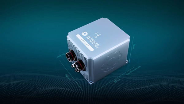
The Boreas fiber-optic-gyroscope inertial navigation system (INS) is an ultra-high accuracy, strategic-grade INS offering a reduction in size, weight, power and cost. It is based on Advanced Navigation’s new digital fiber-optic gyroscope (DFOG) technology. The Boreas is targeted at applications requiring always-available, ultra-high accuracy orientation and navigation including marine, surveying, subsea, aerospace, robotics and space. It delivers strategic-grade bias stability of 0.001 deg/hr. This allows it to achieve ultra-high roll/pitch accuracy of 0.005 degrees and heading accuracy of 0.006 degrees. The Boreas allows for full independence from GPS with dead-reckoning accuracy of 0.01% of the distance traveled with an odometer or Doppler velocity log. In addition, the Boreas features ultra-fast gyro compassing, taking only two minutes to acquire heading in both stationary environments or on the move. Gyro compassing allows the system to determine a highly accurate heading of 0.01 degrees secant latitude without relying on magnetic heading or GPS.
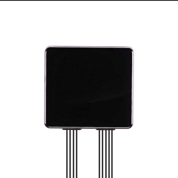
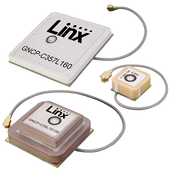
Seven new GNSS active ceramic-patch antennas support global GNSS applications including GPS, Galileo, GLONASS, BeiDou, NavIC and QZSS systems in the L1/E1/B1, L2/E5/B2B, and L5/E5/B2A bands. Each antenna integrates a high-gain low-noise amplifier (LNA) and right-hand circular polarization (RHCP) to provide a high-performance solution for GNSS signal reception. Each active GNSS antenna has either a 60-mm or 100-mm coaxial cable terminated in a MHF1/U.FL-type plug (female socket) connector. They also meet the need for multi-band L1/L2, L1/L5, and L1/L2/L5 GNSS offerings.
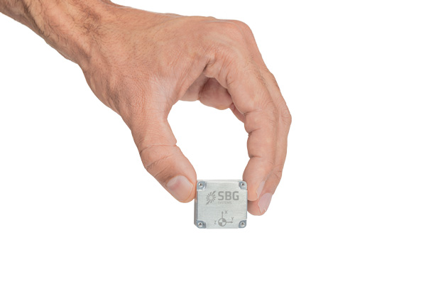
The Pulse-40 inertial measurement unit (IMU) is a tactical-grade IMU designed for high performance in harsh conditions but miniaturized for applications where precision and robustness matter in all conditions. Use cases include warfare systems, satellite communications, robotics, lidar devices, gimbals, cameras and inertial navigation systems (INS). The Pulse-40 IMU provides six degrees of freedom. It integrates micro-electromechanical (MEMS) three-axes accelerometers and gyroscopes in a unique redundant design that allows the device size to shrink while pushing performance to its maximum. Among the performance specifications, the Pulse-40 features excellent gyro and accelerometer bias instability of 0.8°/h and 6 µg respectively, enabling long dead-reckoning and maintaining excellent heading performance. With sensors featuring extremely low vibration rectification error (VRE), the Pulse-40 can sustain high vibration environments, up to 10 g root-mean-squared. An embedded continuous built-in-test ensures data reliability during operation, a key parameter for critical applications. Features include 12 grams, 0.3W power consumption; ultra-low noise gyro (0.08°/√h) and excellent gyro bias instability (0.8°/h); high-precision accelerometers (6 µg); MIL-STD 810-qualified for shocks and vibrations; high bandwidth (480 Hz) and high data rate (2 KHz); highly tested and calibrated from –40° C to 85° C; and no export restrictions.
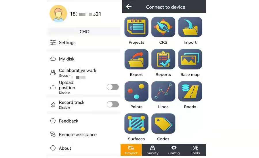
Adds online services for field surveying and mapping
Photo: CHC Navigation
LandStar version 7.3.7 adds cloud-based services and remote support features to simplify surveyors’ daily tasks. Online data storage and file sharing greatly facilitates interactions within a company and between field operators. LandStar 7’s remote assistance feature allows support personnel to take control of the field crew’s devices. Users simply provide a remote code to grant control of their data controller and be guided efficiently to the solution. The new version of LandStar 7 further improves support for CAD files and operates faster when importing 20MB DWG or 200MB DXF basemap files. Users can directly click on points, lines and blocks to stake out. In addition, object symbols and colors are displayed in the same way as in the original CAD design, making it easier for users to identify them.
Uinta is now available for devices running on Android. This is particularly valuable for workers who prefer to use an Android tablet or smartphone as a data collector. Uinta’s intuitive and customizable user workflow makes land measurement and asset mapping easier for data collection in the field. Uinta can now be used on a range of smartphones and tablets, including Juniper Systems’ Cedar CT8X2 and Mesa 3 rugged tablets running on Android. When using Juniper’s Geode GNSS receiver and running Uinta on an Android phone or tablet, users create a total mapping solution. They can collect high-accuracy GNSS data on the Geode, record the data in Uinta software, and see the data on a mobile or tablet. The intuitive software includes project templates that can be modified to meet individual project needs. Uinta is commonly used in utility mapping; commercial and agricultural irrigation; industrial asset inspections and rounds; and numerous environmental sciences in forestry, wetlands, wildlife and vegetation mapping.
Visualize the present and simulate the future of Scottish cities
Photo: Bluesky
Scottish cities Edinburgh and Glasgow have been added to the growing coverage of MetroVista 3D city models. The data is available as ultra-high resolution 5-centimeter aerial photography with 16 points per meter (ppm) lidar. The data also is being processed to create a fully rendered mesh model suitable for use in a range of GIS, CAD and modeling software packages Acquired using the Leica CityMapper aerial sensor that simultaneously captures vertical and oblique imagery together with high-point density lidar, MetroVista data is becoming increasingly popular for smart city applications. Providing a geographically accurate and detailed 3D representation of the urban environment, MetroVista data provides insight for applications such as urban design, defense and security modeling, insurance assessments and utility and telecom planning.
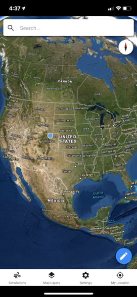
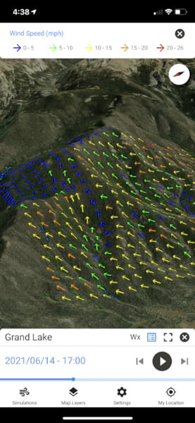
WindNinja is a high-resolution wind modeling app created for firefighters who need to quickly compute and visualize wind direction and speed simulations. The simulations provide them with situational awareness, help keep them safe, and help them conduct work such as burnout operations. The mobile app, developed using ArcGIS AppStudio from Esri, provides high-resolution, near-surface wind forecasts that include wind speeds and directions displayed on a map. The user selects an area of interest of 50 square kilometers or less, names the simulation, chooses a forecast duration of up to 15 hours, selects whether to receive an email or SMS notification when the simulation is ready to view, and then submits the request. The user also can select from a variety of basemaps and turn on data layers — vegetation, atmospheric, oceanic, land-surface imagery — collected by NOAA satellites.
Intelligent control system meets urban transport requirements
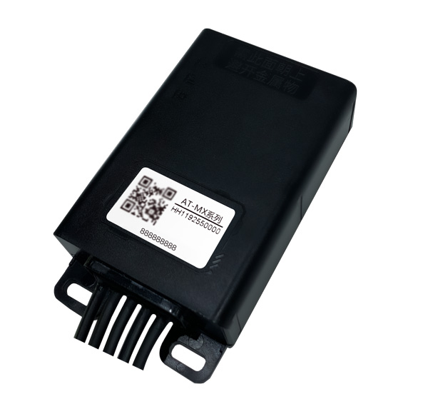
Photo: Xiaoan Technology
The AT-MX intelligent control system for shared electric bicycles uses the latest ultra-low-power u-blox M10 GNSS technology to enhance the positioning performance of their fleet for improved compliance with increasingly stringent Chinese policy requirements. The growing popularity of shared micromobility solutions for short-distance urban travel has led municipal authorities around the world to introduce new legislation to mitigate their perceived negative impacts, for instance, with restrictions on where users can drive and park their vehicles. Meanwhile, vehicle operators and maintenance personnel need to efficiently locate vehicles requiring maintenance and gather reliable vehicle usage data to balance bicycle placement and operational safety. Enforcing regulatory compliance and optimizing operations both require the safe, accurate and efficient bicycle positioning solutions.
Ensures safe operations through reliable, robust and continuous positioning
Image: Hexagon
SPAN technology delivers a deeply coupled GNSS and inertial navigation system (INS) that provides robust, reliable and continuous centimeter-level positioning for operators to maintain safety and maximize uptime. Now available for the dynamic positioning of vessels, the GNSS+INS solutions can bridge outages in GNSS tracking and through short periods of radio-frequency interference, jamming or spoofing. It provides vessels with an added layer of resiliency and achieve continuous centimeter-level accuracy across all conditions. SPAN GNSS+INS technology is compatible with commercial inertial measurement units (IMUs) and scalable with the LD900 GNSS receiver, Quantum visualization software and APEX correction services. Features include continuous centimeter-level positioning made more robust and reliable through enhanced GNSS tracking and deep coupling of inertial measurements; rapid reacquisition of GNSS signals after outages or interruptions through a deep coupling process; constant monitoring of GNSS absolute positioning combined with heading, velocity and attitude measurements; and added positioning redundancy with system robustness against potential signal outages, interference or disruptions.
Ibtechar, one of Qatar’s top providers of practical innovation and turnkey solutions, has developed a drone tracker and a GPS-based system that ensure the safety and security of critical infrastructure, VIP residents, national borders, and military facilities. The customized solution is made by a Qatar-based team of researchers and technologists with extensive knowledge and expertise in applied research and counter-drone systems. It aims to secure airports, power lines, and other vital assets that can be targets for drone attacks. Prototypes have gone through 487 flight tests in 19 locations, as well as 676 drive and walk tests. Features include compatibility with GPS, GLONASS and BDS; real-time tracking, popup notifications and SMS alerts; smart geo-fencing; drone whitelists/blacklists; base-station triangulation (cell ID); IMU, tilt, vibration sensor, and NFC; and offline mode. The new tracking system can identify the operating drones by displaying the drone itself, its serial number, the commercial frequency used, and motion details (speed, altitude, azimuth, path, etc.).
DroneDeploy lets users capture, process and analyze data in one platform. Users can create high-resolution 2D and 3D interior and exterior maps and models accurate to between 1 cm and 5 cm. It is designed for individuals, teams or enterprises and is suitable for all use cases and industries. However, primary markets include agriculture, construction, mining, energy, roofing and inspection. Features include Mobile Flight App to capture images directly from
an iOS or Android device; Live Map to create real-time, sharable
2D maps; Autonomous Flight to preprogram routes; as well as
360 Walkthrough for a 360-degree, virtual tour through a 3D model of a site. Industry-specific features are available, such as Plant Health to help farmers measure crop health and viability.


