In the current context of the Russian invasion of Ukraine, the issue of GNSS jamming and/or possible spoofing has intensified in geographical areas surrounding the conflict zone and other areas, according to the European Union Aviation Safety Agency (EASA). The agency issued a safety information bulletin on March 17 warning of a GNSS outage leading to navigation / surveillance degradation. According to the bulletin, which was directed at national aviation authorities and airlines, reports analyzed by EASA indicate that since February 24 GNSS spoofing and/or jamming has intensified in four key geographical areas:
the Kaliningrad region, surrounding Baltic Sea and neighboring states
Eastern Finland
the Black Sea and
the Eastern Mediterranean area near Cyprus, Turkey, Lebanon, Syria and Israel, as well as Northern Iraq.
“The effects of GNSS jamming and/or possible spoofing,” the bulletin stated, “were observed by aircraft in various phases of their flights, in certain cases leading to re-routing or even to change the destination due to the inability to perform a safe landing procedure.” It pointed out that in the present conditions it is not possible to predict these outages and their effects. Potential issues include:
loss of ability to use GNSS for waypoint navigation
loss of area navigation (RNAV) approach capability
inability to conduct or maintain various operations
triggering of terrain warnings, possibly with pull-up command and
inconsistent aircraft position on the navigation display
loss of automatic dependent surveillance-broadcast (ADS-B), wind shear, terrain and surface functionalities
failure or degradation of ATM/ANS/CNS and aircraft systems that use GNSS as a time reference and
airspace infringements and/or route deviations due to GNSS degradation.
The bulletin also offers several recommendations to airlines for mitigating these issues.
How inertial systems and GNSS availability will help
By Kana Nagai, Matthew Spenko, Ron Henderson and Boris Pervan
Self-driving cars in urban environments can be problematic. The required multi-sensor automated systems will include GNSS, but buildings block and reflect GNSS signals, reducing system availability and accuracy. Researchers from the Illinois Institute of Technology report on how inertial navigation systems coupled with wheel-speed sensors and vehicle dynamic constraints can help.
Innovation Insights with Richard Langley
ARE WE THERE YET? This was a familiar refrain from the backseats of parents’ cars when traveling to a holiday destination or to grandparents when I was growing up. We didn’t have videos on a display attached to the seats in front of us or (who could imagine?) our own personal communication device on which we could call up games, movies or social media channels.
But I’m not talking about that complaint from our childhoods. I’m asking if we have arrived at the era of the self-driving car. The answer is yes and no. It all depends on what you mean by “self-driving.” We reviewed some of the technologies needed for self-driving or autonomous vehicles in this column in June 2019. And we indicated in the introduction to that column that vehicle autonomy has several levels. SAE International, formerly known as the Society of Automotive Engineers, has defined six levels of autonomy that can be briefly described as Level 0 – no automation; Level 1 – hands on/shared control; Level 2 – hands off; Level 3 – eyes off; Level 4 – mind off; and Level 5 – steering wheel optional.
Already, Level 1 automation is widely available in modern cars with adaptive cruise control, parking assistance, lane-keeping assistance and automatic emergency braking among the features being offered.
Level 2 automation, where the automated system takes full control of the vehicle’s acceleration, braking and steering, is available in some production models, although the “hands-off” designation is not to be taken literally — most motor vehicle laws require drivers to keep their hands on the steering wheel.
Between Level 2 and Level 3, we have conditional automation — the car can drive itself, but the driver must stay alert and be prepared to take over immediately.
Level 3 is high automation, where a computer fully drives the car at certain times on certain routes such as a highway; while the driver can perform other tasks such as reading a book, they must be prepared to take over operation of the vehicle within a few seconds if alerted by the automated system. While test campaigns are still ongoing, some jurisdictions permit Level 3 operation by ordinary drivers on some roads, and customers will soon be able to buy vehicles with this level of automation. Widespread use of
Level 4 and Level 5 automation is further off (some would say quite a way off) and remains in development. But famously, last year, Toyota operated Level 4 self-driving shuttle vehicles around the Tokyo 2020 Olympic Village.
A lot more work needs to be done before we will have arrived at the era of the fully self-driving car that will be able to travel on any road, anywhere in the world, all year around, in all weather conditions. In particular, self-driving cars in urban environments (as opposed to highway driving) can be problematic.
The required multi-sensor automated systems will include GNSS, but buildings block and reflect GNSS signals, reducing system availability and accuracy. In “Innovation” this month, researchers from the Illinois Institute of Technology report on how inertial navigation systems coupled with wheel-speed sensors and vehicle dynamic constraints can help.
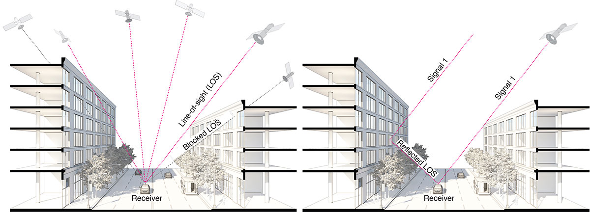
GNSS provides navigation services globally, but satellite visibility in urban areas is limited by high-rise buildings. This creates a mixture of GNSS available and denied environments (see FIGURE 1) — users do not generally know where the system can maintain sufficient levels of accuracy and integrity for a particular application. To begin to address the issue for self-driving cars, we evaluated GNSS-only availability in downtown Chicago.
FIGURE 1. The figure depicts three types of potential GNSS signal reception: direct LOS signals and blocked LOS signals (left) and reflected LOS signals (right). (Image: Authors)
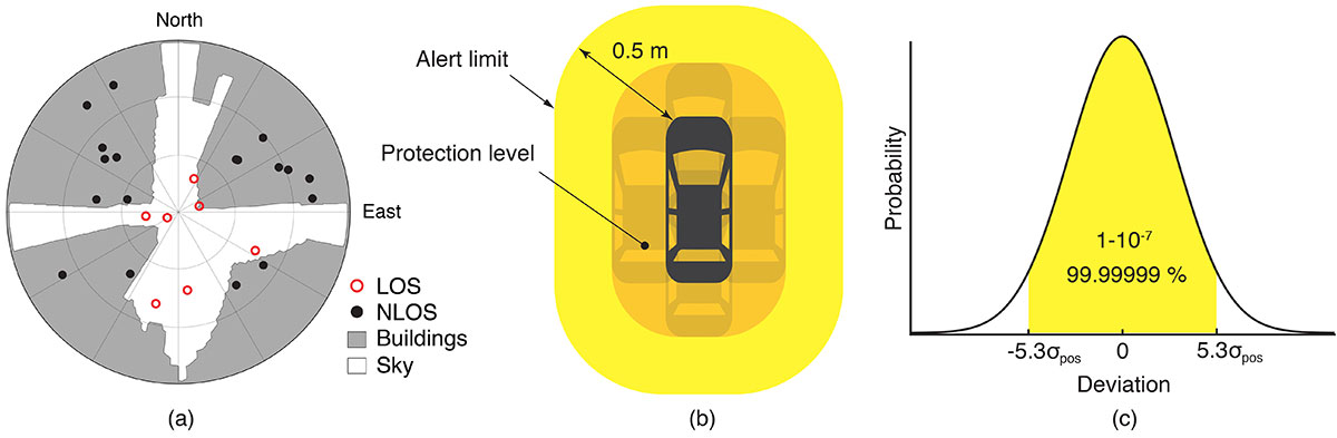
GNSS signal prediction in urban environments has been conducted in previous work. For example, the concept of “shadow matching” was developed to identify GNSS signal blockages in urban canyons. Overlaying sky plots on a hemispherical sky view can be used to distinguish between line-of-sight (LOS) and non-line-of-sight (NLOS) signals (see FIGURE 2a). Reflected rays can be predicted using Householder transformations to reveal potential multipath conditions. Satellites producing blocked or reflected (NLOS) signals should be excluded to maintain integrity.
FIGURE 2. (a) A hemispherical sky view in an urban environment. (b) Illustration of a protection level and an alert limit. To ensure integrity, the protection level must not exceed an alert limit. (c) The allowable probability of exceedance is assumed to be 10−7 in this work. (Image: Authors)
When the number of visible satellites is greater than three, GNSS can resolve vehicle position. However, even in cases where enough satellites are visible, the satellite geometries are generally weak because the dilution of precision (DOP) is adversely affected by the buildings partially blocking the sky. Horizontal positioning error must be bounded by a protection level computed by the vehicle. Then, for navigation to be deemed available, the protection level must not exceed a required alert limit (see FIGURE 2b). The maximum allowed probability of exceedance (see FIGURE 2c) and the alert limit can together be used to determine the maximum allowable position error standard deviation.
Even if the protection level is far below the alert limit in an open-sky environment, it will frequently exceed the alert limit once the vehicle enters a city. GNSS alone is generally not able to maintain availability, so integration with other sensors is needed. Tightly coupling inertial navigation systems (INS) with GNSS using the extended Kalman filter (EKF) provides better estimation in urban environments. The EKF algorithm also enables integration of wheel-speed sensors and vehicle dynamic constraints. These integrated navigation systems will improve availability, but it is still unclear how long such a system can be expected to maintain fault-free integrity in a congested city.
Focusing on the problem of self-driving cars in urban environments, we evaluate protection levels of navigation with practical integrated sensors: GNSS, INS, a wheel-speed sensor (WSS) and vehicle dynamic constraints (VDC). The goal is to develop the means by which we can determine locations where external ranging sources (such as lidar) are needed to maintain continuous navigation with fault-free integrity.
GNSS-ONLY AVAILABILITY
For GNSS availability evaluation, we assume an integrity requirement that the probability of exceeding a 0.5-meter alert limit must be lower than 10−7. The 0.5-meter alert limit therefore corresponds to approximately five times the position standard deviation, so the maximum allowable position error standard deviation is then approximately 0.1 meters. Accuracy at this level clearly requires differential GNSS carrier-phase measurements. We assume a nominal GNSS double difference (DD) carrier ranging error standard deviation of approximately 0.02 meters, and that carrier cycle ambiguities can be readily resolved in an open-sky environment prior to initiation of vehicle motion.
Given the assumptions made of the maximum allowable position error standard deviation and the GNSS ranging error standard deviation, the maximum allowable horizontal dilution of precision (HDOP) is about 5.
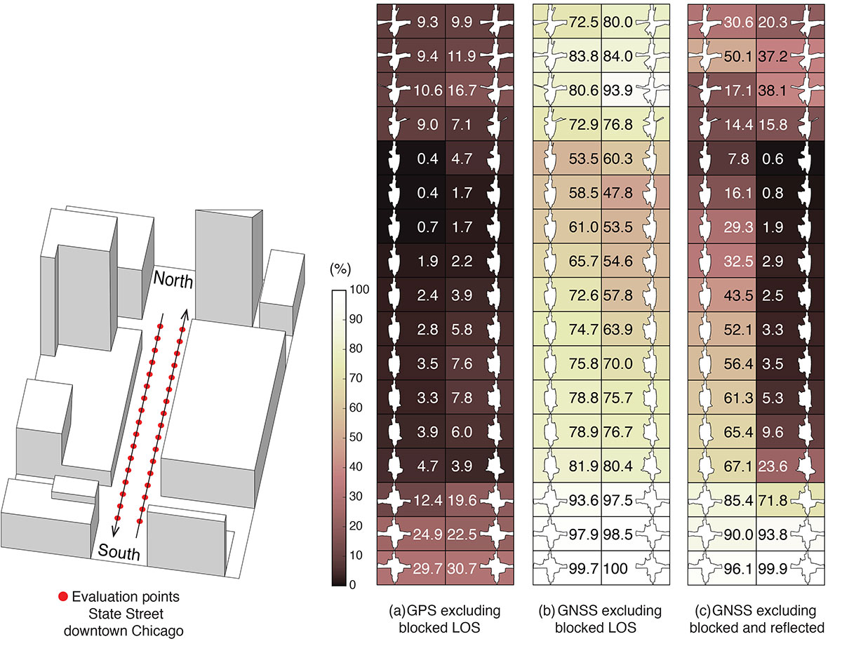
FIGURE 3 shows GPS and GNSS availability — the fraction of time the HDOP requirement is met over 24 hours — along a section of State Street in downtown Chicago. The availability results using GPS only and excluding only blocked LOS signals ranged from 0% to 9% along the block and 9% to 30% at the intersections (see FIGURE 3a). Using four full GNSS constellations (GPS, Galileo, GLONASS and BeiDou), availability ranged from 48% to 82% along the block and 72% to 100% at the intersections (see FIGURE 3b).
FIGURE 3. The percentage of GPS or GNSS availability in 3D-mapped downtown Chicago. We exclude satellites producing blocked LOS signals or both blocked and reflected LOS (NLOS) signals from the measurements. Each column expresses a lane of southbound or northbound travel. The availability is the percentage of total time when HDOP meets the self-driving car integrity requirements in 24 hours. (Image: Authors)
When we also excluded satellites producing reflected LOS signals that reach the vehicle, the availability dropped significantly at every point (see FIGURE 3c). We assert that FIGURE 3c expresses the reality of GNSS availability because building-reflected multipath signals degrade positioning accuracy and would affect integrity negatively. It’s obvious from these results that GNSS alone is insufficient to meet the autonomous driving requirements in an urban environment, and multi-sensor integrated navigation systems are needed to augment poor GNSS signal availability.
MULTI-SENSOR INTEGRATION
We begin by considering tightly coupled INS/GNSS integration using an EKF, and then integrate a realistic sensor suite including WSS and vehicle dynamic constraints that enforce resistance to lateral sliding and vertical movement. If it is known from another source that the vehicle is not moving (for example, it is in the parking gear), a static mode constraint (SMC) can also be applied.
INS/GNSS Integration. Tightly coupled INS/GNSS integration with an EKF uses the INS measurement to predict vehicle motion. The continuous process model uses a state vector having the position in the navigation frame, the velocity, the attitude, bias errors and cycle ambiguities, with the input vector having accelerometer-specific force measurement in the body frame and gyro-rotation-rate measurements. A white-noise vector drives the inertial measurement unit (IMU) states.
The GPS/GNSS measurement model includes the measurement vector having carrier and code phases, and the observation matrix containing LOS vectors and the vector of white receiver thermal noise.
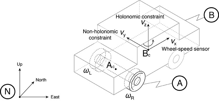
INS/GNSS/WSS/VDC Integration. For the vehicle in motion, we developed a model consisting of a WSS measurement in the along-track direction, a non-holonomic constraint resisting lateral sliding, and a holonomic constraint on vertical movement (see FIGURE 4).
The INS/GNSS/WSS/VDC integration using the EKF consists of the process model and the measurement models.
FIGURE 4. The measurement model consisting of the WSS measurement in the along-track direction (vx), non-holonomic constraint resisting lateral sliding (vy), and holonomic constraint on vertical movement (vz). N is the navigation frame, Ac is the rear-axle center point and Bc is the center point of the body-fixed frame. (Image: Authors)
INS/GNSS/SMC Integration. The static mode constraint provides zero-velocity measurements to the EKF measurement update to mitigate position error propagation. We use SMC only when it is known that the vehicle is not moving; for example, when the vehicle is in the parking gear.
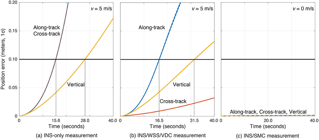
Error Propagation Analysis. We tested the time from perfect initialization to when position error exceeds 0.1 meters in GNSS-denied environments. FIGURE 5 shows the error growth in the along-track (x), the cross-track (y) and the vertical (z). The error specifications for a STIM300 tactical-grade IMU are used in this analysis. The standard deviation of the WSS measurement noise is assumed to be 0.05 meters per second, and the standard deviation of the movement constraint violations is 0.001 meters per second. The vehicle is moving at 5 meters per second except when we test the SMC.
The INS can coast 15.6 seconds before the position error standard deviation exceeds 0.1 meters in both the along-track and the cross-track directions (see FIGURE 5a). The INS/WSS/VDC can coast 16.5 seconds in the along-track direction, and significantly more than 40 seconds (the simulation duration) in the cross-track direction (see FIGURE 5b). In static mode, INS/SMC estimate errors do not grow with time in any direction, as expected (see FIGURE 5c). In GNSS-denied environments, the non-holonomic constraint suppresses the cross-track position error, but the WSS measurement hardly affects the along-track position error. The SMC works perfectly, but the usage is limited to when the vehicle is known to be stationary.
FIGURE 5. The vehicle position error growth vs. time in the along-track (x), cross-track (y) and vertical (z) directions. Each graph represents the navigation system introduced in the multi-sensor integration section. The vehicle is moving at 5 meters per second (a and b) or 0 meters per second (c). (Image: Authors)
SIMULATION SCENARIO
We imagine a future driverless-car mission scenario in which multi-sensor navigation systems are practicable. To minimize congestion in a city, autonomous vehicles will be held outside the urban core when not in use. In the clear open-sky environment, a vehicle in a parking lot completes GNSS initialization using the INS/GNSS/SMC system. Once requested for action, the vehicle departs for the city from the parking lot, and the motion of the vehicle improves alignment by the INS/GNSS system. Safe navigation can be ensured using the system to provide continuity under overpasses and bridges in the open-sky environment. Upon entering the urban core, navigation becomes more dependent on the INS/WSS/VDC system.
A reasonable numerical target for differential GNSS initialized position error is 0.02 meters, and for the INS alignment yaw angle error 0.1 degrees.
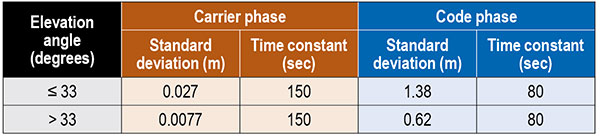
Local GNSS multipath errors from nearby vehicles will vary with the satellite elevation angle. Prior experimental results show that lower elevation-angle satellite signals (below 33 degrees) are much more likely to be impacted by multipath than higher ones (see TABLE 1).
Table 1. The nominal GNSS multipath error values in the simulation.
INITIALIZATION AND ALIGNMENT
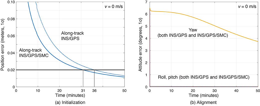
Initialization takes place in a parking lot with a clear sky view. A vehicle is in the parking gear, enabling SMC to be applied. FIGURE 6a shows a typical example: with INS/GPS/SMC, system initialization takes about 31 minutes, and with INS/GPS, about 36 minutes. Therefore, SMC does speed up GPS initialization, although the improvement is modest.
The yaw angle is not aligned during the initialization, but roll and pitch are immediately aligned (see FIGURE 6b). Earth’s gravity affects roll and pitch angle alignment but not yaw angle.
Yaw angle alignment cannot be performed when the vehicle is stationary or moving with constant velocity. Accelerated motion, either straight or turning, is required.
FIGURE 6. (a) Comparisons of initialization time between INS/GPS and INS/GPS/SMC in an open-sky environment. The INS/GPS/SMC system initializes rapidly. (b) Transitions of roll, pitch, yaw alignment during the initialization. Yaw angle alignment cannot be performed when the vehicle is stationary. (Image: Authors)
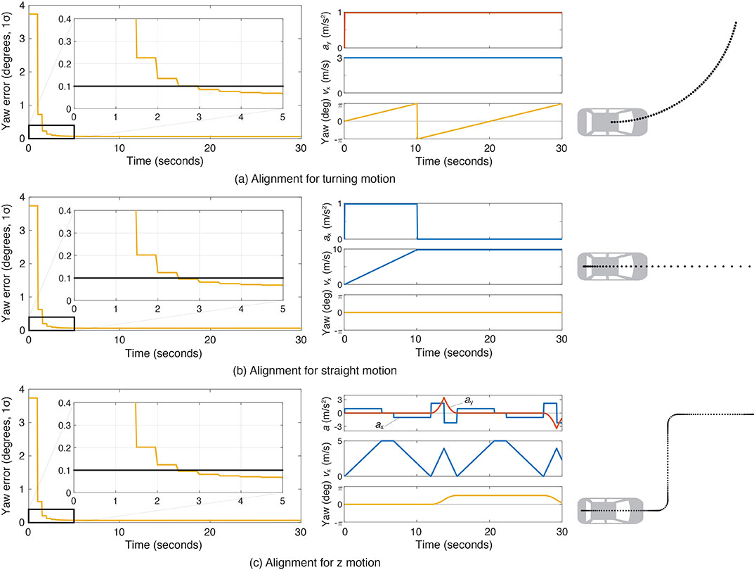
FIGURE 7 shows the behavior of the yaw angle error standard deviation using the INS/GPS system when centripetal (see FIGURE 7a) or tangential (see FIGURE 7b) acceleration is applied. The yaw angle can be aligned in a couple of seconds for either type of acceleration. To represent typical initial motions of self-driving cars, we model a parking-lot departure via a “Z”-shaped path. In this scenario, the yaw alignment error reaches 0.1 degrees within a couple of seconds (see FIGURE 7c).
FIGURE 7. The behavior of yaw angle error when centripetal (a) or tangential (b) acceleration is applied; (c) shows the behavior while following a z-shaped path. The yaw angle can be aligned in a couple of seconds in each case. (Image: Authors)
EVALUATION IN URBAN ENVIRONMENTS
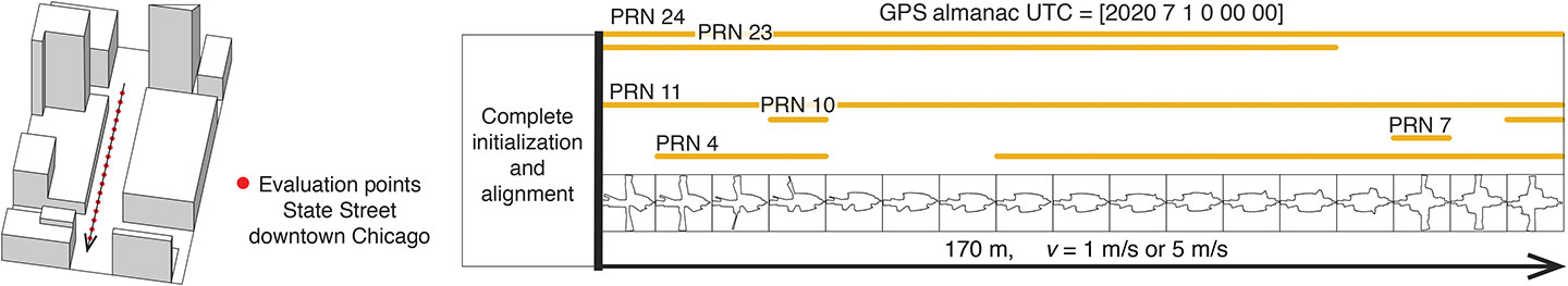
After initialization and alignment in the open-sky environment, we simulated the vehicle traveling into the urban core. The urban environment in our study is 3D-mapped State Street in Chicago, which runs north-south and transits from low-rise neighborhoods to central downtown. We selected one congested section surrounded by tall buildings and computed the position error standard deviation along the path. The evaluation points are at 10-meter intervals over a total distance of 170 meters. The yellow lines in FIGURE 8 denote the visible satellites, identified by their pseudorandom noise (PRN) code numbers, at each point. We assume for convenience that the INS/GPS system is initialized and aligned at the first evaluation point. In reality, we would expect a degraded initial condition because we are starting the simulation in an urban canyon.
FIGURE 8. Evaluation points and PRN numbers of visible satellites at each point. (Image: Authors)
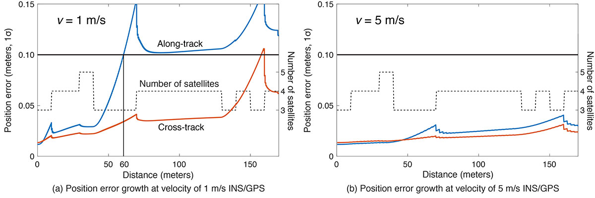
In the first simulation, the car equipped with the INS/GPS system moved either 1 or 5 meters per second. The y-axis in FIGURE 9 represents the position error standard deviation, and the x-axis represents the distance in meters. The dotted line expresses the number of visible satellites. The error when the vehicle velocity is 1 meter per second exceeded the maximum allowable position error standard deviation of 0.1 meter, at the distance of 60 meters. However, when the velocity was 5 meters per second, the maximum allowable position error standard deviation was never reached. It is also clear from the figures that error propagation is significantly affected by the number of visible satellites.
FIGURE 9. A comparison of position error growth between velocities of 1 meter per second and 5 meters per second. (Image: Authors)
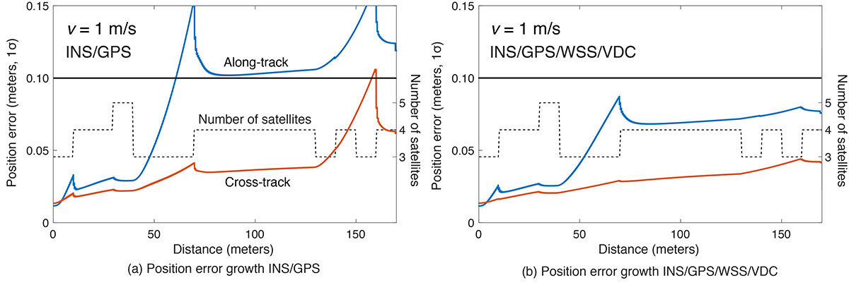
In the second simulation, we compared two different navigation systems, INS/GPS and INS/GPS/WSS/VDC. The vehicle moved at 1 meter per second in the same urban environment. The INS/GPS/WSS/VDC system does provide relief, but the error propagation is still clearly affected by the number of visible satellites (see FIGURE 10).
FIGURE 10. A comparison of position error growth between the INS/GPS and INS/GPS/WSS/VDC systems for a velocity of 1 meter per second. (Image: Authors)
In GNSS-challenged environments, INS error propagation is a function of time. When a vehicle moves faster, it clears the blockage area more quickly, reducing the impact of INS drift — a function of time, not distance. In contrast, GNSS error is completely determined by location. Because INS error propagation depends on how long the vehicle stays in an area of GNSS outage, protection levels for trips through the same area will be different if the vehicle is smoothly cruising or gets stuck in a traffic jam.
CONCLUSION
To gain a better understanding of how long and under what local conditions multi-sensor integrated navigation systems can maintain fault-free integrity, we evaluated navigation positioning errors in 3D-mapped downtown Chicago. The system we developed consists of sensors with which self-driving cars would reasonably be equipped: GNSS, INS, WSS and dynamic constraints. We showed that INS/GPS position errors along the path depend very strongly on the vehicle’s speed. When the system is augmented with WSS/VDC, position errors are suppressed, but the error propagation is still strongly influenced by the number of visible satellites.
ACKNOWLEDGMENTS
The research described in this article is supported by the National Science Foundation. Figure 1 was created by Alexis Arias of the Landscape Architecture + Urbanism Program at the Illinois Institute of Technology (IIT). The authors greatly appreciate the advice and help of Nilay Mistry from that program.
This article is based on the paper “Evaluating INS/GNSS Availability for Self-Driving Cars in Urban Environments” presented at ION ITM 2021, the virtual 2021 International Technical Meeting of The Institute of Navigation, Jan. 25–28, 2021.
KANA NAGAI is a Ph.D. candidate and research assistant in mechanical and aerospace engineering at IIT.
MATTHEW SPENKO is a professor of mechanical and aerospace engineering at IIT. He earned his M.S. and Ph.D. degrees in mechanical engineering from the Massachusetts Institute of Technology.
RON HENDERSON is a professor and director of the Landscape Architecture + Urbanism Program at IIT. He earned his Master of Landscape Architecture and Master of Architecture from the University of Pennsylvania.
BORIS PERVAN is a professor of mechanical and aerospace engineering at IIT. He earned his M.S. from the California Institute of Technology and Ph.D. from Stanford University.
Although GNSS has been applied in agriculture for many years, farmers still encounter challenges caused by GNSS. No matter the farm task — planting, spraying, harvesting or specialized applications such as robotic grass mowing — position accuracy matters.
Here are the most common issues farmers have and how Unicore’s products help.
Under canopy. They are unable to get a fix under heavy foliage canopy because the real-time correction signal is interrupted or “shaded out” by the canopy. Unicore is launching two new modules that will help mitigate this problem.
Loss of lock. At times, the receivers lose lock or get large position errors when the ionosphere’s effects are severe. Driven by a full-constellation and full-frequency RTK engine, Unicore’s RTK algorithm takes advantage of triple and quad frequency observables, effectively mitigating ionospheric residuals.
Loss of 4G signals. RTK can provide real-time centimeter-level high-precision positioning, which requires real-time base station data. In practical applications, radio or wireless network communication is often interrupted. During the interruption of the base station data, RTK’s positioning accuracy decreases quickly. Unicore’s RTK KEEP technology can maintain the centimeter-level positioning accuracy for more than 10 minutes after the interruption.
Lack of CORS stations. It is challenging to provide a stable high accuracy position for an ultra-long baseline. With the mitigation of ionospheric and tropospheric delays, Unicore products’ RTK baseline can be extended to up to 50 kilometers.
The UM980 is Unicore’s new-generation high-precision RTK positioning module, supporting full constellation and full-frequency. Relying on the strengths of high reliability, precise positioning accuracy and low latency, UM980 is not only well suited for high-precision surveying and mapping, but also a good choice for rover or base station receivers in agriculture.
The UM982 is a dual-antenna high-precision positioning and heading module. Since its master and slave antennas can simultaneously track all the frequencies of all the GNSS systems, the UM982 performs fast on-chip RTK positioning and dual-antenna heading solutions without the need to initialize the IMU. Featuring great positioning performance and stability, the UM982 is a perfect choice for high-precision agriculture applications, such as drones, autonomous tractors and autonomous lawnmowers.
ION’s winter meeting, the International Technical Meeting (ITM), is a more intimate conference with a technical program related to positioning, navigation and timing and includes the ION Fellows and Annual Awards presentations.
In 2022, ITM will take place in Long Beach, California, Jan. 25-27, and will be co-located with the Precise Time and Time Interval Systems and Applications Meeting. ITM will house more than 150 in-person and virtual technical presentations, two keynote addresses, six tutorials, and an exhibit hall filled with the latest PNT solutions.
A commercial exhibit and pre-conference tutorials are held in conjunction with the conference.
Tutorials will be offered as part of this year’s in-person technical program on January 26 and will be open to all in-person PTTI and ITM attendees. Tutorials cover novel systems for time distribution from space, atomic clocks, Kalman filtering for clock estimation, and specific implementations for time distribution from space.
The ITM/PTTI plenary session will be recorded and uploaded to the website for on-demand viewing. No other ITM/PTTI sessions (including tutorials) will be recorded for on-demand viewing. All presenters are required to provide a video presentation for on-demand viewing. On-demand presentations will be available through the ITM/PTTI meeting portal for 30 days.
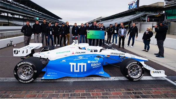
Flipping the traditional scenario, in which car racers risk their lives on a racetrack, the Indy Autonomous Challenge (IAC) aimed to help save lives by improving collision avoidance systems, train future automotive engineers, and make the public more comfortable with autonomous cars. Held Oct. 23 at the Indianapolis Motor Speedway and organized by Energy Systems Network, the race saw 21 universities from nine countries forming nine teams to compete for a $1 million grand prize. Following in the footsteps of the DARPA Grand Challenge, first held in 2004 and later renamed the DARPA Urban Challenge, the IAC was the world’s first high-speed autonomous race. The winning team was TUM Autonomous Motorsport from the Technical University of Munich, Germany.
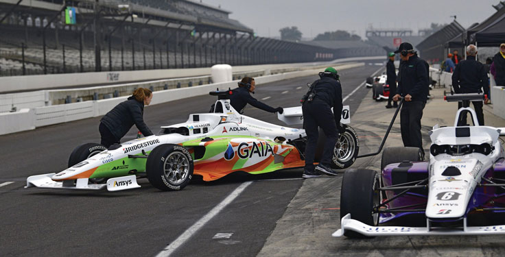
All competing teams were given the same identical vehicle to work with, a Dallara AV-21, modified to carry no one in the cockpit and equipped with two Hexagon | NovAtel PwrPak7-Ds multi-frequency, multi-constellation GNSS receivers, six cameras (two of which faced backward), three lidar scanners and four radars. Each team had to develop its own autonomy-enabling software stack, including the algorithms and neural networks. All the components, except the computer, had to be commercial-off-the-shelf, available on the market. No sensors could be custom-made.
Since 2001, Dallara has been the sole supplier of the Indy Lights series, a championship to prepare drivers for the NTT IndyCar Series. The Dallara AV-21 is a collaboration between Dallara’s Italian headquarters in Varano Melegari (Parma) and Dallara IndyCar Factory in Speedway, Indiana. The new car offers a modern, stylish appearance and provides the proper training required for drivers as the final step on the ladder to the NTT IndyCar Series.
The process by which the automated vehicle sensors and computers were fused into a singular package and integrated into the AV-21 was led by Clemson University’s International Center for Automotive Research’s Deep Orange 12 (DO12) project. The Deep Orange process mirrors that of automotive original equipment manufacturers (OEMs), and the DO12 project scope allowed for engineering and innovation across multiple subsystems. Student groups within the DO12 team explored solutions within and across multiple subsystems, including:
vehicle-to-vehicle communications
perception systems
onboard computing
drive-by-wire chassis control systems
vehicle dynamics
vehicle-to-infrastructure communications
powertrain design and integration
vehicle demonstration based on high precision GPS.
Hexagon’s Autonomy & Positioning division provided GNSS receivers and subject-matter experts to the Deep Orange 12 team. The team architected the sensor kit for the Dallara reference vehicle, which AutonomousStuff then replicated 10 times. The team did not compete in the IAC to avoid a conflict of interest and allow students to work closely with competitor teams from universities around the world. The PwrPak7-E1 contains a MEMS IMU to deliver Hexagon | NovAtel’s SPAN technology, a deeply coupled GNSS + inertial engine in a single-box solution. Each GNSS receiver has two antennas to provide heading. The Deep Orange 12 team used HxGN SmartNet RTK corrections, which brought the accuracy down to a few centimeters.
Without developing a driverless decision-making algorithm, Clemson students tested the vehicle with the help of a high-precision positioning system. They developed a control algorithm that can track the optimal line around the Indianapolis Motor Speedway such that all vehicle systems could be validated in a simulated racing environment. Data from these tests were shared with the competition teams to aid in their development of driverless algorithms.
Energy Systems Network will host a head-to-head, high-speed autonomous racecar passing competition at the Las Vegas Motor Speedway on Jan. 7, 2022, during the Consumer Electronics Show. Several of the teams that competed in the IAC, including the winner and finalists, will participate. The primary goal is to advance technology to speed commercialization of fully autonomous vehicles and deployments of advanced driver-assistance systems.
Swiss company u-blox designs and manufactures GNSS receivers used in the automotive market, including driverless cars, and for micro-mobility devices, such as the Bird scooter.
In deep urban canyons, the biggest challenge for positioning cars is achieving sufficient accuracy despite multipath, said Aravinthan Athmanathan, product manager for the company’s Automotive GNSS line of receivers. “The challenge for autonomous driving is reliable lane-accurate positioning and integrity.”
The company develops its own dead-reckoning algorithms, which use data from an inertial measurement unit (IMU) and wheel speed sensors. “We also provide dual output, so the end customer can choose whether to use GNSS only or a sensor-fused solution,” said Athmanathan. This is especially challenging at the sub-meter accuracy level.
Different Uses, Different Sensors
Different automotive use cases require different GNSS receivers. To meet this challenge, u-blox offers the NEO-M9L for standard precision and the ZED-F9K for high precision, depending on the customer’s needs. Additionally, it is investing a lot “in functionally safe GNSS and in being the GNSS enabler for car manufacturers,” said Karin Steinhauser, the company’s senior marketing communications manager.
For navigation with meter-level accuracy, the NEO-M9L is integrated with dead-reckoning technology and sensor fusion, using algorithms that process sensor data from the IMU and from wheel-speed sensors. It can provide reliable location data in challenging environments, such as urban canyons, where multipath becomes an issue, or tunnels, where GNSS signals are partially or totally denied, Steinhauser said. Additionally, the NEO-M9L can operate in temperatures of up to 105° C, making it suitable for integration on the roof, behind the windscreen, or inside hot electronic control units. The NEO-M9L addresses the use cases in urban environments for both navigation and systems, such as Europe’s eCall, that provide an automated message to emergency services following a road crash, including the precise location of the accident.
The ZED-F9K, on the other hand, is well suited for use cases at the higher levels of advanced driver assist systems (ADAS) defined by the Society of Automotive Engineers (SAE), which require decimeter-level accuracy. “At L3 and above, you need correction services with integrity to allow for trustworthy and reliable GNSS positioning,” Steinhauser said. “We have partnerships with Bosch on projects to develop functionally safe GNSS solutions based on a ISO26262-certified version of u-blox generation 9 GNSS technology.” The ZED-F9K is a multi-band receiver that uses GPS signals on L1-L2 and Galileo signals on E5b. “We also have a special set of features adequate for the ADAS and the autonomous driving features,” Athmanathan said.
Image: 3alexd/E+/Getty Images
Bottlenecks
One of the factors limiting how quickly u-blox can roll out solutions based on the ISO 26262 standard (titled “Road vehicles – Functional safety”) is that highly autonomous systems require more integration work by the customers, said Alex Ngi, the company’s product manager for High Precision GNSS. “The first systems are now available.” Another hurdle, he pointed out, is the legal framework for deploying autonomous driving systems. “The regulations about how things need to be tested, and the liabilities for when systems fail, affect how quickly these systems can get adopted.”
GNSS can be used as a complementary technology to enable absolute positioning for systems that fuse data streams from cameras and lidars, such as those used for ADAS level 2 applications. “Fusing all this is computationally intensive and requires high processing power, such as NVIDIA GPUs, which tend to be very hot systems. We see a lot of requirements for very high-temperature GNSS receivers, because our receivers are often co-located with these hot systems.”
Of course, u-blox does not simply hand its modules to Bosch and car manufacturers and say, “You take it from here.” Design and integration is an iterative process. “We bring in the GNSS know-how and integration support and Bosch brings in the functional safe automotive development know-how,” Ngi said.
Dead Reckoning and Map Matching
For the automotive market, u-blox has more than 20 years of experience with dead reckoning. “The sensor-fusion solution receives data from both the GNSS and the IMU, and we provide the complete final solution,” Athmanathan explained.
The system also aids the receiver by providing it external map data. “If you’re driving your car northbound and the GNSS receiver tells you that it’s headed in the opposite direction, or that you’ve jumped over to the lane to the other side of the highway, clearly that cannot be right,” Ngi said. “Map matching relies on simple messages that come into our receivers to give us positive feedback on our measurements.”
For non-automotive applications, u-blox makes the ZED-F9R. It is used, for example, in robotic lawnmowers, very common in Asia and Europe, which require centimeter-level accuracies. “That’s why it focuses on delivering corrections using SPARTN, which can be a continent-wide data stream,” Ngi said. “We also make the design so that it’s very easy to integrate and enables the designers to easily pass the corrections to their receivers fully encrypted. This way, the value of the data is delivered to the lawnmower without exposing it to the system designer, so that we don’t need to go check every design to see whether somebody is leaking secured correction services.”
By the end of November, according to u-blox, updates of the ZED-F9P multi-band GNSS receiver will include decryption of the SPARTN correction data and a 95-percentile protection level. The protection level increases the trust non-safety-critical applications can place in its position output. By continuously outputting the upper bound of the maximum likely positioning error, referred to as the protection level, the receiver lets autonomous applications, such as UAVs or robotic lawnmowers, make efficient real time path planning, increasing the quality of their operations.
Guiding eScooters and EVs
In some places, Ngi pointed out, e-scooters are required to use a bike lane, which might be only two or three feet wide and may not be along the side of a building as it would be on a sidewalk. “The ZED-F9R is a much more flexible solution than camera systems that only know sidewalks or bike lanes.” Bird uses it to throttle driving speeds to match speed limits, which change from one location to another. “It is also much more scalable for them as opposed to such solutions as using UWB [ultra-wideband] beacons to fence off different areas, which are not really scalable for a company that wants to deploy solutions to hundreds of cities.”
Xpeng Motors, a manufacturer of smart electric vehicles, uses u-blox F9 GNSS receivers, which use signals from all four GNSS constellations, in its P7 super-long-range sports electric vehicle sedan. The vehicle uses ADAS for navigation-guided driving, automated parking and autonomous driving. For instance, once a navigation destination is set on a specific highway, the P7 will follow the route guidance to execute autonomous lane changing, switch to high-speed routes, and select the optimal route in real-time.
A roundup of recent products in the GNSS and inertial positioning industry from the December 2021 issue of GPS World magazine.
OEM
Satellite-cell terminal
With built-in GPS receiver
Photo: OQ
OQ Technology’s dual-mode satellite-cellular IoT modem and tracker is a plug-and-play, small, low-cost and low-power solution that can collect data from more than 1,000 sensors. It has a built-in GPS receiver and supports 5G NB-IoT, GSM, LTE-M and bi-directional satellite links. The flexible, robust and programmable dual-mode terminal has pre-paid data packages suitable for remotely monitoring and controlling fixed and mobile assets in industries such as transportation, oil and gas, utilities, and maritime.
Provides mission-critical, extended length GPS over fiber
Photo: ViaLite
ViaLite’s GPS over Fiber Extension Kit for Microchip/Microsemi GPS timing servers provides mission-critical GPS timing and synchronization for systems requiring extremely accurate clock signals. Standard transmission distances for the extension kit can be up to 10 km, while solutions are available for distances as long as 50 km. The ViaLite kit was chosen for its unique performance with Microsemi’s S650 timing server. The ViaLite GPS link is designed to provide a remote GPS/GNSS signal or derived timing reference to equipment located where no signal is available, such as inside buildings or tunnels. By using optical fiber instead of traditional coaxial cable, extreme distances are possible with no radio frequency loss and zero introduction of noise.
The RELY-MIL-TIME-SERVER, which complies with MIL-STD-810G and MIL-STD-461G, embeds the latest timing, networking and security technology in a single SWaP platform. The all-in-one rugged edge computing device acts as a high-performance master clock and serves secure accurate timing distribution (PTP, NTP, GNSS). The timing feature is combined with high-bandwidth and high-availability Ethernet switching and L2/L3 cybersecurity services in a unique commercial-off-the-shelf device. At its heart is a Xilinx Ultrascale+ MPSoC device powered by SoC-e hardware IP cores for PTP and high-availability low-latency Ethernet networking.
The M-G370PDS0 inertial measurement unit (IMU) is equipped with a high-performance six-axis sensor. It has an angle random walk (short-term variation in output) of 0.03°/√h, which is half that of its predecessor, and can more accurately detect very slight changes in the attitude of equipment and systems, since they do not get lost in sensor noise. The small size, light weight and low power consumption will help customers make their own products smaller and lighter. It also maintains compatibility with earlier products (the M-G370/365/364/354), making performance upgrades easy.
The OSA 5400 SyncModule enables technology suppliers to integrate precise synchronization into their hardware. Its M.2 form factor can add timing capabilities to switches, routers, open compute servers and other IT devices. The SyncModule provides GNSS, precision time protocol (PTP) and network time protocol (NTP) engines as well as comprehensive PTP and GNSS monitoring and assurance functionality. It can enable assured sub-microsecond timing in public and private networks as well as critical infrastructure. Featuring multiple interface options for easy integration, the OSA 5400 SyncModule comes with an open API. It also can be managed by ADVA’s proven Ensemble Sync Director management system.
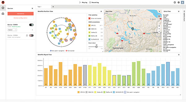
Running on Microsoft Windows, u-center 2 offers anyone working with 10th-generation (M10) u-blox GNSS technology a highly intuitive interface to configure GNSS products, evaluate their performance, improve the quality of their software, and experience the performance boost achieved using GNSS-related services. The software is the successor to the u-center GNSS evaluation software, which has been used by design engineers for almost two decades to develop GNSS receiver applications. Compatible with u-blox M10 GNSS technology, u-center 2 is designed to offer improved performance over its predecessor. New features in u-center 2 simplify configuration, evaluation and software development of GNSS-based solutions. It is free for download.
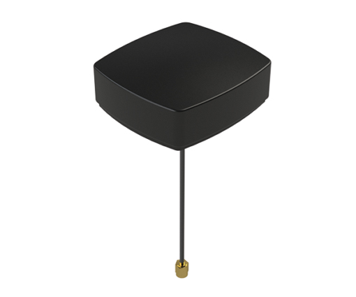
The MEA-1227-SM is a GNSS/L1 and L2 low-profile screw-mount antenna. It has high performance suitable for maintaining constant network connectivity. The MEA-1227-SM covers all GPS/GLO/BEI/ QZSS/Galileo/SBAS/L1L2 standard frequencies. It is designed for telematics systems, remote surveillance, asset tracking and any internet of things (IoT) system applications. This screw mount antenna is easy to install, with a low profile suitable for challenging installations. It has a IP67-rated housing and anti-rotation mounting.
The Cowboy e-bike solution provides riders with high-performance, real-time GNSS accuracy, enabling them to map their own paths and those of the cities in which they live. It uses smart road-companion applications to ensure riders get precise information, regardless of the route they travel. The positioning component uses Taoglas’ Accura GVLB258.A, a multi-band GNSS L1/L5, high-performance stacked patch antenna, in conjunction with u-blox’s SAM-M8Q GNSS positioning module. The combination allows for extremely low power and high accuracy. The solutions works with “micromobility” services offered by Cowboy, such as Easy Rider for theft detection, bike insurance and crash detection notifications.
Instant decimeter-level accuracy with automotive sensors
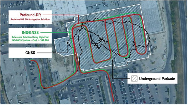
Photo: Profound Positioning
The Profound-IVT (instant vehicle tracking) provides cost-effective vehicle navigation. Based on a firmware library, and rapidly adaptable to any navigation platform, IVT combines precise point GNSS positioning (PPP), dead reckoning and radar technologies in an integrated solution to provide decimeter-level positioning accuracy plus orientation and velocity. IVT performs in tunnels, dense urban environments, multi-level highway junctions and parking garages. With errors <1% of distance travelled, resolution is extremely rapid. Base stations are not required and there are no operating range limitations. Applications include driver assistance, mobility and taxi, autonomous vehicles, geofencing, fleet tracking, insurance, driving and safety management, and connected driving.
Off-the-shelf map data through the HxGN Content Program
Photo: Hexagon
Metro HD city data is a new offering of ultra-high-resolution 2D and 3D digital twins of major cities. Metro HD expands the data stack to include high-definition true orthophotos, obliques, digital terrain models, lidar point clouds, 3D building models (LOD2), 3D meshes and land-use maps. Cities captured in 2021 include Munich, Cologne, Vienna, Milan, Amsterdam, Stockholm, Tokyo, Dallas, New York, Stuttgart and Frankfurt. More cities will be added in early 2022. The program uses a hybrid urban mapping sensor, the Leica CityMapper-2, that concurrently collects lidar and aerial imagery. The derived products, based on the strength of each subsystem, result in superior accuracy and temporal consistency across all three data dimensions.
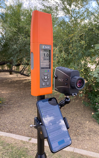
Bad Elf LLC and Laser Tech are providing an integrated laser offset workflow for acquiring high-accuracy field data in GNSS-challenged environments. The new workflow integrates Bad Elf and LTI hardware in collaboration with ArcGIS technology from Esri. The Bad Elf Flex GNSS receiver connects to any LTI TruPulse rangefinder over a wired or Bluetooth connection to deliver high-accuracy location data to Esri ArcGIS Field Maps. Field workers can now efficiently complete position and height data collection in access-limited situations, saving time, money and effort. The Bad Elf app workflow runs on Android and iOS.
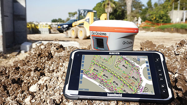
Geo-genie is a cloud-based collaborative and professional mapping and surveying platform enabling customization and creation of geocentric information systems. Teamed with Handheld’s Algiz RT8 rugged field tablet, it streamlines work and allows non-professionals to perform accurate geodetic mapping, guiding and monitoring of their data collection. The platform enables organizations to have an advanced, professional surveying and GIS platform with customized procedural workflows, management of user hierarchies, and integration with other organizational information systems. Geo-genie can connect with professional surveying equipment, such as GPS and total stations, and integrates data into a cloud-based central database with no restriction for specific data-collection hardware.
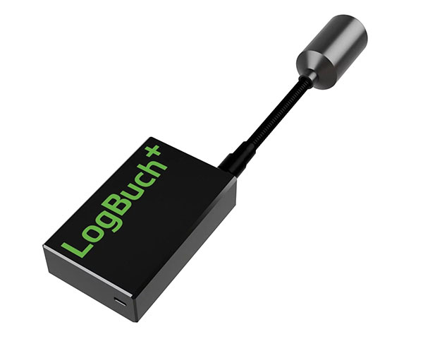
The wireless GNSS amplifier LogBuch+ increases the accuracy of location data with the cloud-based LogBuch application. The app enables voice-based digital mapping via a smartphone app, such as for the maintenance of trees. The compact device receives satellite signals on several radio frequencies, delivering significantly more precise data than a smartphone alone. Foresters can carry the GNSS amplifier in a pocket and digitally mark trees for felling using the LogBuch app.
The YellowScan Explorer lidar can be mounted on a light manned aircraft or helicopter, as well as a UAV platform such as the DJI M300. This versatility allows the end user to tackle a wide range of projects with the same unit. It uses an Applanix APX-20UAV GNSS/inertial solution and has a precision of 2.6 cm and an accuracy of 2.2 cm. Its high-power laser scanner can catch points up to 600 meters away. Flight operation speed is 5–35 m/s; it is capable of above-ground-level altitude up to 300 m. The low-weight unit (2.3 kg without battery) can be combined with YellowScan’s suite of software to extract and process point cloud data for surveying, forestry, environmental research, archaeology, industrial inspection, civil engineering and mining sectors.
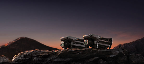
The DJI Mavic 3 improves on its predecessor with better sensors, a dual-camera system, omnidirectional obstacle sensing, smarter flight modes and longer flight times. A powerful positioning algorithm improves hovering precision with signals from GPS, GLONASS and BeiDou satellites, enabling the drone to lock onto multiple satellite signals faster. The increased positioning precision also makes the drone less likely to drift in the air and more stable when shooting long exposures and time lapses. The Advanced Pilot Assistance System (APAS) 5.0 combines inputs from six fish-eye vision sensors and two wide-angle sensors to sense obstacles in all directions and plan safe flight routes.
Conduct missions, manage fleets and view video feeds
Photo: SkyGrid
SkyGrid’s autonomous remote UAV operations solution enables drone operators to remotely conduct missions, control flights, manage fleets and view live video feeds. Using artificial intelligence and airspace-related data feeds, SkyGrid enables safe remote operations, whether conducting routine inspections or generating optimal flight paths. Advanced route generation capabilities create the safest route for each drone based on the flight plan, environmental conditions, the vehicle’s performance, and the mission criteria with minimum on-site support required. SkyGrid Launch allows video feeds from drones to be consolidated to a remote central location, such as a ground station.
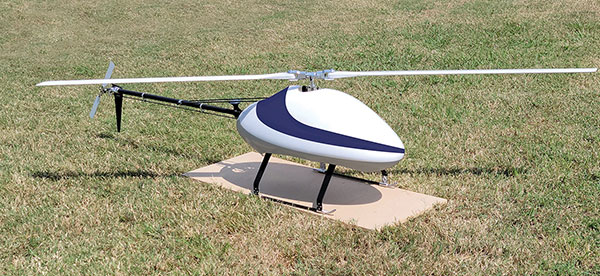
The Sicura EG-1100 is a heavy-lift, long endurance, single-rotor helicopter. Now in its third generation, the helicopter can haul 15 pounds. It cruises at 55 knots. The EG-1100 is available in both electric and gas engine configurations, with an endurance at 3.5 hours on gasoline and 1 hour on electric power. The new gas engine is the high-performing and efficient Skypower 110, tuned to the craft’s internally developed chassis and rotor blades. It offers stable performance in challenging environmental conditions, exceptionally stable flight and immediate flight response for image capture and lidar operations. Multiple payload sets can be carried in one flight.
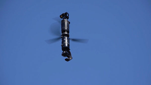
The Spirit dual-rotor coaxial unmanned aerial system (UAS) is a versatile and durable system for mission-critical operations. Combined with a fully modular, plug-and-play payload design, the Spirit’s open architecture allows operators to easily add or upgrade software to unlock new operating capabilities without the need to design or develop a new aircraft. It has an all-weather airframe. With nearly 10 pounds available for batteries and payloads, Spirit sets the new standard for performance in its weight class. Setup is quick and easy, allowing for takeoff from any type of terrain. The highly streamlined all-weather airframe has a top speed of 60 miles per hour and can operate in high winds. Payloads and batteries can be mounted or stacked on the top or bottom point.
When I saw that there was a plan for a whole bunch of unmanned, semi-autonomous racecars to compete at the Indianapolis Motor Speedway (Indy, or IMS) racetrack, I initially thought we might be headed to one significant mess of broken-up machines and potentially a lot of damage. I tracked the various announcements of the competition as things progressed, especially when a prize of $1 million dollars was put up by the Lilly Endowment in Indianapolis, and the majority of the field appeared to be potentially staffed by undergrad university teams.
Photo: Indy Autonomous Challenge
However, this isn’t the first time we’ve had unmanned, autonomous road vehicles in competition — we’ve seen highly instrumented SUVs in desert settings in Nevada and California, initially with pretty poor results, which began to improve significantly for the second time round, then vehicles in some simulated street settings with some mixed and also some pretty good results.
So, as the competition date grew closer for the Indy Autonomous Challenge (IAC), the number of published progress reports began to increase, and we began to better understand how the initial 40 teams might take on this seemingly impossible task — how on Earth will they replicate a regular Indy (also a class of racecar) race? Surely many unmanned racecars on the same track at the same time doing more than 150 mph would be catastrophic!
When you take a look, however, at the advances we’ve seen, which have enabled unmanned cars, trucks, taxis and such – surely this tech could stretch to meet these major objectives? But Dallara AV-21 Indy Light racecars avoiding hurtling walls passing by, cornering, getting in and out of the pits, coping with vehicles behind, ahead and overtaking — even a superior-equipped unmanned racecar at >150 mph — well that’s something we would really need to see.
Then you have to take a look at the outfits involved, providing support to the IAC teams – companies including Cisco, and motor sport units such as ADLINK, Ansys, Aptiv, Bridgestone, Luminar, Microsoft and Valvoline and the non-profit Energy Systems Network. The University teams from around the world themselves appeared to also have significant heritage and skill-levels.
As the 40 University teams started the long trek to get over the hurdles that this challenge presented, members from 21 of those institutions were actually able to make it to Indy, grouped into nine “national” teams. By October 23 the nine teams, with only one car each, were ready to test their autonomous vehicles on the actual track.
Clemson University established the baseline Dallara AV-21 vehicle and technology to be used by each team for the race, with sensors monitoring chassis motion, suspension, tires and powertrain. Each team would install its own guidance and avoidance system, with each vehicle equipped with six cameras, four lidars, RTK GNSS, associated radios and bags of computing running each team’s customized control system software. The object being for cars to exit pit-lane, accelerate, brake, establish an optimum line for each corner and flat, avoid obstacles, evaluate the track conditions and establish tolerable limits.
The teams were required to complete several stages of selection, from submission of initial proposals through demonstration of existing vehicle automation capability, simulated race performance, qualification testing at the Indy track — all leading to an anticipated head-to head race against the other qualifiers.
Then 20 days of planned testing stretched to 50, and three months of preparation passed with students working intensely throughout, curing the glitches, experimenting with how to increase lap speed, and pushing the limits while still keeping the cars intact.
Energy Systems Network managed the rules of the final competition in a way that reflected Indy qualification days prior the main race — they judged that the technology was not yet at a stage where multiple cars on the track at the same time would have been such a good idea. So, each car was to individually run a number of practice/qualification laps and the quickest car would be the winner.
During the first stage of live competition, cars were required to exit the pits and run a warmup lap, followed by two laps that were timed and a slow-down lap that required navigating around inflatable barriers on the front-stretch, and then return successfully back around the track into their pit-stop locations. There were several spins in the corners and several crashes, but the four surviving cars/teams were able to optimistically post speeds of more than 130 mph.
Photo: Indy Autonomous Challenge
The final phase involved the four teams taking their cars around a number of warm-up/practice laps, followed by four timed laps. Only the car from Germany’s Technical University of Munich was able to complete all laps with an average speed of ~136 mph, so that team ultimately won the $1 million prize. Even so, all teams were able to successfully mature their systems’ performance through the many months leading up to the IAC and their progress through the various qualification stages. Even the other three final qualifiers had much to celebrate as a result of the competition.
The sponsors supporting the various teams as they progressed through the Challenge may have spent more than $120 million, so that high-pressure development work will be invested back into many vehicle automation opportunities. After all, that was the main objective for the whole undertaking. We should hopefully begin to see safer, more capable self-driving vehicles emerge in the months to come as the technology is applied to more production vehicle automation.
“What’s new with GPS?” people often ask me when I tell them my job. Recently, I have been responding by telling them about the other three GNSS constellations now fully available. However, as reflected every month in these pages, that is but one of many developments that combine to make satellite navigation ever more accurate, reliable and ubiquitous.
While the GPS program is old by the standards of the digital age, it has never been static. In the 1970s, when GPS was developed, the expected accuracy for civilians was tens of meters, though pioneering commercial users began right away to chip away at the system’s limitations by developing differential GPS (DGPS), carrier-phase positioning, and other techniques. By the end of the next decade, better signal processing and the implementation of DGPS had brought civilian accuracy to about one meter. In the 1990s, phase-ambiguity resolution made real-time centimeter accuracy standard for surveyors.
As the adoption of cell phones exploded, it became imperative to locate them to preserve the 911 system. Initially, this was done using the time-of-arrival of signals to handsets from towers, because it was assumed that GPS receivers could not be made sufficiently small, cheap, fast, power-efficient and accurate to work in cell phones. The implementation of assisted GPS, now standard in all smartphones, largely solved those problems.
Precision for civil GPS users increased by an order of magnitude in May 2000, when President Clinton ordered the removal of Selective Availability, and substantially once enough satellites began to broadcast the L2 civil (L2C) code, enabling ionospheric corrections. Later, the modernized signals in the L5 band enabled sub-meter accuracy without augmentations and very long-range operations with augmentations. There are now more than 80 signals in that band, on GPS, Galileo and BeiDou satellites. On the military side, the effort to deploy M-code signals, cards and receivers continues.
Over the years, in addition to modernized satellites and signals, improvements have included the development of PPP, RTK and hybrid techniques; the proliferation of local, regional and global correction services; improved jamming and spoofing detection; and the increasing integration of GNSS receivers with other RF receivers as well as with inertial, optical, radar, lidar and other sensors.
Future improvements may include:
signal authentication
commercial systems in low Earth orbit that would have a signal strength on the surface three orders of magnitude greater than current GNSS, greatly boosting indoor reception and protection from jamming
inertially aided extended coherent integration, a.k.a. “supercorrelation,” which makes moving GNSS receivers more sensitive to signals they receive directly than to reflected ones
3D-mapping-aided GNSS, which enhances the positioning algorithms by identifying non-line-of-sight signals; this is being pioneered by Google in nearly 4,000 cities, relying on its 3D city models and machine learning.
The moment I send this month’s issue to the printer, I will think of more past and future improvements. As soon as you receive it, many of you will think of yet more. What’s new with GPS? A lot.
The General Lighthouse Authorities (GLA) of the United Kingdom and Ireland has named Alan Grant to the top post of its research and development team. Grant assumed his new role on Nov. 1.
As part of his duties, he heads the GLA’s research and development program, considering existing and future maritime requirements and operational strategy. GLA Research and Development (GRAD) is tasked with improving maritime safety by developing innovative and cost-effective maritime aids-to-navigation (AtoN).
GRAD projects have included all aspects of AtoN including human and machine interaction, operational life and environment. The team has deep technical expertise and experience with automatic identification systems (AIS) , the VHF Data Exchange System (VDES) , eLoran, e‑navigation, GNSS, SBAS and visual signaling.
The organization is well known for its expertise in electronic navigation aids and was an important contributor to the MarRINav project. The project effort was funded by the European Space Agency and examined what combination of electronic aids to navigation are needed to ensure uninterrupted UK shipping.
Grant joined the GLA in 2003 and has worked on a variety of systems during his time with GRAD. He led a series of successful GPS jamming trials and the development of the multi-system radionavigation receiver performance standards, from initial concept to international recognition at the IMO. He continues to support resilient positioning, navigation and timing in maritime navigation at both technical and strategic levels.
Grant is a Fellow of the Royal Institute of Navigation, where he is a member of the council and served as vice president, 2019-2021. He is also a member of the U.S. Institute of Navigation and served on the ION Council, 2013-2017.
Grant chairs the International Association of Marine Aids to Navigation and Lighthouse Authorities (IALA) radionavigation services working group and is a member of several international standards bodies. He is a chartered engineer, a chartered physicist, and author of more than 120 journal papers, magazine articles, and conference papers.
Martin Bransby, the prior GRAD leader, has taken a position with Telespazio in the UK.
Longstone Lighthouse is situated on the Outer Farne Islands on the Northumberland Coast in Northern England. (Photo: ad_foto/iStock/Getty Images Plus/Getty Images)
Chronos Technology Ltd., a UK-based resilient synchronization and timing company, has transitioned to employee ownership through the Chronos Technology Employee Ownership Trust (EOT) Ltd.
Charles Curry who established Chronos Technology in September 1986 and was co-owner alongside his wife, Angela Curry, had been deliberating succession planning and their exit from the business. Various options such as a third-party sale or a management buyout were considered but quickly dismissed.
“I am aware of business owners who had exited through third-party sales and had not enjoyed the experience of working under new management for the agreed handover period,” Curry said. “New owners generally change the dynamic of the business, often introducing new staff and work practice without giving opportunity to existing staff and process, and we did not want this for Chronos.”
“Over the years we have established a work ethic that puts the customer first,” Curry continued. “The EOT protects the loyal Chronos family and ensures the customer-facing continuity of the business and, most importantly, safeguards jobs. Going forward, in the hands of the employees, the company will benefit from increased customer engagement and the commitment to a team approach to steer the business on the next phase of its journey.”
Chronos Technology specializes in resilient synchronization and timing systems, smart technologies, GNSS and cybersecurity solutions for critical national infrastructure, with industry experience gathered over 35 years in specialist technologies such as GNSS, PTP, NTP and SyncE.
The company provides GPS coverage solutions in hangars, manufacturing areas and underground, as well as smart technology solutions and GNSS jamming detection and location solutions for law enforcement. Customers include telecom, finance, energy, data centers, broadcast, aerospace, defence and security, enterprise/IT, emergency services, transport and manufacturing.
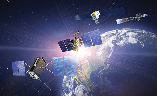
The tremendous benefits of having four complete GNSS constellations
In 2020, with the completion of China’s BeiDou-3 (aka BDS) and Europe’s Galileo, the number of available global navigation satellite system (GNSS) constellations doubled.
Analogously to the addition of GLONASS to GPS a quarter century earlier, but much more so, this sharp increase in the number of available satellites and frequencies greatly improved the precision of satellite-based positioning, the speed of first fix, and the confidence in the results — especially in GNSS-challenged places, such as under thick canopy and in deep urban canyons.
Additionally, this new ability to track three or four GNSS constellations makes the overall positioning solution more resilient to malicious RF interference (jamming and spoofing), to accidental GNSS service disruptions such as Galileo’s one-week service outage in July 2019, and to deliberate withholding of service such as might occur in times of war.
While all this may make little practical difference to a driver needing to know which highway exit to take or to a pedestrian looking for the nearest pharmacy, it is very valuable in high-end applications, such as surveying and construction. In fact, surveyors who have transitioned to using all the available constellations are ecstatic.
This month’s cover story, on the benefits of having four complete GNSS constellations, is in two parts. First, Oliver Montenbruck and Peter Steigenberger discuss “the practical relevance and implications of having four GNSS in parallel for both mass-market and high-end users.” Next, I present the comments of three surveyors and a receiver manufacturer:
Gavin Schrock, PLS, is a practicing land surveyor, the operator of a cooperative real-time GNSS network in Washington state, and a technology writer
James Richards is the senior land and utility surveyor at Benchmark Surveys in Venny Bridge, UK
Choice Sterling is the survey manager at Kiewit Corporation in Federal Way, Washington
Xiaohua Wen is the CEO and founder of Tersus GNSS, a manufacturer of GNSS surveying receivers based in Australia.
(Satellites from left) GPS: In July 1995, GPS achieved full operational capability (FOC). GLONASS: In December 1995, the (then) Soviet system achieved FOC. BeiDou: On June 23, 2020, China launched the final satellite of the BeiDou-3 constellation. Galileo: The constellation has 21 usable satellites.(Credit: Satellites from public sources; background image: NASA/Chaykovsky Igor/Shutterstock.com)
James Richards Senior Land and Utility surveyor Benchmark Surveys, Venny Bridge, UK
James Richards, Benchmark Surveys
What kinds of surveying projects do you run?
We run many different types of surveying projects. From small single-story bungalow extensions and redevelopment to development of new home sites of several hundred acres. We cover land, underground utility, and measured-building surveys of any size project, using the latest equipment in total stations, laser scanners, drones, GPS receivers, ground-penetrating radar (GPR) and electromagnetic location (EML).
How have you transitioned to using multiple constellations?
Ordnance Survey benchmarks in the UK are no longer maintained. Therefore, it has been a must to move forward with the surveying world and use multi-constellation GNSS equipment. We have stayed at the forefront of GNSS receivers, starting with a Topcon GRS1 then moving onto a Trimble R10 and a Topcon HiPer SR. Now, I feel we’ve taken another leap with the Trimble R12i, working in areas where we previously did not even consider using a GNSS receiver.
How does the availability of four complete GNSS constellations, plus two regional ones, benefit your work?
The availability of four complete GNSS constellations and two regional ones gives us more reliability as well as improved position and time accuracy in the data that we receive. It also gives us better coverage over the entire UK, including near buildings and under foliage. The Trimble R12i has 672 available channels, which makes it future-proof to new frequencies and additional space vehicles.
Choice Sterling Survey manager, Kiewit Corporation Federal Way, Washington
What kinds of surveying projects do you run?
I am the survey manager on $1–3 billion mega projects, ranging from bridges and highways to tunnels and rail, including a couple of projects for the U.S. Department of Defense.
How have you transitioned to using multiple constellations?
The use of multiple constellations became available as we adopted technologies that could capitalize on their availability. Through the latest hardware and software, we have begun leveraging GNSS to a greater magnitude than we would have just a few years back.
How does the availability of four complete GNSS constellations, plus two regional ones, benefit your work?
Not long ago, the use of GPS for construction staking was an extremely risky proposition given its unreliability, primarily in the vertical component, and lack of confidence in its horizontal accuracy. With residuals exceeding most construction tolerances, GPS was primarily utilized for earthwork or to establish geodetic pairs that could then be traversed to establish control for more precise work. With the utilization of multiple GNSS constellations, we have gained confidence in the accuracy of our results and have started leveraging GPS for construction staking where we were once not willing to take the risk.
Having the ability to leverage GPS under a canopy of trees or against structures or walls has proved invaluable when running traverses or levels, typically enabling us to use a single person rather than a two-person crew. Increased confidence in repeatability and accuracy while using GPS has been a game changer when working on projects where efficiency and cost management are of the greatest importance.
How have you transitioned to manufacturing multiple-constellation GNSS receivers?
Early in 2016, we produced a GNSS receiver evolution road map to take advantage of GPS/GLONASS modernization, the continuing development of Galileo and QZSS, and the completion of BeiDou-3. In 2019, we released our current GNSS receiver, which has 576 tracking channels and supports all five major GNSS constellations (GPS, GLONASS, Galileo, BeiDou-3 and QZSS) and triple-band broadcasts (GPS L1+L2C+L2P+L5, GLO G1+G2+G3, GAL E1+E5a+E5b, BDS B1+B2a+B2b and QZSS L1+L2C+L5). We expect to release our next generation receiver, with 832 channels, in February 2022. It will support all available constellations (GPS, GLO, GAL, BDS, QZSS, IRNSS/NavIC, SBAS) and all civil signals, including the AltBoc and AceBoc.
How does the availability of four complete GNSS constellations, plus two regional ones, benefit your end users?
The most significant advantage of modern GNSS receivers is their robust high-accuracy performance with the aiding of the new constellations and signals, especially in harsh GNSS environments, such as deep canyons and heavy foliage. It greatly extended the RTK fix capability, and now reliable GNSS RTK fix solutions can be easily achieved in areas where it was impossible to do in the past.
In the past, multipath always has been a problem for RTK GNSS receivers, as it might cause blunder errors. The improved RTK fix reliability based on robust RTK integrity monitoring takes advantage of the redundancy of observations to identify and isolate deteriorated observations and confirm the fixed result. Additionally, RTK achieves RTK fix solutions faster and maintains the RTK fix solutions easier with better accuracy than before.
Compared to the dual-band (L1+L2) of GPS plus GLONASS, the triple-band (and multi-band) can allow long-range RTK capability, which can provide reliable RTK solutions with a remote GNSS base station far from the 20–30 km base and rover separation of the past. It also will provide more confidence in RTK positioning during the coming ionospheric disturbance peak in 2023.