South Korea issued a warning Thursday after detecting satellite signal disruptions that appeared to be coming from North Korea, according to the Korea Herald. The capital city of Seoul appeared to be the target.
Officials said North Korea discharged a large amount of radio waves to jam GPS signals in the region.
“We’ve detected signs that North Korea has been sending radio waves to the capital area since a month ago to disrupt GPS signals,” a senior government official said, speaking on condition of anonymity. “North Korea had been sending test waves since last month, but today, they discharged the largest amount.”
The warning was issued at 7:30 p.m. in Seoul, the adjacent city of Incheon and the surrounding Gyeonggi and Gangwon provinces.
The disruptions could cause mobile phones to malfunction and affect planes and ships that rely on GPS for navigation. No damage has so far been reported in the military or among civilians, officials said.
Since 2010, GPS disruptions have occurred three times in South Korea, and all have been blamed on the North.
The GPS modernization funding picture cannot be called bright, yet neither can it be characterized as dim. While big money for big projects appears hard to come by, the U.S. government and military offer many smaller allocations to help fill the chinks in GPS armor. Such initiatives concern jamming, PNT solutions in GPS-denied environments and other conundrums. A run of Small Business Innovation Research (SBIR) requests for proposals have appeared recently.
A caveat: the U.S. government has some history of soliciting innovation from small firms, then awarding continuation of the work to big, established government contractors, under the rationale that these companies have capacity to carry out large-scale manufacturing.
The current batch of RFPs specify Phase I contracts that will, by statute, all go to small businesses, as will Phase II. The problem then — for these contract winners —is that follow-on work typically goes to large primes.
Jamming. The objective of a tender issued in December of last year, with a closing date of Feb. 17, is to “develop a ground-based GNSS Jammer Location capability utilizing a single GNSS receiver capable of estimating the position of a GNSS jammer within 100 meters, and estimating jammer position within 10 meters when networked with other sensors.”
The Department of Defense (DoD) continues: “Although many effective techniques exist, they primarily rely on airborne equipment, using either high demand, low density assets or dedicated aircraft such as unmanned aerial vehicles (UAVs). To enhance the future Navwar capabilities of DoD, a ground-based capability that can operate in urban canyons or mountainous terrain will provide a significant improvement to overarching Navwar capability. In some cases, jammers may be deployed on mobile ground vehicles in an urban environment, making them difficult to detect and track.”
DoD wants you to exploit opportunities offered by multipath and controlled radiation pattern antennas (CRPAs) to detect and locate 100-watt mobile jammers.
“Four alternatives should be evaluated: 1) a single GNSS receiver without a CRPA, 2) a single GNSS receiver with a CRPA, 3) two or more networked receivers without a CRPA, and 4) two or more GNSS receivers with a CRPA. For each alternative, assess the location accuracy, cost (both recurring and nonrecurring), and suitability for integrating in a ground vehicle.”
The DoD also offers stimulus funding for a range of other problems seeking a solution. The closing date is Feb. 17 for all of these, so sharpen your pencils and put on your thinking caps.
Contracts and Future Work. Concerning the follow-on work issue, Alison Brown, Co-Chair of the Government Contracting Working Group in the Small Business Administration’s (SBA’s) Regulatory Fairness Board, has written a white paper, “SBIR Regulatory Enforcement Issues,” available here. In it, she reviews the degree to which DoD complies with existing law. Congress has enacted Sec. 5108, mandating that “To the greatest extent practicable, Federal agencies and Federal prime contractors shall issue Phase III awards relating to technology, including sole source awards, to the SBIR and STTR award recipients that developed the technology.”
Brown states that “currently there is no effective recourse for small businesses or avenues for enforcement of the current SBIR Regulations within the DOD and other government agencies.” She recounts in the paper her own experience, as founder and CEO of NAVSYS Corporation.
NAVSYS developed and fielded a precision GPS navigation capability, Talon NAMATH, under a Phase III SBIR contract to Air Force Tactical Exploitation of National Capabilities (TENCAP). The systems was declared “provisionally operational” and used in theater in Operation Iraqi Freedom. Although the Talon NAMATH system was declared a huge success in theater, the follow-on contract for a fully operational system was awarded to Boeing.
Brown is also a longtime member of GPS World’s Editorial Advisory Board.
The U.S. Coast Guard issued a safety alert on Jan. 16, warning mariners of the potential detrimental impact to navigation caused by GPS interference or jamming. The warning emphasizes the importance of understanding how vessel equipment could be impacted by the loss of a GPS signal.
The Coast Guard states that this past summer, multiple outbound vessels from a non-U.S. port suddenly lost GPS signal reception. The net effect was various alarms and a loss of GPS input to the ship’s surface search radar, gyro units and ECDIS, resulting in no GPS data for position fixing, radar over ground speed inputs, gyro speed input and loss of collision avoidance capabilities on the radar display.
Fortunately, the vessels were able to safely continue theirvoyage using radar in heads up display, magnetic compass and terrestrial navigation. Approximately six nautical miles later, the vessels’ GPS units resumed operation. Although the vessels had back-up systems to allow a safe transit, the consequences could have been severe, warns the Coast Guard.
Full content of the alert appears below.
Global Navigation Satellite Systems – Trust, But Verify Report Disruptions Immediately
Do you know what equipment relies upon the U.S. Global Positioning System (GPS) signal? How would you respond if you lost the signal? This past summer, multiple outbound vessels from a non-U.S. port suddenly lost GPS signal reception. The net effect was various alarms and a loss of GPS input to the ship’s surface search radar, gyro units and Electronic Chart Display & Information System (ECDIS), resulting in no GPS data for position fixing, radar over ground speed inputs, gyro speed input and loss of collision avoidance capabilities on the radar display. Fortunately, the vessels were able to safely continue their voyage using radar in heads up display, magnetic compass and terrestrial navigation. Approximately 6nm later, the vessels’ GPS units resumed operation. Although the vessels had back-up systems to allow a safe transit, the consequences could have been severe. These types of events highlight the potential detrimental impact to navigation caused by GPS interference or jamming and the importance in understanding how your vessel’s or facility’s equipment could be impacted by a loss of GPS signal.
Whether walking through the city, driving across town or navigating the world, Global Navigation Satellite Systems (GNSS) have become an integral part of everyday life. However, at times, the positioning signals may be impacted by interference from both natural and human-made sources. The most common types of interference are reception issues, usually due to bad installations, poor antenna positioning or faulty equipment. Jamming devices, while illegal in the U.S. and a threat to safety, have been used for nefarious or deceptive purposes. Interference can also be unintentionally caused when operating GNSS in close proximity to other radiating devices, such as amplified TV antennas (see our Safety Alert 11-02). Therefore, it is important to remember to use all available means for navigation and maintain proficiency so you can still navigate should your primary GPS fail.
Indicators of positioning systems interference include an intermittent signal, no signal, or an incorrect signal. Suspected or suspicious disruptions should be reported immediately. Critical information to take note of during a disruption event includes location, time, and period of outage.
Commercial operators are reminded, should your navigation or other equipment onboard (e.g. AIS) be impaired as a result of a disruption or interference, this should be reported to the nearest U.S. Coast Guard Captain of the Port, District Commander or Vessel Traffic Center as soon as possible; and, await further directions (per 33 CFR 164.53).
All operators should be aware, vigilant, and immediately report GPS disruptions to the U.S. Coast Guard Navigation Center (NAVCEN). The report will be disseminated to the U.S. Air Force GPS Operations Center and the Federal Aviation Administration in an attempt to identify the problem and correlate with any other GPS incidents in the same general geographic location. Depending on the severity of the report, NAVCEN may refer it to law enforcement and/or other federal agencies for further investigation.
Reporting a disruption — or other navigation hazards or aids to navigation outages — is simple, and can be done electronically (http://www.navcen.uscg.gov, the preferred method) or via phone call to the NAVCEN (703- 313-5900), 24 hours a day.
Wavelet Packet Decomposition (WPD) shows promise as an anti-jamming tool.
The WPD is derived from the wavelet transform, which provides a representation of the signal components in a domain spanned by a set of functions that can be seen as band-pass filters with a bandwidth decreasing as their central frequency increases, thus granting a uniform resolution in the decomposition of the signal under analysis.
A paper by Luciano Musumeci and Fabio Dovis of Politecnico di Torino and James T. Curran of the Joint European Commission’s Research Center, titled “A Comparative Analysis of Adaptive Notch Filtering and Wavelet Mitigation against Jammers Interference,” won the Best Paper in Session award in GNSS Vulnerabilities and Anti-Jamming at the ION-GNSS+ 2015 conference.
The paper compares two interference mitigation techniques at the digital signal processing level for jamming signal removal.
The authors compare the traditional adaptive notch filtering scheme, widely discussed in scientific literature, with a new technique based on the use of the WPD. Both techniques are implemented in software, and their performance has been assessed via the use of a fully software GNSS receiver. Both techniques are first applied to a set of simulated GNSS jammed scenarios.
Preliminary results demonstrate that a significant improvement is achieved at both acquisition and tracking level when the WPD algorithm is employed with respect to the application of the classical adaptive notch filtering. In fact, using the adaptive notch filtering, the effective range of the jamming can be reduced from approximately 474 meters up to 127 meters, while when using the WPD-based algorithm, such a range can be further reduced up to approximately 10 meters. These results are also confirmed by successive test campaigns where performance comparison of both software implemented techniques is assessed considering simulated GNSS data.
The WPD-based technique is characterized by a higher computational complexity with respect to the implementation of notch filtering. This is mainly caused by the several filtering operations needed for the time-scale representation computation. Therefore, the number of decomposition stages and the filter length need to be carefully traded off with the jamming detection and removal capability of such a technique.
However, the availability of a high-performing processor together with a jamming detection based on spectral estimation can potentially lead to a faster WPD computation for future real-time applications.
That is, in the People’s Republic of Boulder, Colorado. To those of us who live in Colorado, Boulder is known by this seemingly timeless but absolutely accurate appellation. This stunningly beautiful city located in the foothills of the Rocky Mountains, known as the Flatirons, is where the National Space-Based Positioning, Navigation and Timing Advisory Board (PNTAB), which provides independent advice to the National Executive Committee on Space-Based PNT (EXCOM) from outside the U.S. government, chose to meet in the waning days of October 2015. Ironically, they chose the same week as a Republican presidential candidates debate, which took place at the University of Colorado just a couple of miles away. The PNTAB was also concomitant with the ICG, the Tenth Meeting of the International Committee on GNSS (ICG-10), held Nov. 2-5, 2015. Both the PNTAB and ICG were held at the Boulder NCAR/UCAR facility, University Corporation for Atmospheric Research Center Green Conference facility.
PNTAB
The PNTAB serves a vital purpose. Board memberse advise the highest levels of the U.S. government (USG) concerning all matters relating to PNT. This open-ended charter covers a multitude of sins, and as the new PNTAB Chairman John Stenbit, stated clearly, it is important to focus on the doable, even if it seems difficult, but not to tilt at windmills. I have known and worked with John Stenbit for more than 25 years, especially during his two stints in the Pentagon, and I find him to be extremely knowledgeable and ethical. He is certainly well-spoken and gregarious, but he does not suffer fools, and is known to be resolute, which is a pseudonym for stubborn and hardheaded, but in a good way. I look forward to his chairmanship.
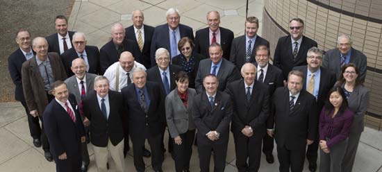
PNTAB Members at 16th Meeting in Boulder. New Chairman John Stenbit is center of last row. (Courtesy of gps.gov)
You can view the PNTAB presentations at the www.gps.gov website. While there, you will note there were more than 25 presentations, and most were excellent. Only a couple required the audience to consume copious amounts of caffeine to remain coherent.
In the end, the PNTAB adopted courses of action (COA) on which to formulate recommendations for the EXCOM. For our purposes, the pertinent COAs centered around two main subject areas: Spectrum protection and eLoran. The spectrum protection issues are fraught with equal parts litigious danger and tedium. Not coincidently, the World Radiocommunication Conference 2015 (WRC-15) kicked off in Geneva, Switzerland, on Nov. 2, just two days after the end of the PNTAB. Several of the PNTAB members attended the closing Saturday night PNTAB dinner and flew from Denver direct to Geneva Sunday morning, just in time for some minor jet lag adjustments, and then attended the opening ceremonies of WRC 2015 in snowy Switzerland.
I have had the dubious privilege of observing several International Telecommunication Union (ITU)-sponsored WRC sessions in the past, and it is certainly a critical spectrum decision-making body. (Seriously, folks, 26 days of talking and wrangling about spectrum? Praise the Lord the Swiss know how to brew strong coffee.) WRC 2015 wraps up on Nov. 27. In this regard, Ann Ciganer, who serves as an official PNTAB representative and the executive director of policy for the GPS Innovation Alliance (GPSIA, formerly the U.S. GPS Industry Council), is my hero. She has been working spectrum issues for more than 20 years. She has the fortitude of FDR and the patience of Job.
Since the spectrum and spectrum-protection issues are still being coldly debated in Geneva, let’s take a look at the PNTAB’s second major topic, eLoran. While eLoran was discussed ad nauseam, there was one definitive standout presentation given by my old friend and colleague Professor David Last. David is Professor Emeritus at the University of Wales (Bangor) and former president of the Royal Institute of Navigation (RIN). As he is wont to do, David held forth, with that wonderful, attention-arresting British public school accent, on eLoran matters before an appreciative audience. David presented his topic with equal parts passion and credibility. You can view his presentation material in its entirety (the PowerPoint slides, anyway) at www.gps.gov, but you will not have the wonderful experience of having him present it personally with all the attendant persuasion, and dry British humor and wit.
eLoran European Style
David immediately makes the point early on in the historical portion of his presentation that the U.S. first committed to Loran-C more than 75 years ago, and as recently as 2010 upgraded a majority of the sites to eLoran status only to have the current administration shut down Loran just after officially assuring the United Kingdom the U.S. would keep Loran up and running. Now the U.S. is in the position of looking for a backup and major terrestrial augmentation to GPS (GNSS) and is once again considering eLoran.
Professor David Last at 16th PNTAB
Professor David Last at the 16th PNTAB meeting. (Photo: Don Jewell)
Professor Last explained the difference between our viewpoints. “I see it from a British perspective, and a European perspective. I watch administrations in other parts of the world grappling with the same decisions the U.S. faces. The U.S., of course, is in a unique position: it is the source of GPS, the world standard in satellite navigation. And over the nearly 40 years since the first satellite was launched, the U.S. has taken the lead in learning to understand the role of GPS, from its military-only origins, through when it was a novelty with its first civil applications, through a period of hubris in which it was to replace every other means of navigation on land, sea and air, to its present role, so deeply embedded in your national life as to form a critical component of national infrastructure. The U.S. was first to recognize the vulnerabilities of GPS, to understand the threat they posed to your nation and to seek ways of mitigating them. That topic came to dominate technical conferences first in the U.S. and now around the world. And it has led to a policy debate of quite exceptional difficulty, one that is shared by all governments.”
The Message
What David did not come right out and say, although I maintain it was implied by his tone of voice and body language, is that this discussion is at times both energized and denigrated by those that refuse to acknowledge GPS or GNSS vulnerabilities and those that would be happy to see it revert to a military-only system — the proverbial ostrich syndrome. David made it clear that GPS vulnerability discussions must take place publicly in the U.S. because they are, in fact, global discussions. “All space-based PNT systems today are similar to GPS in concept and technology, and referred to by most users as GPS,” he said. “Very few bother or even know about Galileo, GLONASS and BeiDou. To them, it is all simply GPS.”
David went on to make his point by describing the ubiquity and pervasiveness of GPS and GNSS. “Now there is no area of transportation, commerce, industry or telecommunications in your country or mine that does not employ satellite navigation.”
Indeed, David described how other GNSS systems came about due to national pride, and yet they had no choice but to mimic GPS both technically and officially, since they must for safety-of-life concerns reside in the same regimes and crowded radio bands.
David stated, “Soon, these new GNSS became invested with immense national pride. Their vast cost had to be justified by claims of technical superiority. In reality, engineers know that their designers had no choice but to make them compatible with GPS, since GPS was decades ahead and the world standard. These new systems also had to squeeze alongside GPS in the narrow radio bands allocated internationally to navigation. Not surprisingly, indeed happily, all our new GNSS turned out to look very like GPS: versions of the same technology — with just a hint of garlic here, a whiff of curry there. This similarity is obvious to engineers and to navigators, though rarely to politicians.”
DOT Volpe GPS Jamming Report
Professor Last referred to the U.S. provider and user communities as groups that, prior to the important 2001 Volpe Report, failed to acknowledge that GPS had any serious vulnerabilities. That report was a watershed event for the future of GPS, and for me as a journalist. Among other jamming incidents around the country, a major jamming occurrence in San Diego harbor affected GPS-dependent systems (mostly those dependent on accurate timing) and users for miles around. It became a wakeup call for GPS and GNSS users globally; I wrote a Defense PNT column on it in this space in 2007.
David put it in perspective. “To understand the perceptions of those governments, wind back the U.S. story to before the Volpe Report on GPS vulnerability with its recommendations that led to your [PNT Advisory] Board’s policy of ‘Protect, Toughen, and Augment’. Despite the growth of jamming and even attacks by one sovereign nation on its neighbor, despite the appearance of low-cost spoofing, there has never been a Volpe Report anywhere outside the United States. The pre-Volpe culture of the denial of vulnerability is alive and well and living in Europe.”
“Thirty-seven years after the launch of the first GPS satellite, there is still little recognition by the world’s governments of how essential resilient position, navigation and timing have become to the critical infrastructure of their nations,” Last said.
After the Volpe Report came an industry report chaired by the Father of GPS, Professor Bradford Parkinson (Col, USAF, Ret), describing eLoran as the only cost-effective method of backup to GPS. The report was published globally, and then the United States completely failed to implement the transition from Loran-C to eLoran. At the time it failed politically, the Loran-C to eLoran conversion was 85 percent complete and only needed a small amount of funding for the future. Luddites within the U.S. OMB (Office of Management and Budget) managed to kill the program just short of completion. Unfortunately, the message to the world of GPS users was the U.S. had categorically rejected eLoran as a complimentary PNT system.
David presented the European point of view: “The Volpe Report, an FAA study, proposed and demonstrated Enhanced Loran (eLoran). GPS-like digital techniques were applied to the obsolete Loran-C low-frequency system. The result were astounding: it met the accuracy, integrity, availability and continuity standards of certain aircraft instrument approaches plus the very demanding port-entrance requirements of shipping, and it delivered precise timing to support telecomms. Brad Parkinson’s high-level study group of industry leaders said this was the only cost-effective GPS substitute for U.S. needs.
“The world outside the U.S. watched the Department of Homeland Security announce eLoran as the U.S. national backup to GPS and then completely fail to implement it! That message, that the U.S. does not need a complementary system and has rejected eLoran, is the current understanding of U.S. policy in many countries.”
Professor Last maintains the same eLoran drama is now being played out in Europe in real time. The UK developed its own eLoran system from the North of Norway to the South of France which, while it only officially achieved initial operational capability on Oct 31, 2014, has in fact been running flawlessly 24/7 for three years.
The message to the world, especially Europe, should be that the eLoran concept proposed by the U.S. FAA (Federal Aviation Administration) really works and is easy to implement. It has been, in fact, implemented and maintained in the UK by a mere handful of personnel.
However, according to David, the European eLoran system may never reach FOC (full operational capability) because currently Western Europe lacks any coordinated plan to respond to the vulnerabilities of GPS and all other PNT systems. Many have yet to embrace or even recognize the Volpe Report.
Indeed, several European countries are planning to shut down their eLoran systems supposedly since that is what we (the U.S.) did and it seems to be working for us.
David explains that “this [proven] system may never reach Full Operational Capability. Western Europe lacks any coordinated plan to respond to the vulnerability of GPS — why, who needs that when Europe has Galileo and EGNOS! The governments who control the Loran stations in Norway and France, observing that mariners no longer want Loran-C, plan to close down the transmissions just nine weeks from now, and demolish the infrastructure. After all, they say, that is what the U.S. did.”
Service Alternative
To paraphrase Winston Churchill, this was indeed not our finest hour. However David maintains there is a realistic commercial alternative: provide eLoran as a service. This is exactly what some in the United Kingdom and Europe are considering. It is a totally viable alternative, but David asserts that what would really help “is a positive signal from the United States.”
Continuing in the same vein, David posits “all is not lost. Responding to the future — indeed, the present — needs of the telecomms and broadcasting industries, and driven from the U.S., there is a commercial plan to take over and operate that European Loran infrastructure and sell its services to government and industrial users. If governments struggle to seize the initiative in this area, let the market — and good old greed — provide the mechanism for realizing the multiple benefits, paying the costs and making a profit. But I believe that this initiative will only succeed in Europe, if there is a positive signal from the U.S. The world listens to signals from the U.S., from the EXCOM, from this board.”
Unique Organizations
Historically, relationships between multi-GNSS systems are confrontational at best; however, David states clearly that Europeans realize the PNTAB and EXCOM are unique and unprecedented around the world. “These official government entities recognize and advocate for resilient PNT that is of major importance to critical infrastructures of the U.S. and other nations as well.”
In actuality, the U.S. has faced up to these vulnerabilities thanks to the PNTAB and EXCOM, two truly unique organizations. Undeniably, there is an incalculable polyphonic argument to be made concerning the vulnerabilities of space-based PNT systems such as GPS and how to mitigate them, but globally beyond the PNTAB and EXCOM, no one is officially having these critical discussions.
In the end, according to Professor Last, over the next nine weeks the immediate future of PNT really comes down to one critical question: “Will global PNT with eLoran be a global system or a nationally unique system?”
David supports his cogent argument for eLoran by giving excellent examples of GPS and multi-GNSS jamming supporting his insightful adage, “Space-based PNT systems live and die together.” They are all subject to the same vulnerabilities.
Wrapping up his refreshingly insightful presentation, Professor Last posed two questions to the PNTAB:
Does the U.S. see a role for eLoran as a complement to resilient GPS?
Does the U.S. recognize and encourage the move to GNSS receivers that take advantage of multiple constellations?
As one PNTAB pundit opined, “The critical issue for the U.S. government is we have to break the mold. The current administration is too often technologically controlled by Luddites and held hostage by low-level bureaucrats within OMB.”
Professor Last appropriately has the last word: “The bottom line for the PNTAB, EXCOM and USG is that the United Kingdom, nee Europe, is asking for support on eLoran.”
Until next time, happy navigating and don’t forget your GPS when you head over the bridge and through the woods to Grandma’s house. Happy Thanksgiving!
The ION GNSS+ 2015 Conference once again fielded a jam-packed agenda of papers on subjects from world-wide constellation updates, through GNSS integrity, indoor navigation demonstrations, multi-constellation/function chipsets, interference mitigation and jamming detection, privacy issues, and many other very interesting subjects. That’s GNSS+ in the conference name, as in “plus,” denoting the many other positioning, navigation, and timing technologies it covers.
Most papers contained advanced academic research, but there were also several new industrial releases. This year ION divided and clearly differentiated sessions between “System and Application Tracks,” that is, those with more direct industry content, and “Peer-Reviewed Tracks,” the so-called “pure” research.
As always, some of the most valuable takeaways of attending ION come from the numerous unrelated, off-the-record corridor conversations: an essential element, always spontaneous and much anticipated, but something that cannot be clearly identified nor put into the program.
The conference seemed to have around the same number attendees as last year with about the same number of exhibitors, even though a few of the big booths were missing. Paradoxically, some exhibitors privately said they did better and more business this year, even with fewer attendees, according to their estimates.
SPIRIT Navigation from Moscow did not have a booth, but Ruslan Budnik made sure to fill my notepad with lots about their technology, products and initiatives. They are among several companies working to add indoor navigation capability to smartphones, using existing onboard sensors and new intelligent software. Their solution concurrently uses multiple technologies including geomagnetic fingerprinting, pedestrian dead reckoning, and map matching, but does not rely on an installed beacon infrastructure. A Spirit app allows store operators to quickly map Wi-Fi and Bluetooth signals and collect a Magnetic field map which matches the floor plan of the store’s venue. Spirit claims an accuracy of around 1 meter, which Ruslan proceeded to demonstrate to me in the corridors around the ION meeting rooms.
Theplenary session on Tuesday night was very interesting with a presentation on the results of NASA’s planetary exploration over the last several decades, by Dr. James Green, NASA Director or Planetary Science. I learned a lot about our solar system; much more out there than one suspects, and much to be revealed in the next few years!
GPS World editor Alan Cameron once again led a preview of the planned sessions for the week, with each session chair constrained to a 5-minute rapid-fire presentation aimed at enticing as many attendees as possible. Interesting and somewhat humorous at the same time; we still got a flavor of what was to come in each track.
On Wednesday I was fortunate to be able to interview several show exhibitors. Some of these you will also find in video footage on the magazine’s website, speaking to you straight from the show floor.
Skydel is a relatively new exhibitor, working with Averna, both from Montreal, Canada. Averna makes signal analysis hardware on which Skydel installs software-based simulation of GNSS signals. Skydel’s objective is to be able to make their solution so affordable that every engineer could have one of these record and playback simulators on their desk, rather than having to schedule time on a central, shared multi-function simulator. An exciting new-entry product developed by an energetic group of people with a high level of ingenuity; hopefully they will succeed.
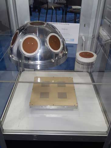
DLR antenna prototypes
A robust receiver initiative from Deutsche Zentrum für Luft- und Raumfahrt (DLR), the German Aerospace Center, aims to demonstrate that jamming and interference detection and mitigation can be achieved much more effectively than just at the RF level. Their processing goes deeper with such features as knowing that a source from a particular direction isn’t aligned with the current constellation, so it’s a jamming/interference suspect. Their conformal antenna development attempts to meld an antenna configuration with their signal processing capabilities. DLR is looking for partners to put these developments into commercial receiver applications.
ComNav has a new K700 family of receivers: K-700 GPS L1, Beidou B1 and Glonass L1 80 channel receiver — added to their K-708 dual frequency 198-channel dual-frequency version. The M300 Pro GNSS Receiver package includes a weather-hardened package, multiple interfaces which enable remote internet control and data access, memory and a rechargeable back-up power supply. ComNav claim the M300 Pro has been selected for the Chinese CORS network. ComNav also anticipates a name change in the near future: SinoGNSS will be their new company name.
Harxon antennas and radiosUnicore UB370 Beidou/GPS/Glonass multi-frequency OEM receiver
Harxon gave us an overview of their wide range of antenna and radio products, while Unicore in the next booth described their single and dual frequency receivers which they are now promoting extensively in North America.
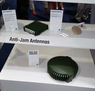
NovAtel GAJT antijam systems
As usual, NovAtel had a wide range of products on display. I was impressed that the mil-spec GAJT anti-jam product-line has now undergone testing by both the U.S. and Canadian military, and that the GAJT-AE is now flying and providing guidance protection in hostile jamming environments. Once again there were mentions of NovAtel receivers and antennas being used for research in several technical papers at the conference.
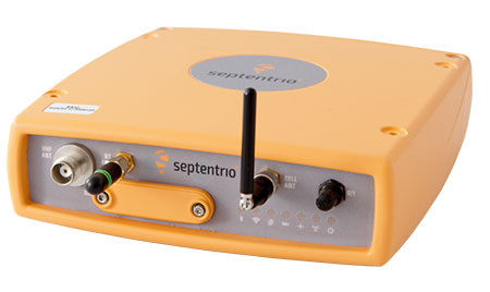
Septentrio continues to make further inroads into the high-precision GNSS receiver market, and announced several new key initiatives. The company has been selected by UNAVCO as the Geodesy Advancing Geosciences and EarthScope (GAGE) facility preferred vendor for next-generation GNSS reference station products. UNAVCO ( ) is a non-profit university-governed consortium, facilitating geoscience research and education using geodesy.
AsteRx-U dual antenna receiver
Septentrio is developing a next-generation reference receiver with UNAVCO’s inputs and evaluation feedback for the purpose of upgrading and renewing their GNSS networks. Septentrio also launched the AsteRx-U and the AsteRx-U Marine multi-constellation dual antenna receivers which incorporate the latest GNSS tracking and positioning algorithms and interference mitigation along with integrated UHF radio, Wi-Fi, USB, Bluetooth, cellular connectivity, and a spectrum analyzer which provides users with their interference profile.
Indoor Navigation
ION’s annual Indoor Navigation Demo session on Wednesday afternoon turned out to have more slides and pre-recorded testing content than actual demonstrations. The participants included Nokia HERE, Rx Networks, SPIRIT Navigation, TRX Systems, Broadcom, Indoors and Combain.
HERE was able to initially demonstrate some indoor tracking of an equipped cellphone, but the display for the audience appeared to quit after a short period. They did provide a link to allow attendees to download their software and try it for themselves.
Rx Networks is apparently focusing on self-location for indoor guidance assets, and ran a pre-recorded demo of ‘Zed’ in a Vancouver Mall – but the vertical tracking display part of the video was completely washed out for the audience.
SPIRIT Navigation ran a recording of the demo I had witnessed earlier – a quite effective, working indoor nav application on a smartphone – and then walked around the demo room, but wasn’t able to show real-time results.
TRX Systems ran a very effective real-time demo and was able to show the audience the path of their ‘walker’ as he meandered around the Conference Center, changed levels and eventually returned on cue to the demo room. They use crowd sourcing to build an initial map which then constrains sensor data from standard sensors, similar to several other presenters. This appeared to be the winning demonstration for this year’s indoor nav demo. We did hear later that they were not using sensors within the smartphone, rather a separate TRX device attached to the belt or the ‘walker’.
Broadcom ran an effective demo, albeit with considerable lag between actual and displayed position and frequent jumps between points, presumably due to the same delay problem. This was attributed to the display system used to present to the audience. They also ran a second short in-room demo which was more effective and more real-time, but apparently not as accurate as TRX from the displayed results.
Indoors also use ‘radio’ fingerprinting with GNSS data as a back-up, and Wi-Fi, BLE, magnetic and inertial data fusion along with dead-reckoning. Their recorded demo was quite effective.
Combain has a system which is required to be world-wide interoperable for machine-to-machine asset location, so they are focused on using cell and Wi-Fi IDs for navigation, with databases containing 64 million Cell IDs and 726 million Wi-Fi location IDs. They claimed accuracies of 200 meters for urban areas and 40 meters for rural. These accuracies are not suitable for indoor location so no demonstration was provided.
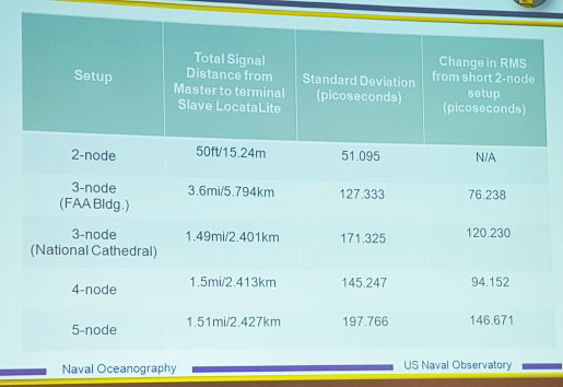
Pico-second test results (Click on the image to enlarge it.)Pico-second test results
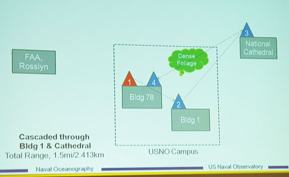
Later, I managed to catch a paper which Locata had recommended, which involved a number of Locata networks used by the U.S. Naval Observatory to demonstrate time and frequency transfer using the USNO Time Standard, with some highly accurate results: picoseconds! This paper forms the basis of GPS World magazine’s October cover story, providing more on these significant time-transfer and synchronization findings.
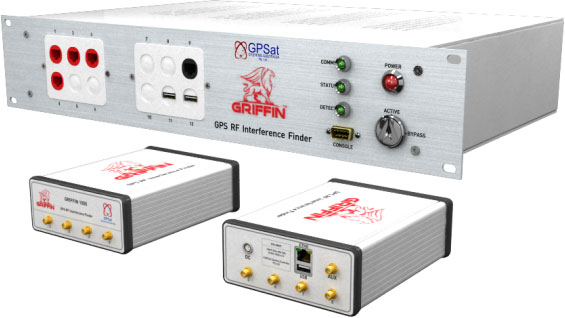
GRIFFIN Central Processor & Node Antenna Electronic Units
Another significant paper was presented in the Interference & Spectrum issues track. GPSat Systems Australia has been working for some time to implement a jammer/interference detection and localization system. The GRIFFIN 1000 system uses both Angle of Arrival (AoA) and Time Difference of Arrival (TDOA) to locate interference sources. GPSat claims that RF interference source in the GPS L1 band can be detected and geo-located to accuracies of a few meters within a few seconds. The system is already in production, with final production field testing underway, and customer deliveries scheduled for November.
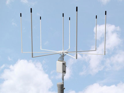
Multi Element Antenna Array and Node Electronics
As ION GNSS+ came to a close for another year, it appears that this GNSS-centric conference is weathering the industry’s apparent preference for other sector shows which may draw new paying customers. ION’s academic/technical content was top-notch as usual, unparalleled anywhere, with attendees flocking to the papers, while existing customers still found comfort in meeting their suppliers on the show floor and around the corridors of the Conference Center. The formula still seems to work for now, but the apparent feeling on the floor was that better exhibitor payback may be found elsewhere, and that this could reduce ION participants in future years. Hopefully not, since this was a very good week for everyone with whom I talked.
Technology Advancement Group (TAG) will be showcasing precision, navigation and timing technology integration solutions at the ION GNSS+ conference, which will be held Sept. 14-15 in Tampa, Fla.
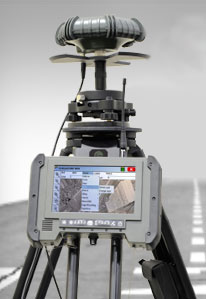
In particular, TAG will display a custom-designed military GNSS survey system that is the U.S. Army program of record for geodetic, construction and airfield surveying.
TAG’s Precise Positioning Service Global Positioning System Survey (PPS GPS-S) system was designed specifically for use by survey teams to have access to centimeter-level GPS survey accuracy with the added benefits of a fully-certified military GPS receiver that is supplemented with a GNSS receiver for real-time kinematic surveying with multi-constellation operations.
The PPS GPS-S system has been specifically designed to address the stringent requirements of military survey missions including geodetic, construction, airfield, and field artillery survey. It gives the military surveyor the tools they need to complete their missions with minimum time-on-station even in the face of GPS signal interference, attempted spoofing, or electronic warfare, the company said.
TAG was recently awarded a $24 million contract by the U.S. Army Geospatial Center for its AN/GSN-16 military survey system.
Core components of the PPS GPS-S system include a base station and two rovers, each integrated with a GNSS antenna with protection against jamming or spoofing, a custom-designed rugged tablet with an internal RF radio that has a 20-km range, and GPS-S accessories for additional functionality. Designed for continuous operation, the PPS GPS-S system includes multiple power options such as dual hot-swappable Li-Ion batteries, 12V battery, DC/DC converter, NATO adapter, and 4-slot Li-Ion charging station.
Powered by Carlson Surv-PC, TAG’s PPS GPS-S system is tailored for military environments that require tactical computer-aided design (CAD) operations. With an intuitive graphical user interface, surveying operations can be conducted in the field allowing for work to be completed in real-time. Accurate geospatial information system (GIS) data capture and a full suite of CAD functions allows survey teams to remain in the field to complete the drawings without the need to return to base.
For ION GNSS+, TAG will be in booth #102 of the exhibit hall in the Tampa Convention Center.
The first and best step to combat the growing worldwide problem of GPS jamming is to pursue technologies that can detect and locate the jammers. Signal Sentry 1000 uses arrayed sensors to do just that: look out for jamming and track down its source once sensed.
An array of sensors can be deployed for sensitive and high value entities such as infrastructure installations, including airports, railroads, chemical plants, electric power plants and grids, cargo ports, wireless communication systems and financial transfer centers. The sensors will connect to servers that assimilate the sensor data and provide operator interfaces.
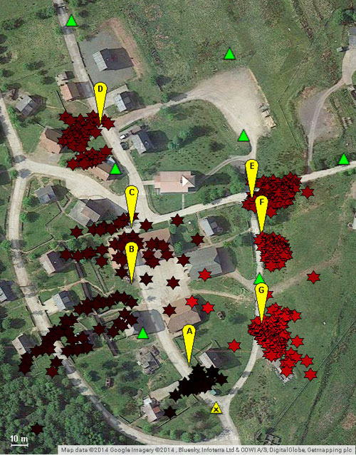
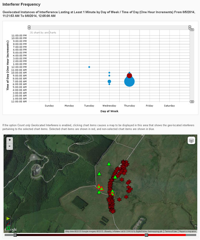
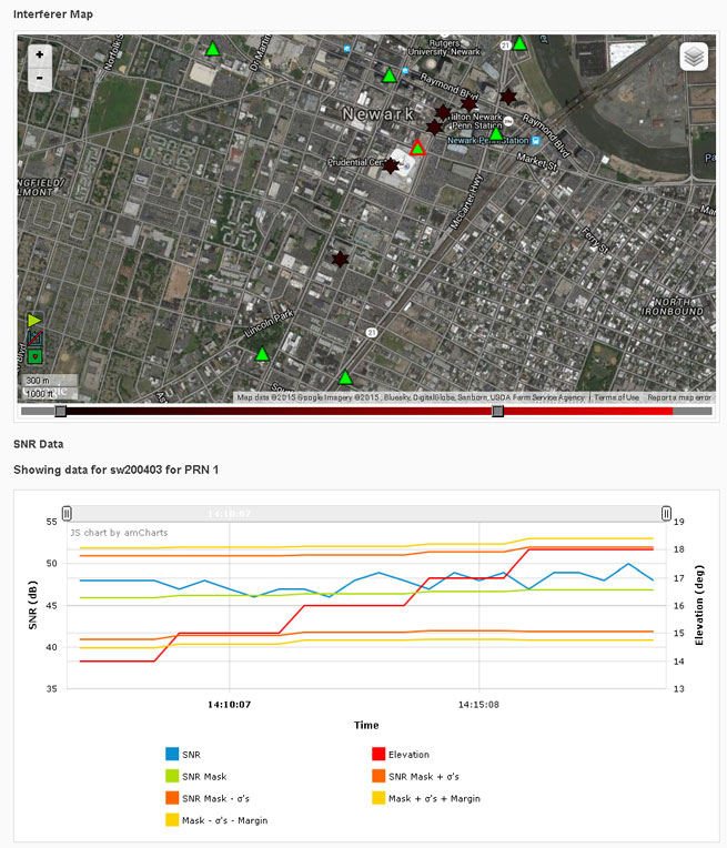
Signal Sentry 1000 is based on a server/client model. The user accesses Signal Sentry using a URL and secure log-in specific to the user’s system. The user’s particular home screen displays a map with each installed sensor displayed with an icon reflecting status. Interferers are displayed as red stars or as error ellipses.
The Signal Sentry web page lists all the interferers stored in the database with their start and end times. The user can manipulate the list by changing the minimum duration of the event to be displayed as well as if the interferer had been geolocated or not, or both. If an interference event was less than a minute long, it may not have a geolocation entry.
Geolocation Methodology. Geolocation of jammers is accomplished through proprietary algorithms running at the network server that utilize digitized, timestamped I and Q samples of received interference waveforms, GPS observables, and other parameters captured by each sensor. This data is processed in a Kalman-filter based location algorithm to determine an initial jammer position and track the position of the jammer throughout the jamming event. This improves performance with moving jammers (that is, vehicle-based) and enables continued jammer location with a limited sensor set (potentially due to signal blockage, erroneous data due to multipath, or out-of-range conditions). Upon detection of an interference event by any sensor, the server polls the entire sensor network for data and determines if the information is sufficient to perform geolocation.
The user receives near-real-time status of event detections and geo-location of the interferer (if possible). Sensor data polling, geolocation processing and GUI updates continue until the interference stops or the emitter goes out of sensor range. Sensor data from each event is stored for later replay and processing using Signal Sentry event analysis tools.
An interference event frequency chart (Figure 1) provides a tool for forensically evaluating the occurrence of interferers. It displays interference events as circles; the size of the circle represents the number of events that occurred at that day of the week and time. When dots are selected on the chart, a map below the chart shows the location of the interference events. More than one dot can be selected at a time. This allows a user to find correlations in time and space, to determine if events occur at specific locations at certain times of the day and/or days of the week.
FIGURE 1. Interference event frequency chart.
Selecting the interferer on the map and then the details button on the popup brings up the interferer details page (Figure 2). Users can sign up for interferer alerts to be sent to their email or phone by text.
FIGURE 2. Interferer details.
Testing
Signal Sentry 1000 was deployed and tested in GPS jamming trials at Sennybridge, United Kingdom, in August 2014. Testing included stationary jammers and mobile jammers moving at up to 50 mph, in open fields and built-up areas.
Sentry Arrayed. The sensors used in these trials were custom units designed and built to Harris specifications by Chronos Technology Ltd. Each consisted of an embedded GPS receiver, an interference signal receiver and a local processor with a network communications interface.
An array of eight sensors was geographically distributed around the test facility. Each sensor and a centralized Signal Sentry processing server were equipped with a mesh data networking capable radio for wireless data communications of commands, status and event data. In other Signal Sentry deployments, the server software is typically hosted on a cloud server, and sensors communicate with the server either via hard-wired internet connections or wirelessly through cellphone network-compatible data adapters.
Jammer Profile. Two jammers performed during the trials, a 150mW and a .5W jammer, used to disrupt the GPS L1 C/A code at 1575.42 MHz.
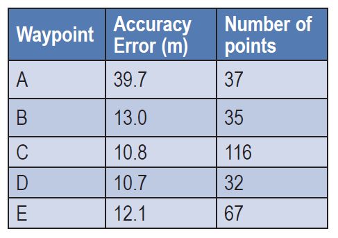
Open Field. Atest in an area with no obstructions included static jammers and dynamic jammers. Five waypoints along the road, in an area measuring 320 by 444 meters, were surveyed prior to the test using a handheld GPS receiver, to evaluate location accuracy.
Table 1 shows static test results. The accuracy error is the average delta between the Signal Sentry-reported jammer positions versus the actual surveyed jammer positions. The number of points column contains the number of measurements reported by Signal Sentry during the test scenario for each waypoint. The overall average accuracy error for the static jammer test was 17.25 meters.
TABLE 1. Open field static accuracy.
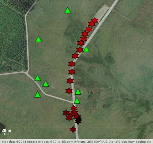
Open Field, Mobile Jammer. In these tests, the jammer was driven in a car on the road through the sensor field. The car was driven at 25 mph north to south, then 50 mph south to north (Figure 3). Cars in the north parking lot caused multipath errors when the jammer came in contact with that area.The overall average accuracy error for the dynamic tracking was 10 meters.
FIGURE 3. Jammer locations detected by Signal Sentry, when jammer was driven at 50 miles per hour, north to south. Green triangles denote sensor locations.
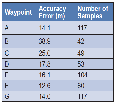
Obstructed Area Test. This test evaluated performance in an urban environment called a FIBUA (Fighting in Built-up Areas), using stationary and dynamic jammers. Seven waypoints in an area 176m x 253m were surveyed for the purpose of evaluating location accuracy. Table 2 shows the results with the 150mW jammer held stationary at the waypoints. Figure 4 provides a graphical view of the jammer position in relation to the waypoints. The overall average accuracy error is 21.40 meters.
TABLE 2. Urban static accuracy.
Obstructed Area, Mobile Jammer. In these tests, the jammer was driven in a car at approximately 20 mph on the road through the sensor field, using a .5W jammer. The overall average accuracy error for this dynamic tracking was 50 meters.
FIGURE 4. Urban area test; jammer locations in yellow, locations delivered by Signal Sentry in red, sensor locations in green.
All figures provided by Jeffrey Coffed and Joseph Rolli.
Singapore and China are jointly opening a center to develop applications for the BeiDou GNSS, according to a report in Space News. The nations also have signed a commercial agreement to create anti-jamming systems to protect BeiDou signals.
At a briefing during the CommunicAsia show held in Singapore May 31-June 2, SpaceTime Technology Pte Ltd. and ST Electronics (Satcom & Sensor Systems) Pte Ltd. signed a memorandum of understanding to “develop in Singapore an interference-resistant Beidou satellite positioning system,” SpaceNews report.
The companies said the goal is to protect BeiDou signals from unintentional jamming in urban environments, where wireless devices occasionally overstep their radio-frequency boundaries.
At the European Navigation Conference held in Bordeaux, France, April 7–10, a keynote session and ensuing panel discussion addressed the issue of “GNSS Resilience for Terrestrial and Naval Applications.” During the discussion, two questions from the floor drew these responses from panelist Jan Wendel of Airbus Defence & Space GmbH, a leading European aerospace company.
Do you believe that receiver manufacturers will be able to deliver resilient receivers in the future?
JW: In order to achieve resilience, regulatory measures can only provide a mid- to long-term solution. Therefore, resilience needs to be addressed at the receiver level as well.
Considering spoofing, I am not aware of any confirmed spoofing incident. Iran has been claiming to have spoofed a CIA drone, which became for me at least theoretically feasible when I heard the rumor that this drone was equipped with a GPS C/A code receiver. Also, there has been a wrongly configured repeater at the Hannover airport. Nevertheless, spoofing to me does not seem to be a current threat.
However, jamming is clearly a reality nowadays. In my opinion, we should first decide which level of resilience we actually want to achieve for which type of user receiver. If the simple receivers like in smartphones become more and more robust against jamming, the simple jammers available on the Internet will react with an increasing jamming power. This will leave less margin for the receivers used in more critical applications, which we really would like to see functioning permanently.
Therefore, resilience for low-end receivers might not be a good idea; maybe it would be better to see them fail in some scenarios.
Another aspect in the discussion we have had so far is the spreading-code encryption for authentication purposes. Actually, I see spreading-code encryption more as a means to restrict the access of a GNSS signal to authorized users and as an anti-spoofing measure, but not primarily as a means for authentication. Here, we must be aware that the access is not necessarily as restricted as we would like to think.
With directive antennas, blind demodulation techniques and a communication link, it is possible with a slight delay to achieve a position, velocity and time solution at a rover, without being an authorized user of the respective service.
We must understand resilience also in a more global sense, that such a possibility must not be detrimental to the applications assuming a restricted access to specific GNSS services.
Do standards help?
JW: In general, standards are a good thing, as they help in the construction of complex systems by assuring interface compatibility and also minimum performances. However, care needs to be taken when the standards are defined. For example, in the NMEA 0183 protocol, essential information is missing that is required for integration of a GNSS receiver with an inertial navigation system, for example, vertical velocity, full variance-covariance matrices of the receiver’s position and velocity, or raw data like pseudorange, delta ranges and ephemeris to name a few. Clearly, the NMEA protocol was not designed for GNSS/INS integration, and for its intended use the NMEA protocol fits perfectly.
However, for many applications, it is not usable. Being a de-facto standard offered by most receivers, I think it would be beneficial if this protocol would follow more a general-purpose spirit, like most of the proprietary protocols of the different receiver manufacturers do. So with the NMEA protocol lacking relevant information, we are in a situation where for many applications either the receiver manufacturers’ proprietary protocols have to be used — given these protocols offer the required information — or the receiver cannot be used at all. For me, this is an example where a standard is not of great help, also because the process of developing such a standard towards an extended scope takes considerable time, if possible at all.
Jan Wendel is a system engineer at Airbus DS GmbH in Munich, Germany, where he is involved in activities related to satellite navigation, including tracking, integrity and sensor integration algorithms. He received the Dr.-Ing. degree from the University of Karlsruhe, where he is also a private lecturer.
A fully autonomous, unmanned aerial vehicle (UAV)-based system for locating GPS jammers, currently under development, seeks to localize a jammer to within 30 meters in less than 15 minutes in an area comparable to that of an airport. Ultimately, the design team targets the ability to locate multiple, simultaneous jammers, and navigate in intermittent GPS and GPS-denied environments using a combination of GPS and alternate navigation aids. The system should be inexpensive and built from commercially available or open-source parts and software.
By James Spicer, Adrien Perkins, Louis Dressel, Mark James, Yu-Hsuan Chen, Sherman Lo , David S. De Lorenzo and Per Enge, Stanford University
The aviation community worries about GPS jamming. Recently, it struggled to find so-called personal privacy devices on Newark’s Liberty International Airport and traveling the nearby New Jersey Turnpike.
A number of unintentional jamming incidents took a long time to resolve. The disruption from an intentional, malicious jamming attack could be far worse. Airport authorities should be prepared to locate and shut down a coordinated attack by numerous jammers capable of disrupting the GPS service over an entire airport.
The closure of a major airport for the many hours or days it would take to locate even a couple of backpack-sized transmitters would be not only be highly disruptive in flights delayed or diverted, it would negatively impact the confidence of the flying public.
Any system in place to mitigate this threat must be inexpensive enough to be deployed at least at the nation’s major commercial airports, autonomous enough to be operable with limited training and certification, and rapid and accurate enough that a jammer can be routinely apprehended by ground-based law enforcement. It must be able to navigate successfully in GPS-denied environments using alternative position, navigation and timing (APNT), and have the range and capacity to search an airport-sized area as well as the approach corridor leading to runway touchdown.
This article describes such a system and device presently in research and development: the Jammer Acquisition with GPS Exploration & Reconnaissance (JAGER).
Vehicle Design and Operation
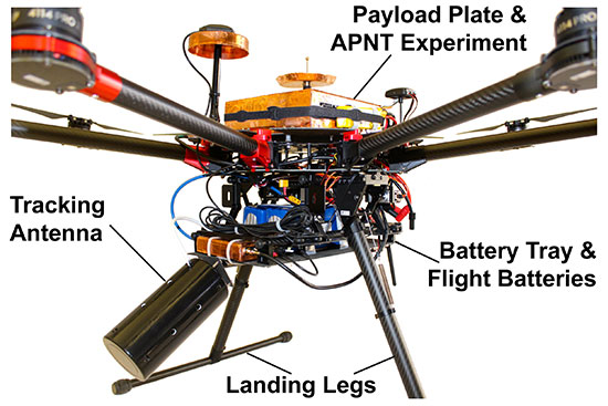
The JAGER UAV is a based on a commercially available, multi-rotor airframe modified to suit the mission specifications. The 1.2-meter diameter octocopter has a maximum takeoff weight of 11 kilograms (24.2 pounds), a top speed of 20 meters/second (m/s, 45 mph), and can fly unloaded for up to 30 minutes.
We have replaced the battery tray with our own carbon fiber design that allows us to carry 16 Ah of lithium polymer batteries for a maximum power draw of 4 kW. This extra capacity means that even with a 5-kilo experimental payload, the present craft can remain aloft for up to 15 minutes without recharging.
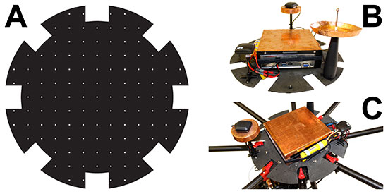
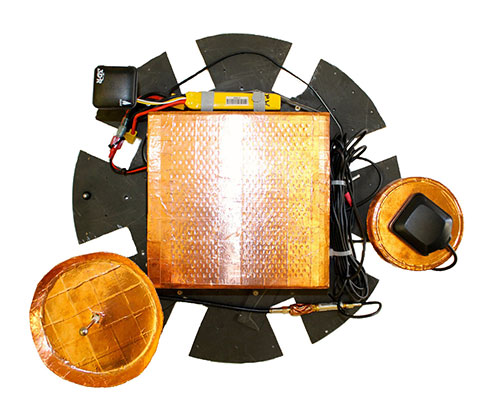
The payload plates are also custom-made from carbon fiber, and it is to these that the UAV’s experimental payloads are mounted (see FIGURES 1 and 2). One payload plate is flown at a time, and is secured on top of the airframe with a quick-release mechanism. This modularity allows for individual experiments to be mounted to their own payload plate and ground-tested before being secured to the UAV. Different experiments can be switched out rapidly for efficient use of battery capacity and flight time.
Figure 1. (A) Diagram of the payload plate showing regularly spaced mounting holes. (B) Plate with APNT experiment mounted. (C) Payload plate / experiment assembly secured atop JAGER UAV.Figure 2. Image of the vehicle showing the battery tray slung beneath the central body, the APNT experiment and payload plate secured on top, and the jammer-hunting antenna mounted at the front.
The plate itself also offers flexibility for component mounting. Regularly spaced, threaded holes across the plate mean components’ positions can be easily changed to find an optimal configuration. This can be particularly useful for minimizing interference between computers and noise-sensitive components such as antennas and magnetometers.
Software. We modified existing, open-source autopilot software to fly the mission. The craft is fully capable of completing a mission autonomously, but also can be taken over by a human pilot if necessary. A ground station also can be used to send commands to the octocopter, but is primarily used to monitor UAV location, battery life, and jammer belief state.
The autopilot software also has been adapted to communicate with various vehicle payloads. Experiments using APNT equipment, for example, pass their data to the autopilot, which will combine these signals with its own GPS data for accurate navigation in areas where the GPS signal might be intermittent or unreliable. In return, the autopilot can be used to pass data to experiments reliant on altitude, attitude, atmospheric pressure or location information.
The ground station monitors instruments’ data and status in real time. This not only allows for control of airborne experiments, but also straightforward ground testing. Synthetic autopilot data can be fed to an experiment to ensure that all systems are performing correctly before they are mounted on the vehicle for flight tests.
APNT Overview
Key to navigating in a GPS-denied environment is the use of signals from APNT networks for location determination. The proposed system should be able to navigate using any or all available APNT signals, and should weight each one according to its strength and reliability in order to formulate the most accurate estimate of both its own and the jammer’s position.
Here we describe the use of the universal access transceiver (UAT) and distance measuring equipment (DME) network for our APNT signals. The UAT signal has been implemented by the Federal Aviation Administration (FAA) in the United States as part of automatic dependent surveillance–broadcast (ADS-B), and is transmitted through a network of terrestrial ground stations.
The ADS-B network was only completed across the contiguous United States in 2014, so it is new compared to established cellphone networks. It is more comprehensive than many other terrestrial systems, so that coverage of most airports is guaranteed. While GPS reception requires an unobstructed view of the sky, UAT reception requires a direct line of sight to a transmitting tower. However, the flatness of terrain surrounding most airports as well as the UAV’s airborne vantage point ensures that UAT signals will probably be visible throughout most jammer-seeking missions.
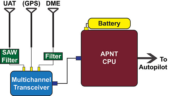
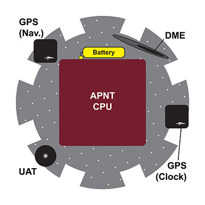
The APNT equipment used for navigation by the JAGER UAV consists of UAT (978 MHz), DME (982 to 1213 MHz), and GPS (1575.4 MHz) antennas, a multichannel transceiver to combine the two signals, and a computer for data processing (see FIGURE 3). A dedicated lithium-ion battery powers the entire APNT payload. The current system does incorporate GPS to estimate the time offset, but future iterations of the system will derive time from sources other than GNSS so that true GPS-denied navigation is possible.
Figure 3. Schematic of the APNT configuration on board the JAGER UAV. Resulting location information is passed to the autopilot for navigation.
The UAT antenna receives multiple signals from visible ADS-B ground station transmitters. The transceiver combines these with a GPS timestamp, and the data is passed to the APNT computer for analysis. Based on knowledge of the absolute locations of the ADS-B antennas, the range of the vehicle from each antenna can be calculated, which in turn can be used to trilaterate the vehicle’s absolute position. This position is then passed to the autopilot for the UAV’s navigation, while the status of the equipment and signal strength are passed down to the ground for monitoring in real-time.
The necessity of using GPS signals as an accurate timing system is a current limitation, as navigation in GPS-denied conditions is clearly not possible while we are using GPS as a clock. As mentioned eariler, future designs will derive time from non-GNSS sources, such as chip-scale atomic clocks or the terrestrial ranging signals.
Carrying an onboard computer allows for real-time processing of the terrestrial alternative navigation signals. However, there are a few limitations to the use of these signals. First, the vertical position is difficult to calculate due to the geometry of terrestrial signals as well as the sparsity of visible station at low elevation. This is solved by using a baro-altimeter. Second, DME signals do not provide a pseudoranging function. Current work sponsored by the FAA is developing a DME pseudoranging capability. As the technology matures, we will improve the hardware and algorithm that can be integrated into future JAGER designs, resulting in lower weight and power overhead for the APNT payload.
Tracking Overview
GPS jammers do little more than emit signals in the GPS frequency range. Because the signals from GPS satellites are so weak by the time they reach the Earth, ground-based jammers do not have to be especially powerful to overwhelm GPS in their immediate vicinity. A jammer is no more than a ground-based radio-frequency source radiating within the GPS spectrum.
The JAGER system will autonomously locate the nearest beacon emitting electromagnetic signals at the target frequency: the GPS frequency in this scenario. Testing such a system is difficult due to the illegality of jamming the GPS signal within the United States. We instead test the system using a powerful Wi-Fi beacon as a proxy for the overpowering jammer. Excepting the target frequency, the procedure to locate the jammer is identical to the GPS case.
To receive the jamming signal, the front of the craft carries an antenna optimized to receive signals of the target wavelength; the current antenna has a 60° cone of maximum sensitivity. It is angled downward 30° from the horizontal, so that the craft can receive all signals from the horizon to 30° from vertical. This gives the UAV visibility over most of the space in front and underneath it. Like the other payload equipment on the vehicle, the antenna is secured with a fast-release mechanism so that it can be easily swapped out if necessary. For Wi-Fi tracking, we use a Yagi antenna with 60° beamwidth and 9 dBi gain. In upcoming trials, we will test different antenna configurations (such as dual antennas, small antenna arrays, and directional antennas augmented with omni-directional antennas) to determine benefits of these different layouts.
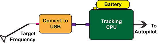
Signals from the antenna are passed into a module that converts the Wi-Fi data to serial, then from serial to USB. A single-board Linux computer with a quad-core processor then analyzes the signal data (see FIGURE 4). The hardware used to locate the jammer weighs 160 grams, so has negligible impact on the vehicle’s flight time or range.
Figure 4. Schematic of the tracking system on board the JAGER UAV. The resulting believed location of the target is passed to the autopilot.
To find the jammer’s location, the UAV performs a controlled yaw spin while recording the strength of the jamming signal. On the basis of the signal landscape surrounding the vehicle, the computer estimates the jammer’s location and sends a message to the autopilot instructing the craft to fly in that direction (or, more accurately, in a direction that optimally improves the ability of JAGER to find the jammer quickly). In return, the autopilot updates the tracking computer and ground station as to the vehicle’s position.
After moving a certain distance towards the jammer’s believed location, the craft repeats the spinning maneuver and starts the process again. Although rotating only the antenna might increase the speed of the operation, the energy required to carry the necessary antenna-rotation mechanisms for the duration of a flight is more than that needed to spin the entire craft.
The tracking algorithm is not as straightforward as gradient ascent or homing, and the vehicle will not always fly in the direction of greatest signal strength. The operational area is uneven, and may include buildings, towers, or airplanes, resulting in a complicated RF environment. Signals are scattered, diffracted and reflected, meaning that an algorithm that simply follows the strongest signal will not always converge on the actual jammer location.
To decide the optimal path from the vehicle’s present location to the jammer’s believed position, the tracking algorithm makes use of partially observable Markov decision processes (POMDPs). POMDPs model decision processes where the underlying state of the system (that is, the location of the jammer) is never completely known, and maintain a probability distribution over the set of all possible states.
The entire deployment area (an airport and its environs, for example) is split up into a square grid. For every possible combination of jammer and vehicle grid square locations, the signal strength and direction that would result is calculated offline prior to deployment and stored in a database on the tracking computer.
During the mission, the UAV records its own position and the sensed jamming signal’s strength and direction. The jammer location that would correspond to this result is retrieved from the database, as well as a measure of the strength of this belief state.
Once the craft has a belief as to the location of the jammer, it moves to a new location in the jammer’s believed direction before taking another measurement of signal strength. The new location and new measurement are combined, and the updated corresponding jammer location is retrieved from the database. This process is repeated until the vehicle believes itself to be right above the jammer, at which point a photograph is taken, the ground station is notified, and the hunting mission is complete.
Having found the jammer, the system can be programmed to execute a wide range of operations. These include reporting coordinates and a live image of the believed jammer location back to the ground station, hovering above and tracking the jammer if it begins to move, landing at the jammer site, or returning to base.
We calculate and store the POMDP decisions in advance of the flight. This strategy has some advantages. First, it allows for almost instantaneous decision-making. This is because the algorithm’s decisions are based solely on the vehicle’s current location and sensory observations and not on any previous states (a defining characteristic of a Markov decision process). The craft needs only to observe its current state in order to look up its next move in the database. This enables rapid tracking in flight.
A second advantage is that safety checks can be pre-programmed into the database in advance of deployment. While JAGER is programmed to move towards the grid square believed to contain the jammer, it can also be programmed to avoid or take special precautions when moving towards or in the vicinity of certain squares in the grid (also called geo-fencing). In an airport situation, for example, the vehicle would avoid moving into the square containing a control tower or ground-based antenna, or would fly at a minimum altitude over buildings and taxiways to avoid collisions.
Finally, the integration between the autopilot and the tracking software can provide other important safeguards: in the proof-of-concept system, any navigation decision taken by the software can be relayed to the ground for human verification before the UAV begins to move. This supervised mode of operation lends itself to a seamless migration path to fully autonomous operation (always overseen by a human operator).
However, one disadvantage of calculating and storing decisions in advance is the storage space needed on the vehicle. Because the result of every possible combination of vehicle and jammer locations within the grid is calculated, the size of the database grows quickly with increasing numbers of possible positions (and states). The larger the grid or the greater the required accuracy, the more space is needed to store the database. With current algorithms, the database needed to locate a jammer to within 30 meters in an area the size of an airport requires 15 gigabytes of storage space, resulting in longer lookup times during flight.
We are considering several strategies to mitigate this disadvantage, including better compression, more effective search algorithms, and uploading from a ground server only the parts of the database that correspond to the vehicle’s current operational area. Another strategy is to use an adaptive mesh that changes in resolution depending on the jammer’s belief state: at low certainty the database resolution is low, but increases in the appropriate area as the jammer’s location becomes more certain.
Another disadvantage of pre-solving the decision-making process is that the system must be reconfigured for every site in which it is deployed. The specifications of the tracking algorithm will change depending on the requirements of the operating area. The grid size, shape and absolute location must change to suit the area being protected. The resolution of the grid depends on the required accuracy of the tracking system, and restricted or prohibited locations must suit the terrain, buildings and geological features of the deployment space. For example, a lead JAGER vehicle could be adapted and tested to suit a particular airport, and then the bespoke algorithm and database uploaded to backup vehicles in that airport’s fleet.
APNT Performance
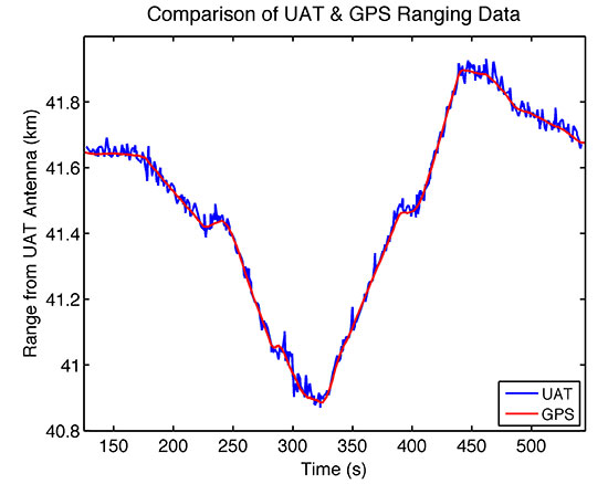
During the Joint Interagency Field Experimentation (JIFX) event at Camp Roberts, California, in November 2014, we tested the APNT system by deploying the vehicle with GPS, UAT and DME antennas simultaneously recording data. GPS receivers on the ground were used to collect reference measurements to estimate the time of transmission of the signals from the APNT sites. All signals were recorded at an altitude of 275 meters above ground level (600 meters above sea level), at four different points roughly 800 meters apart, and the data analyzed for comparison. As expected, the UAT broadcast was noisier than the GPS signal. However, it was possible to calculate a range from the UAT data that was accurate to within 16.6 meters of the GPS reference position, well within the 30 meters error bound specified in the project specification (see FIGURE 5).
Figure 5. UAT range deviates from GPS derived range-estimate by an average of only 16.6 meters throughout the duration of the test flight.
While UAV navigation using APNT was done offline in post-processing for these tests, with planned algorithm improvements and hardware acceleration the UAT signal can be used to get real-time position information nearly as accurate as that from GPS. Thus the JAGER UAV can be navigated with comparable reliability in both GPS and GPS-denied environments.
Terrestrial APNT signals will be received at a wide range of power levels. This effect is not observed with the GPS network, as the different satellite signals are broadcast from such a great distance that any differences in received signal strength are relatively small by the time they reach Earth. For terrestrial networks, signals from transmitters close to the receiver can be many times stronger than those further away, which can result in two issues: 1) interference where one signal overwhelms another, and 2) inability to process a signal if the receiver does not have adequate dynamic range to capture strong and weak signals clearly.
This problem was observed in our tests, as we were receiving two signals: one 13.7 kilometers (DME) and the other 43.5 kilometers (ADS-B UAT) from our test site. Calculating accurate ranging estimates from the two required determining a gain setting that had dynamic range adequate for receiving both signals clearly.
Vehicle Performance
During experimental testing, the vehicle itself also underwent rigorous assessment of its performance under different conditions. Due to the delicate and often expensive nature of the payloads and experiments made possible by the JAGER platform, it is essential that the vehicle perform as expected, and that there are multiple procedures in place to protect the payloads in case of vehicle failure.
Because the open-source autopilot had never been used with such a large vehicle, we first ground-tested the craft’s flight control and stability. The vehicle was tethered and constrained to move in only one axis, and ropes were used to control its roll. While altering autopilot variables controlling roll and pitch feedback loops, we measured the vehicle’s response to impulsive disturbances and the time taken for it to right itself when upset. In this way we could tune the control gains and verify that the vehicle would be exceptionally stable during flight in even the most challenging atmospheric conditions. While we preferred to fly in the early morning hours to exploit clear air and lower winds, we did perform tests with momentary gusts of up to 7 m/s during envelope expansion flights.
We tested the vehicle with two accelerometers on board to measure how the rotors’ vibrations affected the rest of the craft. One accelerometer was attached to the airframe itself, while the other was secured to the payload plate. A comparison of the acceleration data recorded by the two instruments revealed that the payload plate experienced significantly less vibration than the airframe during flight, and both measurements remained well within the tolerances advised by the airframe manufacturer.
Two crucial flight modes also were tested before payloads were flown on the vehicle. Both altitude-control mode and position-control mode were tested to ensure that they could precisely constrain respectively the vehicle’s altitude and absolute position in a range of atmospheric conditions. Results showed that in altitude control mode, the vehicle’s z-coordinate was held constant to within ± 0.5 meters. In position control mode, its x- and y-coordinates remained within ± 1.0 meters (or a single vehicle length).
The success of the JAGER tracking mission also depends on accurate position measurements from the UAV. Operators must be confident in the vehicle’s position, so that ground forces can easily apprehend the located jammer, and also so that there is confidence in the success of safety protocols including geo-fencing, no-fly zones and minimum flight altitudes.
In addition to the geo-fencing and flight precautions taken by the tracking algorithm, the JAGER UAV has several other safety procedures executed automatically by the autopilot. A non-catastrophic error in the flight systems or payload is transmitted to the ground station for human troubleshooting, and commands can be sent to the vehicle as to how to proceed.
Finally, should we continue operations and allow its batteries to get sufficiently low, the vehicle will automatically return to launch site for landing and battery replacement. A catastrophic failure such as the loss of a motor will result in an immediate controlled landing. The craft can also be commanded from the ground station to land or return to launch, and can be taken over by a human pilot at any time.
Other tests verified that the vehicle has the range and endurance to be successful when deployed in an airport setting. When fully loaded with APNT and tracking payloads, the UAV exhibited a top speed of 10 m/s, enough to cover the length of an A380-capable runway in less than 5 minutes. A 20-minute flight endurance means that even including hovering during jamming signal observations by the tracking antenna, the JAGER system can hunt easily and effectively throughout an airport-sized area. Furthermore, we continue to explore techniques to improve dash capability, including reducing the weight of the APNT payload, and we anticipate describing results of these efforts in future reports.
Electromagnetic Interference
Because of the payload tray’s small area (0.5 m2), electromagnetic interference (EMI) between APNT components was a significant issue during testing. The GPS and UAT receivers are extremely sensitive to interference from other sources emitting in the frequency ranges to which they are tuned. The APNT computer, by contrast, is composed of various processors, clocks, drives and power boards that emit powerful electromagnetic noise at a wide range of frequencies as a byproduct of their normal operation.
The size and mass of the APNT computer board meant that it had to be mounted in the center of the payload tray to avoid unbalancing the UAV. That left a maximum 7 centimeters of space around the computer on which to mount the two antennas (see FIGURE 6). With no shielding, the EMI from the computer proved powerful enough to completely overwhelm the GPS, UAT and DME network signals, making navigation and position estimation using any network impossible.
Figure 6. Diagram showing the APNT experimental payload, and the proximity of the EMI-radiating CPU to numerous antennas.
The EMI problem was solved in three ways. Masts were used to raise the receiving antennas to a height of 19 centimeters above the payload tray, the maximum height at which a mast collapse wouldn’t cause catastrophic rotor and vehicle failure.
The antennas also were moved around the edge of the payload tray so as to be furthest from the system components radiating at their particular frequency. Two devices that proved particularly problematic were the solid-state hard drive in the CPU and the telemetry radio antenna, which radiated EMI that interfered with the GPS and UAT frequencies respectively. This was solved by moving the telemetry antenna to the underside of the craft, and the GPS antenna to the far side of the payload plate from the hard drive. The flexible design of the payload plate described earlier ensured that the relocation and testing of components was a straightforward process.
Shielding, however, proved to be the most important factor in eliminating EMI. Custom-made copper shields were added to the two masts to shield the antennas from the computer below them while still allowing an unobstructed view of the sky (see PHOTO). We tested numerous shielding iterations, including wire meshes and aluminum and lead foils; however; all were ineffective due to the strength and wide range of EMI wavelengths emitted. Finally, the computer itself was covered in a 2-millimeter layer of copper and 1-millimeter steel sheet. This combination struck the best balance between effectiveness and weight: aluminum was light but proved ineffective at shielding, while lead was very effective at EMI shielding but was too heavy for the UAV to carry.
The APNT payload prior to installation of the DME antenna. The copper shielding on the CPU and antennas can be clearly seen.
Conclusions
The development of the JAGER system contributes to U.S. preparation for a GPS jamming attack on civil aviation. While the first iteration described here is a significant improvement on previous jammer-hunting systems, future iterations of the JAGER UAV will be able to successfully navigate in a GPS-denied environment using alternative navigation signals including UAT and DME, and broadcast an accurate estimate of their position down to the ground.
The use of an octocopter flight system gives speed, maneuverability and sensory perception that far exceed any ground-based tracking effort. A fully loaded top speed of 10 m/s and almost instantaneous direction changes allow for efficient hunting over an airport-sized area and the location of a GPS jammer to within 30 meters, within a 20-minute flight endurance.
As the JAGER system can be entirely assembled from commercially available or open-source components and operates entirely autonomously, the system provides a low-cost, readily obtainable solution to the problem of GPS jamming. This means that it can be deployed quickly and is operable without extensive prior training.
The integration of autopilot, APNT navigation and tracking systems also allows for comprehensive monitoring and control of the UAV from the ground. Telemetry and data links to the ground station provide real-time updates as to the craft’s position, the jammer’s believed location and the status of all systems and instruments running on the vehicle. Safety protocols implemented in the software ensure that there is no risk of collision with site buildings, vehicles or personnel.
JAGER’s modular design gives operators extensive flexibility in situations that are capable of being successfully resolved by the system. The switching of equipment and software to allow the UAV to use GPS navigation to hunt a UAT or DME jammer, for example, could be effected in a matter of seconds.
The JAGER system also provides a reliable test platform for any experiment that requires airborne operation. The exceptional stability of the airframe combined with extended flight time, high top speeds and pinpoint positioning lends the system to a wide variety of applications beyond jammer tracking, including network monitoring, atmospheric experiments and biological research.
Manufacturers
The JAGER UAV airframe is a S1000 octocopter by DJI Innovations, Shenzhen, China; the flight batteries are a 8000 mAh model by Hextronik, Dongguan, China; the autopilot hardware and GPS antenna is a Pixhawk by 3D Robotics, Inc., San Diego, California; the autopilot software is based on PX4 by Pixhawk.org. The JAGER navigation GPS is made by u-blox, and the receiver for the APNT clock is made by Trimble. The UAT hardware includes an ASR-2300 multichannel transceiver by Loctronix Corporation, Woodinville, Washington; the tracking hardware comprises a 2.4 GHz Yagi antenna from L-com, North Andover, Massachusetts; an RN-XV Wi-Fi module by Roving Networks, Chandler, Arizona; and an Odroid-U3 computer by Hardkernel Co., Gyeonggi, South Korea.
James Spicer is pursuing concurrent bachelor’s and master’s degrees in aeronautics and astronautics at Stanford University.
Adrien Perkins is a Ph.D. candidate in aeronautics and astronautics at the Stanford University GPS Laboratory. He received his undergraduate degree in mechanical aerospace engineering at Rutgers University.
Louis Dressel is a graduate student at Stanford University. He received his undergraduate degree in aerospace engineering from Georgia Tech, with a minor in computer science.
Mark James is a master’s student in aeronautics and astronautics at Stanford University.
Yu-Hsuan Chen is a research associate at the Stanford GPS Laboratory. He received his Ph.D. in electrical engineering from National Cheng Kung University, Taiwan.
Sherman Lo is a senior research engineer at the Stanford GPS Laboratory.
David S. De Lorenzo is a principal research engineer at Polaris Wireless and a consulting research associate to the Stanford GPS Laboratory.
Per Enge is a professor of aeronautics and astronautics at Stanford University, where he is the Vance D. and Arlene C. Coffman Professor in the School of Engineering. He directs the Stanford GPS Laboratory.
KVH Industries Inc. has received a $1.5 million contract for the delivery of tactical navigation systems for use by an international military customer in an armored vehicle application. A variant of KVH’s TACNAV TLS and TACNAV Light, the system is designed to help military vehicle crews maintain 100% situational awareness. The hardware shipments for this order are expected to be made in 2015. Program management and engineering services will be provided as part of this order.
“KVH’s TACNAV navigation solution is an important tool for U.S. and allied warfighters, providing precision navigation as well as coordination of vehicles in critical situations,” said Dan Conway, executive vice president of KVH’s guidance and stabilization group. “The system serves as a crucial resource for navigation and battle management, keeping soldiers safe and out of harm’s way wherever they travel. This new order reaffirms the value of KVH’s TACNAV products for international militaries, and adds to our backlog for the year.”
The TACNAV TLS by KVH Industries.
All of KVH’s TACNAV military vehicle navigation systems provide unjammable precision navigation, heading, and pointing data for vehicle drivers, crews and commanders, KVH Industries said. TACNAV can also serve as a heading and position source for situational awareness.
The TACNAV system ordered combines characteristics of TACNAV TLS and TACNAV Light, and features a compact design, continuous heading and pointing data output, and a flexible architecture that allows it to function as either a standalone navigation module or as the heart of an expanded, multifunctional TACNAV system. The system is designed to integrate with battle management systems and is a vital component for effective battlefield management, KVH Industries said.
TACNAV systems are in use by the U.S. Army and Marine Corps, as well as many allied customers including Canada, Sweden, Great Britain, France, Germany, Spain, Egypt, Botswana, Australia, New Zealand, Saudi Arabia, Taiwan, Romania, Poland, Turkey, Malaysia, Switzerland, South Korea, Singapore, Brazil and Italy.