NASA’s concept for a possible UTM system would safely manage diverse UAS operations in the airspace above buildings and below crewed aircraft operations in suburban and urban areas. (Image: NASA)
Silent Falcon UAS Technologies participated in the NASA UTM (unmanned traffic management) project headed up by the NASA Ames Research Center, held this month in Reno, Nevada.
NASA and the Federal Aviation Administration (FAA) are working together to identify ways to safely enable large-scale UAS operations in the low-altitude airspace. The growing number of UAS and commercial UAS applications has led to this critical project.
The UTM flight tests took place the week of Oct. 17. Silent Falcon, along with 11 other partners in the UTM program, flew their aircraft in typical UAS scenarios.
The tests focused on the ability to alert and inform airspace users of potential dangers and conflicting situations that go BVLOS (beyond visual line of sight) as well as within VLOS (visual line of sight). Safety is of utmost importance and visual observers will be put in place to ensure aircraft stay on their designated paths and won’t interfere with other aircraft in the area.
Silent Falcon
Silent Falcon is a solar electric, carbon fiber, modular small Unmanned Aircraft System (sUAS) designed for numerous commercial, public safety, military and security applications.
Silent Falcon’s solar electric propulsion systems gives it the unique ability to stay in the air for extended periods of time — five or more hours depending on environmental conditions. It’s also what gives the Silent Falcon its ability to be virtually silent. Once the Silent Falcon reaches 100 meters, it’s effectively undetectable.
The composite structure of the Silent Falcon provides exceptional durability while flying in all types of conditions, as well as for launch and recovery. It’s also very lightweight for ease of transport and in-air maneuverability.
The Silent Falcon UAS prepared for launch. (Photo: Silent Falcon)
Using a highly sophisticated mesh network, wave relay communication system, the airborne network nodes provide seamless dissemination of voice, video and data. With an internet connection on the ground, users can provide secure and encrypted voice, video and data to anyone, anywhere in the world on a private Silent Falcon communication network.
The large, open payload bay of the Silent Falcon has been designed with an open interface and open architecture to accommodate a wide range of sensors, cameras and payloads. This allows the Silent Falcon to perform a large variety of extended range and endurance missions.
“We are extremely fortunate to be a part of this very important project – both in the actual flight operations, as well as the development of the UTM software,” said John Brown, Silent Falcon UAS Technologies president and CEO. “This project is extremely important to the UAS industry and is of particular interest to us as we manufacture a long-range, long-endurance fixed-wing UAS that was designed for BVLOS applications. We are grateful to NASA for including us and we look forward to further participation as the project continues to move forward.”
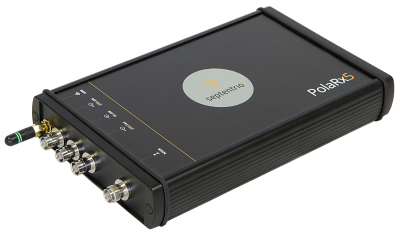
Septentrio has received a contract to supply 35 high-precision GNSS receivers to the Jet Propulsion Laboratory (JPL) for use in the NASA Global GNSS network (GGN).
The NASA GGN is one of the world’s largest global GNSS tracking networks with nearly a hundred reference receivers deployed worldwide and is a participant in the International GNSS Service (IGS). The GGN is also the core tracking network of JPL’s Global Differential GPS (GDGPS) System, a highly available and reliable service providing mission-critical position, navigation and timing data, as well as environmental monitoring for industry and government operations.
The Septentrio PolaRx5 GNSS receiver.
Under the contract, Septentrio will supply 35 of its new-generation PolaRx5 GNSS receivers, including 25 reference stations and 10 timing instruments. Deliveries began in August and will be completed in September.
The PolaRx5 incorporates Septentrio’s most advanced multi-frequency GNSS engine, which tracks all major satellite signals including GPS, GLONASS, Galileo and BeiDou, as well as the regional QZSS and IRNSS satellite systems. It provides measurement quality and interference mitigation, and operates on less than two Watts when receiving GPS and GLONASS satellite signals.
“This major contract with JPL — a widely recognized industry leader in GPS and GNSS technology — is an important validation of Septentrio’s position as the number one preferred supplier of highly accurate GNSS receivers for scientific applications, and recognition of the superior performance of our next-generation GNSS receivers,” said Neil Vancans, vice president of Septentrio Americas.
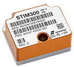
Sensonor AS is partnering with NASA to supply current and future low- and near-Earth orbit space missions with inertial and gyroscope modules.
The Norway-based company first began supplying its standard inertial measurement unit (IMU) and gyroscope modules for low Earth orbit (LEO) space applications in 2012, beginning with the launch of the NASA-sponsored AeroCube-4 satellite. Sensonor’s STIM300 and STIM210 inertial products are now a standard part in many spacecraft similar to the AeroCube-4.
Current NASA projects using STIM inertial systems include the Raven technology demonstration and Near Earth Asteroid (NEA) Scout.
Raven, which launches to the International Space Station in September, will test key elements of an autonomous relative navigation system. Its technologies may one day help future robotic spacecraft autonomously and seamlessly rendezvous with other objects in motion, such as a satellite in need of fuel or a tumbling asteroid.
The concept image above shows the NEA Scout CubeSat with its solar sail deployed as it characterizes a near-Earth asteroid. (NASA)
The NEA Scout is a robotic reconnaissance mission that will be deployed to fly by and return data from an asteroid representative of NEAs.
NASA, in conjunction with the Aerospace Corp., spearheaded the use of STIM products in space, and many other commercial launch and satellite companies have since followed NASA’s lead. In fact, more than 30 companies around the world use Sensonor inertial products in various space applications, with several satellites successfully flying with STIM gyroscope modules for over three years.
The STIM gyroscope modules are often used in combination with GPS or a Star Tracker and Kalman Filter to orient and stabilize the satellite, as well as to provide feedback on satellite motion induced by its reaction wheels. In some applications, the gyroscopes are used to stabilize satellite- to-satellite communications.
Being a supplier illustrates the trust NASA and others place in Sensonor, further solidifying the company’s role in this market. “We look forward to continuing to serve the international space community with our inertial offerings as standard commercial off-the-shelf (COTS) products. By serving the space market on equal terms with our other customers, we can help to reduce the cost of manufacturing and launching space payloads,” said Hans-Richard Petersen, Sensonor’s vice president of sales and marketing. “Our STIM products are the lowest size, weight, and power for their performance level in the market, with 5 to 10 times lower weight than the next-best alternative with similar performance. This makes them a very cost-effective and attractive solution.”
Sensonor will continue to improve its gyroscope module and IMU product performance and features, and is actively working with the space community to enhance its standard commercial-off-the-shelf (COTS) parts. Following the tremendous interest from the space community, Sensonor has initiated a space-optimized version of its STIM gyro module.
Simulyze Inc., a provider of operational intelligence technology and applications that empower both federal and commercial organizations, today announced its participation as a founding member of the newly launched Global UTM (Unmanned Aircraft Systems Traffic Management) Standardization Group, based in Geneva, Switzerland.
The group’s founding members include regulators, air navigation service providers, drone manufacturers, drone operators, infrastructure service providers and academic experts from 10 nations.
A not-for-profit stakeholder organization, the Global UTM Standardization Group will work on drafting and distributing an interoperability blueprint for traffic management of unmanned aircraft systems (UAS). The global initiative is intended to provide input on a harmonized, scalable and future-proof system that can be quickly defined and implemented by regulators worldwide.
“For unmanned aircraft to be truly commercially viable, a common global architecture and set of operational standards and practices need to be developed to ensure the safe integration of drones into international airspace,” said Kevin Gallagher, CEO and president of Simulyze. “By fostering international cooperation and sharing expertise amongst UAS stakeholders, the Global UTM Standardization Group will play a key role in defining the best way forward for UAS. We are honored to be a part of this prestigious group of thought leaders around the world and look forward to collaborating closely to harmonize air traffic management systems.”
The Global UTM Standardization Group was launched on April 27 at the first European UTM Day held in Geneva, Switzerland. More than 60 organizations from the U.S., Europe and China participated in the day’s activities, which included discussions about what actions need to be taken to safely and efficiently integrate remotely piloted and autonomous aircraft into national airspace systems.
Simulyze’s proprietary operational intelligence platform powers Mission Insight, the company’s packaged, commercial off-the-shelf application that processes and analyzes large streams of data from disparate sources in real-time. It provides UAS operators with a common operating picture in a customized graphical interface.
On April 19, Mission Insight was successfully deployed in support of the National Aeronautical and Space Administration’s (NASA) Technical Capability Level 1 UAS testing. In the first and largest demonstration of its kind, NASA and operators from six UAS test sites across the country flew 22 drones simultaneously during a three-hour test to assess line-of-sight, rural operations of NASA’s UTM research platform.
Simulyze directly supported operations at two UAS test sites and provided simulated flights. Mission Insight was the only enterprise-level solution used that integrated all aspects of multiple flight operations into a single interface.
The surface of Earth is constantly being reshaped by earthquakes, volcanic eruptions, landslides, floods, changes in sea levels and ice sheets and other processes. Since some of these changes amount to only millimeters per year, scientists must make very precise measurements of the landscape and ocean in space and time in order to study their evolution and help mitigate their impacts.
The foundation for these precision measurements is the terrestrial reference frame, which serves the same purpose as landmarks along a trail. Earth-orbiting satellites and ground-based instruments make use of this reference system to pinpoint their own locations and, in turn, those of the features they are tracking. It is also the hidden framework relied upon by aircraft to determine their locations and by mobile phone apps that provide maps and driving directions. And it is a fundamental reference for interplanetary navigation of spacecraft.
NASA helps maintain the worldwide standard called the International Terrestrial Reference Frame, or ITRF, and recently contributed to an update issued by the International Earth Rotation and Reference Systems Service’s International Terrestrial Reference System Product Center at the Institut National de l’Information Géographique et Forestière (IGN) in Paris.
“The new release lays the groundwork for more detailed studies than ever before of global changes in Earth’s ocean, ice sheets, land and atmosphere,” said Stephen Merkowitz, manager of NASA’s Space Geodesy Project at the Goddard Space Flight Center in Greenbelt, Md.
Earth-observing satellites — such as the Jason 3 spacecraft, launched in January through a U.S.-European partnership, and the upcoming ICESat-2 mission — will be among the beneficiaries of the new standard.
Officially called ITRF2014, the update released in late January is the ninth ITRF issued since 1992. More than a thousand observing stations run by NASA and other scientific institutions worldwide contributed to it, collecting data through 2014.
Global in nearly every sense of the word, the ITRF is made up of specific geographic positions around the world, along with information about how each one drifts over time. This is important because the positions move relative to each other, with some drifting more rapidly than others. The reference frame includes details about how quickly and in which directions the positions are expected to move.
Some of the drift happens because of the motion of Earth’s tectonic plates, which is well understood. Drift motions may also include the gradual rebounding of land that was covered by ice sheets during the last ice age, as well as land subsiding due to climatic effects or human activity, such as withdrawal of groundwater. Less predictable are changes due to earthquakes. Large quakes will cause a sudden shift in position and also may alter the drift rate or direction at that location. Recent versions of the reference frame have started to include these effects.
“An important feature of the latest International Terrestrial Reference Frame is that the model has a more sophisticated way of incorporating the effects of earthquakes,” said Chopo Ma, a geophysicist at Goddard who was involved in producing and analyzing data for the latest reference frame.
Helping to improve the ITRF is one of the primary goals of NASA’s Space Geodesy Project. Four measurement techniques are used by stations worldwide to collect data for the reference frame.
In Satellite Laser Ranging, or SLR, precise measurements are made by sending short laser pulses from ground stations to Earth-orbiting satellites equipped with suitable reflectors. The distance is calculated from the time it takes for the pulse to complete the round trip back to the ground station.
The second method is called Very Long Baseline Interferometry, or VLBI. Ground stations spread across the globe observe dozens of quasars, which are distant enough to serve as stable reference points. By carefully timing when the signals from the quasars are recorded by each station, the precise geometry of the antenna network can be deduced, and Earth’s orientation in space and its rotation rate can be measured.
The technique known as Doppler Orbitography and Radiopositioning Integrated by Satellite, or DORIS, takes advantage of the Doppler effect, which is what we hear when an ambulance’s siren changes pitch as it drives toward or away from us. The frequency of a radio signal from a DORIS beacon experiences the same effect while traveling from Earth to an orbiting satellite. By measuring the frequency change, it’s possible to work backward to figure out the distance from the beacon to the satellite.
The final method makes use of the Global Navigation Satellite System, known as GNSS — a network that includes GPS and other navigation satellites. Radio signals are broadcast by GNSS satellites and received at many locations worldwide.
“The big advantage of GNSS is the dense network of stations distributed around the world,” said Richard Gross, who manages the Terrestrial Reference Frame combination center at NASA’s Jet Propulsion Laboratory (JPL) in Pasadena, Calif. “For the reference frame, on the order of a thousand GNSS stations contribute position measurements.”
Because there are GNSS receivers at the stations that perform the other three measurement techniques, GNSS also provides a method for tying together all four approaches. And when scientists worldwide want to measure how the ground is moving, they access the reference frame by using GNSS to determine their positions.
In preparation for the new reference frame, research teams worldwide carried out data analysis, looking at between 20 and 30 years of data for each method. Scientists at Goddard and the University of Maryland, Baltimore County, coordinated the data analysis for VLBI, SLR and DORIS, and JPL contributed GNSS data. All of the geodetic data for the reference frame have been archived at the NASA Crustal Dynamics Data Information System, located at Goddard, and distributed to users worldwide.
Looking forward, NASA is upgrading the stations in its Space Geodetic Network. The Space Geodesy Project at Goddard is managing these upgrades, and work is already under way at stations in Hawaii and Texas. The upgraded stations will help fill in geographic gaps in the global system, helping to improve future versions of the reference frame.
In addition, scientists are looking at other possible approaches for combining the four data types to produce an improved reference frame. Research on advancing the ITRF is conducted not only at IGN, but also at JPL’s Terrestrial Reference Frame combination center and at a similar center at the Deutsches Geodätisches Forschungsinstitut in Munich. Each center produces its own independent solution, which scientists will compare to see what they can learn from different approaches.
“We renew the International Terrestrial Reference Frame every few years because it’s more than a set of geographical positions,” said Frank Lemoine, a Goddard scientist involved in producing and analyzing data for the new standard. “It’s a projection about what will happen to those positions in the future, and our ability to extend the reference frame into the future gets better and better over time.”
Featuring an exclusive interview with Astronaut Scott Kelly from aboard the International Space Station
This month, we discuss sailplanes of all sorts and conduct a brief on-orbit interview with Astronaut Scott Kelly concerning his time piloting the space shuttle — actually a supersonic glider. We touch on the role GPS played in making it a safer rocket glider. Kelly also gives us an update on his time aboard the International Space Station (ISS), nine months and counting.
When you think of gliders — or more accurately sailplanes — you probably think of long flexible wings, slow flight, bubble canopies, pristine white aircraft gleaming in the sunlight and tow requirements. For most aviators, the holiday picture of the beautiful Schleicher Model 32 sailplane below typically comes to mind.
AS (Schleicher) Model 32. (Courtesy of AS GMBH)
However, there are certainly some World War II combat glider pilots living today, heroes all, although unfortunately fewer and fewer everyday, that think of gliders in a very different way. They think of and remember huge green, tan and camouflaged wooden and cloth flying machines that carried 10 or more troops, who — if they lived through the experience — were able to wear glider rather than paratroop badges.
Army General William C. Westmoreland said of the heroic combat glider aviators, “Every landing was a genuine do-or-die situation . . . it was their awesome responsibility to repeatedly risk their lives by landing in unfamiliar fields deep within enemy-held territory, often in total darkness. They were the only aviators during World War II who had no motors, no parachutes, and no second chances.”
Graphic: Glider Pilot’s Wings from WWII.
Graphic: Glider Infantry Badge WWII.
The venerable wooden and cloth combat gliders of World War II were about as far removed from soaring sailplanes as a glider can be. Once released, they glided or, more accurately, careened to Earth. They were versatile and rugged enough to carry combat vehicles behind enemy lines and land in rugged terrain. but they most certainly did not soar.
The courageous flight crews did not have the luxury of GPS. Navigating for the short time after the tow vehicle — typically a transport, cargo (C-24) or bomber aircraft (like the B-24) — dropped them off at altitude, almost always below 10,000 feet, was a very hit or miss affair. There were only four very basic flight instruments on the glider’s rudimentary control panel, which most of the pilots completely mistrusted and ignored.
Glider flying in World War II was strictly VFR, or visual flight rules. Veteran glider pilots tell me that finding your landing zone (notice I did not say runway) was frequently haphazard. Often they had to make do with any decent-sized farmer’s field as a landing zone. Frequently, these landing were made in broad daylight, behind enemy lines, amid a hail of bullets, so they were fraught with danger in many ways, including not knowing their exact location when they finally landed. Glider infantrymen and glider pilot casualties reached 40 percent for some missions. What would they have given for a GPS?
The venerable WACO gliders were the most common versions. By war’s end, more than 13,900 CG-4A gliders had rolled off the production lines of several companies mass producing the same design for approximately $15,000 per copy — although one company charged as much as $50,000 per unit. It is estimated that less than one tenth of 1 percent of the gliders survived to fly after conflict ceased in 1945.
According to the Silver Wings National World War II Glider Pilots Association, “Over 6,000 individuals were trained as combat glider pilots and earned their silver wings with MOS (military operational specialty) 1026. Approximately 150 glider pilots and Troop Carrier Veterans still participate in the group’s activities, although their numbers are declining with ages in the 89- to 96-year group.
Author Michael MacRae, writing on the ASME (American Society of Mechanical Engineers) webpage in an article titled “The Flying Coffins of WWII,” describes the WACO CG-4A as America’s first stealth aircraft, but also as an aircraft expendable by design: “The CG-4A fuselage was 48 feet long and constructed of steel tubing and canvas skin. Its honeycombed plywood floor could support more than 4,000 pounds, approximately the glider’s own empty weight. It could carry two pilots and up to 13 troops, or a combination of heavy equipment and small crews to operate it. The nose section could swing up to create a 5 x 6-foot cargo door for Jeeps, 75-mm howitzers, or similarly sized vehicle. With a wingspan of 83.5 feet, the Waco maxed out at 150 mph when connected to its tow plane. Once the 300-foot length of 1-inch nylon rope was cut, typical gliding speed was 72 mph.”
Gliders first appeared in U.S. combat operations in the 1943 invasion of Sicily. They flew on D-Day into Normandy, June 6, 1944, and in other important airborne operations in Europe such as Operation Market Garden, the Battle of the Bulge, and crossing the Rhine, as well as in the China-Burma-India Theater.
After World War II, the gliders participated in U.S. military exercises in 1949, but glider operations were deleted from the U.S. Army’s capabilities on Jan. 1, 1953. Today, only special forces use gliders for silent, small-scale insertion.
Sailplanes
In contrast, a modern-day open competition glider built by the world-famous Alexander Schleicher (AS) company, for example, can soar to more than 50,000 feet with a supplemental oxygen supply, cruise at 280 kph or 170+ mph with a glide ratio of up to 80:1, with flight durations lasting more than 50 hours. Most modern sailplanes today fully incorporate GPS into their avionics suite that rivals any powered aircraft cockpit.
Contrast this with the World War II combat gliders that careened Earthward with somewhere between a 16 to 30:1 glide ratio at 70+ mph on a trajectory that typically lasted 10-15 minutes max. Sad to say, most of the operational versus training flights during World War II were one-time affairs and one-way trips, but they delivered the goods, including some very expensive firewood once the gliders were abandoned. Certainly, the WACO CG-4A glider was the last of its genre. Mothballed at war’s end, fewer than a dozen restored gliders exist today.
Rocket Gliders
Now to the heart of the matter. Gliders have evolved in ways that are difficult to imagine. Many of the aircraft that have broken world altitude and speed records are actually gliders, although we don’t typically think of them as being among that genre.
Messerschmitt Me 163B at the National Museum of the United States Air Force. (U.S. Air Force photo)
Typically a rocket-powered glider consumes fuel at a rapid rate, so most glide in for a landing. Examples include the German Messerschmitt Me 163 rocket-powered interceptor seen above, as well as the American series of research aircraft starting with the Bell X-1, which first flew and glided in for an unpowered landing in 1946. Examples of the type include the North American X-15, which spent much more time flying unpowered than under power.
In the 1960s, research and development or test vehicles now known as unpowered lifting bodies such as the X-20 Dyna-Soar space project vehicle were all the rage, and even though the X20 was eventually cancelled, the R&D led directly to the development of the U.S. space shuttle.
U.S. space shuttles: The world’s highest flying and fastest manned gliders
NASA’s now-famous and retired space shuttle first flew on April 12, 1981. The shuttle, which was a powered rocket during liftoff and cruise, re-entered as the fastest glider known to man at Mach 25 at the end of each spaceflight, landing entirely as an unpowered glider that, ironically, created its own sonic boom when it re-entered the atmosphere.
The U.S. space shuttle and its Soviet equivalent, the seldom-seen Buran shuttle, were by far the fastest aircraft ever to fly and, by a wide margin, the fastest gliders ever to fly in space and in the atmosphere.
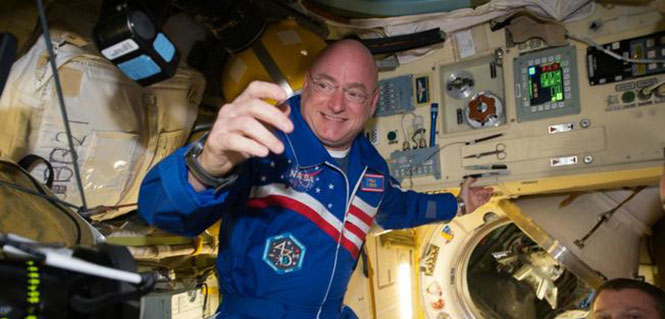
NASA astronaut Scott Kelly floats aboard the International Space Station after the hatch opening of the Soyuz spacecraft Mar. 28, 2015. (Photo: NASA)
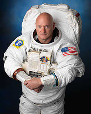
One of the more well known space shuttle command pilots is Commander Scott Kelly, who as I write this is well into his ninth month aboard the International Space Station (ISS). He has three more long months to go before he returns home to a hero’s welcome and a battery of medical tests to determine how longevity in space affects the human body by comparing him to his astronaut twin who remained Earth-side during the same 12-month period. You know Einstein’s general theory of relativity, divided by telomere length and all sorts of quantum mechanics and medical technology. Talk about being poked and prodded.
Scott Joseph Kelly (born Feb. 21, 1964) is an American astronaut, engineer and a retired U.S. Navy Captain. A veteran of three previous missions, Kelly was selected in November 2012 for a special year-long mission to the International Space Station, which began in March 2015.
Scott Kelly is interesting for one more record he created during his time as a shuttle commander and shuttle command pilot. He flew the first-ever space shuttle GPS approach on Aug. 21, 2007, on STS-118. When I first heard about this feat, I thought it would be interesting to talk with Scott about it, and I made plans to do so upon his return from the ISS in March 2016.
However, through the marvels of instant messaging and the good graces of my friend Joe Rolli at Harris Corporation (nee Exelis, nee ITT) I was put in touch with Scott Kelly.
We conducted our brief interview electronically with nary a glitch even though Scott is hurtling around the Earth in low Earth orbit at a speed of approximately 17,150 miles per hour (about 5 miles per second). This means that as Scott orbits the Earth, he experiences a sunrise once every 92 minutes for a total of 5,634 sunrise events during his year on orbit.
Relatively, however, compared with the speed of electrons or light, which travel at 670,616,629.4 mph in the vacuum of space, Scott and I — who are traveling at a differential of 17 orders of magnitude compared to electrons — are essentially standing still. So the seemingly huge speed differentials makes little or no difference. Again Einstein, Newton, Schroedinger and probably his cat, if alive, would beg to differ on a technicality, but for our intents and purposes, I stick by my statement.
Here’s how that interview went. I want to publicly thank Scott for taking the time out of an incredibly busy schedule to talk with us about the importance of GPS and the space shuttle. Scott currently serves as Commander of the ISS on the one-year mission. In October 2015, he set the record for the total amount of days spent in space by an American astronaut — 382. As this article goes to press, Scott has spent more than 445 days in space.
NASA astronaut Scott Kelly has been aboard the International Space Station since March as part of an endurance mission to test the effects of long-term exposure to space. In this July 12, 2015, photo he poses for a selfie in the “Cupola” of the ISS. (Photo: NASA)
(Don: Don Jewell, GPS World Defense Editor; Scott: Astronaut Scott Kelly)
Don: Scott, thanks for taking the time out of your busy schedule for our questions concerning GPS and the first space shuttle approach made using that technology, which you flew several years ago now.
Scott: This was eight years ago and I don’t have notes here, so this is my best quick effort.
Don: Why did NASA decide to approve GPS approaches for the space shuttle, and why were you chosen to fly the first one? I would assume that your experience, safety, approach options and flexibility would play a part here.
Scott: TACAN was going away. I wasn’t assigned to STS-118 because of this. This was a secondary DTO or Developmental Test Objective.
Don: Was a GPS approach after that first landing always an option?
Scott: GPS approach is kind of a misnomer. We incorporated GPS into the navigation state [for the space shuttle] from about Mach 5 [five times the speed of sound] until we transitioned to a microwave landing system on final.
Don: Were the certified and validated GPS approaches unique, or did they mimic current approaches such as ILS or VOR/DME?
Scott: Actually, Don, they have little to do with the GPS approaches aircraft fly.
Don: Were there both precision and non-precision GPS approaches? Do you remember the approach speeds and critical points in the approach? Can you discuss them? Since some of the alternates around the globe are in fairly primitive locations, did GPS make them more accessible and actually provide more alternates?
Scott: Again, GPS was used to update our navigation state. On an approach to a runway without an MLS (Microwave Landing System), GPS would have been our primary navigation source to the ground, but its not like we would be looking at an approach plate.
Don: What were the minimums for a GPS approach, before you could start a descent profile for a GPS (aided) approach and landing?
Scott: Actually, Don, our weather minimums were pretty restricted before we could start the de-orbit burn [while still in orbit]. Ceilings of 5,000 feet I think.
Don: At what point in your descent profile were you or NASA required to make a decision about your landing location and alternates? And, related to that, was there a typical point during the descent profile where you were committed to a landing location and could not choose an alternate? How far was that from your landing site nominally?
Scott: Legally you could re-designate after the de-orbit burn to an alternate [landing] site, but this would be in a very critical situation and was never done. Basically, when we did the de-orbit burn, we were essentially committed to landing at the chosen airfield.
Don: In an emergency, were you able or authorized to land at an alternate that did not have an advance NASA team in place, and were you able to fly the space shuttle totally manually or were computers always involved for stability?
Scott: Yes, and computers were always involved.
Don: Many modern fighters are inherently unstable. When the last computer fails, ejection is the only option. How did this apply to the space shuttle?
Scott: We were [essentially] fly by wire…the shuttle can’t fly without at least the backup flight control system (FCS) computer. Nominally, we have four FCS computers online.
Don: Since aerodynamically you were essentially flying the world’s fastest and highest flying glider, at what point were you committed to a landing site? What discretion as the Pilot in Command did you have, or was it all up to NASA headquarters?
Scott: When you did the de-orbit burn, you were committed to a landing attempt somewhere. If you had communications with the Mission Control Center (MCC), they decided where you would land. [With] no communications, it is up to the commander in an emergency.
Don: The space shuttle exceeded the speed of sound by a factor of 25 in the Earth’s atmosphere (Mach 25) on approach. What were the handling characteristics when this occurred? While there was obviously a sonic boom, where there any handling anomalies that required manual inputs from the pilot in command?
Scott: There was a little buffeting — sort of like running off the road in a pickup truck.
Don: Speaking of alternates, if your landing gear failed to deploy, or you had an indication that there was a gear malfunction, where you able to land on alternate surfaces such as grass or sand? Most importantly, in your opinion, would the shuttle and crew have survived a water (ocean or lake) landing? And were these alternate landing sites planned for or simulated to any high degree of fidelity?
Scott: The simple answer is you would try and bailout, but of course crash, if you had no choice.
Don: Finally, your comments. What was it like to pilot the space shuttle, and what did having a GPS approach available mean to you?
Scott: It was a privilege. GPS allowed us to continue to fly the space shuttle as legacy systems like TACAN were retired.
Don: Thank you so much for your time. If you have some comments concerning your current one-year experiment aboard the ISS, that would be great.
Scott: Sure, Don. I am currently a little over 270 days into my one-year flight aboard the ISS and going strong. Plus, to bring this all back to GPS, I can definitely say that GPS is working well on the International Space Station. We also have a Garmin GPS in the Soyuz, which we would break out in an emergency situation, and use a handheld satellite phone if we had an off-nominal landing, to tell people where we were.
The International Space Station. (Photo: NASA)
Space Station and GPS
It is a good thing the GPS receivers on the ISS are working as well as they are. Since 2002, they have been the primary means for determining attitude, position, speed and universal coordinated time reference on the ISS. The GPS position of the ISS, which moves at five miles per second, is accurate to within 10 meters and is updated continuously.
Previously, according to NASA, the station’s position was determined using ground tracking and other techniques. That information was considered to be adequate if not overly accurate, as it was updated just once a day. Just before an update, the actual and propagated position of the station, the ephemeris, could differ by as much as 10,000 meters.
Specifically, the ISS uses the GPS position and velocity solution as the ISS navigation state. The ISS’s attitude determination filter combines the GPS receiver attitude information with ring laser gyro data available from the ISS rate gyro assembly (RGA) to produce the ISS attitude solution.
Today, continuous accurate knowledge of the space station’s location also keeps it safely out of the path of wayward space debris.
So now you know something about sailplanes, combat gliders, the U.S. space shuttle, the ISS, Astronaut Scott Kelly and how they are all affected by GPS. Even more importantly, I hope this column reinforces for you the ubiquity of the Global Positioning System.
GPS is the world’s time keeper and primary global time distribution system. GPS time synchronizes networks, computers, communications and any number of other devices, from Apple iWatches to undersea navigation, to systems used by private pilots, airlines, spacecraft and astronauts in deep space. You name it: If it uses time, chances are GPS time is the provider, with an incredible stability of 1E-14.
Indeed, you should think of GPS as an enabler. It enables so much of our technology today that it would be difficult to imagine living without it. Contrary to popular belief, even in the U.S. government, GPS is robust and reliable and becoming more so every day. Just think about it: GPS tells us when and where we are, how to get where we are going, and whether or not we are late. An amazing system, brought to you free of charge by the United States Air Force.
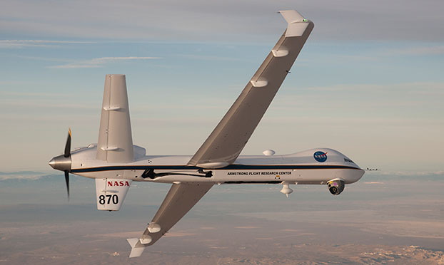
NASA’s Ikhana is being used to test a system that will allow uncrewed aircraft to fly routine operations within the National Airspace System. (Credit: NASA)
NASA plans to install a Locata network (LocataNet) as the core positioning technology for safety-critical unmanned aerial systems (UAS) research at its Langley Research Center in Hampton, Va., according to an announcement by Locata.
NASA Langley is tasked with performing rigorous and repeatable scientific evaluation of new UAS safety and technology concepts under development. The LocataNet will provide high-precision non-GPS-based positioning, navigation and timing (PNT) that is essential for this work. Known for its long history of aeronautics research, NASA Langley is a key center for UAS research and development. In June, one of Langley’s unmanned hexacopters (a drone with six rotors) delivered medical supplies to a clinic, the first such delivery by an unmanned drone.
Locata’s centimeter-accurate positioning will now assist NASA to develop and improve flight-critical technology systems that support air transportation safety, efficiency and performance. Langley’s extensive state-of-the-art facilities will be further enhanced with the installation of the LocataNet.
The NASA LocataNet is scheduled to be installed and commissioned before the end of 2015. Locata will supply the LocataLite Transmitters and Locata receivers required by NASA for the installation. Aviation-quality Locata antennas, developed by Cooper Antennas (UK) and previously used by the U.S. Air Force in its own military LocataNets, will also be installed. Locata engineers will support the physical installation, ongoing training and the future technical support required by NASA Langley for this world-first UAS deployment.
Locata Corporation has invented new terrestrial positioning networks which function as local, ground-based replicas of GPS. These networks can be thought of as “GPS hotspots,” according to the company. Locata has amassed 146 granted patents to date protecting these innovations, with many more patents in the works.
Locata is currently shipping commercial systems to demanding and professional end users such as the USAF, NASA, Leica Geosystems, and many others. Locata enables their integration partners to extend GPS-like positioning coverage to modern industrial, commercial, consumer and government applications in areas where GPS is erratic, jammed or unavailable.
“Locata is proud and delighted to have received an order for NASA’s first LocataNet. Globally significant installations like this prove Locata’s new technology is delivering unprecedented levels of performance to many important new applications,” said Nunzio Gambale, Locata CEO. “As our technology roll-out begins to gain pace, the exceptional value Locata brings to next-gen mobile apps has attracted interest from players all over the world. In fact, our list of relationships is now looking like a roster of the world’s crème-de-la-crème. I honestly can’t think of a better or more prestigious name than NASA to add to our growing partner list.”
“Our team is savoring the opportunity to work alongside NASA engineers and we’re excited that Locata will help advance the safety-critical performance of Unmanned Aerial Systems,” he continued. “Almost all future mobile devices or machines, be they on the road, in the air, on a mine site, in a port, in a warehouse, in your mobile phone, or part of the inevitable Internet of Things — all of them are critically dependent on pervasive, reliable, high-accuracy positioning. Locata is being leveraged into these next-gen systems because it’s clear that satellite-based solutions alone can no longer deliver what’s required. Soon, as we bring miniaturized Locata transmitters and receivers to market, our innovations will enable even greater advances in cutting-edge consumer, commercial, and government applications.”
NASA Testing Program. As part of its UAS research, NASA is testing a system that would make it possible for unmanned aircraft to fly routine operations in United States airspace. Through the agency’s Unmanned Aircraft Systems Integration in the National Airspace System (UAS-NAS) project, NASA, General Atomics Aeronautical Systems, Inc. (GA-ASI) and Honeywell International, Inc., are flying a series of tests which began on June 17 and will run through July at NASA’s Armstrong Flight Research Center in California.
“We are excited to continue our partnership with GA-ASI and Honeywell to collect flight test data that will aid in the development of standards necessary to safely integrate these aircraft into the National Airspace System,” said Laurie Grindle, UAS-NAS project manager at Armstrong.
This is the third series of tests that builds upon the success of similar experiments conducted late last year that demonstrated a proof-of-concept sense-and-avoid system. The tests engage the core air traffic infrastructure and supporting software components through a live and virtual environment to demonstrate how a remotely piloted aircraft interacts with air traffic controllers and other air traffic.
“This is the first time that we are flight testing all of the technology developments from the project at the same time,” Grindle said.
This series of tests is made up of two phases. The first is focused on validation of sensor, trajectory and other simulation models using live data. Some of the tests will be flown with an Ikhana aircraft, based at Armstrong, that has been equipped with an updated sense-and-avoid system, as well as other advanced software from Honeywell.
Other tests will involve an S-3B plane from NASA’s Glenn Research Center in Cleveland, serving as a high-speed piloted surrogate aircraft. Both tests will use other aircraft following scripted flight paths to intrude on the flight path the remotely-piloted craft is flying, prompting it to either issue an alert or maneuver out of the other aircraft’s path. These flights will also conduct the first full test of the traffic alert and collision avoidance system (TCAS II) on a remotely piloted aircraft.
During the June 17 test, which lasted a little more than five hours, the team accomplished 14 encounters using the Ikhana aircraft and a Honeywell-owned Beech C90 King Air acting as the intruder. A second test was flown the following day, with a total of 23 encounters. The project team plans to fly more than 200 encounters throughout the first phase of the test series.
“Our researchers and project engineers will be gathering a substantial amount of data to validate their pilot maneuver guidance and alerting logic that has previously been evaluated in simulations,” said Heather Maliska, Armstrong’s UAS-NAS deputy project manager.
The second phase of the third test series will begin in August and will include a T-34 plane equipped with a proof-of-concept control and non-payload communications system. It will evaluate how well the systems work together so that the aircraft pilots itself, interacts with air traffic controllers and remains well clear of other aircraft while executing its operational mission. The aircraft, which will have an onboard safety pilot, will fly an operationally representative mission in a virtual airspace sector complete with air traffic control and live and virtual traffic.
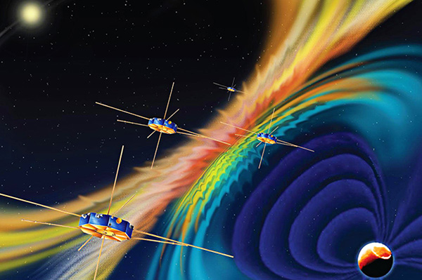
The four MMS spacecraft host the highest ever operational GPS receivers in space. (artist’s rendition, credit: NASA)
Editor’s Note: See additional coverage of the MMS mission here.
September Marks Start of Magnetosphere Mission, but Navigators Already Perform
A NASA mission to explore magnetic reconnection also made GPS history this spring. The Magnetospheric Multiscale (MMS) mission, led by NASA’s Goddard Space Flight Center in Greenbelt, Md., is flying four identically equipped spacecraft in a tight formation to take measurements 100 times faster than any previous space mission.
Each of the four spinning MMS spacecraft — roughly the size of a ballpark once eight booms deploy — is equipped with 25 sensors and other components provided by more than 40 partner institutions in the U.S., Europe and Japan. One key component is a GPS receiver dubbed Navigator.
Magnetic reconnection is a fundamental, yet poorly understood process.While reconnection occurs throughout the universe when magnetic field lines within plasma connect and disconnect, it can impact our technological society, since it drives virtually all space weather events that can disrupt low-Earth-orbiting spacecraft and lead to GPS, communications and power blackouts on Earth.
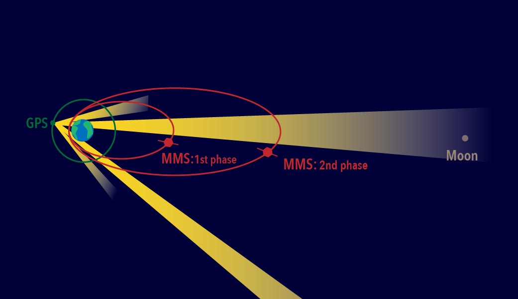
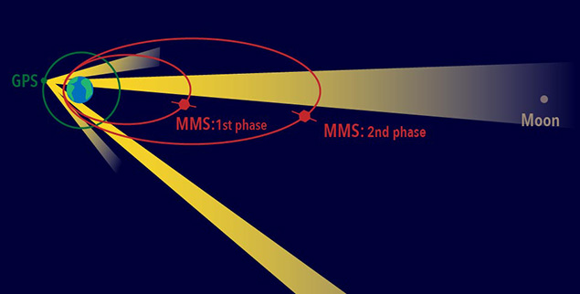
During the mission’s first phase, which begins in September, the spacecraft will travel through reconnection sites on the sun-side of Earth, where the orbit extends out toward the sun to around 47,500 miles. One year later, ground controllers will move the spacecraft to Earth’s night-side or magnetotail where the magnetic fields also reconnect — an orbit that extends away from Earth to almost 99,000 miles, nearly halfway to the moon.
However, science operations can’t begin before the four move into a highly elliptical orbit and assume their pyramid-shape formation that places the spinning spacecraft just 6.2 miles apart. It required a breakthrough to accomplish such an exacting formation, and the Goddard-developed Navigator GPS provided the solution.
Begun in the early 2000s as an enabling technology for MMS-type missions, the Navigator receiver and associated algorithms can quickly acquire and track GPS radiowaves even in weak-signal areas well above GPS’s 30-plus-satellite constellation positioned about 12,550 miles above Earth. In addition to continuously tracking weak signals, the Navigator also must operate as the spacecraft spin at three revolutions per minute. As a result, each MMS satellite is equipped with two Navigator receivers (primary and redundant), with four antennas placed around the perimeter of each, assuring continuous contact with the tracked GPS satellites
“Spinning adds a whole new dimension to trying to figure out where you are,” said Ken McCaughey, MMS GPS Navigator Product Development Lead at Goddard. “As the spacecraft rotates we have an algorithm running that allows us to hand off from one antenna to the next without losing the signal.”
Robust Receivers. To the satisfaction of the technology’s architect, Goddard technologist Luke Winternitz, the receivers have proven very robust. Shortly after the GPS receivers were powered on after the launch, Navigator became, at more than 43,500 miles above Earth’s surface, the highest ever operational GPS receiver in space. “We’re tracking up to 12 GPS satellites at maximum altitude and track on average about nine,” Winternitz said. “We’re really excited about their performance so far.”
Even if the receiver were to lose all GPS signals for part of the orbit, Navigator is specifically designed to handle such dropouts. By gathering as many observations as possible, integrated software called GEONS — Goddard Enhanced Onboard Navigation System — can still compute the orbit by incorporating additional information including drag force, gravity, and solar radiation pressure.
The red ellipses show the MMS orbit paths during the first and second phases of the mission. Each spacecraft uses GPS signals — which come from satellites situated along the green circle shown surrounding Earth — from the far side of Earth to track its position. (Credit: NASA/MMS)
This system will be even more important during the second phase of the MMS mission when the orbit will double in size and travel all the way out to 95,000 miles from Earth.
“It’s going to be very interesting to see how far out MMS can still receive signals,” said Mission Deputy Project Manager Brent Robertson. “But Navigator has already far exceeded expectations.”
Almost all activities associated with operating the mission depend on where the satellites will be positioned a few days hence. That includes everything from determining the best time to downlink telemetry and scientific data to calculating when ground controllers would command the firing of the satellites’ onboard thrusters, which move and help maintain their orbital formation — an exercise that will happen at least once every couple weeks.
“I think there’s a good chance we’ll end up being able to use GPS and save us some of the expense of using ground observations,” Robertson said.
While Navigator technology and GPS receivers were previously flown for testing and to help navigate a low-earth-orbit mission, this is the first time that the complete Navigator package has been used to actively navigate a high-altitude mission. Now that the team knows it works so well, Navigator can be used for other missions that travel in similar high orbits.
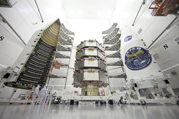
The four MMS observatories are processed for launch in a clean room at the Astrotech Space Operations facility in Titusville, Fla. The MMS mission launched March 12, 2015. (Credit: Ben Smegelsky/NASA)
Navigator Highlights
At the highest point of the MMS orbit, at more than 43,500 mile above the surface of the earth, Navigator set a record for the highest ever reception of signals and onboard navigation solutions by an operational GPS receiver in space.
At the lowest point of the MMS orbit, Navigator set a record as the fastest operational GPS receiver in space, at velocities over 22,000 miles per hour.
At the farthest point in its orbit, some 43,500 miles away from Earth, Navigator can determine the position of each spacecraft with an uncertainty of better than 50 feet.
The red ellipses show the MMS orbit paths during the first and second phases of the mission. Each spacecraft uses GPS signals — which come from satellites situated along the green circle shown surrounding Earth — from the far side of Earth to track its position. (Credit: NASA/MMS)
Editor’s Note: See more about the MMS mission in our August issue. The article is also posted here.
News courtesy of NASA
After years of hard work building a spacecraft, a mission team anxiously awaits after a launch — will the instruments they’ve crafted all work as well as planned? This is all the more true when flying new hardware, such as the onboard navigation tool on the four spacecraft that make up the Magnetospheric Multiscale, or MMS, mission, which launched on March 12. This navigation system had never before flown on a spacecraft with an orbit traveling so far from Earth — but if it worked, it would provide the precision navigation needed for MMS.
And the results are now in: Not only has the MMS Navigator system exceeded all of the team’s expectations, it has set the record for the highest GPS use in space.
At the highest point of the MMS orbit, at more than 43,500 mile above the surface of the earth, Navigator set a record for the highest-ever reception of signals and onboard navigation solutions by an operational GPS receiver in space.
At the lowest point of the MMS orbit, Navigator set a record as the fastest operational GPS receiver in space, at velocities over 22,000 miles per hour.
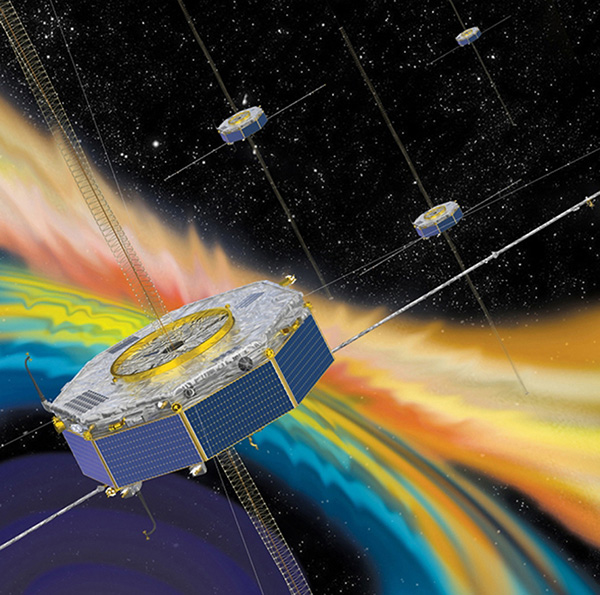
A precise tracking system is crucial for MMS, which requires extremely sensitive position and orbit calculations. The four spacecraft must fly in a tight pyramid formation to gather science data as they move through Earth’s magnetic environment. The formation is required to obtain three-dimensional observations of a phenomenon called magnetic reconnection that occurs when magnetic fields from the sun connect and disconnect with magnetic fields of Earth, which can allow energy and solar material to funnel into near-Earth space. With its instrument booms deployed, each spacecraft is the size of a baseball field — while flying as close as six miles from each other.
Artist’s concept of the MMS (courtesy of NASA).
“Demonstration airplanes like the U.S. Navy’s Blue Angels fly in closer formations, but those planes are also much, much smaller and the pilots are always controlling the movements,” said Brent Robertson, deputy project manager for MMS at NASA Goddard Space Flight Center in Greenbelt, Md. “We have four giant spacecraft each with its own unique orbit that we make maneuvers on about every two weeks. It’s quite challenging to control this formation.”
Tracking spacecraft can be done by radar stations from the ground, but it’s much more expensive and takes longer than an inflight system. However, using GPS as is typically done on Earth by such things as cars, boats and smartphones isn’t nearly as simple for something like MMS. For one thing, the bulk of its highly-elliptical orbit occurs above where the GPS transmitters orbit. So MMS must have specialized, extremely sensitive receivers to capture GPS signals transmitted from the far side of Earth. In addition the MMS spacecraft spin; each one makes three revolutions per minute.
“Spinning adds a whole new dimension to trying to figure out where you are,” said Ken McCaughey, MMS GPS Navigator Product Development Lead at Goddard. “We have four GPS antennas on each spacecraft. As the spacecraft rotates we have an algorithm running that allows us to hand off from one antenna to the next without losing the signal.”
In the first month after launch, the MMS team began turning on and testing each instrument and deploying booms and antennas. During this time, the team compared the Navigator system with ground tracking systems and found it to be even more accurate than expected. At the farthest point in its orbit, some 43,500 miles away from Earth, Navigator can determine the position of each spacecraft with an uncertainty of better than 50 feet.
What’s more, the receivers on MMS have turned out to be strong enough that they consistently track transmissions from eight to 12 GPS satellites — excellent performance when compared to pre-flight predictions that there might be frequent drop outs during each orbit.
Even if the receiver were to lose all GPS signals for part of the orbit, Navigator is specifically designed to handle such dropouts. By gathering as many observations as possible, integrated software called GEONS — for Goddard Enhanced Onboard Navigation System — can still compute the orbit by incorporating additional information including drag force, gravity, and solar radiation pressure.
This system will be even more important during the second phase of the MMS mission when the orbit will double in size and travel all the way out to 95,000 miles from Earth.
“It’s going to be very interesting to see how far out MMS can still receive signals,” said Robertson. “But Navigator has already far exceeded expectations. I think there’s a good chance we’ll end up being able to use GPS and save us some of the expense of using ground observations.”
While Navigator technology and GPS receivers were previously flown for testing and to help navigate a low-earth-orbit mission, this is the first time that the complete Navigator package has been used to actively navigate a high-altitude mission. Now that the team knows it works so well, Navigator can be used for other missions that travel in similar high orbits.
The European Space Agency (ESA) on June 23 successfully launched its Sentinel-2A satellite, the second satellite to be launched in Europe’s Copernicus environment monitoring program. Above is a video of the Sentinel 2A lift-off.
“We are very pleased to have such a talented new player join the team in watching Earth from space,” said Suzette Kimball, acting U.S. Geological Survey (USGS) director. “The aptly named Sentinel mission will help sharpen our focus on changes in Earth systems and contribute further insight to a great many global challenges at international to local scales, including food security, forest and wildlife conservation, and disaster response.”
NASA has published a comparison of Sentinel-2A and Landsat bandwidths.
Sentinel-2 imagery is expected to supply valuable parallels and counterparts to Landsat imagery provided by the United States. Before Sentinel-2A launched, USGS and ESA staff worked together at length to ensure that Sentinel-2 data would be as compatible as possible with Landsat data.
First launched by NASA in 1972, the Landsat series of satellites has produced the longest, continuous record of Earth’s land surface as seen from space. Landsat images have been used by scientists and resource managers to monitor water quality, glacier recession, coral reef health, land use change, deforestation rates, and population growth.
Landsat is a joint effort of USGS and NASA. NASA develops remote-sensing instruments and spacecraft, launches the satellites, and validates their performance. USGS develops the associated ground systems, then takes ownership and operates the satellites (since 2000), as well as managing data reception, archiving, and distribution. Landsat data were made available to all users free of charge under a policy change by the U.S. Department of the Interior and USGS in late 2008.
Sentinel-2A in the gantry before launch.
“We are also pleased that a free and open data policy has been adopted for users of Sentinel data,” Kimball added. “Free, open access to Landsat and Sentinel-2 data together will create remarkable economic and scientific benefits for people around the globe.”
Designed as a two-satellite constellation — Sentinel-2A and -2B — the Sentinel-2 mission carries an innovative wide swath high-resolution multispectral imager with 13 spectral bands. However, it will not fully duplicate the Landsat data stream, which includes thermal measurements. Sentinel-1A, a satellite with radar-based instruments, was launched April 3, 2014.
Once it is fully operational following several months of on-orbit testing, Sentinel-2A alone could provide 10-day repeat coverage of Earth’s land areas. With Sentinel-2A data added to the eight-day coverage from Landsat 7/8 combined, users can look forward to better-than-weekly coverage at moderate resolution. Repeat coverage capabilities will further increase with the planned launch of a second Sentinel-2 satellite (Sentinel-2B) next year.
Drone experts will join with those from the medical field in a demonstration July 17 in Wise, Va. The event, “Let’s Fly Wisely,” aims to show how unmanned aerial systems (UAS) can alleviate the problem of health care access while creating economic opportunity for communities.
Many people in Virginia and across rural America are beyond reach of essential health services and basic supplies, ranging from bandages to medicine, according to event organizers. The drones will deliver essential medical supplies to an annual medical clinic held at the Wise County Fairgrounds every summer, organized by Remote Area Medical (RAM) USA and the Health Wagon.
At the clinic, thousands of medical specialists provide free eye, dental and health care services to people in urgent need, in what event organizers say is the largest free health care outreach in the nation.
The UAS used for the demonstration will be a completely autonomous rotorcraft, designed by Flirtey, capable of delivering small payloads of drugs and medical equipment to isolated areas, and a larger, fixed-wing aircraft operated by NASA Langley Research Center, capable of carrying up to 600 pounds of cargo.
The most urgent prescriptions will be provided from pharmacies located out of town, reports Startup Daily. To get the medicine to the community as soon as possible, the pharmacies will deliver them to their local airport, where they will be collected by NASA’s fixed-winged aircraft and flown to Lonesome Pine Airport. When the prescriptions arrive there, they will be loaded onto Flirtey drones and delivered to the Wise County Fairground. Flirtey drones are expected to deliver around 24 packages of prescription medication.
The FAA-approved research flights will put UAS technology to work for medical relief, to show how unmanned aircraft can help health professionals provide care more easily and efficiently, closing the gap between those who can offer medical help and those who need it most.
“In doing so, we will demonstrate the promise of a technology that offers a bright future for our youth — right here in Virginia, where Wise County is rapidly becoming a center for technology manufacturing and testing. We believe Let’s Fly Wisely is much more than a novel use of technology in healthcare. It is an example of the self-reliance, ingenuity and wherewithal of the American people and Virginians in particular,” organizers said.
The collaboration includes nonprofits, universities, corporations and government organizations, including Virginia Tech Institute of Critical Technology and Applied Sciences. The Federal Aviation Administration selected Virginia Tech in December 2013 as one of six national test programs to conduct research on integrating unmanned aircraft into the nation’s airspace.
Other partners include:
The Appalachian College of Pharmacy
Flirtey, Inc.
Health Wagon
The Mid-Atlantic Aviation Partnership
NASA Langley Research Center (pending approval of the Space Act agreement between NASA Langley Research Center and Virginia Tech)
Remote Area Medical
Rx Partnership
SEESPAN, Inc.
Wise County Economic Development
The video below shows how Australian start-up Flirtey delivers packages with its drones.