“Seen & Heard” is a monthly feature of GPS World magazine, traveling the world to capture interesting and unusual news stories involving the GNSS/PNT industry.
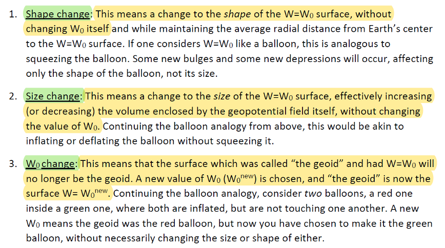
Photo: Alexey_Seafarer/iStock/Getty Images Plus
HOW BIG IS THAT BEAR?
Monitoring the weight of polar bears — an important health factor — usually means tranquilizing them from the air and lifting them with a tripod attached to a scale. However, technology might provide a non-invasive solution. Various zoos and sanctuaries are testing the accuracy of lidar scanners to measure the weight of polar bears, reports Geo Week News. The scans could be done using drones and mobile mapping equipment and techniques, according to Joel Cusick, a GIS specialist for the National Parks Service.
Photo: PaulFleet/iStock/ Getty Images Plus
SLIP SLIDING AWAY
Researchers used a combination of GNSS and interferometric synthetic aperture radar (InSAR) data from Sentinel-1 satellites to determine subsidence in
99 cities around the world between 2015 and 2020. Subsidence rates in Tianjin, Semarang and Jakarta exceed 30 mm per year. Even in mostly stable cities, areas are sinking faster than sea level is rising, with Istanbul, Lagos, Taipei, Mumbai, Auckland and Tampa sinking faster than 2 mm per year in some areas. Besides climate change, causes include groundwater extraction, mining, reclamation of natural wetlands, infrastructure projects and ecological disturbances. The study is published in Geophysical Research Letters.
Photo: NOAA Fisheries/Raymond Boland
FINDING NEMO
National Oceanic and Atmospheric Administration (NOAA) ocean mapping ship Rainier completed a five-month expedition to the Mariana Islands in September, combining mapping and charting with coral-reef ecosystem surveying. Collection of high-resolution mapping data in near real time improved the effectiveness of the traditional marine science data collection as the combined team mapped 4,000 square nautical miles of seabed and conducted 1,800 SCUBA dives. The data will improve navigation safety through updated NOAA nautical charts and increase understanding of coral reefs through the National Coral Reef Monitoring Program. Besides charts, the seabed mapping data supports marine protected areas, sustainable fisheries, and offshore wind siting — and, in the Marianas, is important for tsunami modeling.
Photo: mikulas1/iStock/Getty Images Plus
GRAVITY DOWN UNDER
An airborne gravity sensor is flying above 80,000 square kilometers of New South Wales (NSW), Australia, collecting data that will improve the accuracy of real-world heights from GNSS positioning to just a few centimeters. Data for the 18-month NSW Gravity Model project will be captured in five stages, starting in Western NSW. The resulting model is expected to enable better resource management, infrastructure planning and natural hazard preparation. It is also a critical building block for developing digital twins, replacing datasets that predate GNSS positioning.
Plus: Visual AI radar aids drone searches, and a drone is released into Hurricane Ian
Just when you imagine there couldn’t be any more twists and turns to the war in Ukraine, another one turns up. Some may recall that Estonian security forces caught an Estonian/Russian man trying to send drones to Russia. The Estonian government confiscated the shipment of DJI drones.
Now Estonia has donated those drones to Ukraine for use against Russia in the ongoing war.
Remember the drones we confiscated from a person trying to donate them for the Russian aggression in Ukraine? Well, these drones still made it to Ukraine. But the right way around and on the right side of the battlefront. https://t.co/No38Bbjkom
Some might say that this is an example of, “What comes around goes around.” Nevertheless, everyone respects Russia’s nuclear options…
Making Drones Smart
It’s all well and good that we have all shapes and sizes of battery- and gas-powered drones, ones that take off and land vertically (eVTOL) or horizontally (generally, fixed-wing). But how do we make them smart enough to complete tasks on their own?
Artificial intelligence (AI) could be the answer. Take the Boeing Loyal Wingman drone. It is being developed to fly autonomously alongside high-end fighters, and perhaps to control other drones flying nearby. Those tasks require AI, which is being incorporated into the capabilities of drone systems.
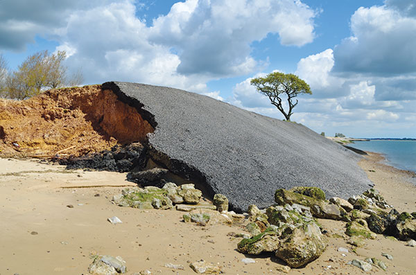
We also have immediate needs, such as search and rescue, security patrol and inspection (for commercial and military facilities, border and crowd control) and military intelligence, surveillance, target acquisition and reconnaissance (ISR/ISTAR). Along comes Sentient Vision Systems of Australia with a passive, software-based “visual radar” solution.
Sentient Vision Systems uses its digital AI processing with existing visual and infrared sensors. This combination can apparently surpass human and conventional radar capability to detect and track small moving objects.
Search and rescue at sea can be a really difficult task for people. It’s not surprising that a lot of lengthy searches end up with zilch. During a search, an aircraft flies from 20,000 feet down to 500 feet over the waves. If you have seen cabin video of air-sea searches in progress, with a searcher gazing out of the aircraft’s window for hours, straining to see something small bobbing in the sea below, it does seem like a herculean task.
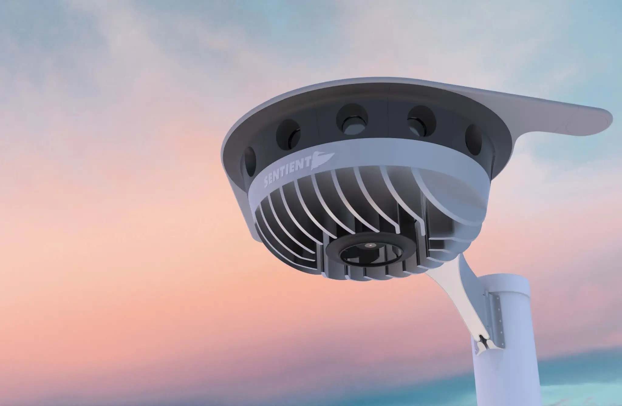
As an alternative, take a long-range (>55 nautical miles) drone, such as a Boeing/Insitu ScanEagle. Hook up the scanning search camera and high-resolution nose turret to the vidar (visual detection and ranging) processing.
Boeing/Insitu ScanEagle UAV with vidar pod. (Photo: Insitu)
As a result, you have an autonomous airborne system that can find a person in the water from a distance of about 1.7 nautical miles, and spot a ferry deck from ~30 nautical miles. Insitu claims that conventional radar systems cannot do this. In 12 hours it can search an area of about 13,400 square nautical miles.
Several such sorties might just have found an early trace of Malaysian Airlines Flight MH370 in 2014. The Boeing 777 with 239 people on board disappeared over the South China Sea 38 minutes after takeoff on a flight to Beijing. Over three years, long-range patrol aircraft covered 46,000 square miles before the search was abandoned.
During 2015 and 2016, pieces of the airplane began washing up on the shores of countries on the Western Indian Ocean. The search would probably not have been easy even for a fleet of ScanEagles, considering the logistics and the available range of the unmanned aircraft, but major incidents might find success with vidar-equipped UAVs.
Into the Eye of the Hurricane
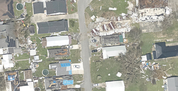
The devastation that Hurricane Ian wrought in Southwest Florida has been terrible. A shark swimming up a street in Fort Meyers illustrates the degree of flooding left from landfall of the category 4-5 hurricane.
Ian was the strongest hurricane to make landfall in the United States in decades, with extremely high winds and strong storm surge. I sat through the storm 75 miles to the North, and it was one scary hurricane even there. I can’t sympathize enough with the residents of Lee County, who only received a warning to evacuate one day before it hit them.
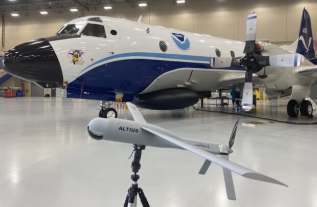
Nevertheless, the National Oceanic and Atmospheric Administration (NOAA) had its Hurricane Hunter Orion aircraft up to investigate on Sep. 28 as the storm came in from the Caribbean. Despite bad turbulence, the P-3 aircraft flew into the upper regions of the Hurricane and launched an Altus-600 27-pound drone into the eye at 4,500 feet. With a 275-mile range at up to 100 mph, the aircraft crew controlled the small drone, using it to collect data on wind speed, pressure, temperature and humidity.
The Orion P-3D Hurricane Hunter aircraft and the Altus-600 drone. (Photo: NOAA)
During the two-hour mission, the Altus drone flew into the eye wall, where winds of 187 mph were detected at altitudes between 2,300 and 200 feet. It’s not exactly clear whether the drone survived.
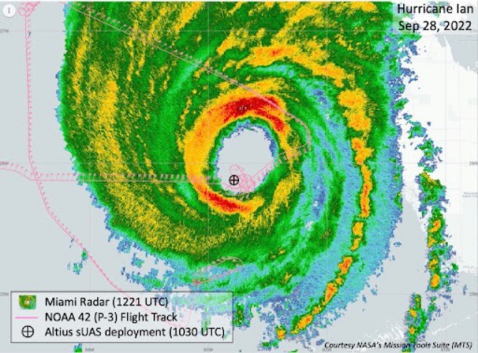
This radar image of Hurricane Ian shows the Altus release point. (Image: NOAA)
While information gathered may have assisted with the immediate forecasting for us Florida folks on the ground, the real scientific value comes from feeding the data into National Hurricane Center models for storm detection and analysis to keep us safer in the future.
Wrap up
To sum up, this month we saw drones destined for Russia sent to Ukrainian forces. Vidar artificial intelligence on Insitu ScanEagle drones promises huge gains for search and rescue. And, once again, a NOAA crew flew directly into the eye of a hurricane, this time releasing a drone to aid in gathering essential storm data.
Work supports climate change research, the 2020 Juneau landslide, and effects of the Exxon-Valdez oil spill
NV5 Geospatial marks its 65th year helping Alaska solve environmental and geospatial challenges, with new hydrospatial projects with the National Oceanic and Atmospheric Administration (NOAA), U.S. Geological Survey (USGS), Alaska Railroad Corporation, Alaska Department of Natural Resources, U.S. Fish and Wildlife Service and the U.S. Department of Agriculture.
“As climate change intensifies, so do the challenges that Alaska and its citizens face,” said Adam McCullough, NV5 Geospatial’s Alaska program manager. “From mapping the coastlines, to collecting lidar and imagery data to better understand geohazards and landslide risks, to mapping rivers, lakes and other surface water features, we are involved in critical projects across the state. We are proud to work side by side with national, state and local governments and agencies, as well as private corporations to facilitate climate-change informed decision making over the state’s valuable, unique resources.”
The following six projects provide a sampling of the work in which NV5 Geospatial has participated across the state:
Revillagigedo Topobathymetric Lidar and Imagery Mapping – NV5 Geospatial is working alongside state and federal partners on a multi-year program to map Alaska’s 66,000 miles of complex coastline. This work is part of a larger national shoreline mapping project being undertaken by NOAA to gather baseline data to update nautical charts, manage coastal resources, and define U.S. territorial limits.
The data collected also can support maritime trade and transportation, as well as wave and wind energy site selection. The data supports coastal resiliency efforts that include modeling sea-level change, storm surge, coastal flooding and pollution trajectories, as well as analysis and monitoring of critical habitats, developing land and marine GIS base layers.
The Alaska Railroad Corporation (AARC) Lidar Acquisition for Geohazards – AARC engaged Michael Baker and NV5 Geospatial to collect high-resolution topographic lidar and imagery data for analysis of geohazards, hydrology, engineering and landscape ecology across portions of its vast rail network in Alaska. NV5 leveraged its advanced combined low-altitude sensor solution (CLASS) mounted to a helicopter to simultaneously collect lidar, ortho-imagery and oblique images along the rail line that enables researchers to evaluate landslide and hydrological risks in areas of concern.
USGS 3DEP Juneau Landslide Lidar Study – In the aftermath of unprecedented rain events in Southeast Alaska in December 2020, the City and Borough of Juneau, along with Alaska Electrical Light & Power, partnered with the USGS to acquire and process 3DEP-compliant airborne topographic lidar data covering the Juneau landslide impact area. The USGS contracted NV5 Geospatial to perform the lidar survey that included acquiring extremely accurate lidar to USGS’s highest quality level specification.
The lidar data will support planning and landslide assessment to enable the reinforcement of critical infrastructure resources in the area. Project stakeholders are able to use this data along with existing lidar collected by NV5 Geospatial in 2013 to study how the landscape is changing in precise detail.
Alaska 3D Hydrography Program (3DHP) – The USGS, in partnership with state, local, and tribal governments and others, has embarked on a multi-year effort to enhance the mapping of rivers, lakes and other surface water features for the entire state of Alaska. Supporting that initiative, NV5 Geospatial has been repeatedly contracted by USGS to develop improved hydrography, covering 62,934 square miles to date.
NV5 Geospatial is leveraging the recently completed statewide interferometric synthetic aperture radar (IfSAR) coverage as the elevation data source to define drainages, impoundments and other hydrographic features in greater detail and accuracy. Once completed, the enhanced map data will be used to inform navigable waterways; conduct flood analysis; and delineate wetlands, fish habitat, recreational opportunities, coastal resiliency and more.
Exxon-Valdez Oil Spill, National Wetlands Inventory and National Hydrography Dataset – The U.S. Fish and Wildlife Service is leveraging grant funds to map wetlands and hydrography for areas affected by the 1989 Exxon Valdez oil spill. These areas include Kodiak Island, Afognak Island and the shorelines of Shelikof Strait in Alaska. Wetlands data are used by natural resource managers to promote the understanding, conservation and restoration of wetlands, while the hydrographic data supports scientific studies, cartography and natural-resource management associated with inland surface water features.
U.S. Department of Agriculture Aerial Orthoimagery Term Contract – NV5 Geospatial was awarded a large multi-year term contract to support aerial orthoimagery in Alaska. The contract has been used to acquire tens of thousands of square miles of high-resolution orthoimagery covering some of the nation’s largest national forests including Tongass and Chugach, as well as agricultural lands significant to the Natural Resource Conservation Service. These areas are in areas with some of the most challenging weather and terrain anywhere in North America and require aircraft on persistent standby to take advantage of the brief windows of opportunity to collect high-quality imagery.
High-resolution imagery geolocated by the sixth-generation Digital Sensor System (DSS) after Hurricane Ida. (Photo: NOAA)
Applanix, a division of Trimble, has been working with the National Oceanographic and Atmospheric Administration (NOAA) since the early 2000s to develop their response for emergency and coastal mapping activities. We discussed this collaboration with Joe Hutton, the company’s director of inertial technology, land and airborne products.
How has Applanix collaborated with NOAA regarding emergency response and coastal mapping?
Early on, we worked with them to develop a solution that allowed them to get out in the field and produce high accuracy map products with minimal touching of the data. In mid-2021, we delivered the next generation of this solution, or the DSS version six, which represents the culmination of everything learned over the years about how to produce imagery for emergency response, in terms of the types of collection, the types of imagery, and how to get it into first responders’ hands as quickly as possible.
At the heart of the system is our direct georeferencing technology. It’s a solution that allows us to assign the geographic location of every pixel of the digital imagery collected in the air. As soon as you land, you have the coordinates of every pixel, which means that you have a map that NOAA then pushes to the cloud for first responders to use in their emergency response efforts.
The collaboration consisted of Applanix working with Lead’Air to manufacture the next generation system that meets NOAA’s latest requirements. That’s what we delivered in 2021. Weeks after delivery, NOAA was called to respond to the hurricanes. They flew the new system with great success and were able to use it for their response.
What is your perspective on ground control points (GCPs) vs. direct georeferencing?
It is impossible to place GCPs in an emergency response when you cannot get on the ground. People who say they need GCPs do not really understand direct georeferencing. We’re having this debate even after 20 years of proving this technology. The NOAA system does not use GCPs and the map products are at centimeter level accuracy.
We use Trimble’s RTX technology, which enables centimeter-level GNSS positioning without base stations, which is important when the CORS or local RTN is unreliable due to a disaster. We have high accuracy inertial systems that get us the high accuracy orientation, so that we can go directly to ortho photos and ortho mosaics without running any triangulation or using GCPs in that process. That is a standard process these days. GCPs are only there for quality control if you want to deliver a final map product.
Did NOAA fly the mission with its own aircraft?
Yes, these are NOAA’s King Air or Twin Otter aircraft. The King Air aircraft is specifically outfitted for these types of emergency response and coastal mapping activities. The DSS system gets installed into the airplane and gets calibrated in terms of checking the system out for accuracy. Then it’s ready to fly the response. In the air, they collect the imagery over a flight path of interest to them. Then, it’s developed from raw imagery into JPEGs in the aircraft, and all the georeferencing data is logged with that imagery so that as soon as they land they can push a button and start to reference the JPEG imagery and push it to the cloud.
What are the components of your system?
What makes this system so unique is that it encompasses all the lessons learned over the years in terms of what NOAA needs to optimize for both their coastal mapping and their emergency response. It incorporates two pairs of color and near-infrared Phase One cameras that are configured in an oblique format with some overlap, forming a bowtie footprint on the ground.
You have 100% overlap of the color with the near-infrared and it’s on a high-performance stabilized mount that keeps everything perfectly level. The mount also has a special feature that enables the operators to rotate the cameras to go into nadir mode, mostly for traditional coastal mapping that requires stereo imagery. We were able to incorporate into a single system the requirements for both emergency response—where you want large coverage and obliqueness to look for damage—and nadir for coastal mapping.
Lead’Air built the sensor for you, on your specs, correct?
Yes, that’s correct. We’ve worked with Lead’Air for probably 20 years on flight management system (FMS) technology. They also have an amazing capability to build stabilized mounts and hardware systems. So, we decided to work together. We contracted them to implement some of their innovative hardware in this new design for us to deliver to NOAA. We contracted them to do all the manufacturing of the design and delivery to NOAA.
One of the quite innovative things that they did was to develop a new flight management capability that allows NOAA to fly ad hoc along highways or rivers, looking for damage. Traditionally, for aerial imagery you have to pre-flight plan trajectories. They designed an FMS that enables a pilot to fly a road or a river looking for damage without worrying about traditional block collections as with a more traditional FMS. So that feature further increases productivity. If you look at the most recent imagery at www.storms.ngs.noaa.gov you will see that it looks like spaghetti, not like blocks. That’s because they are following the roads and the rivers looking for specific damage.
Does the post-processing use your software?
Yes, it uses the POSPac MMS post processing software with POSPac Trimble Post-processed CenterPoint RTX correction service, allowing us to get that centimeter-level position accuracy, anywhere in the world with just an internet connection. You don’t have to worry about having a local base station—which, of course, if you’re in an emergency response situation, might not be there anyway. So, this is a very powerful way of getting global centimeter-level accuracy in real time, without having to worry about the ground-based GNSS infrastructure, that is, the local real-time network, that’s on the ground.
If you don’t have internet access, you can ship that data to the nearest place that does, right?
You could, however NOAA simply flies to wherever there is access. What takes the longest is to develop the imagery from the raw format to the JPEG format, because these are such large images. Doing that in the air saves an enormous amount of time. You have these JPEG-ready images that are compressed and can go right into the georeferencing process and make it really, really fast.
That’s a matter of computing power and smart software. What else did Lead’Air contribute?
This very efficient, fast image development process in the aircraft.
It sounds like it was a very integrated process between Applanix and Lead’Air. So, NOAA had the instrument mounted on their aircraft, their pilots did the flying, and then you processed the data?
No, NOAA’s team processes all the data. We just deliver the hardware and the software. They created the workflow software to push the data to their cloud environment.
NOAA uses this data to produce maps of the damage and highlight different situations and hazards?
Yeah. When these hurricanes go through, the first questions people have are “Where’s the damage? Are these roads passable? Did my house survive?” If you are doing response, you need to get teams in there. First, however, you need to know whether the roads are passable, so that you will not waste time going down a road that is not. So, the first thing they do is go up in the air and survey the main roads to push the imagery back, so that people can assess whether the roads are passable. Then they start to look for specific areas of damaged infrastructure, to triage where to put their resources. Then they ask “How do we manage disaster recovery?”
What lessons did you learn?
We are still learning about the power of the system, because these are Phase One 150 megapixel color cameras. It is such a powerful combination of sensors that they’re starting to look at different information they can get out of these things. They’re still learning new lessons in terms of what information can be useful for both the emergency response and the coastal mapping.
Ultimately, we’ll go to full ortho maps in the aircraft. That’s just going to be a matter of computational power. The holy grail would be to produce an orthophoto in the aircraft and radio it down to the ground in real time. Nothing prevents you from doing that now other than computational power and bandwidth. It’s not practical yet, but it will probably get there.
Do you have collaborations like the one with NOAA with any other major U.S. agencies?
We’ve worked extensively with NASA over the years. For example, we have worked with them on the ice bridge project. That is where they survey ice at both poles to measure its thickness and how global warming is affecting it. They use our system on that to do the georeferencing. We also work extensively with other branches of NOAA for their shoreline mapping from their ships. We have worked with them over the years to provide the georeferencing solution for the multibeam echo sounders to produce their nautical charts.
My April column addressed the vertical movement at the NOAA CORS Network (NCN). The values at the sites indicate the potential movement of marks in the area of the CORS. The rates are based on GNSS data and have an estimate of error associated with them.
As I mentioned in my previous column, I’m not sure how the National Geodetic Survey (NGS) will address the vertical movement effects in the new, modernized National Spatial Reference System (NSRS). That said, NGS will be monitoring the CORS and looking for trends to help describe the vertical movement at the CORS. These trends are an indication of what may be happening in that area.
As stated in previous columns, orthometric heights in NAPGD2022 will be defined through ellipsoid heights and a geoid model, for example GEOID2022. In addition to the movement of individual marks due to crustal movement, there are geophysical reasons for changes in the geoid that affect the orthometric height of a mark. Therefore, changes in the geoid model will be very important to users estimating orthometric heights using GNSS.
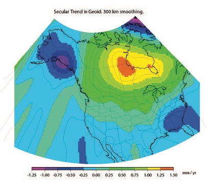
As stated in the NOS NGS 64 report, NGS has set a goal of maintaining geoid accuracy at 1 centimeter (1 standard deviation) in both absolute and differential geoid undulations. The box titled “Figure 13 from NOS NGS 64 Report” depicts an estimate of the secular change in the geoid. As indicated in the plot, the changes are very small, ranging from -1.25 mm/year to 1.5 mm/year.
What I find interesting is the small negative change in the southeastern United States. There are other drivers for geoid changes. This column will address some of these changes and what they mean to users.
Secular geoid change
Figure 13 from NOS NGS 64 Report (Image: NGS)
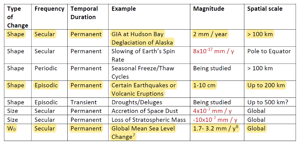
As mentioned in many of my articles, the new, modernized NSRS has a time-dependent component. This includes the geoid model. Table 5-1 from NOS NGS 64 report are examples of some of the physical processes being investigated by NGS to account for changes in the geoid. (See the box titled “Some of the geophysical drivers of geoid change.”)As mentioned in the NOS NGS 64 report, the magnitudes in red have already been determined to be too small for NGS to model. The examples highlighted in yellow have magnitudes that are significant and NGS will attempt to account for these changes to the geoid.
Table 5-1: Some of the geophysical drivers of geoid change
NGS classifies the changes in the geoid in three different groups: Shape Change, Size Change, and W0 Change. The box titled “The Groups of Geoid Change” provides NGS’s definition and explanation of the terms.
The groups of geoid change
NGS’s report on their Geoid Monitoring Service (GeMS) program provides figures that depict an estimate of the secular geoid rate trend based on the NASA GSFC mascon model. See the boxes titled “Estimate of Geoid Rate Over CONUS” and “Estimate of Geoid Rate Over Alaska.” For more details on GeMS, download the report NOAA Technical Report NOS NGS 69: A Preliminary Investigation of the NGS’s Geoid Monitoring Service (GeMS), and read my December 2019 Survey Scene column. The secular geoid rate trend is an example of the geoid changing its shape, but not the W0 value. What this means is that the local geoid undulations will change, but the overall size of the geoid will not.
Estimate of geoid rate over CONUS
Figure 32: Geoid rate over CONUS based on the GSFC mascon model [mm/yr] (Image: NOAA)Estimate of geoid rate over Alaska
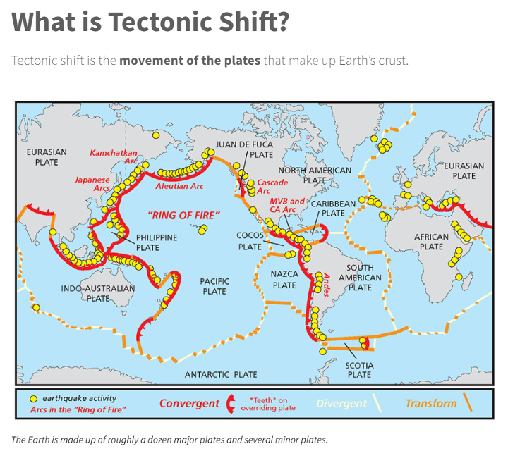
Figure 33: Geoid rate over Alaska from GSFC mascon model [mm/yr] (Image: NOAA)These changes in the geoid are fairly small values (+/- 1.3 mm/year), but they will accumulate over a decade. As previously stated, NGS’s goal is to maintain geoid accuracy at the centimeter level (1 standard deviation) in both absolute and differential geoid undulations. In my February 2022 column, I discussed how coordinates change because Earth’s surface is moving due to the movement of major tectonic plates. It’s fairly obvious how the tectonic shift affects horizontal coordinates, but earthquakes and volcanic eruptions can also cause large shifts in vertical coordinates.
In recent history, on May 18, 1980, geologists watched in awe as Mount St. Helens erupted in a gigantic explosion. After the eruption, the volcanic cone of Mount St. Helens had been completely blasted away; the peak, which was at an elevation of 9,677 feet (2,950meters) was changed to a horseshoe-shaped crater with an elevation of 8,363 feet (2,549 meters). Extreme crustal movements such as the Mount St. Helens eruption can change the shape of the geoid. As explained in my April 2022 newsletter, NGS understands this and is attempting to manage the changing coordinates by providing a time-dependent component to a mark’s ellipsoid height, but there is also a time-dependent component to the geoid that affects the mark’s orthometric height.
Ring of Fire
Image: National Ocean Service
The “Ring of Fire” map highlights earthquake activities around the world. As indicated in Table 5.1, earthquake or volcanic eruptions can change the shape of the geoid. Of course, they also can change the height of a mark due to crustal movement, which would typically be larger than the change in the geoid height. The amount of movement would be due to the size and magnitude of the event, but even small earthquakes could cause a change in the height of a mark located near the event. Earthquakes are occurring all over the world every day.
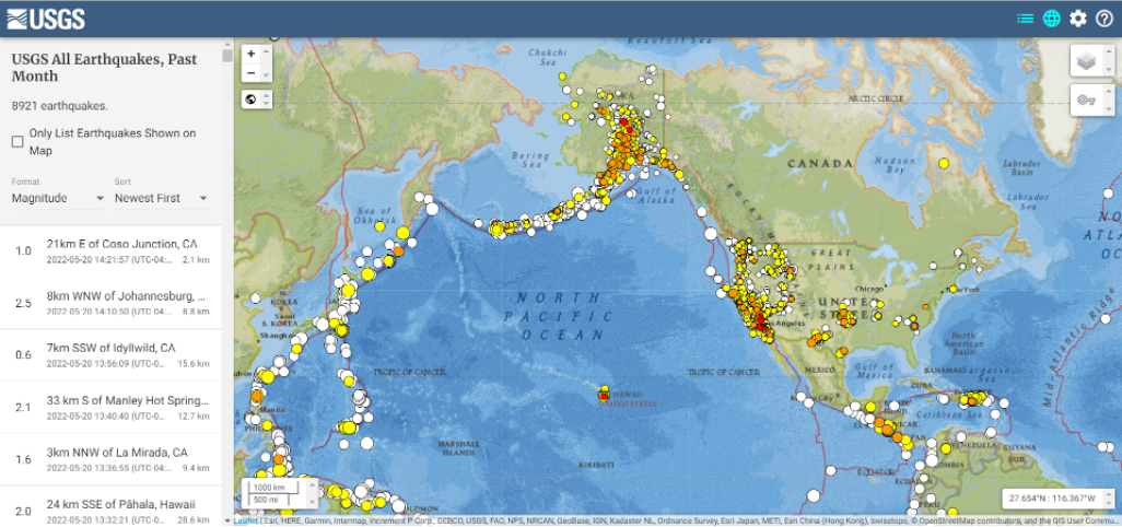
Earthquakes with large magnitudes are highlighted by news media outlets, but ones with smaller magnitude typically are not highlighted. The four figures below provide examples of earthquakes that have occurred over 30 days. This information can be obtained from the United States Geological Survey (USGS).
Earthquakes during the past 30 Days Date: May 20, 2022
Image: USGS
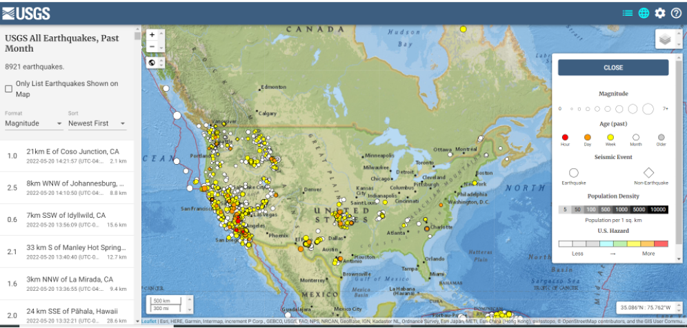
Earthquakes in the lower 48 during the past 30 days Date: May 20, 2022
Image: USGS
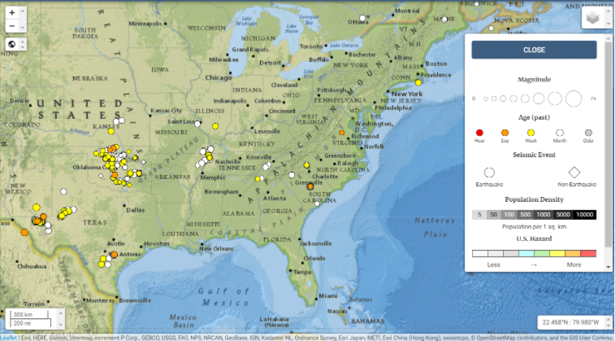
Earthquakes in eastern United States in the past 30 days Date: May 20, 2022
Image: USGS
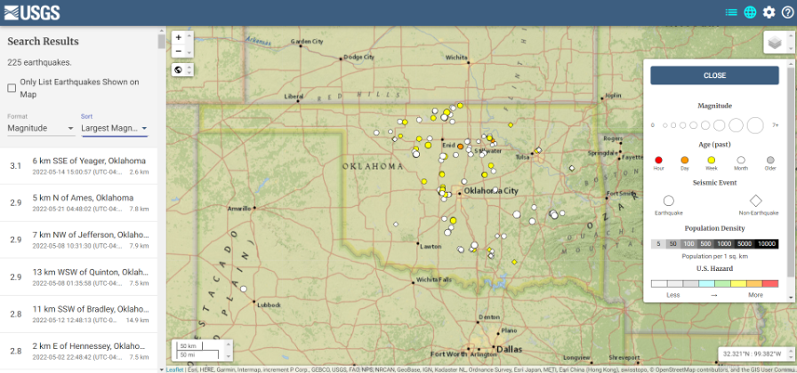
I found the large number of earthquakes that occurred in Oklahoma in just 30 days to be very interesting. This isn’t something that I thought occurred in the eastern region of the United States.
Earthquakes in Oklahoma during the past 30 days
Date: May 20, 2022
Image: USGS
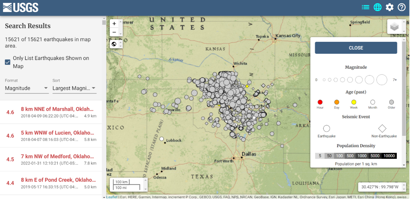
The image below depicts earthquakes that have occurred in Oklahoma in the past five years. They are fairly small in magnitude, but what is the cumulative effect on the geoid in the region, as well as changes to the orthometric heights of marks due to crustal moment in the region? This is why it is important for the new, modernized NSRS toimplement time-dependent coordinates.
Earthquakes in Oklahoma in the last 5 years Dates: 2017 to 2022
Image: USGS
To better understand the changes to the geoid, NGS performed a survey in Alaska to obtain geodetic data as part of its GeMS program. On May 12, 2022, Kevin Ahlgren, a geodesist at NGS, described in a webinar the observations collected and some of the results.
The presentation provided an overview of a field campaign performed in support of the GeMS program and a time-dependent geoid model. The campaign included static GNSS, relative gravity, and deflection of the vertical techniques on 50 stations in Alaska. The webinar was can be downloaded.
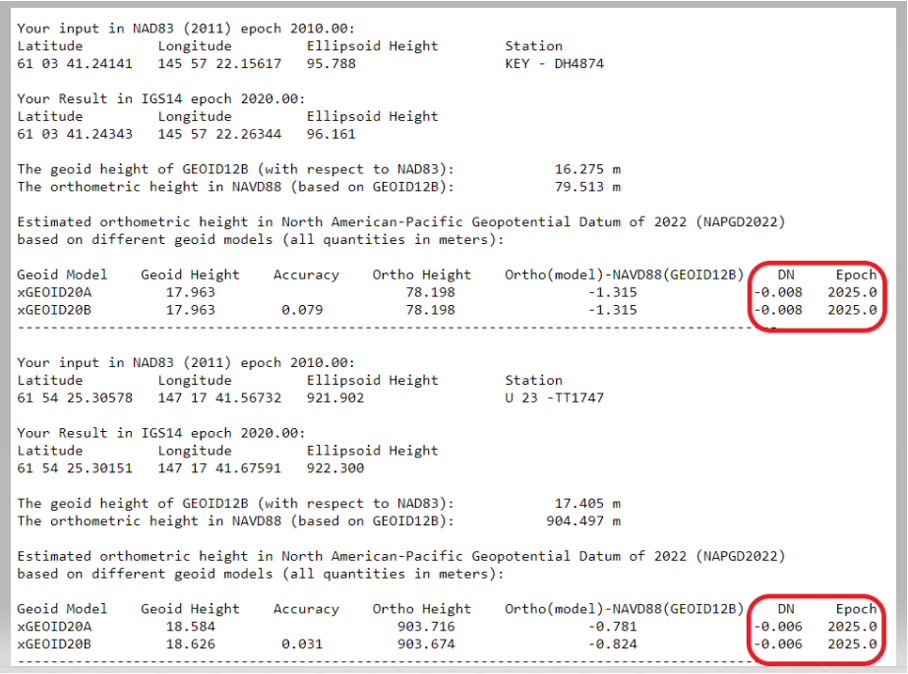
I encourage everyone to download the presentation. The change in the geoid due to geophysical drivers is small, but if the new, modernized NSRS is going to include time-dependent coordinates, then changes in the geoid must be accounted for. For demonstration purposes, NGS provides an example of the time-dependent geoid change in the xGEOID20 webtool. The box below, “xGEOID20 interactive computation output,” is an example of using this tool. The two stations are located in Alaska. As indicated in the output from the tool, the change in the geoid is 8 mm in five years. Again, NGS’s goal is to maintain geoid accuracy at the centimeter level (1 standard deviation) in both absolute and differential geoid undulations. These small changes can become significant over time.
xGEOID20 interactive computation output
Note: DN is the time-dependent geoid change computed between user inputted epoch (t) and t. (Image: NGS)
The last geoid change group that I’ll highlight has to do with the change in the gravity potential (W0) value that defines the model. The NOS NGS 64 Report states that the standing definition of the geoid, as adopted and used at NGS, is the following:
The geoid is the equipotential surface of the Earth’s gravity field which best fits, in a least squares sense, global mean sea level.
As stated in the NOS NGS 64 report, over a century of sea-level measurements imply that global mean sea level (GMSL) was rising at a rate of approximately 1.7 millimeters per year and was rising at a rate of 3.2 millimeters per year between 1993 and 2010 (IPCC, 2014). If NGS is going to define the geoid as theequipotential surface of the Earth’s gravity field that best fits, in a least squares sense, global mean sea level, then the geoid in the new, modernized NSRS must change when the GMSL exceeds a certain threshold.
Again, NGS’ goal is to maintain geoid accuracy at the centimeter level (1 standard deviation) in both absolute and differential geoid undulations. What this means is that as GMSL rises, the value of gravity potential which best fits to GMSL (called W0) will also change. In other words, the surface which was called “the geoid” and had W=W0in 2022 will no longer be the geoid. A new value of W0 (W0new) is chosen, and “the geoid” would now be the surface W=W0new.
So, what does this really mean to users? The NOS NGS 64 Report states on page 37:
“NGS and the Canadian Geodetic Survey have jointly adopted the value of 2.0 m^2/s^2 as the replacement threshold for a new geoid model (and new geopotential datum). This represents approximately 20 centimeters of GMSL (and thus geoid) rise. At the current rate of sea-level change of about +3 millimeters per year (IPCC, 2014), this means NGS expects to replace NAPGD2022 in approximately 60 to 70 years.”
Therefore, this should not be a major concern of users for a long time.
This column highlighted that orthometric heights in NAPGD2022 will be defined through ellipsoid heights and a geoid model, for instance GEOID2022; and therefore, changes in the geoid model will be very important to users estimating orthometric heights using GNSS. It briefly described the geophysical reasons for changes in the geoid that affect the orthometric height of a mark.
If NGS is going to meet the goal of maintaining geoid accuracy at 1 centimeter (1 standard deviation) in both absolute and differential geoid undulations, they will have to address changes in the geoid. The secular changes in the geoid, as indicated in Figure 13 in the NOS NGS 64 report, are very small, ranging from -1.25 mm/year to 1.5 mm/year. Once again, these are small changes to the geoid, but they will accumulate over time, and that is why NGS is including time-dependent coordinates in the new, modernized NSRS.
The largest source of error in GNSS positioning is the delay suffered by the signals as they pass through the ionosphere traveling from the satellites in orbit to receivers on or near Earth’s surface. That is because the ionosphere is full of free electrons stripped from atoms and molecules by ionization and this plasma refracts the signals, changing their speed. Normally, models compensate for this. However, geomagnetic storms wreak havoc on the free electrons in the ionosphere, making it difficult to accurately determine the signal delay.
That is why space weather matters for GNSS and for the myriad human activities that have come to depend on it.
So, here’s the good news. “On a scale of one to five, the geomagnetic storm on April 14 was a three,” Bill Murtagh told me. Murtagh is the Program Coordinator and Space Weather Forecaster at the Space Weather Prediction Center (SWPC) of the National Oceanic and Atmospheric Administration (NOAA). He was referring to the third rung of NOAA’s space weather scales, which were introduced to communicate to the public the current and future space weather conditions and their possible effects on people and systems.
NOAA has three space weather scales, one each for geomagnetic storms (G scale), solar radiation storms (S scale), and radio blackouts (R scale). The steps on the scales, ranging from “minor” to “extreme,” are analogous to those NOAA uses to classify hurricanes, tornadoes and earthquakes. They describe the environmental disturbances for each of these events and list their possible effects at each level.
Solar activity runs in 11-year cycles. A G5 event happens two or three times per cycle, and the last one was in October 2003, Murtagh told me. “I can only remember a handful of occasions over the past 20 years when ionospheric activity has significantly impacted users,” told me Gavin Schrock, PLS, manager of the Washington State Reference Network, a regional cooperative of GPS reference stations and data. According to Rick Hamilton, the GPS Information Analysis Team Lead at the U.S. Coast Guard Navigation Center, it “did not receive any reports of interference related to the geostorm” and “there was no significant increase in reports that we might attribute to geomagnetic activity.”
Now, the bad news. We are heading for a maximum in solar activity, expected to occur in 2025. The Sun is “already quite active,” Murtagh pointed out, and recently there has been an increase in the number of R1 and R2 storms. Solar coronal mass ejections (CMEs), which launch plasma and magnetic fields into space, also have become more frequent. When a CME hits the Earth, its collision with the Earth’s magnetic field causes a geomagnetic storm.
So, the GNSS constellations and the GNSS industry should be preparing now. Fortunately, improvements in GNSS software and receiver technology, plus corrections and integrity information and the much larger number of satellites, make us better prepared than we were during the last cycle. On the other hand, the stakes also are much larger, due to our ever-greater reliance on GNSS.
As a sailor, I rely on NOAA nautical charts and marine weather forecasts. GNSS users can thank NOAA for its space weather forecasts.
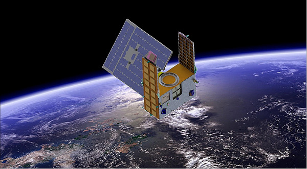
Artist’s illustration of a GNOMES satellite. (Image: Blue Canyon)
A new GNSS radio-occultation (RO) satellite is now in orbit. The GNOMES-3 — GNSS Navigation and Occultation Measurement Satellite — flew aboard the SpaceX Falcon 9 Transporter-4 rideshare mission on April 1 and was launched into a 646-km circular sun-synchronous orbit. The payload was powered on and operating nominally within four days of launch.
The GNOMES-3 was manufactured for PlanetiQ by Blue Canyon Technologies LLC, a wholly owned subsidiary of Raytheon Technologies. Using refracted GNSS signals, PlanetiQ can determine the density and moisture content of the atmosphere to improve weather predictions, helping improve NOAA weather models.
The GNOMES-3 joins GNOME-2 on orbit and is expected to achieve highly accurate GNSS-RO measurements using the fourth-generation Pyxis-RO sensor. PlanetiQ plans to launch more Pyxis-RO atmospheric and ionospheric sounding spacecraft in 2023. In all, PlanetiQ plans for a fleet of 20 GNOMES by 2024.
The GNOMES-2, launched in June 2021 on SpaceX’s Transporter-2 mission, produces more than 3,200 soundings of the Earth’s atmosphere and 5,000 ionosphere soundings per day with a large-aperture RO antenna that tracks all four GNSS constellations: GPS, Galileo, GLONASS and BeiDou.
The soundings have sufficient signal-to-noise ratio to indicate the location of the planetary boundary layer, as well as detect super refraction at the boundary layer and near the Earth’s surface. The higher quality GNSS-RO soundings, along with the associated lower troposphere assimilation tools, will be used to produce more accurate weather forecasting and hurricane tracking, and aid in energy, transportation and agriculture industries as well as serve as a climate record with its SI-traceable data.
Hurricane Ida assessment imagery and data are now available. Ida was a Category 4 Atlantic hurricane from Aug. 26 to Sep. 4. (Screenshot: NOAA)
Applanix, a Trimble Company, and the National Oceanic and Atmospheric Administration (NOAA) have collaborated to provide critical information to first responders in the wake of Hurricanes Henri and Ida.
Applanix’s high-accuracy direct georeferencing (DG) technology enabled NOAA to quickly collect aerial mapping imagery to
provide valuable disaster remediation information to first responders
demonstrate the value of mapping technology in preparing for and responding to emergency situations such as hurricanes, tornadoes and other disasters.
Within hours of Hurricanes Henri and Ida making landfall, NOAA’s National Geodetic Survey collected post-storm imagery using the latest generation Digital Sensor System (DSS). The sixth-generation DSS, designed and manufactured for Applanix by Lead’Air, is the most powerful to date, thanks to several new features introduced within the solution:
simultaneous full color and near-infrared image capture using high-performance Phase One iXM 100 MP NIR and 150 MP RGB cameras
option to fly the cameras in wide coverage oblique or traditional overhead (straight line down) mode for mapping with uninterrupted measurement
embedded Trimble AP60 GNSS + inertial OEM DG solution for mapping without the need for ground control or aerial triangulation
Applanix POSPac post-processing software featuring the Trimble post-processed CenterPoint RTX correction service (PP-RTX) for centimeter-level mapping without GNSS reference stations
in-air development of raw imagery to JPEG-ready files for creating map products immediately upon landing
Lead’Air’s X-Track flight management, which enables the system to be flown outside of planned flight lines to follow roads, rivers and coastlines.
Applanix’s DG technology suite provides direct GNSS inertial georeferencing, meaning that all pixels in the aerial images taken by NOAA are mapped at their exact location on the ground.
“We have worked with Applanix for nearly 20 years,” said Michael L. Aslaksen Jr., chief of the remote-sensing division, NOAA’s National Geodetic Survey. “The level of sophistication they bring to aerial imagery and mapping keeps our team at the forefront of the industry. Their customer support team is always open to new ideas, new innovations and doing whatever it takes to get the job done.”
First responders have access to this imagery and mapping within 24 hours via the cloud (as does anyone at storms.ngs.noaa.gov) and can map detailed response plans based on highly accurate data highlighting where the greatest need lies.
Access to this turnkey emergency response imagery is available to any federal agency, municipality, insurance company or other entity that depends on highly accurate information to plan for and recover from disasters.
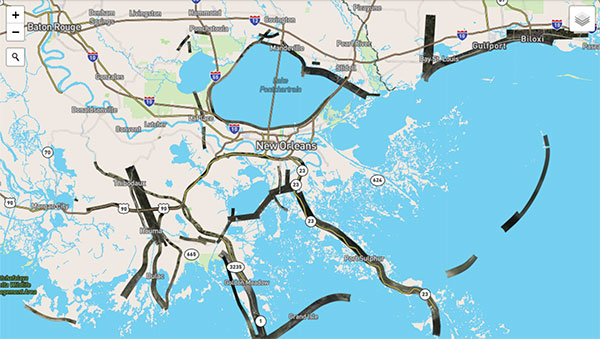
A new data source to help scientists better understand the ionosphere and its potential impact on communications and positioning, navigation and timing (PNT) is now available to the public.
The data, which was collected by sensors on GPS satellites in 2018, was released through a collaborative effort by Los Alamos National Laboratory and the National Oceanic and Atmospheric Administration (NOAA).
“Radio signals from satellite or ground-based transmitters can travel through the ionosphere or bounce off of it, so ionospheric conditions have the potential to disrupt communications depending on the density of electrons,” said Erin Lay, a remote-sensing scientist at Los Alamos who was a technical lead on the project. “This new set of data will help us better model and predict the behavior of the ionosphere and possibly improve the reliability of our communications and positioning, navigation, and timing services, which are critical for both everyday life and national security.”
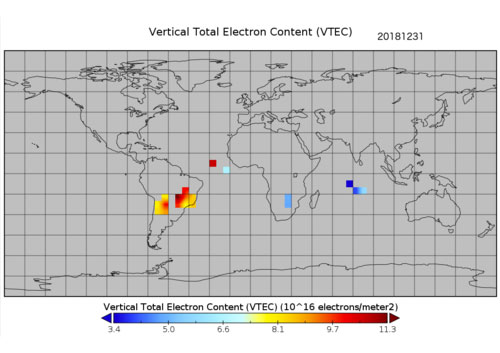
The ionosphere is the boundary between Earth’s atmosphere and space, stretching 40 to 250 miles above Earth’s surface. It is composed of tenuous atmosphere and charged particles (ions and electrons) that interact with traversing radio waves. The behavior of the ionosphere reacts to weather on Earth, such as thunderstorms, wind, and hurricanes, as well as space weather created by solar winds impacting Earth’s magnetic field.
“NOAA’s Space Weather Prediction Center (SWPC) serves a huge customer base interested in space weather effects on communications and GPS-reliant technologies,” said Bill Murtagh, program coordinator at SWPC. “We expect access to these Los Alamos data sets to improve the development, validation, and testing of models used at SWPC for characterizing and forecasting ionospheric disturbances.”
Preview graphic. (Image: NOAA)
The new data comes from unique measurements of lightning events, each of which produces a flash of radio waves that gets dispersed through the ionosphere before it is detected on satellite receivers. Each measured flash provides a snapshot of the ionospheric conditions at that instant, and many lightning measurements accumulated over time provide a unique view of ionospheric weather. This is the first-ever global set of ionospheric electron density data to use a naturally occurring source phenomena.
Before this release, the data available to feed ionosphere models was primarily from arrays of ground-based receivers, which are limited because they only monitor fixed locations. According to Lay, “the new data is gathered from lightning that happens all over the world and will give scientists the opportunity to study the ionosphere in ways previously not possible.”
The release of underutilized data sets was a priority established in the 2019 National Space Weather Strategy and Action Plan. Los Alamos processed the data from its radio-frequency sensors that are onboard GPS satellites and used for nuclear treaty monitoring, and then worked with a government interagency group, called the Space Weather Operations, Research and Mitigation (SWORM), to facilitate public release.
NOAA’s National Centers for Environmental Information will host the data on existing sites that serve terrestrial weather and space weather resources.
The ionosphere is shown in purple and not-to-scale in this image. (Image: NASA’s Goddard Space Flight Center/Duberstein)
The U.S. Department of Transportation (DOT) and the U.S. Coast Guard Navigation Center (NAVCEN) will hold the 61st meeting of the Civil GPS Service Interface Committee (CGSIC) on Sept. 20-21.
The meeting will be conducted at the St. Louis Union Station Hotel in St. Louis, Missouri, in conjunction with the Institute of Navigation’s 2021 ION GNSS+ conference.
The 61st CGSIC meeting will also be broadcast live online to provide a virtual option. This is a unique opportunity for anyone in the world with access to a computer to attend these public meetings of the U.S. Civil GPS program. CGSIC meetings are free and open to the public.
The three subcommittees of the CGSIC will meet on Sept. 20: Timing; International Information; and Surveying, Mapping, and Geosciences.
Summaries of the subcommittee meetings will be presented to the CGSIC plenary session Sept. 21 with a keynote address by Juliana Blackwell, director of NOAA’s National Geodetic Survey (NGS).
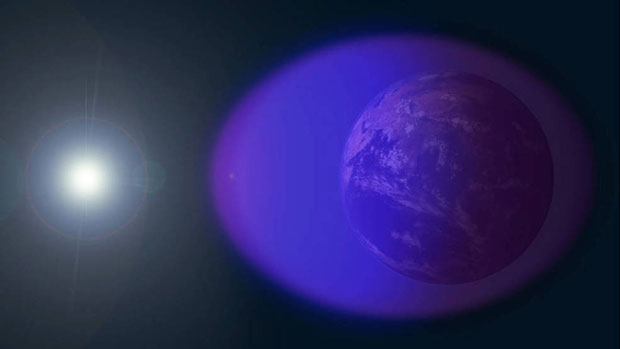
Edge of Tropical Storm Eta seen from NOAA WP-3D Orion N42RF Kermit on Nov. 10, 2020. (Photo: NOAA)
Hurricane season starts June 1. Every year on that date, two Lockheed WP-3D Orion aircraft and a crew from NOAA’s Aircraft Operations Center deploy as “Hurricane Hunters,” flying directly into violent hurricanes to perform aerial weather reconnaissance.
Data gathered helps forecasters make accurate predictions on hurricane strength, direction and threats to land and life. But what is it like to fly these missions? What navigation tools and instruments are used? How do weather conditions impact these flights?
On May 27, the Institute of Navigation will host a webinar presented by Lt. Cmdr. Brian Richards, WP-3D Orion navigator and training section chief for NOAA’s Aircraft Operations Center. Deborah Lawrence, Federal Aviation Administration, will moderate. Space is limited; register early to secure a spot.
“Hurricane Hunters: Navigating a Plane through a Hurricane” Thursday, May 27, at 11:00 a.m. EDT
Esri has released a new mapping app, Air Quality Aware, that fuses data from the EPA’s AirNow program, NOAA’s National Weather Service wind forecast and the American Community Survey to provide location intelligence on current air quality and its impacts on local communities.
At a national level, areas are color-coded according to EPA’s Air Quality Index, with magenta and purple representing hazardous and very unhealthy air quality.
As users zoom in, the map shows the air-quality scores reported at each individual air-quality monitoring station.
Users can click on any station for more information about the pollutants and concentrations reported at that location. They can also search for or click any place on the map to get more information about current and forecasts of air quality, wind speed and insights about the vulnerable population in each place.


![Figure 32: Geoid rate over CONUS based on the GSFC mascon model [mm/yr] (Image: NOAA)](https://stage.globalpositioningnews.com/wp-content/uploads/2022/05/Geoid-rate-CONUS.jpg)
![Figure 33: Geoid rate over Alaska from GSFC mascon model [mm/yr] (Image: NOAA)](https://stage.globalpositioningnews.com/wp-content/uploads/2022/05/geoid-rate-alaska.jpg)