Tag: OEM

  • MEMS oscillators on the move

    Advances in micro-electro-mechanical systems (MEMS) sensor technology include temperature-sensing MEMS oscillators (TSMO). Pairing a TSMO with a GNSS receiver, the authors successfully performed carrier-phase positioning and obtained accuracies better than typically required for automotive applications. MEMS oscillators can present space and cost advantages in integrated circuit assembly.
    By Bernhard M. Aumayer and Mark G. Petovello

    MEMS oscillators have found their way into the electronics industry and are on their way to enter a multi-billion consumer devices market, which is currently dominated by crystal-based oscillators. One technology review concluded that MEMS oscillators fill the gap between high-performance quartz and low-performance LC (inductor+capacitor) oscillators while allowing for better system and package integration.

    Nevertheless, due to stringent requirements on frequency accuracy and phase noise, MEMS oscillators have not yet been integrated in GNSS receivers.

    In earlier research, we demonstrated the feasibility of using a temperature-sensing MEMS oscillator (TSMO) in a software receiver, operated over the full industrial temperature range (–40° to +85° C) for pseudorange (code) positioning. However, high-accuracy carrier-phase positioning techniques require uninterrupted carrier-phase tracking, producing more challenging requirements for the receiver’s oscillator.

    Here, we extend that research to demonstrate the feasibility of using a TSMO for carrier-phase positioning.

    Background

    The MEMS resonator used here has an approximately 150 ppm frequency drift over the temperature range of –40° to +85° C, which is about three to five times greater compared to a standard crystal. The integrated temperature sensor provides very good thermal coupling with the resonator, enabling accurate frequency estimation once the frequency versus temperature function (FT polynomial) is estimated.

    This FT polynomial can be estimated by periodically measuring the frequency and temperature at different temperatures, and fitting the FT polynomial to the measurements. After this calibration stage, the oscillator frequency error can be estimated using the temperature measurement and the polynomial only. This frequency error can aid the GNSS receiver for acquiring and tracking signals.

    As the temperature measurements are affected by noise — which is also amplified by the FT polynomial, producing frequency noise in the receiver — the temperature measurements can be filtered accordingly to reduce noise.

    Methodology

    Temperature compensation of the oscillator frequency can be beneficial in scenarios with fast changes in temperature (and therefore fast changes in frequency) or when operating the oscillator at extreme temperatures, where temperature sensitivity is more pronounced. The TSMO implements an onchip integrated temperature sensor in close proximity to the resonator and provides an accurate estimate of its temperature. We first examine more complex and non-real-time capable filters to assess performance improvement and limits of bandwidth reduction.

    For the second part of this research, where the TSMO based GNSS receiver’s measurements are used for RTK positioning, none of the conditions requiring temperature compensation (fast changes or extreme temperatures) are met, and therefore temperature compensation was not applied.

    Temperature Measurements Filtering. When temperature compensation is applied, filtering of the chip-integrated temperature sensor measurements is performed to reduce measurement noise introduced by the temperature measurement circuit. As the signal frequency and phase from the satellite can — under negligible ionospheric scintillation conditions — be assumed significantly more accurate and stable than the local oscillator’s carrier replica, common errors in the received signals’ carrier frequencies can predominantly be accredited to the local oscillator.

    Therefore, under the condition of a defined tracking loop, estimated frequency accuracy and phase tracking stability are suitable measures of the local oscillator’s short-term frequency and phase stability, as well as the influence of the temperature compensation.

    The temperature compensation method is being digitally applied to the digitized IF signal as a first stage in the software receiver (Figure 1). For generating this signal, a filtered version of the raw temperature measurements is generated and a function (temperature compensation or FT polynomial) to convert those temperature measurements to local oscillator frequency estimates is applied.

    Figure 1. Temperature compensation and signal processing structure. Source: Bernhard M. Aumayer and Mark G. Petovello
    Figure 1. Temperature compensation and signal processing structure.

    The digitized IF samples of the received signal as well as the frequency estimates from the temperature measurements are then processed by the GSNRx software GNSS receiver developed at the University of Calgary. Satellite-specific phase-lock indicators (PLI) as well as the receiver’s clock-drift estimates are extracted and analyzed, and compared to the results from other filter implementations.

    The temperature filters are designed as a combination of variable length finite impulse response (FIR) filters and 1-tap inifinite impulse response (IIR) filters, as this design yields a reasonable trade-off between high stop-band attenuation, small group delay, low complexity and high filter stability. Although feasible in hardware implementations, multi-rate filtering approaches were not investigated.

    The filters used are summarized in Table 1, where filters #1 and #2 were used in our previous research. In the table, BC denotes a box-car FIR filter implementation, and BW refers to an approximated brick-wall filter (truncated sinc in time domain). Although the order of the filter is higher, all feedback coefficients (an) other than the first a1 are zero for stability reasons. The stated bandwidth is the 3 dB bandwidth of the filter, (fwd/bwd) indicates forward and backward filtering, and GDC indicates group delay compensation.

    Table 1. Filter implementations for temperature measurements. Source: Bernhard M. Aumayer and Mark G. Petovello
    Table 1. Filter implementations for temperature measurements.

    Carrier-phase positioning. It is well known that carrier-phase measurements can deliver much higher accuracy positions than pseudorange measurements. The challenge for MEMS oscillators is to mitigate the phase noise of the resonator, and any noise resulting from temperature compensation, to allow continuous phase tracking. Failure to do this will result in more cycle slips, which in turn will limit the benefits of using carrier-phase measurements (since the navigation filter will have to more frequently re-estimate the carrier-phase ambiguities).

    Testing

    The static data set collected in our earlier research was reused for this work. The data was collected from a static rooftop antenna, while the TSMO was placed inside a temperature chamber, which was performing a temperature cycle from +85° to –30° C and back up to +60° C. The temperature compensation polynomial (Figure 1) was fit using the clock drift estimate from running the software receiver with the same data set without any temperature compensation. The temperature filters in Table 1 were then applied to the raw temperature measurements, and processed with the same software receiver as in our earlier work, allowing for direct comparison of the results.

    Carrier-phase positioning. To mitigate effects from orbit and atmospheric errors, first a zero-baseline test was carried out on a rooftop antenna on the CCIT building at the University of Calgary. Two identical IF sampling front-ends with a sampling rate of 10 MHz were used for each of the tests, one utilizing a built-in TCXO and the other using the external MEMS oscillator clock signal. A commercial GNSS receiver was used as a static base for this setup. The TSMO and TCXO based front-ends were used as a rover, all connected to the same antenna. For all tests, only GPS L1 C/A signals were used by the devices under test.

    Second, a short-baseline test utilizing two antennas about 2.5 m apart was carried out, with the same equipment. For reference, surveyed coordinates of the antennas’ base mounts were used. For these two tests, the front-ends and oscillators were at constant temperature (to within variation of room temperature) on a desk.

    Third, two road tests in a car driving around Springbank airport close to Calgary were performed. One test involved smooth driving only, and the second test was performed by rough driving over uneven roads so that higher accelerations on the oscillators were provoked. To allow a performance comparison between the TCXO and TSMO based receivers, the two front-ends were used as rover receivers at the same time and were connected to the same geodetic-grade antenna mounted on the vehicle’s roof.

    Equipment and processing. All samples from the IF-sampling front-ends were processed with the University of Calgary’s GSNRx software GNSS receiver to obtain code and carrier phase as well as Doppler measurements. These measurements were subsequently processed with the University of Calgary’s PLANSoft GNSS differential real-time kinematic (RTK) software to obtain a carrier-phase navigation solution.

    As a reference, a commercial GNSS/INS system using a tactical-grade IMU was used. The dual-frequency, multi-GNSS, carrier-phase post-processing of the reference data provided a reference position of better than 1 cm estimated standard deviation in all three axes, which is in the following referred to as “truth.”

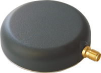
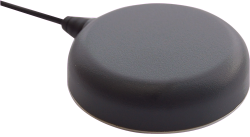
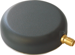
    The kinematic tests were carried out with the PLAN group’s test vehicle, a GMC Acadia SUV-style vehicle. A geodetic-grade antenna was mounted in close vicinity to the LCI tactical-grade IMU as shown in Figure 2. The antenna was split to a reference receiver and the two IF-sampling front-ends. The front-ends were rigidly mounted to each other as well as to the TSMO board to ensure similar accelerations on both oscillators. The front-ends were placed in the center of the passenger cabin.

    Figure 2. Equipment setup on PLAN group’s test vehicle. Source: Bernhard M. Aumayer and Mark G. Petovello
    Figure 2. Equipment setup on PLAN group’s test vehicle.

    The kinematic tests were performed near the Springbank airport close to Calgary, Alberta. For a base station, a commercial dual-frequency receiver was set up on an Alberta Survey Control Marker with surveyed coordinates. A leveled antenna was used with this receiver, and 20 Hz GPS and GLONASS raw measurements were collected to provide a base for both the reference receiver and the receivers under test.

    Results

    First, we compared results from improved temperature filtering to results from our earlier work. The performance of temperature measurement filtering is quantified with regard to frequency accuracy (mainly arising from filter group delay) and phase-lock indicator values of the tracked signals, which are mainly deteriorated from noise introduced by temperature compensation.

    The best performance with regard to PLI (Figure 3) was achieved using the forward-backward 1-tap IIR filter (#4 in Table 1).

    Figure 3. Cumulative histogram of PLI with temperature compensation. Source: Bernhard M. Aumayer and Mark G. Petovello
    Figure 3. Cumulative histogram of PLI with temperature compensation.

    While the estimation error introduced by this low-bandwidth and high group delay filter was significant especially at fast temperature changes before and after the temperature turnaround point at 2067 s into the run (Figures 4 and 5), the forward-backward filtering cancels a major part of that delay. Note that this filter has even lower bandwidth (Table 1) than the same filter used in forward-only filtering, as the resulting magnitude response squares with the forward-backward filtering approach.

    Figure 4. Temperature-based estimation of oscillator error. Source: Bernhard M. Aumayer and Mark G. Petovello
    Figure 4. Temperature-based estimation of oscillator error.
    Figure 5. Error in temperature-based estimation of oscillator error (note the larger error due to filter delay). Source: Bernhard M. Aumayer and Mark G. Petovello
    Figure 5. Error in temperature-based estimation of oscillator error (note the larger error due to filter delay).

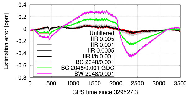
    Only a slight performance decrease can be seen when using a boxcar filter with 2048 taps, but only when compensating for the FIR part’s known group delay of approximately 1 s. It is noted that filters #4 and #6 — which show best performance — are only usable in post-processing or with significant latency.

    In contrast to group-delay compensated filters, which might not be applicable in low-latency, real-time applications, the even lower bandwidth 1-tap IIR filter — although introducing a still significant group delay — resulted in best tracking performance amongst the filters, which are not compensated for any group delay. This filter’s performance is surprisingly followed by the low-complexity 1-tap IIR filter (#3) ahead of the filters implementing the boxcar (#5) or brickwall (#7) filter blocks. The reasoning for this lower performance — given the results of the equal coefficients but group delay compensated filter (#6) performance — can be found in the higher delay of the measurements compared to the group delay compensated filter. The difference between boxcar and brickwall filter was found to be negligible with this data set.

    In general, the receiver was able to provide very good carrier-phase tracking using all of the proposed filters. The satellite signals were tracked with a PLI of better than 0.86 between 98 to 99.8 percent of the time, depending on the implemented filter; this corresponds to approximately 30 degrees phase error or 2 cm ranging error at the L1 frequency.

    Short baseline test. Both receivers correctly fixed the ambiguities within 150 s, kept the ambiguities fixed until the end of the data set, and computed the correct position with an estimated accuracy of better than 1 cm in each axis. The position estimate error is comparable between the two receivers, and slightly higher than in the zero-baseline test because multipath errors are no longer removed. Figure 6 shows the position estimates errors for both receivers. No significant systematic errors are evident in the position errors from these tests. The slowly varying error in height is typical for multipath signals.

    Figure 6. Short baseline position estimates error for TSMO (top) and TCXO (bottom) based receivers. The color bar at the bottom denotes the ambiguity status: all fixed ambiguities (green), partially fixed ambiguities (yellow) and float-only ambiguities (red). Source: Bernhard M. Aumayer and Mark G. Petovello
    Figure 6. Short baseline position estimates error for TSMO (top) and TCXO (bottom) based receivers. The color bar at the bottom denotes the ambiguity status: all fixed ambiguities (green), partially fixed ambiguities (yellow) and float-only ambiguities (red).

    The double-differenced phase residuals are slightly higher for both receivers than in the zero-baseline test (not shown), but follow the same trend for both receivers and are therefore accredited to the signals or processing software rather than to the oscillator.

    The phase-lock indicator values for all satellites are visualized in a cumulative histogram in Figure 7. Because the TSMO based receiver’s PLI values are on average slightly smaller than for the TCXO based receiver, higher noise is expected in those measurements. Nevertheless, in the processed data sets, this has no significant effect on the estimated position.

    Figure 7. Cumulative histogram of PLI values for TSMO and TCXO-based receivers in short baseline test. Source: Bernhard M. Aumayer and Mark G. Petovello
    Figure 7. Cumulative histogram of PLI values for TSMO and TCXO-based receivers in short baseline test.

    Kinematic Tests

    The first test was performed on paved rural roads. Any road unevenness was avoided where possible, or driven over fairly slowly where unavoidable. The test started with an approximate 150 s static time to assure initial fixing of the ambiguities, and continued with driving in open-sky and occasional foliage environment.

    As visualized in Figure 8, both receivers were able to fix the ambiguities correctly within roughly 30 s. During the test, both receivers fell back to partially fixed or float ambiguities. The TCXO based receiver computes a partially fixed solution between 650 s and 1200 s, as apparent from the position errors in Figure 8. In the same interval, the TSMO based receiver computes a float-only solution.

    Figure 8. Smooth driving road test position estimates error for TSMO (top) and TCXO (bottom) based receivers. Source: Bernhard M. Aumayer and Mark G. Petovello
    Figure 8. Smooth driving road test position estimates error for TSMO (top) and TCXO (bottom) based receivers.

    Bumpy Driving. The second test route was chosen to include several locations of road unevenness and a slightly elevated bridge (bump) over a small stream, which was driven over at five different speeds, ranging from approximately 20 to 74 km/h.

    Both receivers were able to compute a sub-meter accurate position during the entire test. While the TCXO based receiver was able to compute a fixed ambiguity position with centimeter-level accuracy during the majority of the test, the TSMO based receiver was able to fix the ambiguities at significantly fewer epochs and reverted to a float ambiguity most of the time, decreasing positioning accuracy to the decimeter-level. From Figures 9 and 10 the times of higher acceleration (>5 m/s) when driving over the bridge (between 260 and 490 s into the test) correlate well with the times of reduced number of fixed ambiguities, and therefore times where the navigation engine is reverting to a float ambiguity carrier-phase solution.

    Figure 9. Bumpy driving road test position estimates error for TSMO (top) and TCXO (bottom) based receivers. Source: Bernhard M. Aumayer and Mark G. Petovello
    Figure 9. Bumpy driving road test position estimates error for TSMO (top) and TCXO (bottom) based receivers.
    Figure 10. Bumpy driving road test number of total and used satellites, and vehicle excess (>5 m/s) accelerations for TCXO based receiver. Source: Bernhard M. Aumayer and Mark G. Petovello
    Figure 10. Bumpy driving road test number of total and used satellites, and vehicle excess (>5 m/s) accelerations for TCXO based receiver.

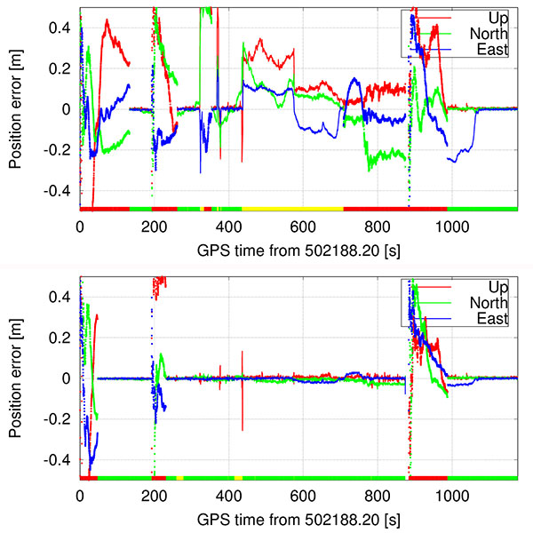
    At approximately 562 s into the test, the vehicle hit a larger puddle on the dirt road resulting in high vertical acceleration (> 1g). Despite this high acceleration, the TCXO based receiver stayed in fixed ambiguity resolution mode, and the TSMO based receiver continued in partially fixed ambiguity solution mode.

    At 875 s into the test, the car passed underneath two separated two-lane highway bridges, which led to a loss of all signals on all receivers, including the reference receiver. Both receivers reacquired the signals after the underpass and fixed the ambiguities again after approximately 100 s.

    Conclusion

    Temperature-measurement filter implementations were presented that outperform the previous low-complexity implementations, but at the cost of higher computational requirements, more latency or even real-time capability because of the more complex design or non-causal filtering approach. Using the proposed filtering approach, the eight strongest satellites were tracked in phase-lock tracking state for 98–99.8 percent of the test time, while performing a full hot-cold temperature cycle.

    Furthermore, we showed the performance of traditional double-differenced carrier-phase positioning using a receiver with a temperature-sensing MEMS oscillator. Static and kinematic tests were performed, and the operation of an otherwise identical TCXO based receiver at the same time allowed to compare the oscillator’s performance in several environments as well as their sensitivity to accelerations. Carrier-phase positioning with TSMO based GNSS receivers was possible with accuracies better than typically required for automotive applications.

    Manufacturers

    The temperature-sensing MEMS oscillator was produced by Sand 9, which has been acquired by Analog Devices, Inc. A NovAtel 701GG geodetic-grade antenna was mounted on the test vehicle and a NovAtel SPAN-SE was the reference receiver. A NovAtel ProPak-V3 was the base station, with a Trimble Zephyr antenna.


    Bernhard M. Aumayer is a Ph.D. candidate in the Position, Location and Navigation (PLAN) Group in the Department of Geomatics Engineering at the University of Calgary. He worked for several years as a software design engineer in GNSS related R&D at u-blox AG.

    Mark Petovello is a professor in the PLAN Group, University of Calgary. His current research focuses on software-based GNSS receiver development and integration of GNSS with a variety of other sensors.

    This article is based on a technical paper presented at the 2015 ION-GNSS+ conference in Tampa, Florida.

  • Marvell’s NFC controller enables tiny antennas for mobile, IoT, wearables

    Marvell, a connectivity and semiconductor company, has launched its Near Field Communication (NFC) 88NF100 Controller with Active Load Modulation (ALM) to support the smallest antenna sizes critical to mobile, IoT, wearable and automotive applications.

    Adhering to the NFC Controller Interface (NCI) Technical Specification version 1.1, the 88NF100 provides an extended operating range and is extremely energy-efficient to enable extended battery life for power critical applications.

    The 88NF100’s ALM technology supports the smallest antenna sizes to enable OEMs to implement NFC capabilities into small form factor designs, such as for mobile, the Internet of Things (IoT), wearable and automotive applications. The controller has extremely low power operation in polling mode to provide increased battery life for power critical applications and three single-wire protocol (SWP) interfaces to secure element (eSE) devices, for for secure payments.

    The patented two-pin antenna interface supports a maximum distance of two meters between the chip and antenna, supporting devices where the antenna must be located far away from the chip, such as with automotive and printer applications, in addition to designs with tight space constraints, including smartphones and wearable devices.

    Seamlessly integrating with Marvell’s Wi-Fi, Bluetooth and ZigBee solutions, the 88NF100 is compliant with the NCI Technical Specification version 1.1 to leverage existing middleware and applications and supports GSMA, ISO and EMVCo industry standards.

    “As consumers demand smarter and more connected devices every year, manufacturers are increasingly faced with the challenge of incorporating advanced technology features into elegant and small form-factor designs. Marvell’s 88NF100 controller with ALM technology is designed to enable OEMs to incorporate advanced NFC technology into compact and energy-efficient designs with ultra-small antennas,” said Kevin Tang, senior director of marketing, Wireless Connectivity Business Unit at Marvell. “Marvell’s wireless technology enables the ultimate performance, battery life and operating range, making the 88NF100 ideal for NFC applications in Mobile payments, point of sale (POS) systems, Smart home connected devices, Smart watches and vehicles.”

    Key features of the Marvell 88NF100 include:

    • Low-power consumption.­ The 88NF100 supports all data rates up to 848 kbps and operates with a low polling current of 60uA, making it ideally suited for power critical applications.
    • ALM integration.­ The controller’s ALM technology supports smaller antennas; and allows placement of the antenna up to two meters from the 88NF100.
    • Advanced digital processing for reader mode. The 88NF100’s signal processing has been optimized for better performance, enabling better reading distance in peer-to-peer (P2P) modes.
    • Advanced low-battery operating mode. The controller can operate on a very low current from the battery, ensuring that mobile applications deliver the same performance level in card emulation (CE) mode when the phone is powered on or off.
    • Compact package with low pin count.­ The 88NF100 has embedded wafer level ball grid array (eWLB) 2.5 x 2.5 and a compact 4 x 4 quad-flat no-leads (QFN) package.
    • Local Interconnect Network (LIN) interface.  The LIN interface is designed to enable developers to build low cost NFC LIN nodes for the automotive industry and natively support the automotive LIN communication protocol.
  • u‑blox 8 provides GPS/GLONASS receiver platform for low-power devices


    u-blox has released the u‑blox 8 GPS/GLONASS receiver platform. It complements the u-blox GNSS platform portfolio by addressing power sensitive usage, whereas the existing u-blox M8 platform continues to serve applications where navigation performance and highest accuracy are paramount.

    u-blox 8 offers significant improvements, compared with its predecessor u-blox 7. The tracking sensitivity has been increased by 4 dBm, and is now -166 dBm.

    The enhanced odometer functionality, a new geofencing feature, and optimized preset power save modes can halve the power requirements for sport products. Free-of-charge AssistNow for boosting GNSS acquisition performance, which is available online, offline or as an autonomous service, has been improved. It also makes the new positioning platform ideal for all battery powered devices, especially wearables and sports tracking.

    “Nowadays many portable applications rely on a single coin battery; hence low power-spending is crucial,” said Uffe Pless, Product Marketing and Positioning, u‑blox. “u‑blox 8 has been developed for wearables and tracking applications, keeping in mind the need for low power consumption without compromising performance.”

    u‑blox 8 is pin-compatible with u‑blox 7. It will be available as a chip and as modules in several form factors. Customer samples of u‑blox 8 chips and modules will be available by Q2 2016.

  • Broadcom announces automotive global navigation chip at CES 2016

    Broadcom Corporation has added a new GNSS wireless connectivity chip to its automotive portfolio, which it unveiled at CES 2016, being held this week in Las Vegas.

    Automotive GPS shipments are expected to more than double by 2022, creating significant opportunities among component suppliers and increasing competition for market share. The chip offers wideband capture radio technology for simultaneous tri-band reception of all visible GNSS satellites including GPS, Galileo, QZSS, GLONASS, BeiDou and global SBAS augmentation systems.

    Broadcom’s BCM89774 provides improved location and positioning while lowering power consumption for in-vehicle applications and reduces bill of materials cost for car makers, by integrating the sensor hub and CPU on a single chip.

    The BCM89774 delivers original equipment manufacturers (OEMs) one of the most accurate solutions available today, Broadcom said. The new chip also improves positioning in dense urban environments and foliage-blocked areas to enhance the consumer experience.

    Optimized to meet the rigorous standards of the automotive industry, the BCM89774 has been tested to AECQ100 automotive environmental stress requirements, is manufactured in TS16949 certified facilities, and offers full production part approval process (PPAP) support.

    “Broadcom’s new GNSS connectivity chip for automotive keeps car makers and tier one suppliers ahead of the curve with advanced precision and reduced power consumption while lowering BOM cost,” said Richard Barrett, Broadcom Director of Automotive Wireless Connectivity. “By delivering premium products that meet automotive grade requirements, we are positioned for growth in this accelerating market.”

    Key Features:

    • Low-power mode for emergency service and theft tracking applications
    • Location awareness capabilities added to traditional functions of a sensor hub for lower power consumption and BOM costs
    • Simultaneous reception of GPS, GLONASS, BDS, QZSS and Galileo navigation satellites
    • Support for global Satellite Based Augmentation System (SBAS) system
    • Management of CAN BUS inputs and sensors such as accelerometers, gyroscopes, and magnetometers to provide a fused sensor data tracking subsystem
    • Best-in-class acquisition, tracking sensitivity and time-to-first-fix in both cold and hot starts
    • Full pass through capability for external host-based systems
    • Tested to AECQ100 automotive environmental stress requirements and manufactured in TS16949 certified facilities
    • Full production part approval process (PPAP) support

    Availability
The BCM89774 is currently sampling.

  • CES 2016: Qualcomm unveils processor for connected cars

    Snapdragon-QualcommQualcomm Technologies has introduced its latest Qualcomm Snapdragon automotive processors, the Snapdragon 820 Automotive family, offering a scalable next-generation infotainment, graphics and multimedia platform with machine intelligence and a version with integrated LTE (long-term evolution)-Advanced connectivity.

    The Snapdragon 820A is Qualcomm Technologies’ newest automotive-grade system-on-chip (SoC). Qualcomm Technologies has taken a modular approach to designing the Snapdragon 820A, enabling a vehicle’s infotainment system to be upgradable through both hardware and software updates, thereby enabling vehicles to be easily upgraded with the latest technology.

    The Snapdragon 820A’s sensor integration provides cognitive awareness and vehicle self-diagnostics, supports ADAS features for improved vehicle safety systems, and provides location and navigation through GNSS and dead-reckoning technologies.

    Qualcomm Technologies is demonstrating the upgradeable module at the Qualcomm Automotive booth, North Hall #915, at CES 2016, being held in Las Vegas this week.

    The Snapdragon 820A family is based on 14-nm FinFET advanced process node running Qualcomm Technologies’ custom 64-bit Qualcomm Kryo CPU, Qualcomm Adreno 530 GPU, Qualcomm Hexagon 680 DSP with Hexagon Vector eXtension (HVX), Qualcomm Zeroth machine intelligence platform, and the Snapdragon 820Am version with integrated X12 LTE modem capable of 600 Mbps downlink/150 Mbps uplink. The 820A is engineered with custom-built, highly optimized cores designed for heterogeneous computing — the ability to combine its diverse processing engines within the SoC, such as the CPU, GPU and DSP cores, to achieve previously unattainable performance and power savings.

    The Zeroth initiative, a machine intelligence platform on Snapdragon 820A, is designed to enable automakers to develop state-of-the-art deep learning-based solutions using neural networks for advanced driver assistance systems (ADAS) and in-vehicle infotainment scenarios, and run them efficiently on embedded platforms in the vehicle. Zeroth accelerates execution of deep neural networks using the heterogeneous compute engines that are part of the Snapdragon 820A. A Zeroth-powered development kit for automotive solutions will be available for the Snapdragon 820A.

    “With the Snapdragon 820 Automotive processing platform, we are delivering an unprecedented level of performance and technology integration designed to significantly enhance the consumer’s safety and in-vehicle experience. Never before has the unparalleled combination of integrated LTE cloud connectivity, powerful heterogeneous computing, leading-edge multimedia performance and breakthrough machine learning capabilities been delivered in a single chip, fully integrated, automotive grade solution,” said Patrick Little, senior vice president and general manager, automotive, Qualcomm Technologies.

    “The automotive industry has long been asking for a single scalable solution capable of delivering the rich user experience and level of performance, connectivity and upgradability that consumers are accustomed to on their personal mobile devices,” Little said, “including real-time cloud connectivity and navigation, immersive 4K graphics and video displays, the flexibility of hardware and software upgradability, and the deep learning and remote diagnostic capabilities needed to deliver the next level of safety performance in the vehicle. The Snapdragon 820 Automotive platform has been designed to deliver all of these capabilities and much more.”

    The version with integrated X12 LTE modem is designed to support continuous in-car and cellular connectivity, featuring the leading 4G LTE Advanced Pro that can support up to 600 Mbps download/150Mbps upload speeds, stream HD movies into the car, serve as a Wi-Fi hotspot supporting 802.11ac 2×2 MIMO, connect multiple mobile devices inside the car, and support 802.11p DSRC for V2X (vehicle to vehicle/infrastructure/pedestrian) communications. Local connectivity inside the car via Bluetooth supports content sharing between mobile devices brought into the car and the car’s infotainment system.

    Qualcomm Technologies is also helping to lead the 3GPP in developing specifications for automotive V2X, for both LTE release 14 (LTE V2X) and 5G standards.

    “Like Qualcomm Technologies, AT&T is committed to the connected car and takes a similar approach to technology development with the AT&T Drive platform, offering a global, modular solution to automakers to enable best-in-class user experiences for their drivers,” said Chris Penrose, senior vice president, Internet of Things, AT&T Mobility. “We design our solutions to provide better connectivity, flexibility and upgradability on our network, and Qualcomm Technologies’ development of the Snapdragon 820A Smart LTE Module is a prime example of this same approach to technology.”

    By integrating advanced camera and sensor processing, the 820A supports critical always-on warnings and emergency services, extends standard cameras to Intelligent Cameras, and supports parking assist periphery vision features using surround view cameras. These features are supported by the on-chip Hexagon 680 DSP with HVX, which supports multiple automotive camera sensors connected simultaneously.

    The Snapdragon 820A family of automotive-grade processors is designed for the automotive ecosystem and offers these features:

    • Scalable and modular platform offering pin, package and software-compatibility, with optional integrated LTE capability that is hardware and software upgradeable as wireless network technology evolves.
    • Supports vertical tiering options by offering the Snapdragon 820A family across premium to standard performance configurations.
    • Comprehensive software support for QNX, Linux and Android, as well as substantial platform-level integration of high value sub-systems to respond to the acceleration in refresh cycles while managing cost.
    • The connectivity, multimedia and graphics capabilities allow many real-time cloud based features, including streaming multimedia, enterprise collaboration, real-time maps and location services, remote diagnostics and one-touch telematics, with substantial potential for performance, connectivity and multimedia innovation for auto OEMs.
    • The upgradability option allows a wireless operator to offer an 820A Smart LTE Module concept for the version with an integrated modem that allows cellular connectivity to be updated through both hardware and software when new features become available on the cellular network.

    Qualcomm Technologies is also collaborating with Aisin AW to develop the modular infotainment solution utilizing the Snapdragon 820A. “We expect the 820’s powerful features will deliver superior processing power, graphics performance and low power consumption demanded by next generation infotainment systems,” said Kyomi Morimoto, managing officer, Aisin AW.

    Automotive samples of the 820A family are expected to be available in the first quarter of 2016. A number of concept vehicles and demonstrations based on the Snapdragon 820A, from Qualcomm Technologies and other automotive industry leaders, will be shown in the Qualcomm Automotive booth, North Hall #915 at CES 2016.

  • CES 2016: Bosch Sensortec unveils intelligent accelerometers and high-performance gyroscopes

    Bosch Sensortec is unveiling new generations of intelligent accelerometers and high-performance gyroscopes at the 2016 International CES in Las Vegas.

    Aimed at smartphones, tablets and wearables, the new devices cover a wide range of requirements, from low-power consumption for always-on applications such as step counting, to high-performance optical image stabilization (OIS).

    Intelligent three-axis accelerometers — BMA422 and BMA455

    Today’s applications running on modern mobile devices place many demands on motion sensors. These sensors are required to continuously sense motion, such as for step counting operations, while at the same time delivering a high level of performance without compromising battery lifetime.

    To meet these challenges, the new sensors from Bosch Sensortec integrate embedded intelligence functionality into standalone accelerometers. Adding intelligent features to an accelerometer enables innovative applications, while minimizing power consumption by eliminating the need to wake up an application processor or an additional discrete sensor hub. Overall system power management and user experience can be improved by the accelerometer detecting and processing motions such as glance, pick-up and tilt.

    Current consumption of the new accelerometers is kept very low to extend battery life. The integrated Android 6.0 “Marshmallow” features minimize programming effort for customers. Each device delivers outstanding accelerometer performance for low offset, low temperature coefficient offset (TCO) and low noise levels, the company said.

    Two new accelerometers are being launched: the BMA422 “all-rounder” is suitable for standard applications, and the BMA455 provides high performance for gaming and immersive activity tracking. In addition, the high level of performance enables demanding applications covering augmented reality, virtual reality, image stabilization and industrial measurement applications such as spirit leveling and inclination measurement.

    High-performance gyroscopes — BMG250 and BMG280

    Mobile devices require gyroscopes for many applications, including gaming, augmented reality, virtual reality and OIS. To provide the necessary performance, Bosch Sensortec’s new gyroscopes combine the most important parameters in a single device: low noise, low TCO and high bias stability.

    Although delivering high performance, they do both feature the lowest power consumption of any standalone gyroscope in the market, thus helping to extend battery lifetime in mobile devices.

    Today’s announcement includes two three-axis gyroscopes: the BMG250 provides low noise, low TCO and high bias stability, while the BMG280 delivers ultra-low noise optimized for OIS and includes a secondary interface for OIS, making it fit for use in camera modules. The BMG280’s secondary interface can be used in parallel with the primary user application interface, for example for simultaneous panorama creation and OIS.

    Packages and availability

    The new devices are provided in small packages. The BMA422 measures 2.0 x 2.0 x 0.95 mm³, while the BMA455 is 2.0 x 2.0 x 0.65 mm³. The BMG250 and BMG280 gyroscopes both measure 3.0 x 2.5 x 0.83 mm³.

    Samples of the all sensors are available now, with mass production of the gyroscopes to commence in Q1 2016 and mass production of the accelerometers starting in mid-2016. For pricing, contact Bosch Sensortec.

  • P3 predicts connected car focus of upcoming automotive, tech shows

    Automotive and consumer technology teams in Detroit and Silicon Valley remain hard at work preparing to kick-off the New Year with new technology at two of the nation’s biggest showcases of automotive connectivity: CES 2016, held Jan. 6–9 in Las Vegas, and the North American International Auto Show, held Jan. 11–24 in Detroit.

    Samit Ghosh, Ph.D., president and CEO of P3 North America, has worked with U.S. automakers on connected vehicle technology since 2005. He shared his thoughts on the future of driving and what to expect at the upcoming shows in a news release from the company.

    “Autonomous driving, information and entertainment systems will continue to take center stage in 2016 as automakers focus on chips, sensors and smartphone applications as key consumer differentiators,” Ghosh said. “In-car entertainment and safety capabilities provided through telematics and infotainment technologies are rapidly becoming the reasons consumers buy vehicles, so the stakes have never been higher.”

    Underscoring the growing intersection of consumer technology and the car, Ghosh pointed to CES reports that its automotive exhibit space will grow 25 percent at the 2016 show, with nine auto makers and 115 automotive tech companies debuting products.

    “Complex technologies require efficient processes,” Ghosh said. “The connected car ecosystem is complicated and faces many challenges, but automakers are beginning to think differently about the way they incorporate technology into cars. They need to start by rethinking their organizations and processes, breaking down organizational silos and taking an end-to-end view of all the touch points that spell success in the rapidly changing IoT ecosystem.

    “Hot topics at this year’s auto shows will be the security of connected vehicle systems and the safety implications of evolving driver interfaces. Automakers also face the tough decision to remain proprietary or join the open source software movement, as smartphones become universal devices for controlling every consumer’s world. From personalized in-car entertainment to smart home integration, the car is becoming a critical link in our interconnected world,” he said.

    According to Ghosh, in the software-focused world, carmakers can achieve far greater economies of scale by sharing technology with all other automakers. He cited GENIVI open source In-Vehicle Infotainment software as one force working to shorten development cycles and reduce OEM costs.

    “As an independent systems integrator, P3 efficiently connects and unites large industry players to quickly and successfully innovate,” Ghosh said. “The way we manage projects and optimize our clients processes is extremely unique. Our international experience in both the automotive and the telecommunications industries gives us the exact perspective needed to help these converging industries accelerate the development of connected car technology.”

  • Skyworks launches GNSS front-end modules with integrated filters

    Skyworks Solutions, which manufactures analog and mixed-signal semiconductors, has launched three low-noise amplifier (LNA) front-end modules with integrated filters for GNSS. The devices are designed to provide high linearity, excellent gain, a high 1-dB input compression point and a superior noise figure.

    The pre-filters provide the low in-band insertion loss and integrated notch filtering for excellent rejection of desired frequency bands.

    Each device is supplied in small-footprint, surface-mount technology multi-chip module packaging — 1.1 x 1.5 x 0.7 millimeters for the SKY65713-11, and 1.7 x 2.3 x 0.7 millimeters for the SKY65715-81.

    The SKY65713-11 and SKY65715-81 both support products integrating GNSS functionality such as smartphones, personal navigation devices, wearables, machine-to-machine (M2M) systems, base stations, asset tracking instruments, professional radios and Internet of Things (IoT) applications. Both are designed for BeiDou and GPS receiver applications.

  • Septentrio introduces next-generation GNSS reference receiver — PolaRx5

    Septentrio introduces next-generation GNSS reference receiver — PolaRx5

    Image_PolaRx5_above_cleaned_sharp_smaller.163016Septentrio has launched its next-generation GNSS receiver for precise scientific and geodetic applications — the PolaRx5. This new receiver in the PolaRx product line is developed specifically to support the most demanding applications for the Earth science community offering a select range of advanced features that enable maximum accuracy and functionality.

    Powered by Septentrio’s next generation multi-frequency engine, the PolaRx5 offers 544 hardware channels for robust and high-quality GNSS tracking. The receiver supports all major satellite signals including GPS, GLONASS, Galileo and BeiDou, as well as regional satellite systems including QZSS and IRSS.

    Septentrio’s Advanced Interference Mitigation (AIM+) technology enables the PolaRx5 to filter out both intentional and unintentional sources of radio interference, from narrowband signals over high-powered pulsed signals to chirp jammers and Irridium interferers. Furthermore, Septentrio’s patented APME+ multipath mitigation technology — which eliminates short delay multipath without introduction of bias — guarantees superior measurement quality. If needed, the user has the ability to activate or deactivate APME+ to obtain completely unmodified measurements.

    Various independent tests have shown PolaRx5 consistently ranks high among GNSS receivers in many areas of measurement quality, including fewest number of cycle slips and lowest power consumption well below 2W.

    PolaRx5 also introduces a new standard in ease-of-use. Thanks to Septentrio’s comprehensive web interface and the built-in Wi-Fi and Bluetooth interface, users have complete control and visibility of the receiver. The user’s web browser provides secure access to all receiver settings and status, data storage and firmware upgrades, as well as advanced monitoring such as a built-in spectrum analyzer.

    “With PolaRx5, Septentrio has developed an advanced GNSS reference receiver to meet the advanced needs of our customers,” said Jan Leyssens, PolaRx5 product manager. “The selection of PolaRx by UNAVCO for their reference receiver needs illustrates the strengths of Septentrio’s robust technology and PolaRx’s innovative features such as its interference robustness, spectrum analyzer and web interface to make the PolaRx5 the leading GNSS reference receiver on the market today.”

  • Launchpad: New receiver module, UAV developments

    Launchpad: New receiver module, UAV developments

    OEM

    The K528G GNSS board.
    The K528G GNSS board.

    GNSS OEM board

    Positioning and heading for mission-critical applications

    The K528G dual-frequency, multi-constellation GNSS board provides the highest accuracy in differential positioning. It benefits from numerous constellation signals because of its advanced tracking performance of both GPS and GLONASS. The K528G can provide positioning and heading information generated by two antennas. It is designed for guiding and positioning construction engines, dredges, barges, shipping container cranes, mining equipment and intelligent transportation systems.

    ComNav Technology, 
www.comnavtech.com


    GPS/GNSS splitters

    GPS/GNSS splitters

    Designed for small-cell and distributed antenna systems

    GPS Source has released of a line of GPS/GNSS splitters created for the small-cell wireless and distributed antenna system markets. Specifically designed for the L-band frequency, they can eliminate the cost of multiple antennas and long cable runs in wireless installations. With four or eight outputs, the new line of splitters make it possible to use a single GPS referencing antenna and cable arrangement for multiple synchronized systems. The splitters include features such as DC bias select and amplification. GPS Source RF signal splitters typically operate in conjunction with an active GPS antenna; consequently, a GPS RF signal splitter must have provisions for managing the DC voltage to the active GPS antenna. The S14GT and S18GT splitters will power an external GPS antenna from any of the RF outputs. A “hunt-and-pick” circuit is used to select only one DC input for power should more than one source be connected. Designed for redundancy, if the selected DC bias input should fail, the DC bias will automatically switch to another DC input to ensure an uninterrupted power supply to the active antenna.

    GPS Source, www.gpssource.com


    Tallysman-TW2XOX-antenna

    Wideband Antennas

    For precision industrial, agricultural and military OEM applications

    A new series of L1 band wideband antennas for OEM applications is offered in three formats:
    ▪ TW2106/TW2108 — GPS L1
    ▪ TW2406/TW2408 — GPS + GLONASS
    ▪ TW2706/TW2708 — Galileo, BeiDou, GPS + GLONASS
    Each antenna type features Tallysman’s Accutenna technology, which provides high rejection of multipath signals, with low axial ratios and tight phase center variations (PCV). Each is available with a brickwall pre-filter option to protect against saturation by high level subharmonic and L-band signals. The antenna printed circuit boards (PCBs) are 56 millimeters in diameter with four plated holes for secure mounting. They are available with a variety of connectors and custom cable lengths, and can be custom-tuned. All of them are REACH and ROHS compliant.

    Tallysman, www.tallysman.com


    NVS_Tech_NV08C-CSM-W

    L1 RTK receiver

    Heading guidance 
for precision applications

    The NV08C-RTK-A is fully integrated multi-constellation L1 heading receiver with embedded real-tiime kinematic (RTK) functionality and compatibility with GPS, GLONASS, Galileo and BeiDou. The NV08C-RTK-A is designed for use in high-accuracy applications that demand low-cost, low-power consumption, a small form factor and high performance, such as construction, mining and industrial; environmental and structural monitoring; machine control; parallel driving systems; precision agriculture; UAVs; and robotics and intelligent machines.

    NVS Technologies, www.nvs-gnss.com


     Survey

    Satlab_SLD_100-O

    Hydrographic rover accessory

    Hydrographic Echo Sounder designed for GNSS rover

    The SLD-100 GNSS Rover accessory facilitates hydrographic measurement in bodies of water up to 100 meters in depth. it is designed for anyone who finds themselves needing to survey into bodies of water, streams and rivers. With survey-grade accuracy, the SLD-100 can be added to any brand GNSS RTK rover to allow for position and depth measurements to be made simultaneously. With a built-in 10-hour lithium battery and transmitter unit with Bluetooth connectivity, the SLD-100 provides standard-depth data streams in several industry-standard NMEA formats at 1 Hz, 4800 bps, providing compatibility with any hydrographic surveying software package. Position and depth information is externally logged on a computer or controller. Included transom mounting hardware enables easy installation.

    Satlab Geosolutions, www.satlabgps.com


    TriAnt-W

    Rugged GNSS antenna

    Provides protection 
in harsh environments

    TriAnt is small, thin and rugged high-performance GNSS antenna. It measures 128 x 128 millimeters (mm) square and 39 mm thick. It can be mounted with three screws to flat surfaces. It is designed for applications such as machine control and surround anennas of the TRIUMPH-4X. The antenna cable is routed through the center of the antenna (TNC connector) for protection in harsh environments. The TriAnt can also be mounted on poles (1–14 inches thread) using its mount-pole attachment, which increases the thickness to 54.5 mm.

    JAVAD GNSS, www.javad.com


    CHC-NAV-X20i_2-W

    iOS-ready L1 receiver

    Turns iPad or iphone 
into mobile mapper

    The X20i L1 GPS receiver by CHC Navigation is powered by a high-precision L1 GPS engine. Its integrated Bluetooth chip enables it to wirelessly collect submeter positions in real- time or centimeter post-processed on an iPhone or iPad. All location-aware apps on the iPhone and iPad are compatible with the X20i. Immediately after pairing and answering the security question allowing the X20i to take control of location services on the iOS device, 1 million iOS applications are capable of utilizing the high-accuracy data of the X20i, and become accurate to either 1 foot or 1 centimeter. Apps that can make use of the high accuracy include TerraGo Edge, ESRI’s ArcView Connector and those by CarteGraph Systems.

    CHC Navigation, www.chcnav.com


    Mapping

    BlueStar_receiver-W

    Mapping with Bluetooth

    Sub-meter precision 
for android devices

    BlueStarGPS offers both GPS and GNSS options in a rugged, lightweight package. The BlueStarGPS device was designed to meet sub-meter mapping and data-collection needs in the pipeline and utility industries. It provides sub-meter precision without post-processing, and maintains accurate positioning when the SBAS signal is obstructed. This means it can function under trees, around buildings and in rugged terrain where other receivers can fail. The BlueStarGPS is designed specifically for use with Android mobile devices, such as smartphones, tablets or notebook computers, as well as cable and pipe “locating” tools with a connectivity range 
of up to 1 kilometer.

    BlueStarGPS, www.bluestargps.com


    UAV

    RIEGL_BathyCopter_in_action-W

    Bathycopter

    UAV measures through water surfaces of rivers, lakes

    The RIEGL BathyCopter is a small-UAV-based surveying system capable of measuring through the water surface. It’s suitable for generating profiles of rivers or water reservoirs. The platform design integrates a topo-bathymetric green laser depth meter, an APX 15 inertial measurement unit (IMU)/GNSS with antenna, a control unit and a digital camera. Applications include generation of river profiles, survey of reservoirs and canals, landscaping, support of construction projects, and surveys for planning and carrying out hydraulic engineering work.

    REIGL, www.riegl.com


    Zenmuse-X5-4-W

    Professional camera

    Full wireless aperture 
and focus control

    The Zenmuse X5 is a micro four-thirds (M4/3) camera designed specifically for aerial use. With a large sensor, aerial image makers will be able to capture up to 13 stops of dynamic range, enabling capture of high-resolution 16-megapixel photos or 4 k, 24 fps and 30 fps videos in complex lighting environments. It supports four interchangeable lenses. The Zenmuse X5 is designed for creation of high-quality aerial maps and 3D models, industrial and utility inspection, and professional video capture.

    DJI, dji.com


    92229_Jetson_TX1_Nvidia-W

    Smart module

    Module harnesses 
the power of machine learning

    The NVIDIA Jetson TX1 module is designed to power smart devices — including drones that don’t just fly by remote control, but navigate their way through a forest for search and rescue. It is an embedded computer designed to learn to recognize objects or interpret information, incorporating capabilities such as machine learning, computer vision and navigation into a single system. This technology expands the ability of machines to operate on their own and adapt to their surroundings by recognizing images, processing conversational speech, or analyzing a room full of furniture and finding a path to navigate across it.

    Nvidia, nvidia.com

  • Chronos and UrsaNav partner on Loran PNT networks

    Chronos and UrsaNav partner on Loran PNT networks

    Taviga-logoThe founders of Chronos and UrsaNav have formed a new collaboration, named Taviga, that will focus on preserving and establishing low-frequency (LF) positioning, navigation and timing (PNT) networks the United Kingdom, Europe and the United States, using repurposed Loran-C or purpose-built eLoran technology.

    Taviga — named for timing and navigation — aims to ensure timing and navigation for critical infrastructure from cyber and other threats, and address the concern that over-dependence on single systems for PNT increases vulnerability.

    According to a joint press release, “Taviga combines the founders’ decades of experience specializing in low-frequency (LF) PNT technology and industrial timing applications at national and international levels. Its objective is to provide a commercially operated assured LF PNT service.”

    Charles Curry, founder of Chronos Technology Ltd. in the UK, and Charles Schue, founder of UrsaNav Inc. in the United States, joined forces to launch Taviga Ltd. and Taviga LLC. Taviga anticipates working in partnership with government agencies and other entities that have a vested interest in reducing the vulnerability and improving the resilience of critical national infrastructure with a dependency on the GPS and other GNSS sources of PNT.

    “We have been researching the precise timing capability of eLoran transmissions for over 10 years,” Curry said. “During that time, the system has never failed and most impressively it has continued to deliver sub-microsecond time accuracy traceable to UTC in some very challenging locations including deep inside buildings.

    “Our research program was supported by the UK’s Innovation Agency – Innovate UK through two flagship projects, GAARDIAN and SENTINEL,” Curry continued. These two projects highlighted the vulnerabilities that threaten GPS signals (and in the future, Galileo) such as jamming, interference and spoofing. They also demonstrated how eLoran is a technically dissimilar source of PNT and not vulnerable to the same types of interference. eLoran is a truly complementary source of PNT ideal for use in critical infrastructure applications that demand precise time and timing such as telecoms, broadcasting, financial services and power utilities.

    “Every government, academic and industrial study has resulted in the selection of the LF technology known as Enhanced Loran, or eLoran, as the best wide-area complement to GNSS,” Schue said. “There is no doubt that the combination of GNSS and eLoran provides the PNT resilience that most users require.

    “Whether the application is timing/frequency, aviation, maritime, land-mobile, or location based, integrated GNSS-eLoran solutions can provide the proof-of-time and proof-of-position necessary to safeguard national infrastructure and for business continuity of operations,” Schue said. “Additionally, adding eLoran into the PNT mix enables or enhances the capabilities of regional and purpose-built solutions. PNT resilience results from an eco-system made up of layered solutions. Over reliance on a single solution is neither prudent nor safe. It’s time for Taviga.”

    Tests have been conducted as part of Innovate UK supported research projects GAARDIAN and SENTINEL, which were led by Chronos Technology Ltd and included UrsaNav’s eLoran receiver engine. eLoran transmissions from the UK, Denmark, Germany, France and Norway have consistently demonstrated positioning accuracies of better than ten meters and timing accuracies of less than 100 nanoseconds in the area of differential eLoran reference sites. Taviga will now seek to engage those governments and others in discussions as to how to transition their Loran stations to commercial operation.

    Taviga’s goal is the long-term operation of an eLoran system for at least 10 years. This length of time provides the necessary service assurance continuity to enable industrial users to invest with confidence in an eLoran-based timing and navigation service that complements their GNSS solutions. As users become accustomed to the additional capabilities and resilience provided with a combined GNSS-eLoran solution, Taviga expects to expand the service footprint into other countries worldwide.

  • Tallysman introduces upper GNSS band, L-band capable antennas

    Tallysman introduces upper GNSS band, L-band capable antennas

    Tallysman has introduced the TW2920 antenna for simultaneous reception of L-band correction signals and all of the upper band GNSS signals, including GPS L1, GLONASS G1, Galileo E1 and BeiDou B1.

    The TW2920’s 1-dB bandwidth covers 1525-1559 MHz for the L-band downlink and 1559-1610MHz for the upper-band GNSS.

    The LNA of the TW2920 provides 28dB of gain; the TW2940 is a higher gain version with 35-dB LNA gain. The TW2926 antenna is an unhoused OEM version of the TW2920 with 28-dB of gain.

    The antennas employ Tallysman’s Accutenna technology, which provides strong cross-polarization rejection for greatly improved multipath rejection, low axial ratio and tight Phase Center Variation (PCV).

    All of the antennas include a sharp pre-filter to protect against sub-harmonic signals such 700MHz LTE and strong near frequency signals such as Wi-Fi.

    The TW2920 and TW2940 have metal bases with wide temperature range plastic radomes, 57mm in diameter and 15mm in height, with a magnetic mount or adhesive mount along with four tapped screw holes. They are IP67 compliant and available with either a watertight SMA connector on the bulkhead or with a RG174 cable with your choice of connector.

    The TW2926 OEM version of the antenna is 56 mm in diameter and has four drilled plated holes for secure mounting within customers’ products. This antenna can be custom tuned to ensure optimal performance within an enclosure.

    The antennas are REACH and ROHS compliant.