Tag: sensor fusion

  • Toward a Unified PNT — Part 1

    Toward a Unified PNT — Part 1

    Photo: peeterv/iStock/Getty Images Plus/Getty Images
    Photo: peeterv/iStock/Getty Images Plus/Getty Images

    Complexity and Context: Key Challenges of Multisensor Positioning

    By Paul D. Groves, Lei Wang, Debbie Walter, Henry Martin, and Kimon Voutsis, University College London

    The next generation of navigation and positioning systems must provide greater accuracy and reliability in a range of challenging environments to meet the needs of a variety of mission-critical applications. No single navigation technology is robust enough to meet these requirements on its own, so a multisensor solution is required. Four key challenges must be met: complexity, context, ambiguity, and environmental data handling.

    Although many new navigation and positioning methods have been developed in recent years to address GNSS shortcomings in terms of signal penetration and interference vulnerability, little has been done to bring them together into a robust, reliable, and cost-effective integrated system.

    New positioning techniques investigated over the past 15 years include:Wi-Fi; ultra-wideband; phone signals; television and other signals of opportunity; Bluetooth; lasers, and dead reckoning; pedestrian dead reckoning (PDR) using step detection; pedestrian and activity-based map matching; magnetic anomaly matching; and GNSS shadow matching.

    There have also been improvements to existing technologies: visual navigation, dead-reckoning algorithms, micro-electro-mechanical systems, inertial sensing with cold-atom technology, nuclear magnetic resonance gyros, distance-measuring equipment, Loran, Doppler with Iridium, multiple GNSS constellations, network assistance, and augmentation by commercial pseudolite systems.

    In the next generation, a universal navigation system might be expected to provide position within 3 meters at any location with a very high reliability. No single positioning technology is capable of meeting the most demanding application requirements. Radio signals may or may not be subject to obstruction, attenuation, reflection, jamming, and/or interference. Known environmental features, such as signs, buildings, terrain height variation, and magnetic anomalies, may or may not be available for positioning. The system could be stationary, carried by a pedestrian, or on any type of land, sea, or air vehicle. Furthermore, for many applications, the environment and host behavior are subject to change. A multisensor solution is thus required.

    A robust, reliable, and cost-effective integrated system must meet four key challenges:

    Complexity. How to find the necessary expertise to integrate a diverse range of technologies, how to combine technologies from different organizations that wish to protect their intellectual property, how to incorporate new technologies and methods without having to redesign the whole system, and how to share development effort over a range of different applications.

    Context. How to ensure that the navigation system configuration is optimized for the operating environment and host vehicle (or pedestrian) behavior when both are subject to change.

    Ambiguity. How to handle multiple hypotheses, including measurements of non-unique environmental features, pattern-matching fixes where the measurements match the database at multiple locations, and uncertain signal properties, such as whether reception is direct or non-line-of-sight (NLOS).

    Environmental Data Handling. How to gather, distribute, and store the information needed to identify signals and environmental features and define their points of origin or spatial variation.

    Complexity

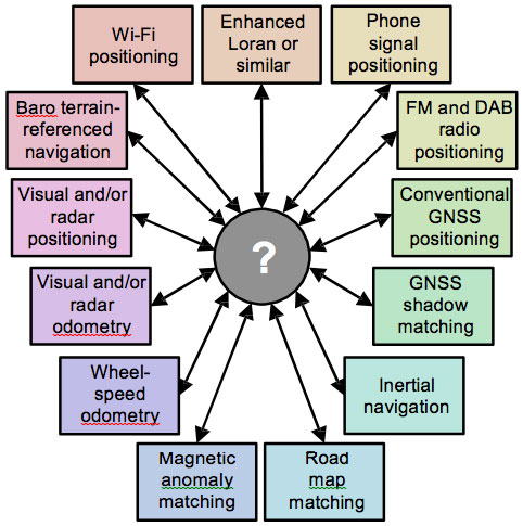
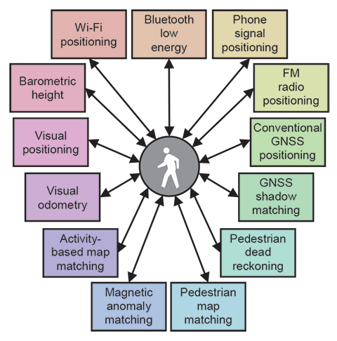
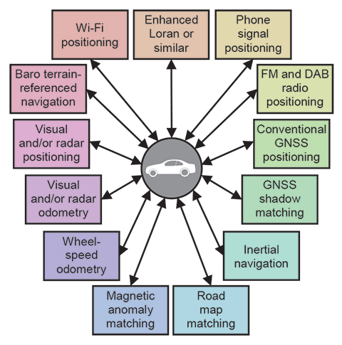
    Achieving robust positioning in challenging environments potentially requires a large number of subsystems. For example, Figure 1 shows the possible components of a pedestrian navigation system using sensors found in a typical smartphone. Figure 2 shows possible components of a car navigation system using equipment already common on cars and other suitable low-cost sensors. Some technologies are common to the two platforms, while others differ.

    Figure 1. Potential components of a pedestrian navigation system using smartphone sensors. (Photo: Paul D. Groves, Lei Wang, Debbie Walter, Henry Martin, and Kimon Voutsis, University College London)
    Figure 1. Potential components of a pedestrian navigation system using smartphone sensors. (Photo: Paul D. Groves, Lei Wang, Debbie Walter, Henry Martin, and Kimon Voutsis, University College London)
    Figure 2. Potential components of a car navigation system using commonly available equipment and other low-cost sensors. (Photo: Paul D. Groves, Lei Wang, Debbie Walter, Henry Martin, and Kimon Voutsis, University College London)
    Figure 2. Potential components of a car navigation system using commonly available equipment and other low-cost sensors. (Photo: Paul D. Groves, Lei Wang, Debbie Walter, Henry Martin, and Kimon Voutsis, University College London)

    Any multisensor navigation or positioning system needs integration algorithms to obtain the best overall position solution from the constituent subsystems. These algorithms must not only input and combine measurements from a wide range of subsystems, but also calibrate systematic errors in those subsystems. Designing the integration algorithms therefore requires expertise in all of the subsystems, which can be difficult to establish in a single organization. The more subsystems there are, the more of a problem this is.

    The expert knowledge problem is compounded by the fact that different modules in an integrated navigation system are often supplied by different organizations, who may be reluctant to share necessary design information if this is considered to be intellectual property that must be protected. In a typical smartphone, one company supplies the GNSS chip, another supplies the Wi-Fi positioning service, a third organization supplies the mapping, the network operator provides the phone-signal positioning, a fifth company provides the inertial and magnetic sensors, and a sixth company produces the operating system. Because of lack of cooperation between these different organizations, useful information gets lost. For example, GNSS pseudo-range measurements are not normally available to application developers.

    A further issue is reconfigurability. To minimize development costs, manufacturers share algorithms and software across different products, incorporating different subsystems. They also want to minimize the cost of adding new sensors to a product to improve performance. Similarly, researchers want to compare different combinations of subsystems. However, with a conventional system architecture, modifications must be made throughout the integration algorithm each time a subsystem is added, removed, or replaced. The more subsystems there are, the more complex this task becomes.

    For a given application, different subsystems may also be used at different times. For example, a smartphone may use Wi-Fi positioning indoors and GNSS outdoors and may deploy different motion constraints and map matching algorithms, depending on whether the device is carried by a pedestrian or traveling in a car. Different integration algorithms for different configurations are more processor efficient, but also require more development effort. Conversely, an all-subsystem integration algorithm is quicker to develop, but can waste processing resources handling inactive subsystems.

    Modular Integration. The solution to these problems is a modular integration architecture, consisting of a universal integration filter module and a set of configuration modules, one for each subsystem. The integration filter module would be designed by data fusion experts without the need for detailed knowledge of the subsystems. It would accept a number of generic measurement types, such as position fixes and pseudo-ranges, with associated metadata. The configuration modules would be developed by the subsystem suppliers and would convert the subsystem measurements into a format understood by the filter module and supply the metadata. They would also mediate the feedback of information from the integration filter to the subsystems. The metadata comprises the additional information required to integrate the measurements such as

    • the measurement type and any coordinate frame(s) used.
    • a sensor identification number (to distinguish measurements of the same type from different sensors).
    • statistical properties of the random and systematic measurement errors.
    • identification numbers and locations of transmitters and other landmarks.

    A key advantage of this approach is that subsystems may be changed without the need to modify the integration filter. Provided the new subsystem is compatible, all that is needed is the corresponding configuration module.

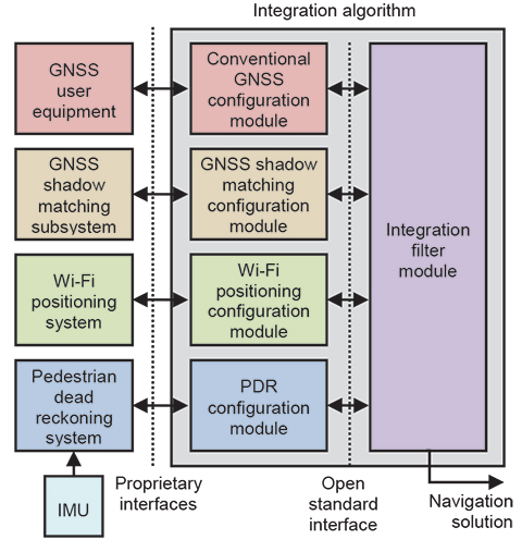
    Figure 3 shows an example of a modular integration architecture for a combination of conventional GNSS positioning, GNSS shadow matching, Wi-Fi positioning, and PDR. As well as providing measurements and associated statistical data to the integration filter module, the configuration modules feedback relevant information to the subsystems. Shadow matching works by comparing measured and predicted signal availability over a number of candidate positions, so requires a search area to be specified using other positioning technologies. PDR uses information from other sensors, where available, to calibrate the coefficients of its step length estimation model and correct for heading drift. Conventional GNSS positioning can also benefit from position and velocity aiding to support acquisition and tracking of weak signals in indoor and urban environments.

    Figure 3. Modular integration of conventional GNSS, shadow matching, PDR, and Wi-Fi positioning for pedestrian navigation (different colors denote potentially different suppliers). (Photo: Paul D. Groves, Lei Wang, Debbie Walter, Henry Martin, and Kimon Voutsis, University College London)
    Figure 3. Modular integration of conventional GNSS, shadow matching, PDR, and Wi-Fi positioning for pedestrian navigation (different colors denote potentially different suppliers). (Photo: Paul D. Groves, Lei Wang, Debbie Walter, Henry Martin, and Kimon Voutsis, University College London)

    In principle, each subsystem configuration module could simply supply a position fix to the integration filter module with an associated error covariance. However, other forms of measurement generally give better results. For conventional GNSS positioning, the advantages of tightly coupled (range- domain) integration over loosely coupled (position-domain) are well known.

    PDR is a dead-reckoning technique, so measures distance traveled rather than position. Consequently, providing measurements of position displacement and direction can avoid cumulative errors in the measurement stream.

    GNSS shadow matching and some types of Wi-Fi positioning use the pattern-matching positioning method. This scores an array of candidate position solutions according to the match between the measured and predicted signal availability or signal strength. Although the output of these algorithms is in the position domain, a likelihood distribution can provide more information for the integration filter than a simple mean and covariance.

    Other navigation and positioning techniques generate further types of measurement, including velocity, attitude, specific force, angular rate, range rate, and bearings and elevations of features. The types of measurement depend on the positioning method.

    A universal integration filter must operate without prior knowledge of which measurements it must process and which states it must estimate. Consequently, it must reconfigure its measurement vector, state vector, and associated matrices according to the measurements available, using the metadata supplied by the configuration module. This capability is sometimes called “plug and play,” and a number of prototypes have been developed by different research groups.

    The integration filter must be capable of implementing either error-state or total-state integration, depending on the measurements available. In error-state integration, one of the subsystems, such as inertial navigation, provides a reference navigation solution. The integration filter estimates corrections to that solution using the measurements from other subsystems. In total-state integration, the integration filter estimates the position and velocity directly, and an additional configuration module provides information on the host vehicle (or pedestrian) dynamics.

    Modular integration algorithms could form part of a wider modular integrated navigation concept in which subsystem hardware and software is shared across a range of applications.

    Issues to Resolve

    A critical requirement for the successful implementation of modular integration is an open-standard interface for communication between the universal filter and configuration modules. This enables modules produced by different organizations to work together. To realize the full benefits of modular integration, in terms of interoperability and software re-use, there should be a single standard covering the consumer, professional, research, and military user communities and spanning all of the application domains air, sea, land, indoor, underwater, and so forth. A standard developed by one group in isolation is unlikely to meet the needs of the whole navigation and positioning community, while the development of multiple competing standards defeats the main purpose of modular integration.

    This interface should be defined in terms of fundamental measurement types, such as position, velocity, and the ranges, bearings, and elevations of signals and features. However, there are many different coordinate systems that may be used and positioning may be in 2 or 3 dimensions, while ranging measurements may be true ranges or pseudoranges. Ranging and angular positioning measurements may be differenced across transmitters or landmarks, differenced across receivers or sensors, or double differenced across both.

    A universal interface must support every measurement type that requires different processing by the filter module. However, it need not support formats that are easily convertible. Thus, there is no need to support both the north, east, down, and east, north, up conventions. There are two main approaches to defining the fundamental measurement types:

    • A minimal number of very generic measurement types with metadata used to describe how these should be processed by the integration filter.
    • A large number of more specific measurement types for which the processing methodology is already known.

    For each measurement type, an error specification must be defined. For error sources assumed to be white, a standard deviation or power spectral density (PSD) is required. For correlated errors, such as biases, information on the time correlation is required alongside variances and covariance information. The interface standard should include every conceivable error source. Unused errors can simply be zeroed. The filter module should then use the error specification to determine which error sources to model and how.

    Obtaining reliable navigation sensor error specifications can be difficult. Manufacturers often provide only limited information, while performance in the field can be different from that in the laboratory due to vibration and electromagnetic interference. For new positioning techniques, the error behavior may not be fully understood, while complex error behavior can be difficult to measure. Adaptive estimation techniques provide only a partial solution. Even where the error behavior is well known, it can be too complex to practically model within the estimation algorithm. This could represent a fifth challenge.

    For subsystems used as the reference in an error-state integration filter, such as an inertial navigation system (INS), the errors will typically be correlated across the different components of the subsystem navigation solution, for example position, velocity, and attitude. Furthermore, to represent the error behavior within an integration algorithm, it is necessary to model the error properties of the underlying sensors, accelerometers and gyroscopes in the case of inertial navigation. Thus, it is likely that additional compound measurement types for reference system data will be needed.

    For pseudorange measurements, an issue to consider is the synchronization of different transmitter and receiver clocks. Clocks in receivers for different types of signal, such as GNSS and Loran, may or may not be synchronized with each other. Also, the transmitter clocks are typically synchronized in groups. For example, the GPS satellite clocks are synchronized with each other, as are the GLONASS satellite clocks, but GLONASS is not currently synchronized with GPS. For optimal integration of pseudoranges from different sources, this information must be conveyed to the integration filter.

    The interface standard for communication between the filter and configuration modules must also support feedback of information from the integration filter to the subsystems, via the configuration modules. The integrated position, velocity, and attitude solution, with its associated error covariance, is useful for aiding many different subsystems. Therefore, a generic standard for this should be defined. Conversely, the feedback to the subsystems of calibration parameters estimated by the integration algorithm is sensor specific, so should be incorporated in the definitions of the fundamental measurement types.

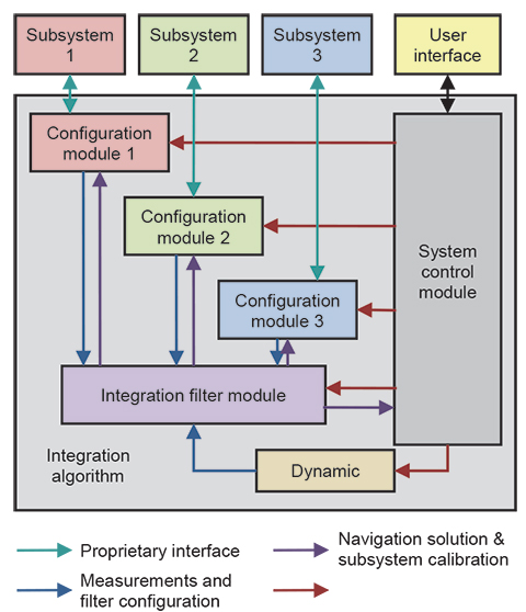
    The user requirements, such as accuracy, integrity, continuity, solution availability, update rate, and power consumption, can vary greatly between applications. For example, accuracy is important for surveying, integrity for civil aviation, solution availability for many military applications, and power consumption for many consumer applications. This impacts the design of the whole navigation system. Different modules could be used for different applications. However, it is more efficient if the components adapt to different environments. Figure 4 shows how requirements information can be disseminated in a modular integrated navigation system.

    Figure 4. Modular integration architecture incorporating requirements. (Photo: Paul D. Groves, Lei Wang, Debbie Walter, Henry Martin, and Kimon Voutsis, University College London)
    Figure 4. Modular integration architecture incorporating requirements. (Photo: Paul D. Groves, Lei Wang, Debbie Walter, Henry Martin, and Kimon Voutsis, University College London)

    An open-standard interface specification should be able to handle any conceivable navigation and positioning system. However, it is more efficient if the components adapt to different environments. Similarly, there will be differences in the error magnitudes that an integration filter can handle and in its capability to handle non-Gaussian error distributions. Variations in fault detection and integrity monitoring capability can also be expected. Consequently, there must be a capability specification for each filter module and a protocol for handling mismatches between the measurements and the filter module, and a means to certify that a filter module actually has the claimed capabilities. (Further discussion of modular integration may be found in our IEEE/ION PLANS 2014 paper, “The Four Key Challenges of Advanced Multisensor Navigation and Positioning,” and the Journal of Navigation paper, “The Complexity Problem in Future Multisensor Navigation and Positioning Systems: A Modular Solution.”)

    Context

    Context is the environment that a navigation system operates in and the behavior of its host vehicle or user. Examples include a pedestrian walking (behavior) in an urban street (environment), a car driving at highway speeds on an open road, and an airliner flying high above an ocean.

    Context is critical to the operation of a navigation or positioning system. The environment affects the types of signals available. For example, GNSS reception is poor indoors while Wi-Fi is not widely available outside towns and cities. In underwater environments, most radio signals cannot propagate so acoustic signals are used instead. Processing techniques can also be context dependent. For example, in open environments, non-line-of-sight (NLOS) reception of GNSS signals or multipath interference may be detected using consistency checking techniques based on sequential elimination. However, in dense urban areas, more sophisticated algorithms are required and may be enhanced using 3D city models. GNSS shadow matching only works in outdoor urban environments.

    Navigation using environmental feature matching is inherently context-dependent as different types of feature are available in different environments. Suitable algorithms, databases, and sensors must be selected. For example, terrain referenced navigation (TRN) uses radar or laser scanning in the air, sonar or echo sounding at sea, and barometric pressure on land. Map matching requires different approaches for cars, trains, and pedestrians. Similarly, algorithms and databases for image-based navigation depend on the types of feature available, which vary with the environment.

    Behavioral context is also important and can contribute additional information to the navigation solution. For example, cars normally remain on the road, effectively removing one dimension from the position solution. Their wheels also impose constraints on the way they can move, reducing the number of inertial sensors required to measure their motion. Similarly, PDR using step detection depends inherently on the characteristics of human walking. Using PDR for vehicle navigation or vehicle motion constraints for pedestrian navigation will produce errors.

    Host vehicle behavior is also important for tuning the dynamic model within a total-state navigation filter and for detecting faults through discrepancies between measured and expected behavior. Within a GNSS receiver, the behavior can be used to set tracking loop bandwidths and coherent correlator accumulation intervals, and to predict the temporal variation of multipath errors. The antenna placement on a vehicle or person can also affect performance.

    Historically, context was implicit; a navigation system was designed to be used in a particular type of vehicle, handling its associated behavior and environments. However, many navigation systems now need to operate in a variety of different contexts. For example, a smartphone moves between indoor and outdoor environments and can be stationary, on a pedestrian, or in a vehicle. Similarly, a small surveillance drone may operate from above, amongst buildings, or even indoors. At the same time, most of the new positioning techniques developed to enable navigation in challenging environments, are context-dependent. To make use of these techniques in practical applications (as opposed to research demonstrators), it is necessary to know the context.

    Context-Adaptive Navigation

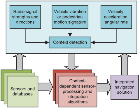
    The solution to the problem of using context-dependent navigation techniques in variable-context applications is context-adaptive navigation. As shown in  Figure 5, the navigation system detects the current environmental and behavioral context and, in real time, reconfigures its algorithms accordingly. For example, different radio positioning signals and techniques may be selected, inertial sensor data may be processed in different ways, different map-matching algorithms may be selected, and the tuning of the integration algorithms may be varied.

    Figure 5. A context-adaptive navigation system. (Photo: Paul D. Groves, Lei Wang, Debbie Walter, Henry Martin, and Kimon Voutsis, University College London)
    Figure 5. A context-adaptive navigation system. (Photo: Paul D. Groves, Lei Wang, Debbie Walter, Henry Martin, and Kimon Voutsis, University College London)

    Previous work on context-adaptive navigation and positioning focused on individual subsystems and concerned either behavioral or environmental context, not both.

    For example, there has been substantial research into classifying pedestrian motion using inertial sensors to enable PDR algorithms using step detection to estimate the distance travelled from the detected motion. The context information may also be used for non-navigation purposes.

    Typically, orientation-independent signals are generated from the accelerometer and gyro outputs. Statistics such as the mean, standard deviation, root mean squared (RMS), inter-quartile range, mean absolute deviation, maximum−minimum, maximum magnitude, number of zero crossings, and number of mean crossings are then determined from a few seconds of data. Frequency-domain statistics may also be used. Finally, a pattern recognition algorithm is used to match these parameters to the stored characteristics of different combinations of activity types and sensor locations.

    Detection of road-induced vibration using accelerometers has been used to determine whether or not a land vehicle is stationary, while a calibrated yaw-axis gyro can be used to determine when a vehicle is travelling in a straight line. Indoor and outdoor environments may be distinguished using GNSS carrier-power-to-noise-density ratio (C/N0 ) measurements. Wi-Fi signals might also be used for environmental context detection.

    Context Detection Experiments

    We have conducted a number of different context-detection experiments using GNSS, Wi-Fi, and accelerometers. Full details are presented in our ION GNSS+ 2013 paper, “Context Detection, Categorization and Connectivity for Advanced Adaptive Integrated Navigation,” and in our PLANS 2014 paper. Here, some highlights from the results are presented.

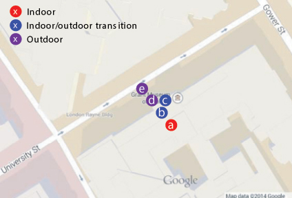
    GNSS. GNSS data was collected at five locations inside and immediately outside UCL’s Grant Museum of Zoology; these are shown in Figure 6. C/N0 measurement data was collected from all GPS and GLONASS signals received by a Samsung Galaxy S3 Android smartphone. About 60 seconds of data was collected at each site. Figure 7 presents histograms of the C/N0 measurements and Table 1 lists the means and standard deviations.

    Figure 6. Locations for the GNSS indoor/outdoor context detection experiment. (Photo: Paul D. Groves, Lei Wang, Debbie Walter, Henry Martin, and Kimon Voutsis, University College London)
    Figure 6. Locations for the GNSS indoor/outdoor context detection experiment. (Photo: Paul D. Groves, Lei Wang, Debbie Walter, Henry Martin, and Kimon Voutsis, University College London)
    Figure 7. GNSS C/N0 measurement distributions at sites inside and immediately outside UCL’s Grant Museum of Zoology. (Photo: Paul D. Groves, Lei Wang, Debbie Walter, Henry Martin, and Kimon Voutsis, University College London)
    Figure 7. GNSS C/N0 measurement distributions at sites inside and immediately outside UCL’s Grant Museum of Zoology. (Photo: Paul D. Groves, Lei Wang, Debbie Walter, Henry Martin, and Kimon Voutsis, University College London)
    Table 1. Means and standard deviations of GNSS C/N0 measurements inside and outside UCL’s Grant Museum of Zoology. (Photo: Paul D. Groves, Lei Wang, Debbie Walter, Henry Martin, and Kimon Voutsis, University College London)
    Table 1. Means and standard deviations of GNSS C/N0 measurements inside and outside UCL’s Grant Museum of Zoology. (Photo: Paul D. Groves, Lei Wang, Debbie Walter, Henry Martin, and Kimon Voutsis, University College London)

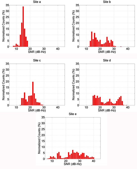
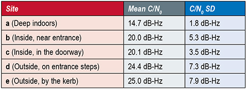
    As expected, the average received C/N0 is lower indoors than outdoors and lower deep indoors than near the entrance. Furthermore, the standard deviation of the C/N0 measurements is larger outdoors than indoors and also larger near the entrance to the building than deep indoors. Thus, both the mean and the standard deviation of the measured C/N0 across all GNSS satellites tracked are useful both for detecting indoor and outdoor contexts and for distinguishing between different types of indoor environment.

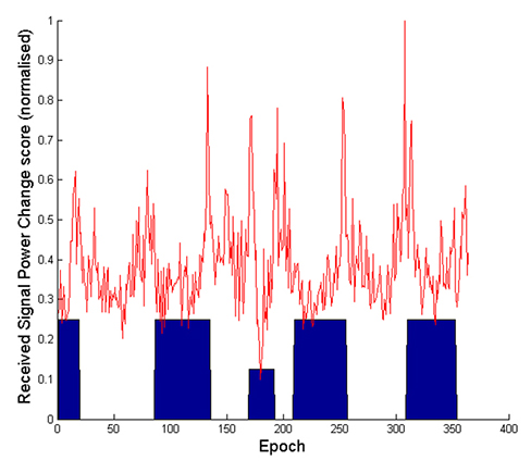
    Indoor/Outdoor Detection, Wi-Fi. Tests in and around several UCL buildings have shown no clear relationship between Wi-Fi SNRs and environmental context. However, as the environment changes, there is a rapid change in the Wi-Fi SNRs over a few epochs. For a user moving from inside to outside of a particular building, those signals which originate inside go from strong to weak, while many of those from neighboring buildings become stronger. Consequently, Wi-Fi signals could potentially be used to detect context changes instead of the absolute context. This is useful for improving the overall robustness of context determination.

    To test this, Wi-Fi data was collected using a Samsung Galaxy S3 smartphone along a route with both indoor and outdoor sections and a context-change score calculated from the last six epochs of data at 1-second intervals.

    Context-change score results are presented in Figure 8. The large blue blocks indicate when the user was outside and the smaller blue block shows when the user was in the building’s basement, a very different Wi-Fi environment. As can be seen, there are clear peaks in the “context change” score whenever the user moves between indoor and outdoor contexts.

    However, there are also peaks when the user enters and leaves the basement, so the technique is sensitive to false positives and must be combined with other context detection techniques to be used reliably.

    Figure 8. Context-change score computer from Wi-Fi SNR measurements. (Photo: Paul D. Groves, Lei Wang, Debbie Walter, Henry Martin, and Kimon Voutsis, University College London)
    Figure 8. Context-change score computer from Wi-Fi SNR measurements. (Photo: Paul D. Groves, Lei Wang, Debbie Walter, Henry Martin, and Kimon Voutsis, University College London)

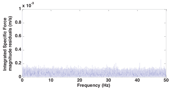
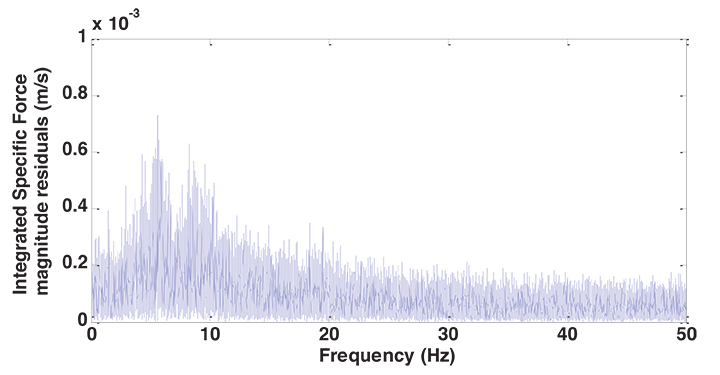
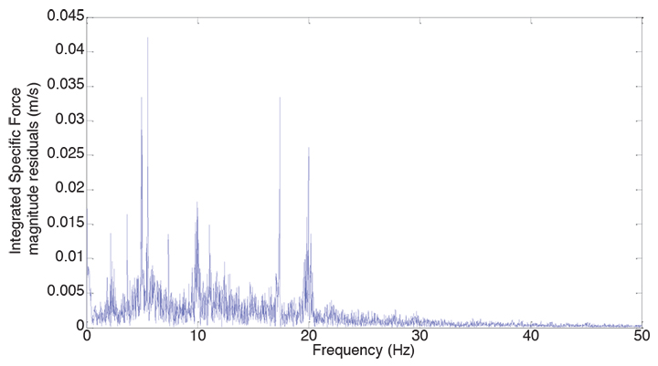
    Behavioral Detection, Accelerometers. The use of accelerometers to detect behavioral context is well established. However, by looking at the vibration spectra, more information can be extracted. For these experiments, specific force data was collected using an Xsens MTi-G IMU/GNSS device, the mean subtracted to remove most of the gravity, and a discrete Fourier transform obtained using the MATLAB function fft. Figures 9 and 10 respectively show the vibration spectra of the specific force magnitude for an IMU on a table and held by a stationary pedestrian. The table spectrum is approximately white, whereas the pedestrian data shows peaks between 6 and 10 Hz.

    Figure 9. IMU spectra on a table. (Photo: Paul D. Groves, Lei Wang, Debbie Walter, Henry Martin, and Kimon Voutsis, University College London)
    Figure 9. IMU spectra on a table. (Photo: Paul D. Groves, Lei Wang, Debbie Walter, Henry Martin, and Kimon Voutsis, University College London)
    Figure 10. IMU spectra, stationary pedestrian. (Photo: Paul D. Groves, Lei Wang, Debbie Walter, Henry Martin, and Kimon Voutsis, University College London)
    Figure 10. IMU spectra, stationary pedestrian. (Photo: Paul D. Groves, Lei Wang, Debbie Walter, Henry Martin, and Kimon Voutsis, University College London)

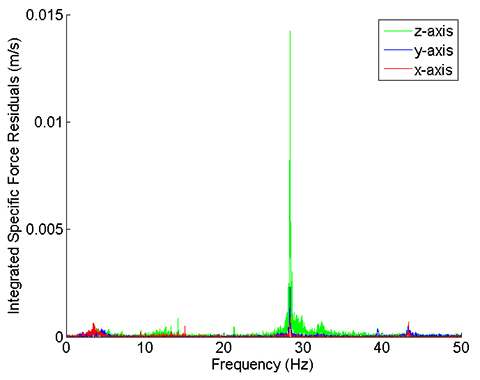
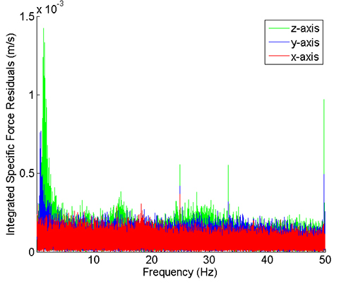
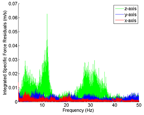
    Figures 11 and 12 respectively show the vibration spectra of a stationary Vauxhall Insignia car, and a stationary urban electric train. Here, the individual accelerometer spectra are shown. In each case, the x-axis was pointing forward, the y-axis to the right and the z-axis down. The car exhibits a lot of vibration at frequencies above 10 Hz due to its engine, whereas the dominant train vibration peak is around 1.5 Hz, with smaller peaks at 15 Hz, 25 Hz, 33 Hz, and 50 Hz, the mains power frequency. Thus, the two vehicles are very different from each other and also from the pedestrian. Figure 13 then shows the vibration spectrum of the car moving on a high-speed road. As might be expected, there is much more vibration when moving with broad peaks below 15 Hz due to road vibration and above 15 Hz due to engine vibration.

    Figure 11. Specific force frequency spectrum of a stationary car. (Photo: Paul D. Groves, Lei Wang, Debbie Walter, Henry Martin, and Kimon Voutsis, University College London)
    Figure 11. Specific force frequency spectrum of a stationary car. (Photo: Paul D. Groves, Lei Wang, Debbie Walter, Henry Martin, and Kimon Voutsis, University College London)
    Figure 12. Specific force frequency spectrum of a stationary train. (Photo: Paul D. Groves, Lei Wang, Debbie Walter, Henry Martin, and Kimon Voutsis, University College London)
    Figure 12. Specific force frequency spectrum of a stationary train. (Photo: Paul D. Groves, Lei Wang, Debbie Walter, Henry Martin, and Kimon Voutsis, University College London)
    Figure 13. Specific force frequency spectrum of a car traveling on a high- speed road. (Photo: Paul D. Groves, Lei Wang, Debbie Walter, Henry Martin, and Kimon Voutsis, University College London)
    Figure 13. Specific force frequency spectrum of a car traveling on a high- speed road. (Photo: Paul D. Groves, Lei Wang, Debbie Walter, Henry Martin, and Kimon Voutsis, University College London)

    Finally, Figure 14 shows the vibration spectra on an escalator at an underground rail station. The IMU was in the trouser pocket of a pedestrian. Vibration at a range of frequencies below 30 Hz can be seen and it was observed that the resonant frequencies vary between individual escalators.

    Figure 14. Specific force frequency spectrum on an escalator. (Photo: Paul D. Groves, Lei Wang, Debbie Walter, Henry Martin, and Kimon Voutsis, University College London)
    Figure 14. Specific force frequency spectrum on an escalator. (Photo: Paul D. Groves, Lei Wang, Debbie Walter, Henry Martin, and Kimon Voutsis, University College London)

    Issues to Resolve

    Despite the work done with individual sensors, a multisensor integrated navigation system that adapts to both environmental and behavioral context remains at the concept stage. Realizing this in a practical system requires both effective context determination and a set of context categories standardized across the whole navigation and positioning community.

    The first step in the standardization process is to establish a framework suitable for navigation and positioning. Each context category must map to a configuration of the navigation system; otherwise, it serves no purpose. Multiple categories may map to the same configuration as different navigation systems will respond to different context information. In an autonomous context-adaptive navigation system, the context categories must also be distinguishable from each other.

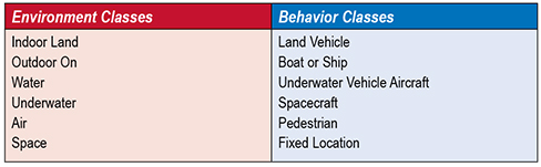
    Figure 15 shows the relationships in a five-attribute framework, comprising environment class, environment type, behavior class, vehicle type, and activity type. The environmental and behavioral contexts are treated separately because they perform fundamentally different roles in navigation. Environmental context concerns the availability of signals and other features that may be used for determining position whereas behavioral context is concerned with motion.

    Figure 15. Proposed attributes of a context category. (Photo: Paul D. Groves, Lei Wang, Debbie Walter, Henry Martin, and Kimon Voutsis, University College London)
    Figure 15. Proposed attributes of a context category. (Photo: Paul D. Groves, Lei Wang, Debbie Walter, Henry Martin, and Kimon Voutsis, University College London)

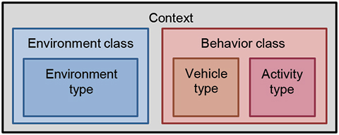
    Context may be considered at different levels. Sometimes it is sufficient to consider broad classes such as indoor or aircraft. In other cases, more detail is needed, specifying the type of indoor environment or the type of aircraft. Therefore, a two-level categorization framework, comprising class and type is proposed. The behavioral context comprises the vehicle type and the activity undertaken by that vehicle. A common set of classes containing separate vehicle and activity types is thus proposed. For pedestrian navigation, different parts of the body move quite differently, so the sensor location on the body is analogous to the vehicle type.

    The broad classes of environmental and behavioral context are relatively obvious. We therefore propose that the community adopts the classes in Table 2. Standardization at the type level requires further research to determine:

    • which context categories a navigation system needs to distinguish between in order to optimally configure itself;
    • which context categories may be distinguished reliably by context detection and determination algorithms.
    Table 2. Proposed environment and behavior classes. (Photo: Paul D. Groves, Lei Wang, Debbie Walter, Henry Martin, and Kimon Voutsis, University College London)
    Table 2. Proposed environment and behavior classes. (Photo: Paul D. Groves, Lei Wang, Debbie Walter, Henry Martin, and Kimon Voutsis, University College London)

    Effective Context Determination. The reliability of current context detection techniques is typically 90−99%, with some context categories easier to detect than others. For the purposes of controlling a navigation system, this is relatively poor. Furthermore, context detection research projects have typically considered a much smaller range of context categories than a practical context-adaptive navigation system would need. Generally, the more categories there are, the harder it is to distinguish between them.

    To make context determination reliable enough for context- adaptive navigation to be practical, a new approach is needed. Firstly, the context should be detected using as much information as possible, maximizing both the range of sensors used and the number of parameters derived from each sensor.

    Environmental context detection experiments have largely focused on GNSS and Wi-Fi signals. Other types of radio signal; environmental features detected using cameras, laser scanners, radar, or sonar; ambient light; sounds; odors; magnetic anomalies, and air pressure could all be used. Context may also be inferred by comparing the position solution with a map, provided both are sufficiently accurate.

    Behavioral context detection experiments have generally used inertial sensors. As shown earlier, this could be taken further by analyzing different frequency bands and, where possible, separating the forward, transverse, and vertical components. Other motion sensing techniques, such as visual odometry and wheel-speed odometry could be used. Context information, such as vehicle type, can also be determined from the velocity, attitude, and acceleration solutions.

    Considering every combination of environment type, vehicle type (or pedestrian sensor location), and activity type produces potentially tens of thousands of different context categories — too many to practically distinguish using context detection techniques alone. However, the number of context categories that must be considered may be reduced substantially by using association, scope, and connectivity information, making the determination process much more reliable.

    Association is the connection between the different attributes of context. Certain activities are associated with certain vehicle types and certain behaviors are associated with certain environments; an airliner flies, while a train does not, and flying takes place in the air, not at the bottom of the sea. 

    For a particular application, the scope defines each context category to be required, unsupported, or forbidden. This enables forbidden context categories to be eliminated from the context determination process and required categories to be treated as more likely than unsupported categories.

    Connectivity describes the relationship between context categories. If a direct transition between two categories can occur, they are connected. Otherwise, they are not. Thus, stationary vehicle behavior is connected to pedestrian behavior, whereas moving vehicle behavior is not because a vehicle must normally stop to enable a person to get in or out. Context connectivity is directly analogous to the road link connectivity used in map matching and a similar mathematical formulation may be used. In practice, it is best to represent the connectivity as continuously valued transition probabilities rather than in Boolean terms. This facilitates recovery from incorrect context determination and enables rare transitions between context categories to be represented.

    Location-dependent connectivity takes the concept a stage further by considering that many transitions between context categories happen at specific places. For example, people normally board and leave trains at stations and fixed-wing aircraft typically require an airstrip to take off and land. Thus context transition probabilities may be modeled as functions of the position solution, provided the positioning and mapping error distributions are adequately modeled and the probability of transitions occurring at unusual locations is considered.

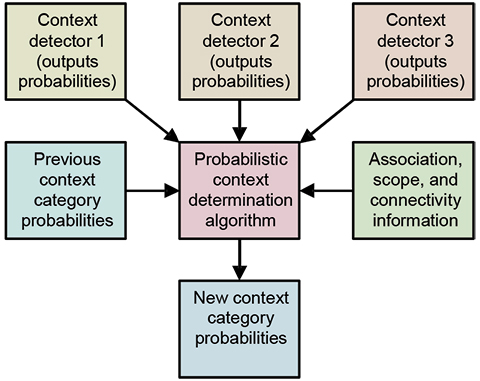
    Finally, for maximum robustness, the whole context determination process should be probabilistic, not discrete. The system should maintain a list of possible context category hypotheses, each with an associated probability. Multiple context detection algorithms should be used, each based on different sensor information. The detection algorithms should also output multiple context category hypotheses with associated probabilities. The context determination algorithm should then produce a new list of context category hypotheses and their probabilities by combining:

    • the previous list of hypotheses and their probabilities;
    • the hypotheses and probabilities output by the context detection algorithms;
    • context association, scope, and connectivity information.

    Figure 16 illustrates the concept. When there is insufficient information to determine a clear context category, the list of context hypotheses and their probabilities will be output to the navigation algorithms. The handling of ambiguous information in navigation systems is discussed in Part 2.

    Figure 16. Probabilistic context determination. (Photo: Paul D. Groves, Lei Wang, Debbie Walter, Henry Martin, and Kimon Voutsis, University College London)
    Figure 16. Probabilistic context determination. (Photo: Paul D. Groves, Lei Wang, Debbie Walter, Henry Martin, and Kimon Voutsis, University College London)

    Context Adaptivity and Integration

    The practical implementation of a complex multisensor navigation system for a multi-context application requires context-adaptive navigation to be incorporated into a modular multisensor integration architecture as described earlier. To enable different modules to adapt to changes in context, the architecture shown in Figure 4 should be extended to supply context information to the configuration modules, integration filter, and dynamic model from the system control module, alongside the user requirements. The configuration modules can then pass the context information onto the subsystems where necessary. Standardization of context categories and definitions across the navigation and positioning community is essential for this. Distribution of context information is useful even for single-context applications as it enables suppliers to provide modules that are optimized for multiple contexts.

    The modular integration architecture must also support the context detection and determination process, allowing all subsystems to contribute. The configuration modules should therefore provide context detection information to a context determination module, as shown in Figure 17. The scope information should be supplied by the system control module.

    Figure 17. Context-adaptive modular multisensor integration architecture. (Photo: Paul D. Groves, Lei Wang, Debbie Walter, Henry Martin, and Kimon Voutsis, University College London)
    Figure 17. Context-adaptive modular multisensor integration architecture. (Photo: Paul D. Groves, Lei Wang, Debbie Walter, Henry Martin, and Kimon Voutsis, University College London)

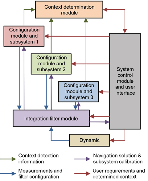
    Potential architectures for this are discussed in our PLANS 2014 paper.


    Ambiguity and Environmental Data

    Part 2 of this article, appearing in the November issue, explores the two remaining key challenges and forms conclusions and recommendations.


    Paul Groves is a lecturer at University College London (UCL), where he leads a program of research into robust positioning and navigation. He is an author of more than 50 technical publications, including the book Principles of GNSS, Inertial and Multi-Sensor Integrated Navigation Systems, now in its second edition. He is a Fellow of the Royal Institute of Navigation and holds a doctorate in physics from the University of Oxford.

    Lei Wang is a Ph.D. student at UCL. He received a bachelor’s degree in geodesy and geomatics from Wuhan University. He is interested in GNSS-based positioning techniques for urban canyons.

    Debbie Walter is a Ph.D. student at UCL. She is interested in navigation techniques not reliant on GNSS, multi-sensor integration and robust navigation. She has an MSci from Imperial College London in physics and has worked as an IT software testing manager.

    Henry Martin is a Ph.D. student at UCL. His project is concerned with improving navigation performance from a low-cost MEMS IMU.  He is interested in inertial navigation, IMU error modelling, multi-sensor integration and calibration algorithms. He holds a master of mathematics degree from Trinity College at the University of Oxford and an MSc in advanced mechanical engineering from Cranfield University.

    Kimon Voutsis is a Ph.D. student at UCL. He is interested in pedestrian routing models, human biomechanics, and positioning sensor performance under high accelerations, particularly IMUs and GNSS. He holds an MSc in geographic information science (UCL). His Ph.D. project investigates the effects of pedestrian motion on positioning.

    All authors are members of UCL Engineering’s Space Geodesy and Navigation Laboratory (SGNL).

  • KVH Introduces Fiber-Optic Gyro IMUs for Demanding Applications

    KVH Introduces Fiber-Optic Gyro IMUs for Demanding Applications

    KVH_1775_IMU-W KVH Industries, Inc.
    Photo: KVH Industries, Inc.

    KVH Industries, Inc., has introduced the 1725 Inertial Measurement Unit (IMU) and the 1775 IMU, advanced sensors designed to be integrated into the most demanding stabilization, pointing, and navigation applications. These two new products complement KVH’s successful 1750 IMU and create a complete range of choices for advanced six-degrees-of-freedom (DOF) sensors with enhanced performance. All three products utilize the E•Core ThinFiber technology of KVH’s DSP-1750 fiber-optic gyro (FOG).

    “With these three products, system designers and integrators now have a high-performance solution for every application — ranging from manned and unmanned commercial and defense platforms, optical equipment stabilization systems, and pipeline inspection equipment, to autonomous vehicle control and navigation,” said Jay Napoli, KVH’s vice president of FOG/OEM sales. “This line satisfies the performance, size, and price parameters for IMUs in a way that no competitor can match due to KVH’s control over the design and manufacturing process, from creating the fiber to integrating all of the IMU components into the final design. Maintaining complete control of this process, combined with our proprietary technologies, allows KVH to offer a winning combination of innovative solutions, superior quality, and affordable options for nearly every stabilization or guidance application.”

    The 1725 IMU features a flexible user interface, with user programmable data output rates from 1 to 1000 Hz. It delivers excellent FOG performance and stability at a price comparable to competitive MEMS-based IMUs. The 1725 IMU is designed for all platforms and navigation or stabilization systems where low cost, high-performance, and high bandwidth are critical for success.

    The 1775 IMU is a premium sensor designed to deliver the highest level of performance to meet the demands of platforms requiring superior performance in the most challenging environments. Providing ease of integration for designers of high-level inertial navigation, guidance, or stabilization systems, the 1775 IMU offers a flexible interface with user-programmable data output rates from 1 to 5000 Hz. It includes three axes of magnetometers for automatic gyro bias compensation even in the presence of strong magnetic fields. The 1775 IMU is designed for sophisticated systems and applications where very high bandwidth, low latency, and extreme stability are critical.

    Like KVH’s 1750 IMU, introduced in 2012, the 1725 IMU and the 1775 IMU incorporate three axes of KVH’s DSP-1750 FOG, a tiny high-performance FOG integrated with three axes of advanced accelerometer technology. All three IMUs provide excellent shock, vibration, and thermal performance, as well as a compact form factor, KVH said.

    KVH controls the entire production process, from creating its own specially designed polarization-maintaining optical fiber to packaging its gyros together in advanced systems for inertial measurement, inertial navigation, and attitude heading reference. As a result, KVH’s open-loop fiber optic gyros offer outstanding accuracy and excellent durability at a lower cost than competing systems, the company said.

  • Unicore Announces BeiDou/GPS+MEMS GNSS Module, High-Precision Heading Board at ION GNSS+

    UM220-INS BDS/GPS+MEMS dual-system inertial navigation module.
    UM220-INS
    BDS/GPS+MEMS dual-system inertial navigation module. Photo: Unicore

    Unicore Communications, Inc., is showcasing two new products at ION GNSS+, being held September 10-12 in Tampa, Florida.

    The UM220-INS is a BeiDou/GPS+MEMS dual-system inertial navigation module for in-dash automotive navigation and high-end navigation. Besides dual-system (BeiDou+GPS) GNSS navigation, the UM220-INS features a built in six-axis MEMS and can output a GNSS+MEMS inertial positioning result, making it suitable for applications requiring high accuracy, high reliability, and high continuity positioning.

    The second product is the UB280, a BeiDou/GPS dual-system dual-antenna high-precision heading board for precise RTK position and heading. According to Unicore, UB280 is based on Unicore’s mature BeiDou compatible multi-system GNSS system-on-chip (SoC), features low-power design and dual-antenna input, can offer millimeter-level carrier phase observation value and centimeter-level RTK positioning accuracy, and supports multi-path mitigation. Its advanced technology of instant and long-distance RTK is designed for high-precision positioning, navigation, and heading applications in static and dynamic environments.

    Features of the UM220-INS include:

    • Built-in six-axis MEMS. UM220-INS has a built-in MEMS with a 3-axis gyroscope and a 3-axis accelerometer. The solution fusing GNSS and inertial MEMS enables car-navigation devices to provide a continuous and stable position under complicated environments such as basement parking and tunnels, regardless of satellite visibility.
    • High-Sensitivity Design. With Unicore’s Ultra-Sense high-sensitivity design, UM220-INS can provide excellent acquisition and tracking sensitivity under weak signal conditions, maintaining the position continuity and reliability of the receiver.
    • High-Integrated Design. Different from traditional GPS navigation products, built-in MEMS devices support the odometer / speed pulse, the reversing signal input, and more integrated, simplified overall unit manufacturers’ design.
    • DGNSS and AGNSS Supprt. UM220-INS has extended support for differential GNSS and assisted GNSS positioning functions, and supports RTCM2.3/3.0.
    • Backward Compatibility with UM220. The UM220-III N module is backward-compatible with the UM220 in size and interface, which makes upgrades easy.
    UB280 BDS/GPS dual-system dual-antenna high -precision heading board. Photo: Unicore
    UB280 BDS/GPS dual-system dual-antenna high -precision heading board. Photo: Unicore

    Features of the UB280 incude:

    • Design standard. This board is totally compatible with mainstream OEM boards in dimensions and electrical standards for the convenience of user’s further development. Apart from this, more hardware interfaces are available.
    • Rapid RTK Integer Ambiguity Resolution. With super strong RTK algorithms, it ensures more rapid initializing speed and can make a GNSS-RTK solution on multi-constellation, thus ensuring users take the lead in the interoperability era.
    • Web Interface. The UB280 supports an Ethernet interface, so users can configure the board through Ethernet, managing, upgrading, and restarting the device remotely.
    • Instant Heading Technology. With an innovative RTK algorithm, Unicore has developed the real-time dynamic heading technology on variable baseline length for a moving base station. High-quality carrier observation and perfect RTK algorithm can provide a 0.2° heading accuracy on a 1-meter baseline.
    • Graphical Interface. Based on the graphical Control and Display Tool (CDT), the state, SNR and elevating angle of the satellites of all the constellations could be displayed on the screen, which is convenient for application development.

    Unicore Communications is located in Booth 118 in the ION GNSS+ exhibit hall.

  • Sensonor Showcases STIM300 IMU at ION GNSS+

    Sensonor Showcases STIM300 IMU at ION GNSS+

    The Sensonor STIM300 IMU.
    The Sensonor STIM300 IMU. Photo: Sensonor

    Sensonor will be showcasing its STIM300 Inertial Measurement Unit at Booth 102 at ION GNSS+.

    The STIM300 is a small, tactical-grade, low-weight, high-performance non-GPS aided IMU. It contains three highly accurate MEMS gyros, three high-stability accelerometers and three inclinometers. The IMU is factory calibrated and compensated over its temperature operating range.

    The STIM series is designed for use below and on the ocean, on land, in the air, and in orbit and space. The STIM300 IMU is well suited for stabilization, guidance and navigation applications in the industrial, aerospace and defense markets. It is a crucial building block for inertial navigation systems in UAVs, AUVs, AGVs, UGVs and ROVs, Sensonor said.

    The STIM300 is also used for camera turret stabilization and for use in various handheld devices that require a small IMU to secure operations during GPS outage.

  • SBG Systems Releases Ellipse Miniature Inertial Sensors

    SBG Systems Releases Ellipse Miniature Inertial Sensors

    SG Systems' IG-500 Series of miniature inertial sensors. Photo: SBG Systems
    SG Systems’ IG-500 Series of miniature inertial sensors. Photo: SBG Systems

    SBG Systems has released the Ellipse Series, a product range of miniature inertial systems replacing the IG-500 Series. For the same budget, customers benefit from higher accuracy, advanced filtering and features of high-end inertial navigation systems, the company said.

    The Ellipse Series of miniature inertial systems benefits from a new design, new sensors, new capabilities, and new algorithms. “We have selected state-of-the-art MEMS sensors, especially very low noise gyroscopes that greatly enhance Ellipse performance. We integrated cutting-edge GNSS receiver while keeping a small size,” said Alexis Guinamard, CTO of SBG Systems.

    “We are able to upgrade miniature sensors capabilities by injecting some advanced and proven filtering and features inspired from high end inertial navigation systems,” Guinamard said. Besides higher accuracy, SBG Systems added for the same budget an improved FIR and rejection filtering, robust IP68 enclosure, high output rate, RTK corrections, and automatic alignment.

    Weighting from 45 grams, Ellipse sensors are flexible. The Ellipse-A model provides 3D orientation and heave. For navigation, users can connect their own GPS receiver with the Ellipse-E, or use an internal receiver by choosing the Ellipse-N model. The larger Ellipse-D integrates a survey-grade L1/L2 GNSS receiver with two antennas for heading and position accuracy.

    Ellipse A, N, E models are available for order now. The Ellipse-D model will be available in the first quarter of 2015.

  • AT&T to Host Hackathon, Demonstrate Connected Platforms at CTIA

    AT&T will be a major participant during CTIA’s Super Mobility Week in Las Vegas next week. Connected car, connected home and wearables will all be on display throughout AT&T’s activities:

    • The first AT&T Hackathon to take place at CTIA will give developers access to new APIs for the car and home.
    • A 60-foot x 40-foot booth showcasing the latest Connected Life products.
    • A keynote address delivered by AT&T Mobile and Business Solutions President and CEO Ralph de la Vega and AT&T Mobility President and CEO Glenn Lurie, in which they will host a panel on the Future of Connected Car.

    AT&T Hackathon at CTIA 

    AT&T is kicking off the week’s events with its very first CTIA Hackathon, Code for Car and the Home, which will match developers with companies, tools and services to innovate in the connected car and automated home marketplace.  Developers will turn ideas into apps using APIs and other technology resources from 30-plus industry sponsors. More than 300 developers are expected to compete in the two-day Hackathon which begins at 10 a.m. PT on Saturday, September 6, in the Chelsea Theater at the Cosmopolitan Hotel. More than $100,000 in cash and prizes are available.

    Connected Life Booth

    When the Super Mobility Week show floor opens at 11 a.m. PT on Tuesday, September 9, AT&T will showcase the latest in wearables, connected cars and homes. Volvo and Audi will demo their connected car experiences and a simulator will be on-site to showcase AT&T Drive, the company’s connected car platform. AT&T Drive is a modular, global solution that allows automakers to pick and choose what services and capabilities are important to them in order to differentiate their solutions in the marketplace.

    Attendees can also explore how to stay connected to the home by visiting the AT&T Digital Life station. Digital Life is an all-digital, all-wireless automation and home security platform that equips customers with control of their homes from virtually anywhere.  On-site activations will include demos such as augmented reality so visitors can learn about the Digital Life service and products, an interactive wall to experience the simple, easy to use Digital Life app and a hologram home to showcase how Digital Life integrates everything you need in one place, to help make your life safer and easier, and provide you with more freedom to live your life.

    AT&T is the leader in emerging devices and will showcase the latest wearables from Fitbit, Jawbone, LG, Martian and Pebble. Additionally, Timex, the first authentic watch brand to enter the smartwatch space, will be on-site showcasing the new Timex Ironman One GPS+. The new smartwatch is the first GPS-connected fitness watch to connect to the mobile internet wirelessly, transmitting performance data, location, messages and more.

    Also on display will be the AT&T EverThere and FiLIP safety devices.  AT&T EverThere is a small wearable device that can detect falls and quickly identify location, automatically connecting the user to a 24/7 call center for response and support. FiLIP is a smart locater for kids that keeps parents and kids in touch at the push of a button.

    The  booth, number 4423, will be in the Connected Life section of the show floor at the Sands Expo and Convention Center. Visitors can locate the booth by using the interactive floor plan.

    Connected Car Keynote

    On Wednesday, Sept.10, Ralph de la Vega, president and CEO, AT&T Mobile and Business Solutions and Glenn Lurie, president and CEO, AT&T Mobility, will wrap up the show when they take the stage to discuss the Future of Connected Car.

    The following guest panelists will join them on stage to discuss this rapidly growing landscape:

    • Mary Chan, President, Global Connected Consumer, General Motors
    • Arun Bhikshesvaran, CMO, Ericsson
    • Mike Kennewick, Co-Founder and CEO, VoiceBox
    • Diarmuid O’Connell, VP, Business Development, Tesla Motors

    The keynote will kick off at 9 a.m. PT.

  • Multi-Constellation. Dual-Frequency. Single-Chip.

    Multi-Constellation. Dual-Frequency. Single-Chip.

    NAPA-OpeningFigure


    Fully Integrated NAPA Receiver Brings Mass-Market Potential

    This integrated circuit supports simultaneous reception and processing of the GPS L1/L5, Galileo E1/E5a, and GLONASS G1 signals with 40 tracking channels. The dual-band analog RF front-end is integrated on the same mixed-signal chip as the baseband hardware, including an embedded processor to close the tracking loops: overall, a compact, low-power, and low-cost solution.

    By Fabio Garzia, Stefan Köhler, Santiago Urquijo, Philipp Neumaier,Jörn Driesen, Sybille Haas, Thomas Leineweber, Tao Zhang, Sascha Krause, Frank Henkel,Alexander Rügamer, Matthias Overbeck, and Günther Rohmer

    Multi-constellation multi-band global navigation satellite system (GNSS) receivers can efficiently exploit the advantages derived from the modernization of existing GNSS constellations, such as GPS and GLONASS, as well as from the launch of new ones like Galileo and BeiDou. Utilizing multiple systems can significantly improve the availability of a navigation solution in urban canyons and heavily shadowed areas. Increased satellite availability also guarantees higher measurement redundancy and improved reliability. Moreover, the excellent inherent noise and multipath mitigation capabilities of the new and modernized wideband signals in the L5/E5a band, combined with the ionosphere error mitigation given by frequency diversity, significantly improves the accuracy in both measurement and position domains.

    Still, most commercial fully-integrated single-chip mass market GNSS receivers use only a single-frequency band for their positioning, velocity, time (PVT) solution: either GPS L1 C/A or Galileo E1 and GLONASS G1. For example, the Teseo chips are single-chip solutions that support multiple constellations but only on one frequency band. This approach reduces  design costs and enables the lowest consumption of power, but neglects the advantages of wideband signal processing  – which offers increased robustness thanks to  two simultaneous frequency band receptions and the capability of mitigating the ionosphere error.

    Another approach for realizing multi-constellation multi-frequency solutions is to combine different chips for the analog front-end and the digital baseband. One fully integrated single-chip analog multi-band front-end for the simultaneous reception of GPS L1/L5, Galileo E1/E5, and GLONASS has been presented. However, this chip included only the front-end and requires an additional, separate digital-baseband solution.

    The purpose of the NAPA project (NAvigation chip for Pedestrian navigation and higher precision Applications) is to close this gap by providing a fully integrated, compact, low-power, and low-cost solution in which the analog and digital parts of the GNSS receiver are integrated together on the same chip. The NAPA receiver offers all the advantages of multi-constellation reception with additional dual-frequency support.

    The NAPA chip features a monolithic, single mixed-signal chip implementation of a multi-system, multi-band analog front-end and the related digital baseband core, including an embedded processor. The NAPA chip can be used as a stand-alone GNSS sensor, because no additional components are required to obtain a PVT solution. The ASIC was implemented in a low-power technology and adopts some ad-hoc low-power architectural features. In regard to costs, an ASIC solution is more convenient than FPGA,  provided the non-recurring engineering costs (NRE) are amortized by the amount of chips manufactured and sold. The NAPA chip supports multi-system (GPS, Galileo, and GLONASS) and multi-band (GPS/Galileo L1/E1, L5/E5a, GLONASS G1) processing. Figure 1 shows the frequency band being selected for receiving and processing in the NAPA chip. With two fully deployed GNSS — GPS and GLONASS — NAPA chips can already be used in many commercial applications. Thanks to the spectral overlay of the GPS L1/L5 and Galileo E1/E5a signals, the chip is also ready for Galileo. The frequency selection features both the narrow-band legacy signals L1/G1, which can be used for fast acquisition. For highest tracking accuracy, the wideband GPS L5 and Galileo E5a BPSK(10) modulated signals can be utilized.

    Figure 1. GNSS signals received and processed by the NAPA chip.
    Figure 1. GNSS signals received and processed by the NAPA chip.

    The higher accuracy is  obtained primarily by the attenuation of the ionospheric error. The ionosphere is a dispersing media that can introduce a bias error between 1 and 20 m. Forming a linear combination of two independent frequency-band measurements, the ionospheric bias can be measured and almost completely removed. In addition, Precise Point Positioning and Wide/Narrow-laning combinations are possible, thanks to the second received frequency band. The first allows for the combination of precise satellite positions and clocks with multi-frequency measurements, providing cm/dm solutions. The second adopts fast ambiguity solutions for carrier-phase positioning and cycle-slip detection.

    In this article, we present the NAPA chip in detail. We describe the architecture of the analog front-end and its digital counterpart and the innovative features of each. Then we provide details about chip implementation, manufacturing, and test setup. Finally, we present the first verification results and draw conclusions.

    Architecture Overview

    The NAPA chip architecture, depicted in Figure 2,  is composed of two separate blocks integrated on the same silicon die: the analog core provides the functionality of a two-frequency radio-frequency (RF) front-end, whereas the digital part implements the main GNSS processing tasks, including the correlator channels and an embedded processor, and takes care of the RF front-end control. The interface between the two blocks is completely digital and provides synchronizers to ensure a valid clock domain crossing (CDC).

    Figure 2. Overall NAPA architecture with emphasis on the digital core blocks.
    Figure 2. Overall NAPA architecture with emphasis on the digital core blocks.

    Analog Front-End. The analog RF front-end supports the simultaneous reception of GPS L5 / Galileo E5a and GPS L1 / Galileo E1 / GLONASS G1 signals as well as modes where only one reception path is activated.

    Both passive and active GNSS antennas are supported, thanks to integrated low noise amplifiers (LNA). There are two separate signal reception paths for the two frequency bands. The L1/E1/G1 path is characterized by a quasi-zero-IF conversion that mixes the middle frequency between L1/E1 and G1 to zero frequency. The L1/E1 reception bandwidth is up to 14 MHz so as to incorporate the MBOC modulations of Galileo E1 and future GPS L1C signals. A programmable automatic gain control (AGC) controls the complex analog baseband signals before they are digitized with a 4-bit dual-channel analog digital converter (ADC).

    The second reception path receives an L5/E5a signal with up to 20 MHz bandwidth for the BPSK(10) modulated signals. This path uses a low-IF architecture. The signal is down-converted to an intermediate frequency (IF) of 15.345 MHz. The image frequency is suppressed by a polyphase filter. The real-valued analog signal is controlled by an AGC and converted to the digital domain using a single 4-bit ADC. A common phase locked loop (PLL) is used with specific L1/E1/G1 and L5/E5a dividers to generate the mixers’ local oscillator (LO) frequencies. The PLL loop filter is integrated on-chip to minimize external elements. Moreover, automatic filter and voltage-controlled oscillator (VCO) calibrations are included to mitigate process tolerances. The PLL can handle input clock frequencies between 10 and 80 MHz with a recommended clock frequency of 36.115 MHz.

    An SPI core was implemented on the front-end part to facilitate control of the different front-end features. This means it is possible to tune the PLL, to switch off a complete front-end path if the second frequency band is not used and to activate different on-chip calibration procedures.

    The frequency plan of the front-end is depicted in Figure 3. Due to the quasi zero-IF architecture, the complex L1/E1 baseband signal is located on an IF of -13.64 MHz and the GLONASS G1 frequency division multiple access (FDMA) signals on an IF of +12.94 MHz, with respect to the GLONASS G1 center frequency of 1602 MHz. The real-valued L5/E5a signals are provided by the second ADC and located on an IF of 15.345 MHz.

    Figure 3. RF front-end frequency plan.
    Figure 3. RF front-end frequency plan.

    The ADC samples are generated with a frequency of 74.4871875 MHz for both the single channel L5, as well as for the dual-channel L1/E1/G1 ADCs. The ADC clock is also directly connected to the baseband digital core and is used as the main clock for the GNSS hardware modules. The embedded processor in the digital core receives a second clock, which is twice as fast as the GNSS hardware one.

    Digital Baseband SoC. The baseband is characterized by a system-on-chip (SoC) architecture based on a SPARC-compatible 32-bit LEON2 microprocessor running at approximately 150 MHz. The GNSS functionality, including acquisition and tracking, are implemented using dedicated hardware modules.

    The processor’s primary functions are to correctly configure the RF front-end and control the different parts of the receiver. In particular, it triggers acquisition, initializes, and starts the tracking channels with the signals detected during acquisition and takes care of closing the frequency/phase/delay locked loops (FLL/PLL/DLL) used for signal tracking. The tracking loops have strict real-time constraints; communication between the channels and the processor features a high-speed infrastructure.

    Structurally, the processor is connected to a hierarchical on-chip Advanced Microcontroller Bus Architecture (AMBA) composed of a high-performance bus (AHB) and a peripheral bus (APB). The AHB provides a direct connection between the processor, the real-time GNSS modules, and the system memory, a monolithic 1 MByte block that hosts the main program at run-time. Different programs can be loaded if needed by using the external SD-card interface.

    In addition to the processor, there are four additional AHB masters: the bootloader, the SD-card controller, the real-time GNSS modules, and the on-chip processor debugger. The bootloader is in charge of the bus control at system start-up. The SD-card controller has integrated direct-memory access (DMA) capabilities to move data between the SD card and the system memory. The real-time GNSS modules can write the tracking results directly to the system memory. Finally, the integrated processor debugger allows real-time debugging and is used mainly in the verification phase. The APB provides a connection to generic peripherals, and control and status interface of the GNSS modules without real-time constraints, as well as the control and status interface of the RF front-end. Since the GNSS modules operate in a separate clock domain that runs at half the frequency of the processor domain, some synchronization logic is necessary to ensure correct CDC.

    The adoption of an SoC architecture provides  higher flexibility than conventional static hardware solutions. In addition to typical GNSS applications, the user can also implement some signal monitoring and processing algorithms in software. The eCos-embedded operating system is provided to ease software development.

    Generic Peripherals. The digital core is equipped with several peripherals that enable the communication with the outside world. The two separate universal asynchronous receiver/transmitter (UART) interfaces can run at 115.2 kbps. A dedicated serial peripheral interface (SPI) master is also provided with a maximum of 10-MHz clock frequency. For example, these interfaces can be used to provide NMEA data to some external display device or raw data (pseudoranges, code phases) in order to calculate a PVT solution. It is also possible to directly access the measurements generated from the correlator hardware and to control the tracking NCOs, which means users can choose their own algorithms for the loop closure. A possible application is the realization of vector-delay tracking using the NAPA ASIC and an external processor.

    The SD-card interface facilitates the loading and storage of large amounts of data, for example, memory codes and almanacs. The possibility of making signal snapshots periodically and saving them to an SD card for later analysis has also been foreseen. This could be useful in special applications in which the receiver hardware is not accessible to the user all of the time.

    In addition, 10 general-purpose I/O pins (GPIO) are provided. They can be controlled via software and can provide a very basic interface (for example, to connect to external LEDs or switches).

    Acquisition Module. The acquisition module adopts a parallel code phase search in the Fourier domain by using a 16-k Samples Fast Fourier Transform (FFT) core. The adopted algorithm is known as parallel code-phase search.

    The L1/E1/G1 signals coming from the front-end are first filtered and then sent to the acquisition module to allow a fast detection of the satellites in the L1/E1/G1 bands with their respective code delays and Doppler frequencies. The acquisition of GLONASS G1 FDMA signals is possible thanks to a software-configurable hardware mixer that can be set with the different G1 carrier frequencies. No direct hardware acquisition is supported for the L5/E5a band signals. The tracking of L5/E5a band signals is possible by performing a hand-over from L1/E1 band or a Tong search using the tracking channels.

    The acquisition process is performed iteratively over all the possible satellites and over a set of Doppler values. These values are obtained by dividing the complete range of possible Doppler variations into bins. The smaller these bins are, the more accurate the acquisition result, but the more time is required to complete the entire process.

    The acquisition has an additional layer of configurability because of the adoption of coherent and incoherent accumulations. These accumulations are supported in hardware but are completely software-controlled. This provides another possibility for achieving  higher accuracy, but at the cost of a larger execution time due to an increase in the amount of accumulations.

    To speed up acquisition, we introduced a dedicated logic based on a novel patented algorithm. With this algorithm, we are able to detect the Doppler of the L1/E1 satellites present in the signal with an accuracy of 2 Hz. By performing this Doppler search step before the actual acquisition, we are able to generate a list with Doppler values that can be used instead of the bins. This gives more accurate results thanks to the algorithm’s inherent accuracy (see Figure 4) and allows a reduction in the acquisition time since the amount of Doppler values are usually smaller than the bins. Another advantage of this algorithm is the possibility to detect the transition to an indoor context (such as where there is a lack of satellite signals) by simply  looking at the Doppler list, without performing any acquisition.

    Figure 4. Comparison between standard and Doppler-list based acquisition of an L1 signal.
    Figure 4. Comparison between standard and Doppler-list based acquisition of an L1 signal.

    A single iteration step for the acquisition of a GPS L1 signal requires no more than 1 ms for each accumulated epoch. To achieve a good compromise between accuracy and speed, we typically use four epochs of incoherent accumulation, which means approximately 4 ms execution time. For Galileo L1 with four incoherent accumulations, an iteration step takes approximately 16 ms. This time has to be multiplied by the number of satellites and bins to estimate the execution time of the complete process.

    Integrated Acquisition Memories. The acquisition module is characterized by dedicated memory blocks used for the fast FFT processing. It also provides the possibility to use these on-chip memories to store a snapshot of the incoming signals. In particular, we can store up to 81,920 samples of raw data for the complex L1 and real L5 IF signals for further analysis or processing, even off-chip. This enables sophisticated spoofing detection methods, for example, as well as interferer detection and characterization methods. Spoofing detection can be implemented by monitoring the 2D-acquisition search space. Interferer detection and characterization can employ short-time Fourier transforms (STFT) on the snapshot.

    Using the chip as a simple snapshot receiver without having to use the on-chip dedicated GNSS hardware is also a possibilty. For this purpose, the integrated peripherals like UART and SPI ports are provided as interfaces.

    Tracking Module. The 40 versatile tracking channels can be mapped to any combination of GPS, Galileo, and GLONASS signals on the two reception bands. One possible combination would be to track 10 GPS and 10 Galileo satellites simultaneously on both L1/E1 and L5/E5a bands. Alternatively, the user can include GLONASS signals by using fewer GPS / Galileo combinations. The assignment of these tracking channels to the actual GNSS signals can be changed at run-time in order to adapt to different reception situations or to assist the selected signal processing methods.

    Each channel is characterized by a five-tap correlator. For the BPSK modulated signals without side peaks, such as GPS L1/L5, Galileo E5a, and GLONASS G1, we use only three values (early, late, and prompt). For Galileo E1 BOC(1,1) signals, five values are foreseen (very early and very late in addition to the previous), so that false peak lock conditions can be detected and a bump-jumping algorithm can be applied. The switch between these modes can be done at run-time and determines the amount of correlation values to be exchanged between correlators and processor.

    Low-Power Features. The GNSS modules operate in their own clock domain. This clock domain is divided in clock-gated regions. There is a common region for the bus interfaces, one region for the acquisition, and one for each tracking channel. This allows a fine-grain shut-down of the GNSS modules that are not currently in use. For example, the acquisition can be deactivated when there are enough signals in tracking or the unused tracking channels can be disabled. This allows a reduced power consumption for the idle modules. This activation/deactivation procedure is controlled through a set of registers connected to the APB and is performed via software.

    External Front-End Interface. To allow for more flexibility, we provided an additional RF front-end interface. The interface is also depicted in Figure 3. This interface features one 2-bit complex and an additional 2-bit real input, as well as a clock input. The user can decide to directly connect the digital baseband core to an external RF front-end with compatible sampling rate parameters, and exclude the on-chip RF front-end. This makes it possible to use the NAPA chip for validating other RF front-end devices, or it can be adapted to special customer needs.

    Boot-Up Sequence. The SoC includes a hard-coded bootloader that is in charge of the bus control at start-up. In this phase, the processor is switched off. The bootloader loads a 24-kByte program from the SD-card to the system memory and starts the processor. In this phase, the processor runs with the external oscillator clock. Having performed the RF front-end initialization, the processor can switch to the front-end PLL generated processor clock that runs at approximately 150 MHz. This switch is completely transparent to the processor. Then the actual main GNSS receiver program is loaded into the system memory and executed.

    The NAPA Chip

    The NAPA chip has been manufactured in a low-power 1.2 V 65 nm TSMC technology. The 4.5 mm x 5.0 mm chip die was mounted in a QFN68 package; first test samples are available. The core requires a 1.2 V power supply, the pads 1.8 V. Figure 5 shows a picture of the die and its interconnections. The two parts, the analog core and the digital baseband, are clearly distinguishable. The chip is currently in the verification phase.

    Figure 5. NAPA chip.
    Figure 5. NAPA chip.

    Within the project, the development and testing of the NAPA design was carried out on basically two platforms. During the hardware development phase, the baseband core has been prototyped on a FPGA device and tested using a special file-player setup, as explained in the following section. Having taped out the chip and received the first samples from the foundry, a test board has been developed in order to verify NAPA chip functionality.

    FPGA Test Setup. In the development phase, the NAPA baseband core has been implemented on a Xilinx Virtex6 FPGA device. A Xilinx ML605 development board has been used for the test setup. The main limitation of the testing in this phase was the lack of an analog RF front-end prototype. In order to make  early testing of GNSS functionality possible, we adopted a file player developed by Fraunhofer IIS in a previous project. This file player uses a desktop PC to reproduce a digital signal data-stream stored in a binary file on the PC. The stream is sent through a dedicated interface to a commercial digital acquisition board. This board receives a clock synchronized with the baseband core’s clock in the FPGA and delivers the signals directly to the FPGA pins. The complete setup is depicted in Figure 6. The setup in use can be seen on the left part of the opening figure.

    Figure 6. FPGA test setup.
    Figure 6. FPGA test setup.

    Test Board. In the verification phase, which is currently ongoing, the first unpackaged test chip dies have been glued directly to the test PCB and bonded on board without any housing. After receiving the packaged chips, the QFN68 could be regularly soldered on the PCB. A block diagram of the board is depicted in Figure 7. The board hosts the typical switch buttons and LEDs for quick control and status detection as well as some specific interfaces. The clock can be provided through a dedicated SMA clock connector as well as a discrete oscillator. Two sub-miniature push-on (SMP) connectors are also provided for separate the L1 and L5 antenna inputs. The two UART ports, the debugger UART, and the SPI master port are connected using a FTDI chip. This chip allows the simultaneous connection of these ports to a desktop PC’s USB port. A parallel connector is provided to interface external front-end ADC signals and clock. The GPIOs are accessible through the same connector. A dedicated socket is added for a mini-SD card.

    Figure 7. Block diagram of NAPA test board.
    Figure 7. Block diagram of NAPA test board.

    Preliminary Results

    The chip on the test board was first tested  using the same file player of the FPGA setup. This way, we could evaluate the correct functionality of the digital baseband core without the need to activate and configure the on-chip front-end. After the successful tests, we focused on the on-chip front-end configuration, and we used the antenna connectors to provide valid GNSS signals. We tested the chip using three different configurations: a GNSS signal simulator, a static roof antenna, and a small active patch antenna.

    In the three configurations, we successfully acquired GPS L1 and Galileo E1 signals. We were also able to perform tracking on GPS L1 and L5I, as well as Galileo E1b and E5aI. Figure 8 shows the spectrum of a snapshot of L1 and L5 paths made using the on-chip dedicated snapshot hardware and sent through the UART port with a dedicated binary protocol for offline processing. For this special test, we used an arbitrary waveform generator to provide noiseless Galileo and GLONASS signals in the L1 and L5 frequency bands, supported by the NAPA chip. After performing a FFT of the two snapshots, we can clearly see these signals. In the L1 plot, the E1b signal is present in the negative frequency range with the two peaks typical of the BOC(1,1) modulation. The FDMA GLONASS G1 is in the positive frequency range with its trapezoidal characteristic. It is also possible to see a side lobe of the E1a BOCcos(15,2.5) in the proximity of the zero frequency. In the L5 plot, we can see the main peak of BPSK E5a signal on the right and its mirrored image on the left, due to the fact that L5 signal path is real.

    Figure 8. Spectrum of L1 and L5 band showing a Galileo E1 and E5a signal.
    Figure 8. Spectrum of L1 and L5 band showing a Galileo E1 and E5a signal.

    Acknowledgment

    This project has been funded by the Bundesministerium für Bildung und Forschung (BMBF) (German Federal Ministry of Education and Research), which is gratefully acknowledged.

  • A Long Look at Advanced Multisensor Navigation and Positioning

    A modern-day fable related by Steven Covey tells of a civil engineer leading a crew engaged in building a road through a dense jungle. Each day the engineer’s adept management, the crew’s motivation and energy, and the high-tech equipment at their disposal pushed the new road well beyond scheduled targets. Midway through the allotted month, the engineer decided to climb to the top of a tree to see if he could get a distant glimpse of the destination. After a few minutes, he called down to his crew, “Wrong jungle!”

    This comes to mind as we consider the well-known fact that the next generation of navigation and positioning systems must provide greater accuracy and reliability in a range of challenging environments, to meet the needs of a variety of mission-critical applications. It’s no secret that not a single navigation technology, among scores available to us, is robust enough to meet these requirements by itself. A multisensor solution is required.

    Although many new navigation and positioning methods have been developed in recent years, little has been done with all-encompassing vision to bring them together into a robust, reliable, and cost-effective integrated system. Almost all the solutions proposed — and I have conveyed many of them in the pages of GPS World, thanks to the expert engineers who designed and tested them — spring from the requirements of a particular situation, application, or industry sector. Their parameters are suitably specialized.

    What’s been lacking so far is an over-architecture for the entire field. Paul Groves of University College London has outlined such a structure in an article that will appear in the September issue of the magazine: “Four Key Challenges to Multisensor PNT.” This material was first presented at the IEEE/ION Position Location and Navigation Symposium (PLANS) in Monterey, California in May of this year.

    The magazine article will describe each challenge in turn. In each case, Groves explains the problem, proposes one or more solutions, and identifies the issues that must be resolved in order to implement those solutions. He also presents the results of some preliminary context-detection experiments and illustrates some of the problems using results from several UCL research projects. The discussion is illustrated with results from research into urban GNSS positioning, GNSS shadow matching, environmental feature matching, and context detection

    The four challenges: complexity, context, ambiguity, and environmental data handling.

    • Complexity – How to find the necessary expertise to integrate a diverse range of technologies, how to combine technologies from different organizations that wish to protect their intellectual property, how to incorporate new technologies and methods without having to redesign the whole system and how to share development effort over a range of different applications.
    • Context – How to ensure that the navigation system configuration is optimized for the operating environment and host vehicle (or pedestrian) behavior when both are subject to change.
    • Ambiguity – How to handle multiple hypotheses, including measurements of non-unique environmental features, pattern-matching fixes where the measurements match the database at multiple locations, and uncertain signal properties, such as whether reception is direct or non-line-of-sight (NLOS).
    • Environmental Data Handling – How to gather, distribute, and store the information needed to identify signals and environmental features and define their points of origin or spatial variation.

    As Groves relates in his article, many new positioning techniques have been investigated over the past fifteen years.

    • Wi-Fi positioning
    • Ultra-wideband (UWB) positioning
    • Positioning using phone signals
    • Positioning using television signals and other signals of opportunity (SOOP)
    • Bluetooth low energy positioning
    • Laser-based position fixing and dead
    • Pedestrian dead reckoning (PDR) using step detection
    • Pedestrian map matching Error! Reference source not found.
    • Magnetic anomaly matching
    • Activity-based map matching
    • GNSS shadow matching

    There have also been improvements to existing technologies.

    • Hardware required for visual navigation
    • Micro-electro-mechanical systems (MEMS) technology
    • Cold-atom technology and nuclear magnetic resonance (NMR) gyros offering aviation-grade performance with compact sensors
    • Legacy radio navigation systems, such as Distance Measuring Equipment (DME) and Loran (in Europe and South Korea) are being modernized
    • Doppler positioning is being reintroduced using Iridium communication satellites

    Finally, GNSS itself has been enhanced through multiple constellations in a continual state of upgrade and renewal, high-sensitivity receivers and network assistance, and augmentation by commercial pseudolite systems.

    Maybe it’s time for a high-level perspective on all these adjoining jungles, if we want to find our way out of them.

    Potential components of a car navigation system using commonly available equipment and other low-cost sensors.
    Potential components of a car navigation system using commonly available equipment and other low-cost sensors.
  • Visual Intelligence Releases iOne STKA for UAV Mapping Apps

    Visual Intelligence has announced that its iOne Software Sensor Tool Kit Architecture (iOne STKA) is available for purchase or licensing by manufacturers of unmanned airborne vehicles (UAVs) who want to deliver an integrated UAV/geospatial imaging solution to customers.

    Capturing high-resolution imagery for applications in engineering, construction, urban planning, military missions and other uses is a significant emerging market for UAV manufacturers, and Visual Intelligence’s iOne STKA makes it possible to bring high-resolution geospatial sensors to UAVs, the company said. By purchasing or licensing Visual Intelligence’s geospatial imaging platform, UAV companies can meet emerging demand for geoimaging solutions that combine the benefits of UAVs with the imaging capabilities of a geoimaging platform.

    iOne STKA provides the technology foundation to configure a variety of multi-purpose sensors, including miniaturized 2D/3D applications, for the emerging UVS and mobile/handheld markets. The iOne STKA received the Geospatial Forum 2013 World Technology Innovation in Sensors Award, is the first to be considered for NEANY’s Arrow UAV, and is field-proven by the commercial large-format 2D/oblique/3D multipurpose metric mapping systems iOne IMS, iOne Stereo, and iOne n-Oblique.

    With the iOne STKA, the same UAS/UAV sensor system architecture can be used for agricultural and forestry mapping, pipeline or corridor monitoring, utility assessments, aerial surveys, research, persistence surveillance and other metric 2D/3D professional applications. The iOne STKA is a modular multipurpose sensor platform reconfigurable for UAVs of any size. With the iOne STKA, UAV manufacturers are no longer limited to offer monolithic, single purpose DSLR type cameras. Using the iOne STKA technology, UAV end users can economically collect high-quality color or infrared NADIR, oblique, or video imagery as well as co-mount and co-register e.g., LiDAR and thermal sensors using the same system architecture.

    “By providing UAV manufacturers and end-users with one reliable and performing end-to-end standard digital sensor system solution for MANY applications, we are empowering our customers with a more efficient and standard technology foundation and paradigm to grow their business, enhance their products, and maximize their return,” said Visual Intelligence President and CEO Dr. Armando Guevara.

    At the core of the iOne STKA is Visual Intelligence’s Patented Advanced Retinal Camera Array (ARCA). Developed using open systems and object-oriented software engineering principles, the ARCA is “encapsulated” with a rich set of advanced proprietary software methods that integrate camera components. The ARCA enables the collection of different types of imagery, fused in one pass, producing low-cost, extremely accurate, high-resolution products. It also enables unprecedented array-based collection and functional scalability sensor fusion. The arrays made of these varied imaging devices perform like a single camera, producing one single metric, radiometrically and geometrically correct image, or set of co-registered and fused images; such as a Virtual Frame, of higher accuracy, resolution and quality than DSLR-based monolithic cameras.

    Adds Guevara, “UAV manufacturers can take advantage and offer bundled with the iOne sensors Visual Intelligence’s advanced computing technology for fast cloud-based basic and advanced actionable information product generation. As a fully automated solution (from the sensor to the cloud), the iOne STKA includes processing software that uses streamlined workflows and processes imagery faster with multicore/multithreaded/GPU computing technology, making it easy to quickly produce and analyze products in a device-content eCosystem environment. This technology/business model is designed to provide UAV manufacturers and users recurrent ROI.”

    UAVs built using sensors based on the iOne STKA have the following features and advantages:

    • Strong digital obsolescence resilience, extending the useable life of the system while improving operational efficiencies and reducing operating costs for an even better ROI.
    • In the field:
      • Collection scalability
      • Functional scalability
      • Sensor reconfiguration, e.g. increase collection or functionality as needed or per mission requirements.
    • Large cross-track and FOV collection through smaller aperture (ARCA enabled).
    • Ability to collect different sources of metric imagery that can be fused in one pass.
    • Sensor fusion: Ability to co-mount and co-register in a “small and tight packaging” the EO capability with any other EO or active sensor such as LiDAR, Thermal, IR, etc.

    The iOne STKA software architecture is normative across all ARCA-based products; that is, the software is the same for different array configurations or sizes. This reusable component approach yields economies of scale in the manufacturing and use of multipurpose UAV/sensor configurations.

  • KVH Precision Sensors Chosen by Geodetics for Inertial Navigation Systems

    KVH Precision Sensors Chosen by Geodetics for Inertial Navigation Systems

    The Geo-iNAV Advanced is a fully integrated GPS-aided inertial navigation system that utilizes KVH’s 1750 IMU to provide a high-performance navigation solution.
    The Geo-iNAV Advanced is a fully integrated GPS-aided inertial navigation system that utilizes KVH’s 1750 IMU to provide a high-performance navigation solution.

    KVH Industries, Inc., has entered into a strategic partnership with Geodetics Inc., developer of real-time, high-precision position and navigation solutions. The goal is to provide high-performance positioning and navigation products for commercial applications requiring high levels of precision, from unmanned platforms to terrestrial navigation.

    Geodetics is integrating the KVH 1750 inertial measurement unit (IMU) into two solutions: Geo-iNAV Advanced, a GPS-aided inertial navigation system; and Geo-RelNAV, a high-accuracy relative navigation, positioning, and orientation system. The KVH 1750 IMU provides highly accurate 6-degrees-of-freedom angular rate and acceleration data, contributing to the high performance of the Geodetics products while also providing a commercial off-the-shelf (COTS) solution. The COTS designation means the Geo-iNAV Advanced system is available for commercial applications such as manned and unmanned aircraft and control, security platforms on land, air and sea, surface or subsea unmanned vehicles, mobile mapping systems, and photogrammetry and terrestrial navigation.

    As reported April 9, NovAtel, Inc., has added the KVH 1750 as an inertial measurement unit (IMU) option in its SPAN GNSS/INS line of positioning products.

    “Geodetics evaluated a number of IMU technologies, and based on our desire to address the needs of the commercial marketplace worldwide without sacrificing performance, we chose the KVH 1750 IMU, says Dr. Jeffrey Fayman, vice president, planning and development for Geodetics Inc. “With the integration of the KVH 1750 IMU in Geo-iNAV Advanced, you have the best inertial navigation system Geodetics can provide worldwide.” The navigation, position, and orientation accuracy of the Geo-iNAV Advanced is centimeter level, according to Fayman, thanks in part to the high accuracy of the KVH 1750 IMU.

    “KVH is proud to have a strategic relationship with Geodetics,” says Jay Napoli, vice president, FOG/OEM sales at KVH. “The high performance of the 1750 IMU helps enable Geodetics’ systems to deliver ground-breaking accuracy while remaining available to the commercial marketplace.”

    For navigation challenges such as collision avoidance and vehicle-to-vehicle navigation and communication (V2V), the Geodetics Geo-RelNAV system offers a highly accurate, real-time relative positioning and orientation solution that utilizes single- or dual-frequency GPS receivers and the high performance KVH 1750 IMU. The Geo-RelNAV provides precise relative position and orientation between moving platforms such as manned or unmanned air, marine, and ground vehicles. This relative position data is used for such applications as autonomous aerial refueling, autonomous landing, and collision avoidance.

    KVH is one of the only fiber optic gyro manufacturers to control the entire production process, from creating its own specially designed polarization-maintaining optical fiber to packaging its gyros together in advanced systems for inertial measurement, inertial navigation, and attitude heading and reference systems. As a result, KVH’s inertial sensors and gyros offer outstanding accuracy and excellent durability at a lower cost than competing systems.

  • Qualcomm Offers Commercial Advanced Chipset for Automotive

    Qualcomm Technologies, Inc., has added the Qualcomm Gobi 9×30 platform with extended lifecycle support to Snapdragon Automotive Solutions, enabling advanced telematics and infotainment features for next-generation systems.

    The announcement was made at Mobile World Congress, being held this week in Barcelona, Spain.

    Based on Qualcomm Technologies’ fourth-generation LTE platform, the Gobi 9×30 supports LTE Advanced Category 6 with up to 300 Mbps downlink data rates, enabling broadband vehicle connectivity for enhanced navigation, Wi-Fi hotspot, infotainment content and telematics services.

    Gobi 9×30 builds upon Qualcomm Technologies’ LTE modem technology for automotive, the Gobi 9×15, and promises to enable a superior next-generation GNSS engine and fast 3G and 4G LTE connections worldwide, while supporting broad multi-region coverage in a single SKU with the Qualcomm RF360 front-end solution. The Gobi 9×30 is based on the 20-nm technology node with support for global carrier aggregation deployments up to 40 MHz in both LTE FDD and TDD modes. The Gobi 9×30 features broad multi-mode capability with support for all other major cellular technologies, including LTE TDD networks in China.

    In addition to 3G/LTE connectivity, the new platform is pre-integrated with QCA6574, a dual-stream 802.11ac Wi-Fi and Bluetooth 4.1 chipset designed to simultaneously support in-car Wi-Fi hotspot functions and Bluetooth profiles. The QCA6574 also supports DSRC (dedicated short-range communications), a technology required to comply with future regulation recently announced by the National Highway Traffic Safety Administration (NHTSA) to increase safety through vehicle-to-vehicle (V2V) communication. The Gobi 9×30 and QCA6574 will also be pre-integrated with Qualcomm Technologies’ recently-announced automotive-grade Snapdragon 602A processor.

    “The need for high-speed connectivity in the automobile is driving ever-increasing data rates as well as greater integration of features and technologies,” said Kanwalinder Singh, senior vice president of business development for Qualcomm Technologies, Inc. “Adding Gobi 9×30 to our technology leading LTE lineup offers to our module, Tier-1 and automaker customers the flexibility of a global SKU with next-generation LTE features including data rates up to 300 Mbps and carrier aggregation. The Gobi 9×30 sets a new bar for features and integration: 20 nm technology node; support for both LTE FDD and TDD modes; built-in next-generation GNSS engine; pre-integration with Snapdragon 602A; and pre-integration with QCA 6574, supporting 802.11ac, BT 4.1, and DSRC.”

    Gobi 9×30 is currently sampling to customers.