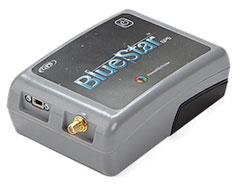
BlueStarGPS offers both GPS and GNSS options in a rugged, lightweight package. The BlueStarGPS device was designed to meet sub-meter mapping and data collection needs in the pipeline and utility industries. It provides sub-meter precision without post-processing, and maintains accurate positioning when the SBAS signal is obstructed. This means it can function under trees, around buildings and in rugged terrain where other receivers can fail.
The BlueStarGPS is designed specifically for use with Android mobile devices, such as smartphones, tablets or notebook computers, as well as cable and pipe “locating” tools with a connectivity range of up to 1 kilometer.
Leica Geosystems has released SiTrack:One, a highly accurate rail track maintenance and refurbishment system incorporating the Leica ScanStation P40 to generate 3D point clouds. SiTrack:One by Leica Geosystems ensures complete coverage of an entire rail infrastructure surface without the need to receive GNSS signals for position information, the company said.
With a new mounting design, the total solution for rail maintenance and refurbishment produces synchronized engineering, survey-grade 3D point clouds for accurate as-built drawings. The Leica ScanStation P40 can either be mounted vertically in the centre of the rails or inverted directly over the rail track. Rail bridge sleeper replacements can be measured quickly generating a numbered as-built replacement plan for each individual sleeper on a rail bridge.
The sophisticated system is equipped with two powerful distance measurement instrument (DMI) or odometers that provide accurate positioning in GNSS-denied areas, such as underground railway tunnels or underground subway networks. The system’s on-site calibration process guarantees permanent alignment of the relative position between the sensors and its onboard inertial measurement unit, guaranteeing position accuracy.
The German engineering firm Vermessungsbüro Riemenschneider GbR was the first to use the SiTrack:One by Leica Geosystems. When converting existing railway tracks in the course of track maintenance for the Deutsche Bahn AG, the firm required complete, accurate and consistent information on existing tracks, clear structure gauge, route topography and civil engineering works. With the SiTrack:One, Vermessungsbüro Riemenschneider GbR experienced significant workflow gains by leveraging the highly accurate point clouds directly into the engineering process.
“The SiTrack:One by Leica Geosystems guaranteed the complete survey of railway sidings with a minimum stay of surveying personnel in the danger zone of rail transport,” said Dipl.-Ing. Andreas Riemenschneider, principal of Vermessungsbüro Riemenschneider. “Thus, the costs of security measures were significantly reduced. The state-of-the-art system conforms efficiently to the demands for survey, visualisation, documentation, evaluation and approval of existing and new routes, all in accordance with rail transportation guidelines.”
Developed from acquired knowledge SiTrack:One is the first solution to be released under Leica Geosystems from the acquisition of the former Technet-Rail 2010 GmbH. Leica Geosystems acquired the previous firm’s specialised knowledge of geospatial big data for rail transportation networks in May to increase its mobile mapping offerings for the rail industry.
“One of our goals in obtaining this specific know-how was to provide users with a dedicated tool for passenger rail networks monitoring and maintenance, and with the development of SiTrack:One, we are taking the first step on this roadmap,” said Stuart Woods, Leica Geosystems Geospatial Solutions Division vice-president. “Professionals can now trust their measurements on rail are accurate even in the most difficult conditions.”
SiTrack:One by Leica Geosystems includes software enabling data synchronization, post-processing and feature extraction. This solution is part of the SiRail Suite, which includes the SiRailScan and SiRailManager software solutions.
SiRailScan allows for a complete extraction of the railway network with engineering accuracy level, while SiRailManager, the database management tool, creates a holistic view of an operator’s railway network from point cloud to geometry and signal layers. The combination of these solutions form the SiControl platform, which conforms to the requirements of the European Train Control System and produces complaint rail xml outputs for full train feedback control.
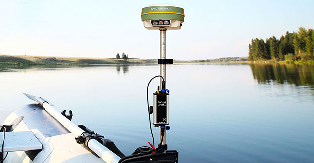
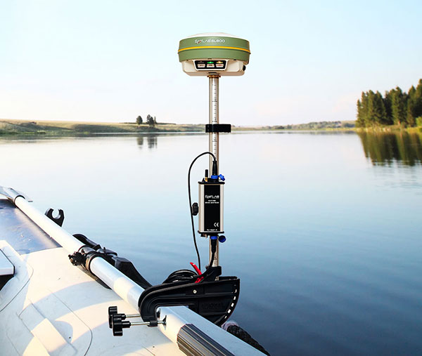
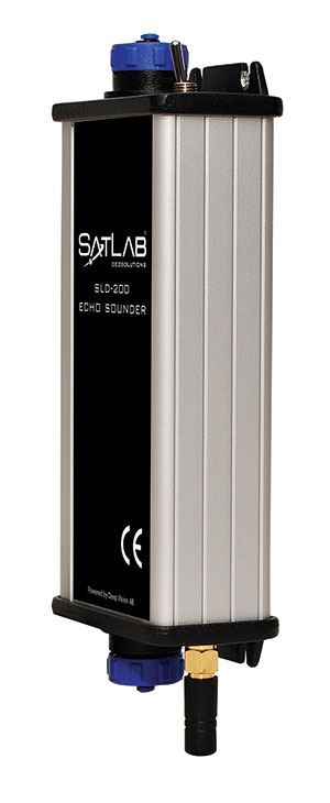
Swedish-based Survey and GIS equipment maker Satlab Geosolutions AB has announced the availability of its SLD-100 GNSS Rover accessory to facilitate Hydrographic measurement in bodies of water up to 100 meters in depth. It is designed for those who find themselves needing to survey into bodies of water, streams and rivers.
With survey-grade accuracy, the Satlab SLD-100 can be added to any brand GNSS RTK Rover to allow for position and depth measurements to be made simultaneously. With a built-in 10-hour lithium battery and transmitter unit with Bluetooth connectivity, the SLD-100 provides standard depth data streams in several industry standard NMEA formats at 1Hz, 4800 bps, providing compatibility with any hydrographic surveying software package.
“Our new SLD-100 survey receiver is extremely easy to use with position and depth information externally logged on a computer or controller,” said Birol Güçlüer”, CTO and partner of Satlab. “With the included transom mounting hardware, installation is quick and easy.”
The SLD-100 is available now for a suggested retail price of US$2995.
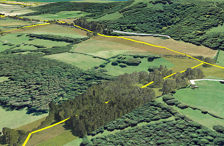
Bluesky has completed a multi-million pound aerial mapping project to assess the impact of vegetation on the electricity network of East Anglia and the South East of England. Working on behalf of UK Power Networks, Bluesky undertook the largest ever combined laser mapping and aerial photography survey commissioned by an electricity distribution network operator in the UK — some 34,000 square kilometers.
The laser mapped (LiDAR) data and aerial photographs were then analyzed to assess the proximity of vegetation to the overhead power lines in order to create a proactive three-year vegetation management program. Bluesky worked in partnership with ADAS, an agricultural and environmental consultancy, to complete the project.
Dedicated survey planes equipped with a lidar mapping system and aerial survey equipment flew the whole of the South East and East of England. Capturing millions of individual laser mapped height measurements and approximately 310,000 aerial images in just over three months, Bluesky successfully completed the unprecedented data capture element of the project within tight project deadlines, in challenging weather conditions and in adherence with strict Air Traffic Control restrictions.
The 80 terabytes of raw data was then processed and analyzed to identify which overhead line spans had vegetation infringement; for example the length of vegetation infestation along each span and its location and distance from the overhead line.
This information has now been incorporated into a 3D web portal that can be viewed from the desktop, enabling UK Power Networks employees to carry out virtual patrols of the network, saving time and reducing the risk of foot patrols, sometimes across difficult terrain including physical barriers such as rivers, ditches, livestock and numerous other potential hazards.
“This innovative £2.5 million project is of immense benefit to our customers and to the company,” said Nigel Hall, head of service development at UK Power Networks. “The risk-based tree-cutting program will help reduce tree-related power cuts for customers, with the additional benefit that it could be carried out without any disturbance to local landowners because it was done from the air rather than on foot.
“As a company it will help us get best value from our £19 million annual tree cutting budget, and the web portal will mean staff can carry out ‘virtual patrols’ from their desk, saving them time and reducing the potential hazards if they had had to walk the lines themselves.”
“Prior to commissioning the LiDAR and aerial mapping project, UK Power Networks undertook regular manual surveys as part of its assessment of network resilience, but the capture of LiDAR and associated aerial photography for the entire catchment area allows for evidence based decision making and long term planning, and provides a proven solution for other network operators,” added Rachel Tidmarsh, managing director of Bluesky.
Roy Dyer, Head of Arboriculture in ADAS and manager of the ADAS contribution to this contract said, “This has been a ground breaking contract. The combination of Bluesky’s technical ability and ADAS’ consultancy experience in managing vegetation near overhead lines enabled us to successfully deliver this challenging contract and improve the management and resilience of the overhead lines owned by UK Power Networks.”
Part 1 of this column appeared in the June Survey Scene newsletter, Part 2 appeared in the August newsletter. Upcoming Survey Scene newsletters will carry additional columns in this series.
Basic Understanding of Scientific and Hybrid Geoid Models
David B. Zilkoski
In my first newsletter column of this series, I discussed the basic concepts of GNSS-derived heights. I discussed the three types of heights involved in determining GNSS-derived orthometric heights: ellipsoid, geoid and orthometric.
In my second column (Part 2), I discussed guidelines for detecting, reducing, and/or eliminating error sources in ellipsoid heights. The column focused on guidelines for establishing accurate ellipsoid heights in a local geodetic network.
This column, Part 3, will describe the differences between a scientific gravimetric geoid model and a hybrid geoid model, and why it is important to use both geoid models in your analysis. The latest published United States National Geodetic Survey (NGS) hybrid geoid model, Geoid12B, is made consistent with the United States National vertical height reference frame, that is the North American Vertical Datum of 1988 (NAVD 88). This means a user will be consistent with NAVD 88 when using GEOID12B to estimate GNSS-derived orthometric heights. However, this doesn’t guarantee that your GNSS-derived orthometric heights are accurate.
NGS’ new Beta experimental geoid height models xGEOID14B and xGEOID15B are not distorted to fit the published NAVD 88 heights so they are useful for identifying valid NAVD 88 bench marks (that is, ensuring the monuments haven’t moved since their last survey and their published heights are still valid). Therefore, it is extremely important to validate all NAVD 88 height constraints used to estimate accurate GNSS-derived orthometric heights. Understanding NGS’ scientific and hybrid geoid models will help the user perform the appropriate analysis to determine which leveling-derived orthometric height constraints should be used as constraints. This newsletter will focus on differences between geoid models in a local project area.
Information on NGS’ experimental geoid models can be found here.
Thursday, August 20, 2015
Yearly Experimental Geoid Model Available for Public Review
In 2022, NGS will replace the current North American Vertical Datum of 1988 with one that is based on the geoid — a model of global mean sea level that is used to measure precise surface elevations. NGS created and released annual experimental models of the geoid starting in 2014. This year’s models, xGEOID15A and xGeoid15, are now available for public comment on the NGS beta website. The annual experimental models include new data from the Gravity for the Redefinition of the American Vertical Datum project, which has systematically collected airborne gravity data across the nation since 2008. For more information, contact: [email protected]
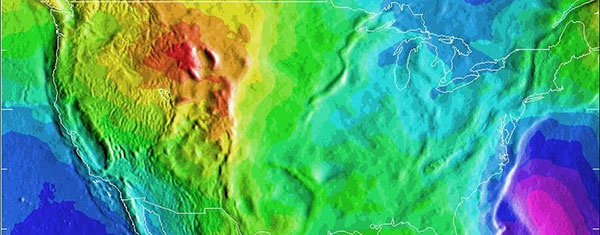
A depiction of the United States geoid. Areas in yellow and orange have a slightly stronger gravity field as a result of the Rocky Mountains.
While we often think of the earth as a sphere, our planet is actually very bumpy and irregular.
The radius at the equator is larger than at the poles due to the long-term effects of the earth’s rotation. And, at a smaller scale, there is topography—mountains have more mass than a valley and thus the pull of gravity is regionally stronger near mountains.
All of these large and small variations to the size, shape, and mass distribution of the earth cause slight variations in the acceleration of gravity (or the “strength” of gravity’s pull). These variations determine the shape of the planet’s liquid environment.
If one were to remove the tides and currents from the ocean, it would settle onto a smoothly undulating shape (rising where gravity is high, sinking where gravity is low).
This irregular shape is called “the geoid,” a surface which defines zero elevation. Using complex math and gravity readings on land, surveyors extend this imaginary line through the continents. This model is used to measure surface elevations with a high degree of accuracy.
How Does the U.S. National Geodetic Survey Generate a Geoid Model?
Generating geoid models is a fairly complex process and is performed by individuals with expertise in physical geodesy and geophysics. It is too complex of a topic for this newsletter but the following excerpt from an NGS publication by Dan Roman provides a good overview of NGS’ process.
Development of the North American Gravimetric Geoid: Adapting the Process to Determine a Unified Central American Geoid
D.R. Roman National Geodetic Survey, 1315 East-West Highway, Silver Spring, MD, USA, 20910
2 Data & Process Improvements
Techniques discussed here have already been addressed previously in Roman and Smith (2001) and Smith et al. (2001), hence only a summary of the approach discussed in those papers is given here. Essentially, the approach currently under investigations seeks to take advantage of recent and pending gains in various data sets related to the gravity field and significantly reduce approximations considered acceptable in the past.
The first thing to consider is the justification for using a geoid over a quasi-geoid, or more accurately, orthometric heights over normal heights. Convincing arguments have been made for orthometric heights (Holdahl 1984) and normal heights (Heiskanen and Moritz 1967). While orthometric heights require extensive knowledge of the gravity field, it is just that reason that warrants their use. Given the extensive knowledge and available data sets, it is incumbent on governmental agencies to generate such models. With a model of the gravity field from the surface to the geoid at hand, anyone subsequently desiring to transform from orthometric to normal heights need only apply it. However, if normal heights are developed and orthometric heights are later desired, the development of such a model will then be required. Clearly, this is a task best suited to national and international organizations that have access to such data and methods. It should not be left to those researchers desiring to use height models in their studies that may not have access to sufficient resources to accomplish this.
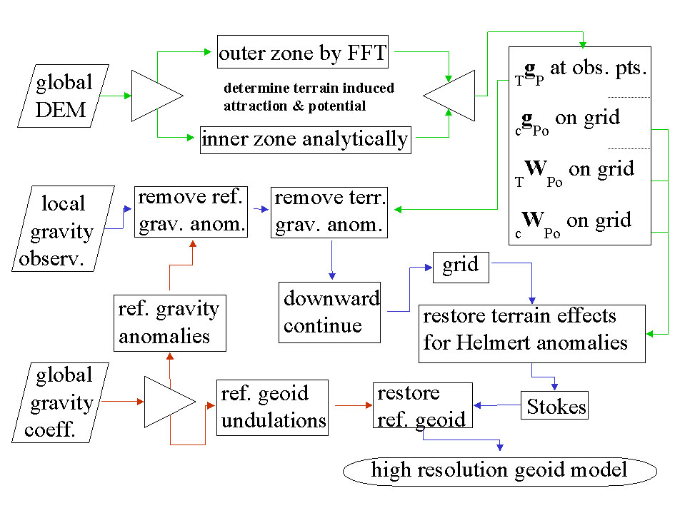
With that understanding then, the development of a gravimetric geoid model follows as a mechanism to readily convert between ellipsoidal and orthometric heights. The method summarized here seeks to break the gravity field into three components and solve them separately. In fact the long wavelength component will be derived from a global reference gravity model. The short wavelength will be determined from the terrain. Both of these components will be removed from available gravity observations, which will then reflect the intermediate wavelength signal. A flowchart depicting the determination of these three signals and the generation of a gravimetric geoid is given in Figure 1. Paths shown in red highlight the use of the reference model, paths in green show the determination of the terrain effects, while paths shown in purple highlight the main path to determining Helmert anomalies and then a gravimetric geoid model.
Fig. 1 Determination of a gravimetric geoid using Helmert anomalies.
The expected accuracy of global gravity models in the near future is expected to vastly improve with commission errors below 1-2 cm at wavelengths of 200-300 km (Tscherning et al. 2000). Use of a remove and restore technique (Bašiæ and Rapp 1992) will then result in significantly reduced errors in the residual signal that will be manipulated.
The approach discussed in Roman and Smith (2001) develops the North American gravimetric geoid by removing the terrain effects, downward continuing the residual values, and then restoring the effects of the condensed terrain to generate Helmert anomalies (Heiskanen and Moritz 1967).
To this end, the gravitational attraction of the terrain (TgP) will be calculated and removed from the gravity observations. It will be split into inner and outer zones to reduce computation times. Smith et al. (2001) showed that the effects of using FFT to determine gravitational attraction and potential for both condensed and 3D masses is negligible beyond about a 4 degree cap radius from the point of interest (P). Inside that zone, DEM’s are employed to capture the spherical relationships between the points and more accurately determine the attraction. With available or pending 1 and 3 arc-second DEM’s (Smith and Roman 2001a, NIMA 2001), the signal that may be determined is limited mainly by the computational facilities available to a researcher.
Additionally, the DEM’s will be used to construct grids for the attraction and potential of the condensed terrain (cgPo and cWPo), as well as the potential of the actual terrain (TWPo), all on the geoid. This will capture the short wavelength gravity signal represented by the terrain to the resolution of the grid generated and facilitate later incorporation of this signal into Helmert anomalies.
The resulting point values should be composed mainly of intermediate features in the gravity field with sources deriving from variations in the Moho depth and lateral density variations. This signal should be sufficiently smooth to reduce errors resulting from downward continuation. It should also sufficiently sample the intermediate field to permit the use of minimum curvature (Smith and Wessel 1990) to generate a grid at the same interval as that of the above terrain effects.
Once these terrain effects are restored, these extremely high resolution grids represent residual Helmert anomalies and may be processed using the Stokes integral to determine a best fitting residual gravimetric geoid. Adding the reference geoid derived from the selected global coefficient model will create an equally high-resolution regional gravimetric geoid model.
For a specific country, GPS-derived ellipsoid heights at leveled bench marks (GPSBM’s) provide control information for generating a hybrid geoid model that can be used to specifically, easily, and accurately transform heights between ellipsoidal and orthometric heights (Smith and Milbert 1999, Smith and Roman 2001b).
What are Hybrid Geoid Models and how are they Generated?
NGS’ hybrid geoid model GEOID12B is computed based on the gravimetric geoid USGG2012. As described above, the gravimetric geoid is computed using the satellite model (GOCO3S), terrestrial gravity data, and the altimetric gravity anomaly over oceans. The heights of USGG2012 represent an equipotential surface relative to the reference ellipsoid. The differences between USGG2012 and the zero height surface of NAVD88 are represented by NAD 83 (2011) GNSS-derived ellipsoid heights on NAVD 88 published benchmarks (GPSBM data). See article by Milbert, D.G., 1998: “Documentation for the GPS Benchmark Data Set of 23-July-98,” IGeS Bulletin N. 8, International Geoid Service, Milan, pp. 29-42.) for a excellent description of NGS’ GPSBM dataset.
Currently, the USGG2012 is fitted to the GPSBM data by using the method of least squares collocation. (See section labeled “Excerpts from NGS’ Geoid 12 Web Page” for specific details on how NGS generated hybrid geoid model GEOID12B.) Areas where there are no GNSS observations on published NAVD 88 benchmarks are filled in by USGG2012 geoid. This means a user will be consistent with NAVD 88 when using GEOID12B to estimate GNSS-derived orthometric heights. Being consistent with NAVD 88 is important but being consistent doesn’t guarantee that your GNSS-derived orthometric heights are accurate. The documentation of GEOID12B states that “The relative accuracy of GEOID12B to NAVD88 is characterized by a misfit of +/-1.7 centimeters nationwide.” However, if a published NAVD 88 height used in the development of the hybrid geoid model isn’t valid, then the model is precise but not accurate. That’s why it is important to ensure the monuments used in hybrid geoid models haven’t moved since their last survey and that their published heights are still valid. We will discuss this in more detail later in this newsletter.
Hybrid geoid model, GEOID12B is computed based on the gravimetric geoid USGG2012 . More specifically, they are computed using the satellite model GOCO3S, terrestrial gravity data, and the altimetric gravity anomaly over oceans. The heights of USGG2012 represent an equipotential surface relative to the reference ellipsoid. The differences between USGG2012 and the zero height surface of NAVD88 are represented by GPSBM data.
Currently, the USGG2012 is fitted to the GPSBM data by using the method of least squares collocation. That implies that the voids or empty areas where there are no GPSBM data are filled in by USGG2012 geoid.
There are over 500,000 leveled marks and 80,000 GPS marks over U.S. territory. Of those, there are only 26,000 GPSBM, with half of them concentrated in 5 states. The data density is uneven and sparse in some states. Lists of GPSBMs can be downloaded from the GEOID12B home page.
The GPSBM data provide the geoid height ‘N’ by differencing the ellipsoidal height ‘h’ from the orthometric height ‘H’:
N = h – H
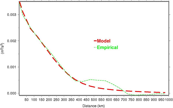
The difference between the geoid height N and that of USGG2012 is computed at every GPSBM. Then, a mathematical model using Least Squares Collocation (LSC) fitting Gaussian functions to describe the behavior seen at the GPSBM is developed. Figure 1 shows empirical data versus the model.
Figure 1: Covariance functions of the geoid differences between USGG2012 and GPSBMs.
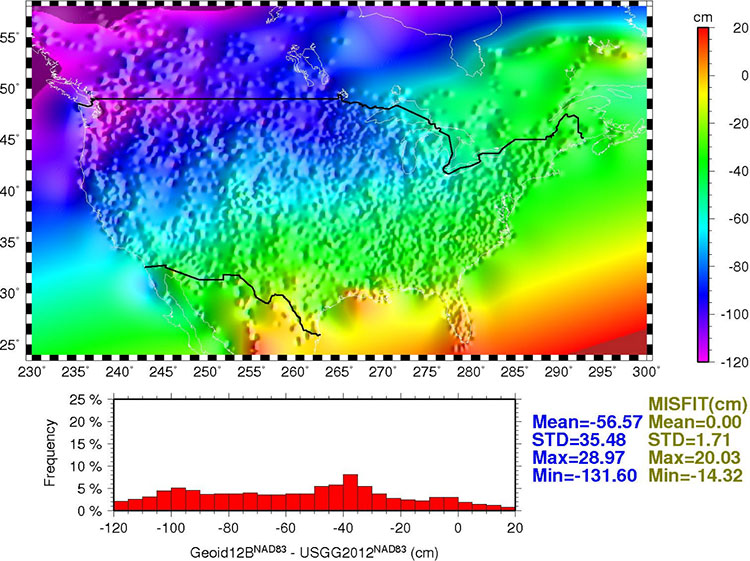
Once the relationship between the points is modeled, the model is used to generate a regular grid for interpolation purposes. Figure 2 shows the final conversion surface. This surface represents the difference between NAVD 88 as a datum and the geopotential (geoid) surface used in the gravimetric geoid and is representative of what the datum transformation surface will be when the new geopotential datum is released in 2022. (Similar to VERTCON, which transforms heights from NGVD29 to NAVD88.)
Figure 2: GEOID12B conversion surface.
Summary and Recommendations
Three hybrid geoid models GEOID12, GEOID12A, and GEOID12B are created. They are very similar, but have distinctive differences in few areas. GEOID12A differs from GEOID12 in that it does not use GPSBM data collected in the southern tier states along Gulf Coast, while GEOID12B differs from GEOID12A only in Puerto Rico.
Data in the database are constantly updated, hence older geoid models do not reflect the newer data. To guarantee data consistency, latest model should be used. At this time, GEOID12 and GEOID12A should be superseded by GEOID12B.
Use data conversion outside the GPSBM data areas with caution. Significant extrapolation errors are expected in areas where there are no GPSBM data.
The relative accuracy of GEOID12B to NAVD88 is characterized by a misfit of +/-1.7 centimeters nationwide.
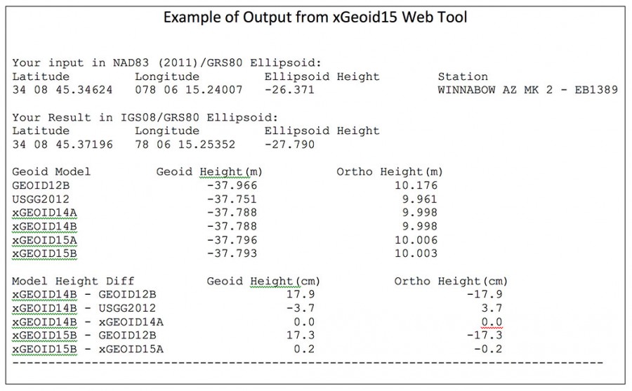
As previously stated, NGS released its latest gravimetric geoid model, xGEOID15. This site will allow the user to compare geoid heights from GEOID12B, USGG2012, xGEOID14 and xGEOID15. (See an example of an input and an output file below.) There are some limited features to this tool. It only provides the results in IGS08 and you are limited to the number of coordinates you can submit at once (20 stations).
Saying that, this tool can be useful for identifying valid NAVD 88 published monuments to be used in the development of future hybrid models. More importantly, it can be used to identify monuments that should NOT be used in future hybrid geoid models or used as constraints in GNSS survey project adjustments.
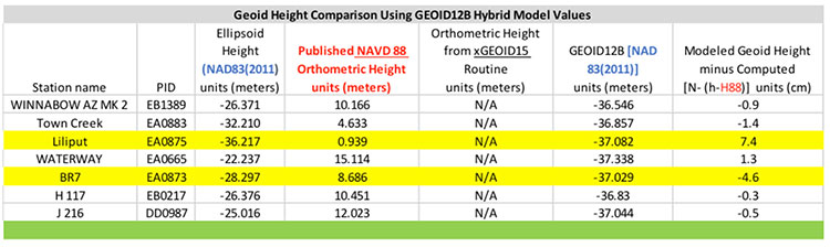
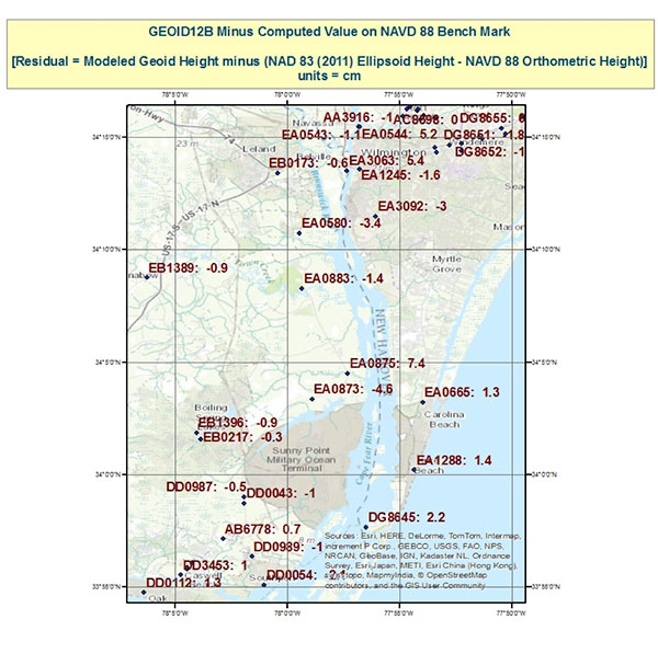
First, let’s look at the hybrid geoid model GEOID12B values compared with computed geoid height values using the equation N (Computed Geoid Height) = [h (NAD 83 (2011) Ellipsoid Height) – H (NAVD 88 Orthometric Height)]. Table 1 lists the differences between the modeled GEOID12B values and the computed geoid height values for a few stations in an area in eastern North Carolina. Figure 1 depicts the stations locations and values. Many of the differences are less than 1.5 cm which is consistent with NGS’ documentation of GEOID12B that states “The relative accuracy of GEOID12B to NAVD88 is characterized by a misfit of +/-1.7 centimeters nationwide.” However, what is important to notice is that two stations have large differences; station LILIPUT’s difference is 7.4 cm and station BR 7’s difference is -4.6 cm (See highlighted rows in table 1 and boxed area on figure 1). This means that the relative difference between stations LILIPUT (EA0875) and BR 7 (EA0873), which are only 3.3 km apart, is 12.0 cm. This is a large difference and may be indicating a large error in the ellipsoid height and/or the orthometric height at station LILIPUT (EA0875) or station BR 7 (EA0873). In the second newsletter we highlighted that stations LILIPUT and BR 7 were only 3.3 km apart but were not simultaneously observed during the same session. Since the relative difference is 12 cm, the ellipsoid heights of these two should be investigated. It should also be noted that the difference between stations BR 7 (EA0873) and TOWN CREEK (EA0883) is only 3.2 cm. This implies that station B 7 (EA0873) is consistent with some of its neighbors. In the second newsletter we noted that stations B 7 (EA0873) and TOWN CREEK (EA0883) were simultaneously observed during the same session. This may be an indication that B 7 is stable relative to its neighbors and that the orthometric and/or the ellipsoid height of station LILIPUT needs to be investigated.
So what does this mean to the user? If the user establishes a GNSS-derived orthometric height near station LILIPUT using GEOID12B, their results will disagree with the published NAVD 88 heights to around 7 cm; if they establish a GNSS-derived orthometric height near station BR 7, they will disagree with published NAVD 88 heights to around –5 cm. This could also mean that the results in a project could really disagree by more than 7 cm if station LILIPUT moved since its last survey. At this moment, we don’t have enough information to determine if the ellipsoid height or the orthometric height is the problem, or which station may have moved since its last survey.
Table 1. Geoid Height Comparison using GEOID12B Hybrid Model Values.Figure 1. Geoid12B minus Computed Value on NAVD 88 Benchmarks.
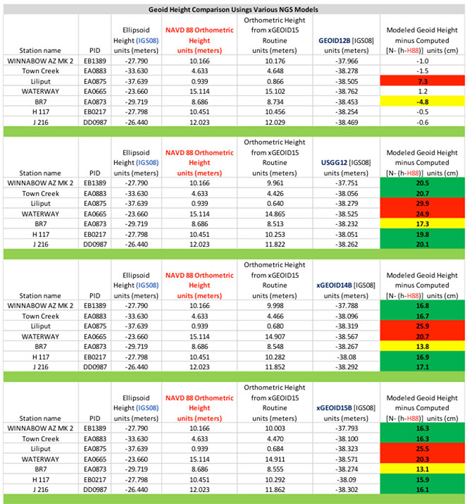
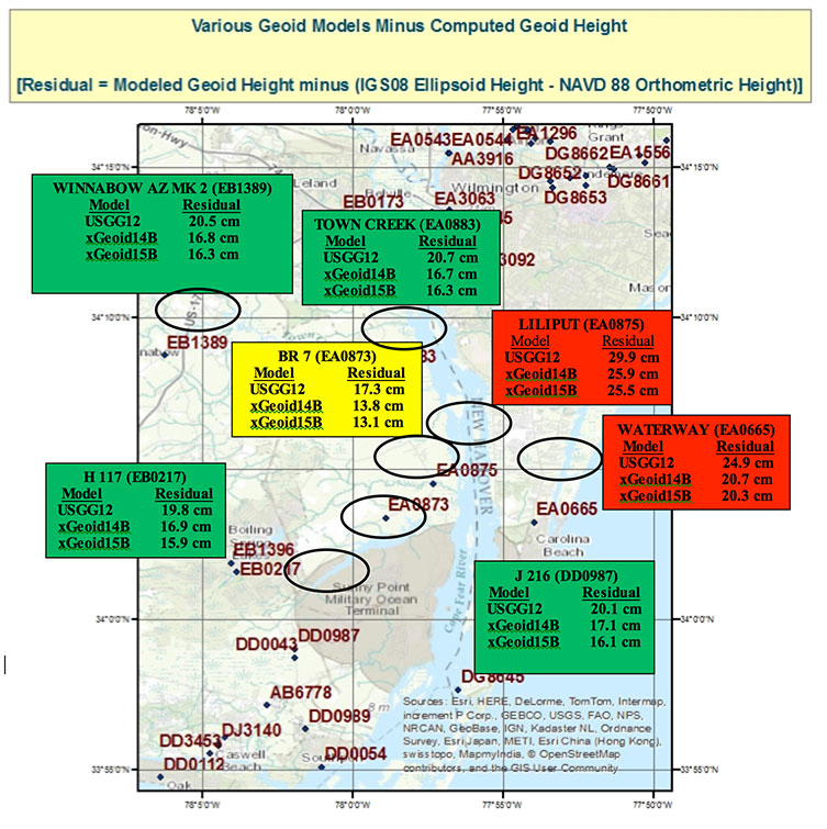
Next, let’s look at the differences using the experimental geoid models which are not distorted to be consistent with the NAVD 88 published heights. There will be a bias and a tilt between the systems but in this small areal extent the tilt should not be significant to our analysis. The bias can be removed by looking at relative differences between stations. Table 2, titled “Geoid Height Values for Various NGS Models using xGeoid15 Web Tool,” provides the modeled geoid height minus the computed geoid height where N (Computed Geoid Height) = [h (IGS08 Ellipsoid Height) – H (NAVD 88 Orthometric Height)]. Figure 2, titled “Various Geoid Models minus Computed Geoid Height,” depicts the differences between the various experimental models and computed geoid heights.
Table 2. Geoid Height Values for Various NGS Models using xGeoid15 Web Tool.Figure 2. Various Geoid Models minus Computed Geoid Height.
What is important to note is that stations LILIPUT (EA0875) and WATERWAY (EA0665) seem to be outliers compared to the other stations in the area of study (red boxes on figure 2); and station B 7 (EA0873) seems to be consistent with its neighbors (yellow box on figure 2). For example, station LILIPUT (EA0875)’s residual using xGeoid15B is 25.5 cm and station BR 7 (EA0873)’s residual using xGeoid15B is 13.1 cm, a relative difference of 12.4 cm. Similarly, station TOWN CREEK (EA0883)’s residual using xGeoid15B is 16.3 cm and station BR 7’s residual is 13.1 cm, a relative difference of only 3.2 cm. In my opinion, station LILIPUT (EA0875) needs to be investigated to determine if it has moved since it was last surveyed. In addition, stations east of LILIPUT (EA0875) such as WATERWAY (EA0665) should also be investigated for an ellipsoid and/or orthometric height issue. As previously mentioned, it is also important to note that station BR7 (EA0873), the box in yellow, appears to be consistent to the 3 cm level with its westerly neighboring stations (the boxes in green). This is important to note because the hybrid geoid model could be significantly difference around stations LILIPUT and BR 7 if station LILIPUT was not used in the development of the hybrid geoid model. I am not suggesting that NGS did anything incorrect by including these stations. The goal of the hybrid geoid model is to be consistent with published NAVD 88 values. Unless there is enough information to determine that a station has moved since the last time it was surveyed, the station should be included in the hybrid model. This is where the user may be able to help NGS. If users would investigate outliers like LILIPUT and BR 7 and provide new GNSS survey data and/or leveling data, NGS may have the appropriate information to determine if the monument should be included in the hybrid model.
Part 2 in this Survey Scene series discussed procedures which need to be followed to detect, reduce, and/or eliminate error sources to estimate accurate GNSS-derived ellipsoid heights. This column, Part 3, discussed why a user should understand the differences between NGS’ scientific gravimetric geoid model and hybrid geoid models, and why it is important to use both types of geoid models in their analysis. It demonstrated how to use these geoid models and ellipsoid heights to identify potential issues with published NAVD 88 heights.
My next newsletter column will focus on analyzing the NAVD88 orthometric heights in this area. It will provide basic procedures for validating NAVD 88 height constraints used to estimate GNSS-derived orthometric heights.
A new fourth edition of GPS Satellite and Surveying, by Leick, Rapoport and Tatarnikov, is available through NavtechGPS.
GPS Satellite and Surveying is a comprehensive guide on GPS technology for surveying. Three prior editions have established it as a definitive industry reference.
Updated and expanded to reflect the newest developments in the field, the fourth edition features cutting-edge information on GNSS antennas, precise point positioning, real-time relative positioning, lattice reduction and more. The authors — Alfred Leick, Lev Rapoport and Dmitry Tatarnikov — examine additional tools and applications, offering complete coverage of geodetic surveying using satellite technologies.
Nikon-Trimble Co., Ltd. introduced today updated mechanical total stations to expand its portfolio of solutions for mainstream surveying and construction applications.
The announcement was made at INTERGEO 2015, the world’s largest conference on geodesy, geoinformatics and land management.
The updated products include:
Nikon NPL-322+ Series – an updated series of reflectorless 2” and 5” total stations providing powerful solutions and an excellent choice for value in terms of price and performance. The NPL-322+ Series feature a distance measurement accuracy of up to ±(2 + 2 ppm x D) mm and provide a long-distance reflectorless measurement range of 400 meters (1,312 feet.). The Nikon NPL-322+ Series also include a coaxial laser pointer, Bluetooth connection to external data collectors, onboard storage for 25,000 points and dual-axis compensation for significantly faster measurement times.
Nikon DTM-322+ Series – an enhanced series of economic, prism-based 2” and 5” total stations offering full featured functionality in an entry-level package. The DTM-322+ Series offer a distance measurement accuracy of up to ±(3 + 2 ppm x D) mm and a measurement range of 2,300 meters (7,540 feet.) to a prism. In addition, the Nikon DTM-322+ Series include a Bluetooth connection to external data collectors, onboard storage for 25,000 points, dual-axis compensation and new, long-lasting Li-Ion batteries.
“The Nikon optical portfolio continues to evolve to meet the ever changing needs of our customers who truly appreciate the reliability and dependability represented by the Nikon name,” said Olivier Casabianca, Spectra Precision Business Area Director. “Our customers enjoy the benefits of a mature, robust portfolio of survey and construction products from a single supplier they can trust.”
Spectra Precision introduced at INTERGEO this week new and enhanced products in its portfolio of survey solutions. With the new additions, survey and construction professionals have more positioning instrument choices to meet their job requirements, the company said.
Spectra Precision made the announcement at INTERGEO 2015, the world’s largest conference on geodesy, geoinformatics and land management.
The new and enhanced products include:
Spectra Precision FOCUS 35 RX – A new range of motorized total stations providing high-speed, accuracy and precision in measurement. The FOCUS 35 RX robotic instrument moves the power of the observer from the instrument to the range pole, improving efficiency. The speed of observation and precise positioning of the FOCUS 35 RX Robotic Total Station is provided by patented StepDrive motion technology, which controls the horizontal and vertical motion of the motors, eliminating the need for traditional motion locks. The FOCUS 35 RX includes a tracking sensor that uses LockNGo FastTrack tracking technology, enabling the instrument to constantly lock onto the prism.
The FOCUS 35 RX is available in 2”, 3” or 5” accuracies, features market leading extended operating time with its dual battery system and is controlled externally by Spectra Precision Ranger, Nomad, or T41 data collectors running Spectra Precision Survey Pro or Spectra Precision Layout Pro field software on the Ranger or Nomad.
“The streamlined design, extremely light weight, very quick turning speed and exceptional battery life enhance the overall value-proposition of the FOCUS 35 RX and make this instrument a very compelling choice for a wide range of survey and construction applications,” said Olivier Casabianca, Spectra Precision Business Area Director. “With the introduction of the FOCUS 35 RX, Spectra Precision continues to expand and improve its portfolio with powerful solutions using new technologies.”
Spectra Precision Nomad 1050 Data Collector — The Nomad 900 has been updated with new features and capabilities. The Nomad 1050 has more RAM, more Flash and more speed. The base processor is now 1 GHz compared to 806 MHz on Nomad 900 and the Nomad 1050 has 512-MB RAM and 8GB flash storage. The other major enhancement is a new 3.75-G dual-mode GSM and CDMA WWAN modem to provide fast and versatile connectivity for Spectra Precision customers. Also, the new WWAN module uses an internal antenna eliminating the need for an external antenna.
Spectra Precision Survey Pro 5.7 Field Software — Constant improvement and enhancement continues with Survey Pro. Survey Pro version 5.7 contains significant changes to enable more productive field data collection. Included in this update are new map displays that enable viewing and managing most of the map features that are located on the main map display. The GNSS and robotic staking screens can also display a map view to include background maps along with the standard dynamic guidance control option. The GNSS offsets routine has been updated and now includes a distance-distance option. For those customers who wish to use GNSS and robotic simultaneously, there are now enhanced options for configuration and switching between modes.
Spectra Precision Survey Office v3.60 Software — Spectra Precision Survey Office now includes enhanced functionality; support for the Spectra Precision FOCUS DL-15 Digital Level and the import of leveling data from any DiNi level; least squares and 5 and 7 parameter Helmert transformations with reports; Geoid 12B support and grouping by country in the Coordinate System Manager; Point Cloud support plus many more additional enhancements.
Spectra Precision MobileMapper Field GIS Application for Android Devices — A new version of the popular MobileMapper Field GIS application now running on Android devices. This new software is dedicated to GIS data collection and focuses on simplicity to maximize the number of field personnel contributing to the geospatial business. Primarily for MobileMapper 300 users, the application will be the key component of Spectra Precision’s Bring Your Own Device (BYOD) solution. This makes it possible to pair Android tablets and/or smart phones with the MobileMapper 300 GNSS receiver to collect GIS data with survey-grade accuracy.
“With the introduction of these new and enhanced products into the Spectra Precision portfolio, survey and construction professionals have a wider range of economical choices to get the job done,” said Olivier Casabianca. “These new Spectra Precision optical products complement the ground-breaking line of Spectra Precision solutions, enabling Spectra Precision to offer a complete range of survey products.”
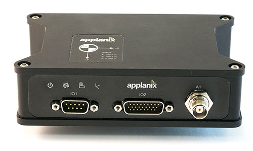
Applanix Corporation has announced the POS AVX 210, the latest addition to its airborne position and orientation portfolio for direct georeferencing of airborne mapping sensors. Using Applanix’ GNSS and inertial technology, the POS AVX 210 enables airborne surveyors to achieve gains in accuracy, efficiency and productivity for low-altitude or small form factor sensors, when compared to GNSS-only point-matching or aerial triangulation techniques.
The announcement was made at the INTERGEO 2015 conference and exhibition in Stuttgart, where Applanix is exhibiting in Hall 8, Booth C8.047.
For photogrammetric applications, the POS AVX 210 delivers highly accurate exterior orientation solutions — reducing the requirement for ground control in assisted aerial triangulation of digital single lens reflex (DSLR) or medium-format photogrammetric imagery. For low-altitude lidar applications, the POS AVX 210 provides the required precision and accuracy of direct georeferencing to enable users to generate point clouds for further refinement in adjustment software.
The POS AVX 210 is fully compatible with, and supported by, POSPac MMS, Applanix’ post-mission software for direct georeferencing of airborne mapping sensors. It is also features a seamless integration with the NanoTrack system from Track’Air, a leading commercial flight management system designed for highly efficient survey flight operations. Aircraft equipped with the POS AVX 210 and NanoTrack will be able to fly missions with reduced sidelap between flightlines, and a greatly reduced requirement for ground control points. These benefits can reduce costs and improve the efficiency of both data collection and the production of finished data sets for end users.
“With POS AVX 210, Applanix has answered a need in the marketplace for a small, compact system that enables efficient data gathering from low-cost yet highly effective sensors. These include DSLR and Medium format cameras, low-altitude lidar systems, and other systems,” said Joe Hutton, director of Inertial Technology and Airborne Products at Applanix.
POS AVX 210 consists of a single rugged enclosure containing a precision GNSS receiver and micro-electro-mechanical-system (MEMS) inertial sensors calibrated with the Applanix SmartCal technology, coupled with on-board data logging capability and interfaces for mapping sensors and flight management systems. POSPac MMS, available as an option with POS AVX 210, is a powerful GNSS-inertial processing software package that includes proprietary advanced capabilities such as the Applanix SmartBase virtual reference station, Applanix InFusion algorithms for increased productivity, and CalQC, a suite of data optimization and quality management tools.
“POS AVX 210 builds on the technological foundation of our established POS AV portfolio for large format sensors, and brings into play the innovations developed for our unmanned solutions. This combination of experience and innovation enables us to deliver a package that strikes the optimal balance between price and performance for this segment,” Hutton said.
POS AVX 210 is expected to be available in the first quarter of 2016 through Applanix’ airborne sales channels.
Trimble debuted its new R2 GNSS receiver at Intergeo 2015, held this week in Stuttgart, Germany.
The R2 GNSS receiver is a receiver that works with Trimble handheld devices and iOS, Android or Window mobile handhelds, smartphones and tablets using Bluetooth or USB connectivity. When paired with a mobile device, the receiver adds professional-grade GNSS capabilities for better accuracy. The rugged Trimble R2 provides GIS and survey professionals the flexibility to choose the mobile device, workflows and accuracy they need based on applications.
Trimble R2 GNSS Receiver for Mobile Devices
The Trimble R2 GNSS receiver is compact and portable, weighing 2.4 pounds. With one-button operation and a field swappable battery, the receiver can be pole or vehicle mounted or carried on a backpack. The R2 is a multi-constellation receiver that supports GPS, GLONASS, Galileo, BeiDou and QZSS satellite signals, as well as SBAS.
With a variety of standard and optional correction capabilities, the Trimble R2 can achieve sub-meter to centimeter positioning for a broad range of accuracy requirements. The receiver is an option for the Bring Your Own Device (BYOD) strategy.
“Today’s geospatial professionals require flexible solutions which allow for configuration to meet their specific job requirements,” said Ron Bisio, general manager of Trimble’s Surveying and Geospatial Division. “The Trimble R2’s versatility to support GIS and survey workflows as well as BYOD deployment enables geospatial professionals to collect data using the mobile device, workflow and accuracy they choose.”
Workflows – GIS and Survey Field Software
Designed for both GIS field data collection and survey workflows, the Trimble R2 receiver integrates with Trimble TerraFlex mapping and GIS field software and Trimble Access survey field software.
TerraFlex software is a scalable cloud-based solution for geospatial data collection. By pairing the R2 with a smart device or Trimble handheld running TerraFlex, the solution addresses a wide variety of field requirements, including attribute-rich GIS data collection on consumer and professional devices.
Trimble Access software supports the workflows of everyday surveying tasks such as topographic and control surveys and specialized surveying tasks such as roads, monitoring, tunnels and mines. By pairing the receiver with a Trimble handheld running Trimble Access or TerraFlex field software, the Trimble R2 is a versatile solution that supports the full range of geospatial data collection workflows for both GIS and survey applications.
Flexible Accuracy
The receiver is capable of receiving a broad range of corrections from traditional RTK, VRS networks and SBAS to Trimble RTX correction services via cellular/IP connections or satellite (L-band), the Trimble R2 provides high-accuracy data worldwide.
The R2 GNSS receiver can leverage the entire portfolio of subscription-based Trimble RTX correction services to accommodate a wide range of applications and accuracy requirements. This includes CenterPoint RTX (less than 4 centimeters), RangePoint RTX (less than 50 centimeters), and ViewPoint RTX (less than 1 meter) correction services.
The Association for Unmanned Vehicle Systems International (AUVSI) today released a report that finds more than 25 types of business operations have been approved by the Federal Aviation Administration (FAA) to fly unmanned aircraft systems commercially in the National Airspace System (NAS). According to the report, aerial photography received the most exemptions followed by real estate and aerial surveying. The report also finds that exemptions have been approved in 49 states.
“These figures show that businesses across every industry sector have been waiting to use UAS for years and are excited to finally get this technology off the ground,” said Brian Wynne, president and CEO of AUVSI. “From inspecting bridges and power lines to filming movies and supporting emergency services, the applications of UAS are virtually limitless and enable researchers, public agencies and businesses to do things that were previously considered to be impossible.”
In May 2014, the FAA announced it would consider granting exemptions for certain low-risk commercial UAS applications under Section 333 of the FAA Modernization and Reform Act of 2012. Since then, the agency has received more than 2,700 requests and approved more than 1,400 petitions.
AUVSI analyzed the first 1,000 exemptions approved by the FAA. Specifically, the report finds:
The approved exemptions cover more than 25 types of business operations, with aerial photography receiving the most approvals with 512. Real estate followed with 350 exemptions and general aerial surveying with 301 exemptions.
Exemptions were approved for operators from 49 states. California received the most with 114, followed by Florida with 97 and Texas with 82.
California companies also manufactured the most platforms mentioned in the approvals, totaling 140. Florida followed with 19. In all, 22 states house manufacturers of platforms approved in the first 1,000 exemptions.
More than 90 percent of the first 1,000 exemptions were granted to small businesses.
Companies that received exemptions generate at least $500 billion to the U.S. economy annually and represent more than 600,000 jobs.
While the Section 333 process has continued to unlock the potential of UAS technology, AUVSI emphasized that regulating by exemption is no substitute for finalized rules.
“For the full potential of the UAS commercial market to be realized in the U.S., the FAA needs to finalize its small UAS rule as quickly as possible,” Wynne said. “Once this happens, we will have an established framework for UAS operations allowing anyone who follows the rule to fly. The positive effects of the regulation will be felt across the whole country.”
An economic impact study released by AUVSI in 2013 found the UAS industry will create more than 100,000 new jobs and more than $82 billion in economic impact within the first ten years following UAS integration.
The complete study, including state-by-state data, is available.
The latest solutions by Teledyne Optech for the productive and accurate collection of spatial data will be on display at INTERGEO 2015, taking place Sept. 15-17 in Stuttgart, Germany — including a new solution for survey-grade mobile mapping.
At booth C4.019 in Hall 4, Teledyne Optech will present the latest addition to its high-powered Optech Lynx mobile survey systems. The new model is designed for both efficient asset collection and the delivery of engineering survey-grade results, giving operators flexibility for multiple types of jobs. Teledyne Optech will also demonstrate how the advanced features of Optech LMS 3.0 improve collection and processing efficiency by enabling access to survey control.
Several other Teledyne Optech systems will be at the booth, including the Optech Galaxy airborne mapper. Visitors can take the opportunity to see how Galaxy vastly improves survey efficiency and consistency in variable terrain by letting surveyors ignore multipulse blind zones and keep their swath and point density on the ground constant with its PulseTRAK and SwathTRAK technologies. Forestry and coastal data from the Optech Titan will also be available, with Teledyne Optech experts ready to explain the new techniques that surveyors, government agencies and academics have developed to take advantage of its revolutionary multispectral lidar technology for topo/bathy surveys, land classification and biomass estimation.
The CZMIL Nova System is designed for airborne coastal and marine mapping.
Groups interested in surveying deeper in turbid waters than any other airborne lidar can also drop by the booth to hear more about the Optech CZMIL Nova. Even smaller organizations with limited budgets can now make use of CZMIL Nova, thanks to redesigned hardware that lets it survey from aircraft as small as a Piper Navajo, plus the ability to rent the sensor and its HydroFusion workflow through the CZMIL Project Program.
For smaller scale projects, Teledyne Optech will display integrated solutions using the flexible Optech ILRIS terrestrial lidar scanner: Users can rapidly survey open pit mines by combining ILRIS with photogrammetry from the new geo-XR6 UAV, constantly monitor dangerous areas for landslides with the Gexcel OPMMS solution, or even survey harbors above and below water simultaneously with an integrated ILRIS/Seabat sonar system.
Visitors interested in improving productivity and safety in underground mining can see the Optech Cavity Monitoring System (CMS) V500 in action and try out its new integrated camera, georeferencing tools and more.
 BlueStarGPS offers both GPS and GNSS options in a rugged, lightweight package. The BlueStarGPS device was designed to meet sub-meter mapping and data collection needs in the pipeline and utility industries. It provides sub-meter precision without post-processing, and maintains accurate positioning when the SBAS signal is obstructed. This means it can function under trees, around buildings and in rugged terrain where other receivers can fail.