The University of Colorado – Denver has received a significant gift from Trimble to establish a state-of-the-art technology lab for the College of Engineering, Design and Computing.
The gift will also support the departments or programs in construction engineering and construction management, geography and environmental sciences, physics, and urban and regional planning. The lab will expand the university’s access and expertise in a customized suite of construction hardware and software products.
Trimble’s broad Connected Construction portfolio enables professionals along the project lifecycle to accelerate project processes — improving productivity, quality, transparency, safety and sustainability, while reducing waste.
The Trimble Technology Lab will provide students enrolled across relevant programs hands-on experience with a wide breadth of Trimble solutions. The lab will expand the university’s access and expertise in project management, architectural and structural analysis, design and engineering, mixed reality, 3D scanning, office-to-field solutions, and GIS data collection and GNSS positioning.
Partnering with Trimble allows the University of Colorado – Denver to integrate the latest technology into its curricula, empowering graduates to rapidly transform how buildings and living environments are designed and constructed.
The lab will include a broad range of Trimble’s technologies.
Hardware includes the Trimble XR10 HoloLens with hardhat, TX8 3D laser scanner, Trimble SiteVision AR system, R12 GNSS systems, Juno 5D handheld scanner, Geo 7x mobile GNSS data collectors, robotic total stations and field tablets.
Software solutions include RealWorks scanning software, Trimble Business Center, Tekla Structures, Tekla Structural Designer, Tekla Tedds, Trimble Connect, ProjectSight, Viewpoint, TILOS, Trimble Positions Desktop, TerraSync and TerraFlex, eCognition, and the company’s 3D modeling software, SketchUp Pro.
“CU Denver is right in our backyard, providing an exciting opportunity to integrate our industry-leading technologies into a wide range of educational programs. Their proximity enables us to work closely while ensuring easy access, training and support, and success in all aspects of implementation,” said Allyson McDuffie, director of Education & Outreach at Trimble. “Trimble’s education and outreach programs aim to support the next generation of influencers by actively working with key education institutions to ensure Trimble’s portfolio of solutions are accessible and implemented in higher education curricula and research programs, creating a new workforce equipped and empowered to ‘Transform the Way the World Works.’”
Martin Dunn, dean of the College of Engineering, Design and Computing, said, “I am thrilled with and grateful for this exciting relationship with Trimble. It will accelerate our strategic vision to educate diverse graduates who will not only make an immediate impact in the AEC industry, but will emerge as its future leaders. The generous gift will have broad impact across our campus, nucleating the kind of interdisciplinary collaboration among engineers, architects, construction managers, and scientists that is needed to create and exploit technological innovation to address grand challenges facing the built environment including digital transformation, sustainability, and the future of work and the workforce.”
“Our students and faculty could not be more excited to have access to Trimble technologies. Trimble is a company of international importance, which is also right down the road from our campus. In establishing this new lab, our students will be exposed, either virtually or on-site, to cutting edge products and innovation as well as benefit from direct access to the many professionals in Trimble’s worldwide network. Trimble is exactly the type of company that gets our students excited about pursuing careers in construction and engineering,” said Caroline Clevenger, associate professor and director of Construction Engineering and Management.
The Caribbean Division of The Nature Conservancy (TNC) has focused on monitoring, protecting and restoring the region’s marine environments for more than 40 years. As the plight of coral reefs has become more urgent, so too have TNC’s efforts to tackle coral conservation, and meet the demands for better maps.
“Reef maps are an essential tool for coral resource managers, but historically these maps have had insufficient detail, been outdated or been produced for small areas,” said Steve Schill, TNC marine conservation specialist. “Not having access to accurate, large-area reef maps has limited our understanding of these ecosystems and the benefits they provide.”
Having used Trimble’s eCognition object-based image analysis (OBIA) software for automatically classifying and mapping small reef areas, Schill believed eCognition could be the enabling, scalable approach to map the hundreds of thousands of reefs across the region.
Schill worked with technical professionals at Earth observation company Planet and researchers at Arizona State University to select 30,000 4-meter-resolution scenes from the Dove satellite constellation. The team then created a seamless mosaic of the whole Caribbean basin. He also partnered with eCognition specialists Tama Group to develop the OBIA method to automatically classify benthic habitats.
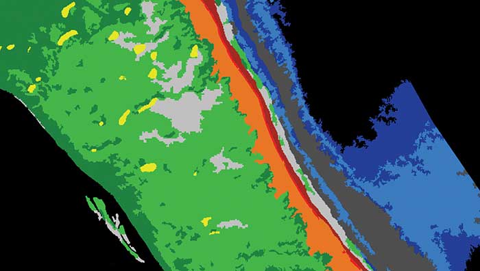
Image: TNC and Tama Group
To map reefs, Tama Group experts integrated the Dove satellite surface reflectance and Dove-derived bathymetry into eCognition. The software first delineates land and sea areas deeper than 15 meters. Based on depth data and known topographic characteristics, it then categorizes the overall reef structure, distinguishing reef crest, fore reef, back reef, patch and fringing reef. Once it defines the five reef classes, eCognition determines seagrass classes (dense and sparse), sand types and dredged areas, and then finishes with mapping the deeper hard-bottom-with-algae classes. In total, the software automatically classifies 13 different benthic habitats.
Using this workflow, eCognition successfully classified the shallow water benthic habitats of the entire Caribbean Basin in four months. The software exported each area as vector shapefiles, and Schill and his team downloaded them for analysis and quality control. Moving from reef to reef, they used field data to analyze the accuracy of the classifications, making manual corrections where needed.
To date, benthic habitat maps have been produced for 23 countries and territories across the insular Caribbean. In October, the final full set of benthic habitat maps for the insular Caribbean will be available online.
The largest seaportS on America’s West Coast are the Ports of Long Beach and Los Angeles, located next to each other in San Pedro, California. (Photo: Art Wager/E+/Getty Images)
The Port of Long Beach, California, is moving up and down because it sits on fault blocks that move like pistons due to subsidence caused by oil extraction. To accurately keep track of these movements, the port’s surveyors use GNSS receivers that receive corrections from continuously operating reference stations (CORS) operated by the port and by the City of Long Beach.
CORS corrections compensate for errors inherent in GPS — clock drift, orbit errors, signal errors and atmospheric errors.
Monitoring Subsidence. A monitoring receiver is placed on each fault block’s anticline, said Kim Holtz, director of survey for the Port of Long Beach. Her agency has 15 stations, along the coast, and a couple in the Port of Los Angeles. They were installed originally in the 1990s, using Trimble 5700s. “We are constantly monitoring to make sure that the fault blocks are not moving too much and that they are not moving horizontally other than all together, as the plates move to the north,” Holtz said.
Also, the Long Beach Energy Resources Department has 14 Trimble R9 base stations. While Energy Resources uses the equipment to get precise elevation differences and measure subsidence for movement of more than 0.025 feet, the port uses them mainly for horizontal measurements for construction.
The port’s hydrographic survey boat, the pilot boats, and the dig alert crew that marks utilities for construction operations also use the receivers to tie into the CORS network. “The stations are about eight or nine years old and Energy Resources is getting ready to replace all of them with Trimble Alloy GNSS reference receivers, over a three-year period,” Holtz said.
Digital Level Run. The port normally performs a digital level run from a tidal wave base station in San Pedro, which dates to the 1920s. “We run a level run from that and, at the same time, Energy Resources does a GPS subsidence survey, where they get elevation,” Holtz explained. “Last year, we combined the two surveys, to compare the data and see whether we could use some of their GPS data for our level run. It was very promising. We are going to do it again in November.
“Then, if it works, we will cut our level run, which normally takes two months, down to about a week or two. We will just come off of the main benchmarks on which Energy Resources puts a GPS elevation.”
To keep the elevations tight, more than 10 years ago Long Beach created its own geoid. “It is a hybrid of GEOID12B, and we’ve updated it a couple of times,” Holtz said.
Spot, the robotic dog from Boston Dynamics, is equipped with the Trimble SPS986 smart antenna to collect data. (Photo: Trimble)
Trimble and Boston Dynamics plan to integrate a variety of data-collection technologies with the Spot (robot dog) platform for construction and other site applications.
The jointly developed solution will combine the Spot robot’s autonomous mobility with Trimble’s data-collection sensors and field control software to enable automation of repetitive tasks such as site scans, surveying and progress monitoring, while taking advantage of the robot’s unique capabilities to navigate dynamic and potentially unsafe environments.
The relationship gives Trimble exclusive rights sell and support the Spot robot with integrated scanning, total station and GNSS technologies for the construction market.
The turnkey solution will streamline operation of the robot and provide quality control for missions, enabling construction project managers to easily get a clear picture of jobsite progress on an ongoing basis. Trimble technologies integrated with the robot will enable accurate, scalable and rapid data acquisition, while Trimble’s construction collaboration platforms provide a continuous flow of information between field and office.
Mortenson, a Minneapolis builder, developer and engineering services provider, is one of the first customers to leverage the new technology combination. To eliminate jobsite waste and increase efficiency, the Mortenson team has been piloting Spot robots with the Trimble SPS986 GNSS solutions to autonomously navigate challenging exterior construction environments such as solar farms, continuously documenting site conditions.
An automated and repeatable approach to field-data capture can provide Mortenson with real-time awareness of project status, helping to accelerate project delivery. Through Trimble’s Early Experience Program, contractors such as Mortenson have advanced access to this technology for the purposes of evaluating its suitability in actual construction projects.
The Trimble SPS986 smart antenna. (Trimble: photo)
“Robots will play a crucial role in automated construction workflows and can augment the human workforce by handling dirty, dull and dangerous tasks,” said Martin Holmgren, general manager, Building Field Solutions at Trimble. “Our experience with early adopters like Mortenson gave us visibility into the transformative potential of an integrated solution that seamlessly marries a world-class robot with construction-specific sensors and workflows. We’re excited about this alliance and the potential to bring unprecedented improvements in safety, quality and productivity to our construction customers.”
“We believe the combination of Trimble’s experience and industry leadership in construction technologies and Boston Dynamics’ Spot can transform the way the industry operates,” said Michael Perry, vice president of business development at Boston Dynamics. “The integrated solution will enable any jobsite leader to deploy Spot and Trimble technologies to get an accurate view of construction progress through real-time data collection. With a more comprehensive view of site activity, project managers can take proactive measures to ensure on-time, on-budget and safer project delivery.”
The integrated solution is expected to be available by the second quarter of 2021 through Boston Dynamics, Trimble and select BuildingPoint and SITECH distribution partners in the U.S., Canada, the United Kingdom, the European Union, Australia, New Zealand and Japan.
Through Trimble’s Early Experience Program, select customers will have the opportunity to preview development of the solution in advance of general availability.
The global smart agriculture market size was valued at $16,747.7 million in 2019 and is estimated to reach $29,234.6 million by 2027, with a CAGR of 9.7% from 2021 to 2027, according to Valuates Reports.
The market is expected to rise as a result of rising population, increasing strain on the food supply system, the growing use of new technology in agricultural products and farmers’ growing focus on tracking livestock.
According to the report, the global competition between players will be increased by new players joining the global smart agriculture market, which will in turn increase advancements in technology. Top companies in the smart agriculture market include Trimble, Deere & Co., Topcon Positioning Systems, DeLaval, AgEagle Aerial Systems, Afimilk, Raven Industries, Ag Junction, AGCO Corporation and GEA Group, the report said.
Current trends influencing smart agriculture market size include the growing adoption of automation and control systems, such as GPS/GNSS receivers, irrigation controllers, and guidance and steering systems, has created a new approach to farming practices. The report said it also expects growing investment, R&D spending on agricultural technology and increased popularity of land-based recirculating aquaculture systems to fuel market growth.
The report also touched on COVID-19’s impact on the smart agriculture market, noting the market is expected to see a marginal fall in 2020 as movement restrictions and lockdowns have led to supply chain disruptions.
Despite this, the precision farming segment held the largest market share in 2019 and is expected to retain its dominance during the forecast period, the report said. North America is expected to hold the largest smart agriculture market share during the forecast period, and Asia Pacific is expected to witness the highest growth during the forecast period.
In a special advertiser-sponsored section of our October issue, we spoke with prominent GNSS companies about their current solutions for today’s industry challenges.
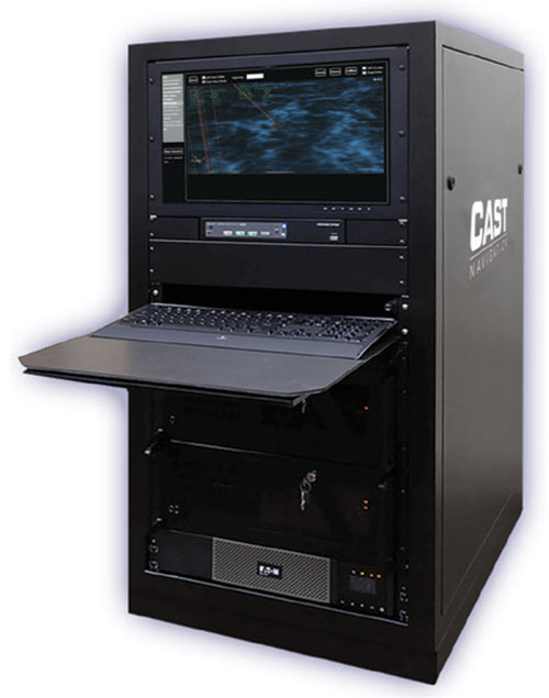
Q&A with CAST Navigation
Answered by Lou Pelosi, vice president
Lou Pelosi, vice president
Q: What is your most proven GNSS solution?
A: CAST Navigation does not supply GNSS receivers (GNSS solutions), rather we manufacturer GNSS simulators which are used to test GNSS receivers. CAST has had the most success with our GNSS/INS simulator. It provides an Embedded GPS Inertial (EGI) navigator with coincident GPS and inertial data. The EGI “thinks” it is moving while it remains stationary.
With our GNSS/INS simulator, the operational flight program of the EGI can be tested. During development of a platform’s navigation system, the CAST simulator is used to recreate the identical test conditions as the EGI’s software is modified. Once the platform’s navigation system is finalized, the output of the EGI is used to drive other systems, such as flight control or radar.
The GNSS/INS simulator can also include Controlled Radiation Pattern Antenna (CRPA) test features. If the EGI being used by the platform has an anti-jam antenna, the simulator can also test that feature.
The CAST GNSS/INS simulator has proven to be a key piece of equipment in system integration laboratories as new aircraft are developed.
Photo: CAST Navigation
Q: What are the solution’s key specs?
A: A key element of our GNSS/INS simulator is the inertial model contained in the simulator. It is a whole value inertial model rather than an error model. In its normal state, it reacts in the same manner as the actual inertial of the EGI. It also had degraded modes that are used to simulate hardware failures. When analyzed by the EGI manufacturers, its noise characteristics are almost identical to fielded navigation systems.
Q: What are the solution’s key features and benefits?
A: The most obvious benefit of using a CAST GNSS/INS simulator is cost savings. Even with the cost of lab equipment and personnel, there is still a savings over flight testing. A key feature of using a simulator for testing is its repeatability. Every time you rerun a test; the conditions are the same. In the real world, the satellites change constantly. Being able to accept real-time trajectory data is another key feature of CAST simulators. Instead of using our internal point mass model for scenario generation, an actual flight profile can be sent to the simulator from an external computer.
CAST has also been authorized by the GPS Directorate to provide classified functions to authorized users. Available options include Y-code, SAASM and M-code MNSA.
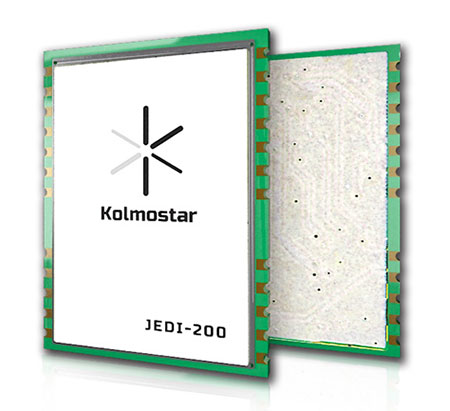
A: Kolmostar specializes in ultra-low-power, instant cold-boot GNSS positioning solutions for internet of things (IoT) applications, mobile devices and beyond.
Q: What are the solution’s key specs?
A: Our advanced GNSS positioning module JEDI-200 is specially designed for location-based IoT applications such as asset tracking, fleet management, pet/livestock tracking, smart wearables and share economy. It is also optimized for integration with LPWAN (low power wide area network) technologies such as LoRaWAN®/NB-IoT/LTE-M to provide the ultimate ultra-low-power profile for IoT applications. There are two outstanding advantages of JEDI-200: ultra-low-power and instant cold-boot. With 25 mW power consumption and the revolutionary 1-second TTFF (time to first fix), JEDI-200 is able to reduce the energy consumption to get one position fix by up to 120x compared to traditional GNSS modules on the market.
Q: What are the solution’s key features and benefits?
Photo: Kolmostar
A: GNSS/GPS sensors are one of the most power-consuming sensors in IoT or mobile devices. Battery life will be significantly shortened when GNSS/GPS sensors are turned on. Hence, many IoT and mobile devices either do not include GNSS/GPS sensors or have to equip themselves with very large batteries, incurring much inconvenience and cost. Kolmostar’s ultra-low-power and instant cold-boot JEDI-200 module is specially designed to solve this long-standing industry pain point.
With its ultra-low-power feature, JEDI-200 is able to reduce the energy consumption to get one position fix by up to 120x when compared to traditional GNSS modules. IoT devices with very limited-sized batteries are now able to have GNSS positioning ability while still maintaining a battery life up to 10+ years. Another key feature of JEDI-200 is instant cold boot. Unlike traditional GNSS modules’ 30-second TTFF in cold boot, JEDI-200 can achieve an instant 1-second TTFF, providing a better and more seamless customer experience when short latency/response time is particularly desired in certain applications. In addition, JEDI-200 is optimized for LPWAN technologies such as LoRaWAN®/NB-IoT/LTE-M, further reducing both the cost and the power consumption of devices’ wireless communication, which is another big challenge most IoT and mobile devices previously faced.
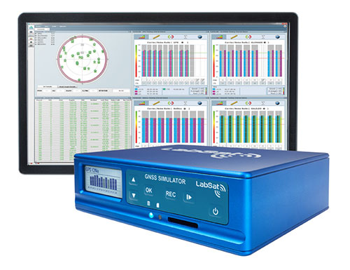
A: The LabSat 3 Wideband GNSS simulator offers multi-constellation and multi-frequency capabilities for reliable, repeatable and consistent testing. Its one-touch Record and Replay provides an efficient way to test and develop GNSS receivers without the cost, inconvenience and limitations of live-sky signals. Combining LabSat with the custom simulation software SatGen enables the creation of GNSS RF I&Q or IF data files based on a bespoke scenario, allowing for almost any kind of test at a set time, date and location.
Q: What are the solution’s key specs?
A: With three channels, a bandwidth of up to 56 MHz and 6-bit sampling (3-bit I and 3-bit Q), LabSat 3 Wideband can handle almost any combination of constellations and signals that exists today, with plenty of spare capacity for future planned signals.
Q: What are the solution’s key features and benefits?
A: LabSat 3 Wideband is small and affordable, making it an ideal solution for companies to provide their employees with a suitable method of testing their GNSS devices whilst working from home. In addition to its compact size, an internal battery delivers up to two hours of run time to record scenarios in even the most challenging field environments.
Photo: Labsat
It is incredibly user friendly with one touch record and replay and an HTML interface that makes setup simple and problem-free. A range of additional signals can also be recorded and synchronized to the GNSS input: dual-CAN, RS232 and digital inputs are simultaneously captured, increasing the level of playback realism and allowing for a wider range of testing.
The latest version of SatGen can be used to create a single scenario containing all the upper and lower L-band signals for GPS, Galileo, GLONASS, BeiDou and NavIC, and takes advantage of the LabSat 3 Wideband’s ability to read RF data at up to 95 MB/s. Creating an artificial scenario using SatGen allows for precise control of the data content, creating a standardized file for repeatable testing and carrying out true comparisons between receivers.
The versatility of the LabSat 3 Wideband makes it a familiar sight on the desks and benches of technology companies around the world. From GNSS device and application testing to receiver sensitivity and end-of-production-line testing, LabSat 3 Wideband is a perfect testing partner.
Q: What is Trimble OEM GNSS’ most proven GNSS solution?
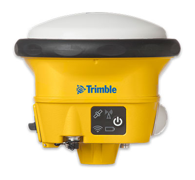
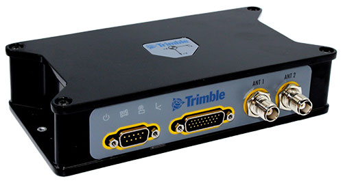
A: The Trimble BX992 is the flagship product from the Trimble OEM GNSS portfolio, proven in multiple environments and applications. Powered by the BD992-INS receiver module, this rugged yet compact enclosure allows original equipment manufacturers and system integrators to rapidly integrate precise position and orientation data to guidance, control and autonomous applications. Continuous data sets collected from test sites and real-world applications around the world have been used to create a powerful engine that performs in the most challenging of GNSS environments.
The Trimble BX992. (Photo: Trimble)
Q: What are the solution’s key specs?
A: The Trimble BX992 delivers low-latency 100-Hz centimeter-level positions with tight integration of IMU sensor data and GNSS observations in the RTK/RTX engine. The rugged IP67 enclosure supports multi-frequency tracking from GPS, Galileo, GLONASS, BeiDou, QZSS and NavIC constellations. The dual-antenna inputs allow rapid and robust alignment of onboard gyro sensors. With Trimble RTX correction services, the BX992 delivers reliable, high-accuracy positioning without a local base station or cell modem.
Q: What are the solution’s key features and benefits?
A: The BX992 is a full-featured solution with an onboard spectrum analyzer, a critical tool for developers to identify interference from unwanted signals, thus allowing products to be released to the market within specification and on schedule.
John Fischer, vice president, advanced R&D, Orolia
In 1990, I had just left the military electronics industry (radars, electronic warfare) and entered the growing wireless telecom industry. Recall, this was at the end of the Cold War with shrinking U.S. defense budgets. Alas, after eagerly waiting for the full operational performance of GPS throughout the 1980s, I unfortunately missed its early successes.
I spent the 1990s in startups, working to provide wireless alternatives to dial-up and leased lines. We founded Clearwire, which eventually became WiMax — the broadband wireless on-ramp to this new “information superhighway” we now call the internet.
However, within a few years, we started to look for a way to synchronize our adjacent basestations to avoid interference at overlapping regions. Those of us who came from the military navigation sector turned to GPS. We began to use a GPS receiver to give us a 1PPS sync.
This worked well, although we had to train our installers not to put the GPS antenna high up on the tower with all the others, but low, away from the transmission beams. It was hard for them to believe we got better reception on the ground than up high!
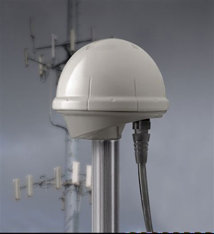
The Trimble Accutime 2000. (Photo: Trimble)
By the late 1990s, Trimble had introduced its Accutime 2000, which made our lives easier. (Everything futurist in those days was called Something-2000 — the new millennium was approaching). Today, it is the standard for time sync, but back then, it was novel.
When I think of the progress in terms of Moore’s Law (semiconductor performance doubles every 18 months), we have been through 20 doublings since 1990. That is an improvement factor of a million!
However, technological advancement alone does not account for GPS’ huge success. The fact that the U.S. military opened its system for use by everyone in the world, and the continued cooperation of all nations in making all GNSS systems interoperable, is mind blowing.
We are living in the world that John Lennon only “Imagine(d)”: all the people sharing. In 2020, we are now focused on GNSS vulnerabilities and protecting the integrity of GNSS signals, which are such an integral part of our daily lives. GPS is truly a modern miracle.
Stuart Riley, vice president of GNSS technology, Trimble
Over the past 30 years, GPS World has been at the forefront of the transition of GPS from obscure technology to ubiquitous utility. The magazine was first published before the satellite constellation achieved Initial Operational Capability (IOC). In fact, it preceded Operation Desert Storm, which created unprecedented publicity and demand for GPS equipment; and has documented a period of unprecedented increase in the rate of change in the technical disciplines.
Thirty years after the Wright brothers’ initial flight, commercial air travel remained expensive, uncomfortable, and available to relatively few people. Compare that to GPS and GNSS — in 30 years the technology has moved from 50-pound receivers powered by car batteries to residing in the pockets and on the wrists of billions of people.
In 1978, the year the first GPS Block-I satellite was launched, Trimble was founded. Trimble’s first product was a Loran receiver in 1980, followed by the world’s first commercial GPS product in 1984. The year the magazine was launched, Trimble became the first publicly traded GPS company in 1990. Positioning technology is in Trimble’s DNA and the foundation for helping transform industries such as construction, agriculture, transportation, geospatial and more.
Two factors drove GPS from obsurity to ubiquity: Rapid technological advances (electronics, software, communications, and increasing numbers of satellites) combined with innovations using positioning to benefit large numbers of users across disparate applications. Think of it as “Moore’s Law meets market demand.”
A Malaysian tribe and the Trimble 4000SLD, the first kinematic “backpack” GPS receiver. Weighing 44 lbs. without batteries, the receiver was introduced in 1988. (Photo: Trimble)
The key to GNSS’s growth is its adaptability. By serving a broad range of industries, GNSS manufacturers addressed widely differing needs for precision, form factors, interfacing, and availability of positions. The markets drove the development of more-capable and cost-efficient solutions and injected varying requirements for performance and functionality.
Recent advances illustrate the ability of GNSS technology to react to market needs. Satellite-delivered PPP corrections enable users to achieve real-time centimeter accuracy with fast convergence time almost anywhere on Earth. Low-cost, high-performance inertial sensors boost performance in challenging environments. Software-defined high-precision GNSS receivers, coupled with augmented reality on consumer devices (phones and tablets), open the door to innovation in as-yet-undiscovered directions.
GNSS is playing a key role in a broad range of applications. For example, compact, high-precision receivers are transforming work by delivering higher levels of productivity, reliability, safety and flexibility in industries including automobile and trucking, precision farming, and earthworks and construction. Future applications are expected to increasingly integrate GNSS with other sensors to drive productivity and safety for autonomous applications.
It took less than 30 years to move from static post-processed positioning to holding centimeter precision in your hand. For those of us who experienced the early days, GNSS has changed the world in ways we never imagined. The next three decades will see GNSS embedded into applications unimaginable today.
And to GPS World: Congratulations and thank you for 30 great years of pioneering the education, awareness, and promotion of the GNSS industry.
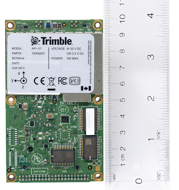
Applanix, a Trimble company, has introduced the Trimble AP+ Air OEM solution for direct georeferencing of airborne sensor data.
The solution enables users to accurately and efficiently produce maps and 3D models without the use of ground control points.
The Trimble AP+ Air is a powerful solution for manned platforms, yet small enough for use on unmanned aerial vehicles (UAVs). It is also compatible with virtually any type of airborne remote sensor, including photogrammetric cameras, lidar, hyper and multispectral cameras, and synthetic aperture radar.
Comprised of next-generation compact, low-power hardware, the Trimble AP+ Air features dual embedded survey-grade GNSS chipsets, an onboard inertial measurement unit (IMU), an external IMU, and the all-new Applanix IN-Fusion+ GNSS-aided inertial firmware. It is configurable to support the direct georeferencing accuracy demands of low-flying UAVs to high-altitude manned platforms.
“We have taken the most advanced features of Applanix direct georeferencing and Trimble GNSS technology and packaged them into a powerful new, compact and versatile solution,” said Joe Hutton, Applanix’ director of inertial technology and airborne products. “It provides the flexibility required by systems integrators to embed a single hardware solution that can then be configured to meet the different direct georeferencing needs of a specific sensor type, whether flown on a UAV or manned aircraft. It truly is an ‘integrate once, use many times’ solution.”
The Trimble AP+ Air is fully supported by the Applanix POSPac MMS post-processing software, which features CenterPoint RTX post-processing for centimeter-level positioning anywhere in the world without the need for base stations. These capabilities make the solution ideal for integrators to produce a highly efficient airborne mapping system.
For lidar integrators, the Trimble AP+ Air is compatible with the POSPac MMS LiDAR QC Tools for computing boresight as well as adjusting the relative accuracy of the POSPac trajectory being used to generate the point cloud. For integration with cameras, the solution is supported by the POSPac MMS Photogrammetry Tools for computing boresight and performing camera IO quality control.
The Trimble AP+ Air OEM solution and POSPac MMS are available through Applanix sales channels.
Thirty years ago, more than a decade before most people had even heard of GPS, receiver manufacturers and surveyors were already improving on it by providing and using correction services to compensate for errors in the system—including clock drift, orbit errors, signal errors, atmospheric errors and multipath.
Today, dozens of public and commercial correction services enable users to achieve accuracies of decimeters, centimeters or even millimeters. Also, many GNSS processing services correct measurements taken in the field using data from reference points. Increasing positioning accuracy has become the cornerstone of modern GNSS practice.
The current boom for correction services is driven mostly by the demand for high accuracy from the automotive industry (including the development of self-driving cars), as well as smart consumer devices and various forms of automation. Automotive companies and telecoms are deploying infrastructure around the globe to provide centimeter-level positioning. GNSS satellites also can transmit corrections directly, as the Japanese CLAS service from the QZSS constellation does, and Galileo’s High-Accuracy Service (HAS) soon will. To compensate for receiver-side issues — multipath, jamming and spoofing — some GNSS receivers also incorporate advanced positioning algorithms.
Clock and orbit errors are specific to each satellite; they do not depend on the position of the receiver. But atmospheric errors are introduced when the signal travels from the satellites to the user. Reference stations (base stations) of GNSS receivers installed at fixed and precisely surveyed positions provide corrections that compensate for both sets of errors to the rovers carried by field crews. When connected, reference receivers spread over a geographic area form reference networks, such as that of continuously operating reference stations (CORS). Achieving maximum accuracy requires initializing the receiver, which can take a few seconds to several minutes, depending on the type of corrections.
Established and new methods
Two established methods have been used for decades.
Real-time kinematic (RTK). In RTK, a receiver obtains correction data from a single base station or a local reference network in the same area.
Precise point positioning (PPP). While accessible from anywhere in the world, receiver initialization for PPP can take up to 30 minutes. Also, a few PPP correction services only provide corrections for satellite clock and orbit errors and not for atmospheric errors, limiting users to a lower accuracy level than with RTK.
Hybrid PPP-RTK. In recent years, new methods have emerged. Hybrid PPP-RTK combines near-RTK accuracy and quick initialization times with the global access of PPP. It relies on a network of reference stations within about 150 kilometers of each other. The stations collect GNSS data and calculate both satellite and atmospheric correction models. The network then broadcasts these corrections via internet, satellites or cellphone towers to subscribers, who can use them to achieve sub-decimeter accuracy.
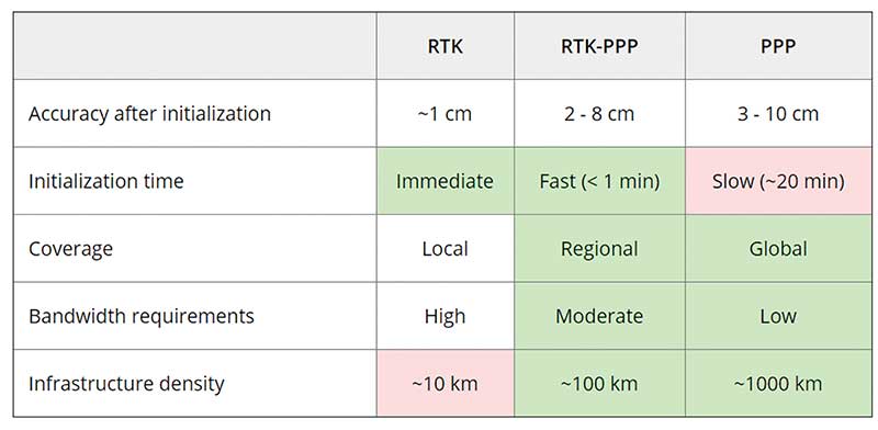
Each of these methods has advantages and disadvantages (see table 1). RTK, which relies on communication between the user and the local correction service, provides centimeter accuracy over small areas. PPP-RTK and PPP broadcast corrections and require a lighter infrastructure, making them scalable for mass-market and industrial applications. The new services are cheaper and more user-friendly than traditional correction services.
TABLE 1: Differences of various correction methods. (Chart: Septentrio)
CORS/VRS
Traditional reference networks — often called CORS or virtual reference station (VRS) networks — have long been a source of differential GPS (DGPS) and RTK corrections, mainly for surveying and mapping applications, which require high accuracies.
“Most CORS in the United States are strictly for providing high-accuracy correction data to GNSS users who need to know their position to less than an inch,” said Alex Ngu, applications engineer at Trimble. “However, some — like Utah’s TurnGPS network and the North Carolina Geodetic Survey (NCGS) — have considered dabbling in using them to double up for weather monitoring.” In some regions, such as Japan and Washington state, CORS are also used to study plate tectonics and provide early warning of earthquakes.
CORS receivers often operate in remote locations and may be powered by solar panels. Therefore, they require low power consumption and the ability to configure, run and update remotely. They also need to archive on-board measurements and withstand harsh environments.
Changes in the market
As the market for GNSS corrections changes, so does the role of CORS networks. They are increasingly used for industrial automation that needs centimeter accuracy, including construction and agriculture. “Now, due to the growth in autonomous systems, such as autonomous cars, people are looking at corrections in a completely different way and with more focus on mass markets,” said Gustavo Lopez, market access manager at Septentrio. Septentrio lets customers choose which correction service to use.
“CORS/VRS networks will keep focus on performance and on adding constellations and signals, but nothing major is expected to happen in these traditional systems,” Lopez said. They will continue to exist because they focus on centimeter-level accuracy for survey, construction, mining, machine control and precision agriculture. “What will really change the market are these new services with 10-cm to 20-cm accuracies, which also offer a new way of delivering the data, namely broadcasting rather than using two-way communication methods.” This helps with adoption by emerging applications, Lopez said.
He predicts that applications needing 10- to 50-centimeter acurcy will migrate to cheaper services, including new consumer applications, advanced driver-assistance systems (ADAS), professional applications such as robotics, UAVs, logistics and internet of things (IoT) applications.
Mobile technologies adopting dual-frequency chipsets also will need correction services. “We will see more and more telecoms interested in providing GNSS corrections as a service, as is already the case in Asia and Europe,” Lopez said. “A few CORS/VRS networks will try to capture part of this emerging applications market by reusing their technology or partnering with other companies to provide a more transparent solution.”
One might think that the rapid expansion of the market for corrections would make it possible for traditional CORS networks to make 1-cm accuracy available at a much lower price. The roadblock is high infrastructure costs, Lopez explained. CORS/VRS networks are expensive to maintain because they require a high density of stations. New services that use broadcasting technology and PPP-RTK positioning modes rely on less dense networks.
New uses for old CORS
A key benefit of a VRS is that performing RTK positioning across the area it covers does not require guarding a separate GPS base station. Using VRS, the CORS network acts essentially as a continuous reference station within the entire network, enabling RTK positioning using a single rover in the field.
Randy Osborne, VRS network manager at Louisiana State University’s Center for GeoInformatics, reports a growth in new applications beyond surveyors. VRS expanded to precision agriculture, and then into applications such as lidar and UAVs. “We are also seeing strange applications that we never thought of. For example, plumbing companies use it to navigate underground from a truck that has a position on the network, and then they vector from the truck underground into pipelines,” Osborne said. Subscribers also include companies performing survey work for fracking and petrochemical projects.
OSR vs. SSR
Most GNSS correction services are based either on the observation state representation (OSR) or on a state space representation (SSR) of the errors. OSR and SSR use different techniques, delivery mechanisms and core technologies.
OSR. Legacy GNSS correction service providers supply OSR correction services; examples are RTK and networked RTK (RTN). They rely on transferring corrected GNSS observations from the nearest reference station to the rover using a standardized format. They focus on a geographic region and target surveying, machine control and precision agriculture, providing centimeter-level accuracy up to about 30 kilometers of the nearest reference station. Because these services require bi-directional communications and large bandwidth, it is hard to ramp them up for mass-market applications.
SSR. By contrast, new players in the market for correction services, as well as some of the larger legacy ones, provide SSR correction services. SSR uses a network of reference stations to model major errors over large areas. They then transfer this model to the rovers, which create local error models and apply them to their GNSS observations. Depending on the service, accuracy ranges from less than 5 cm to 20 cm, convergence times from 10 seconds to 30 minutes, and coverage from continental to global. Because SSR corrections are broadcast, they can be more easily distributed through internet connections and L-band satellite channels. Because all the rovers rely on the same stream of GNSS correction data, SSR services work well for mass-market applications. The growth in SSR technology is driven mainly by the needs of the automotive industry but is sufficiently generic for adoption in other markets.
The challenge of vertical accuracy
A CORS receiver stands atop the Old River Auxiliary Control Structure, a floodgate system in a branch of the Mississippi in central Louisiana. (Photo: Trimble)
While OSR and SSR have comparable accuracies on a horizontal plane, they differ greatly in their vertical accuracy and initialization times, Osborne said. “When we look at CORS for active control and positioning in the National Spatial Reference System, we are mainly trying to get a handle on the vertical part, as it is the hard problem to solve,” he said.
High-precision vertical accuracy is a challenge for any GNSS-based method. Conventional surveying is still the gold standard. With differential leveling, like with digital levels, results in millimeters are possible. Post-processed GNSS, using data from a good geometry of CORS or base data, can yield results under 2 cm vertical, as can real-time OSR methods like RTK and RTN. SSR solutions, like PPP and hybrids, are presently achieving 5 cm at best. An Achilles heel for SSR vertical solutions is the lack of data for localized sources of error, like tropospheric conditions. Semi-dense networks of CORS can feed ionospheric data to speed PPP convergence, but not the level of tropospheric data needed to match the vertical results that OSR and conventional methods can.
Trimble
Trimble GNSS base-station receivers have been used for 40 years on every continent, according to the company. Today, products in use as CORS stations typically are Alloys, NetR9s and NetR5s. The company operates more than 300 networks worldwide, incorporating more than 5,000 CORS receivers.
Trimble offers a full spectrum of solutions, services and subscriptions related to CORS networks. They range from supplying CORS software, hardware and services, to providing network management services to run a secondary backup system for a network, or even operating a network on behalf of its owner. For those who just want a high-accuracy correction to support their surveying, GIS or machine guidance and control work, “Trimble operates one of the largest CORS networks in the world to which users can subscribe — Trimble VRS Now, Trimble RTX and OmniSTAR services,” Ngu said.
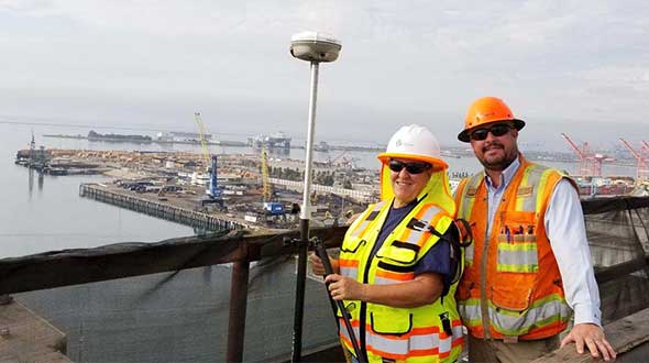
Feature photo:
In Long Beach, California, correction services support the 250-foot-high Gerald Desmond Bridge project. Trevor Rice (left), president of D. Woolley & Associates, joins Kimberley Holtz, director of survey, Port of Long Beach. (Photo: Trimble)
The Government of Nepal has completed fieldwork for measuring Everest’s height using GNSS equipment from Trimble, including the robust R10 receiver.
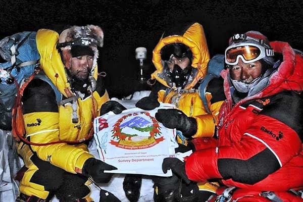
The Survey Department of the Government of Nepal has completed fieldwork for the National Initiative for the Measurement of the Height of Sagarmatha (Mount Everest). The Nepali survey team summited at 3 (local time) May 22, 2019 (by the Nepali calendar, that’s २०७६ जेठ ८, or June 8, 2076).
The summit team of Chief Survey Officer Khim Lal Gautam and Survey Officer Rabin Karki was supported by mountain guide Tshiring Jangbu and two of his fellow Sherpas.
The ascent was dark, windy and treacherous — the team had to make optimal use of the limited time that the hazardous conditions and their oxygen supplies afforded. The primary surveying task was to collect GNSS observations with the Trimble R10 GNSS receiver they carried.
On the summit: Chief Officer Khim Lal Gautam, Survey Officer Rabin Karki, Sherpa Tshiring Jangbu, and the Trimble R10. (Photo: Trimble)
Due to the limited time window on the summit, they had essentially one shot at the GNSS observations. The R10 was configured to begin collecting observations on power-up. During training and test observations before the ascent, the R10 had proven to be exceptionally reliable, with no malfunctions.
Compact size, light weight and durability were important factors for the receiver chosen for the summit observations. The IP67-rated R10 with internal battery weighs 1.12 kg (2.5 lb.) and operates in a temperature range of –40° C to +65° C (–40°F to +149° F). Its solid alloy housing withstands a 1-meter drop. The only concern for the team on the final ascent was to keep the battery and spares warm.
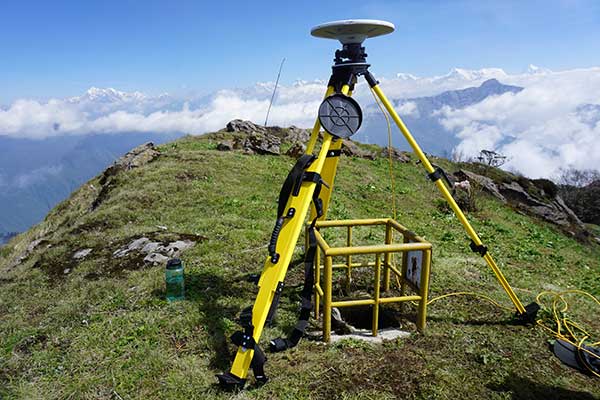
The R10 recorded 1 hour and 16 minutes of GNSS observations. The static data (observations from GPS, GLONASS, Galileo and BeiDou) was post-processed using Trimble Business Center software together with observations from eight GNSS reference stations established as an active control network for the survey. Several of the reference stations were Trimble NetR9 network receivers with Zephyr Geodetic antennas.
The team also used a compact ground penetrating radar (GPR) instrument to determine the distance between the top of the ice/snow cap on the summit and the highest point of solid rock beneath.
Many of the successive accepted heights for Everest have been to the top of the ice cap, which can vary seasonally by several meters. A goal of the survey is to provide heights for both aspects of the peak. An additional reason to establish a new height for Everest is to determine whether, and by how much, the 2015 earthquakes in the region altered the mountain.
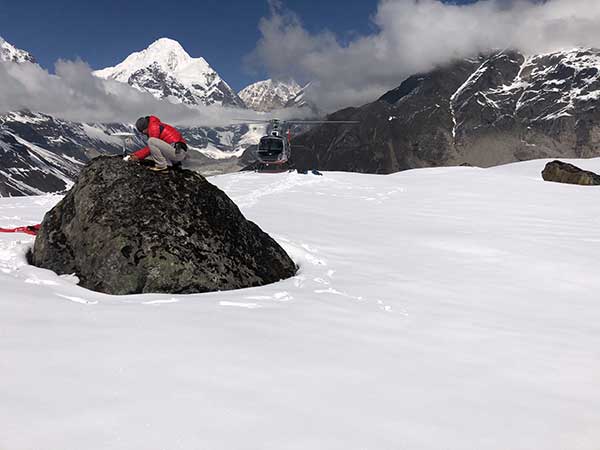
Photo: Trimble
While the Nepalese survey team’s GNSS observations on the summit will yield the height, the final orthometric elevation will be achieved by applying an updated gravity model. The gravity model was refined from supporting surveys on the mountain and surrounding region.
A total of 298 new gravity observations were performed over several years, with companion GNSS observations on each control point. More than 248 kilometers of precise leveling, supplemented with trigonometric leveling, was performed for the network of control and base receiver locations. Instruments employed for these terrestrial surveys included Trimble DiNi levels and S9 total stations.
Trimble GPS/GNSS instruments have been to the Sagarmatha summit on multiple occasions, including in 1990, 1998, 2005 and 2012. The R10 represents the lightest and most compact of these to date.
By prior agreement between Nepal and China, the results of the 2019 Nepali survey, and a May 2020 Chinese survey, will be jointly announced. Official results are expected this summer.
Featured photo: A GNSS reference station network was established before the survey to provide data for post processing, and to support additional surveying and geophysical studies of the region. (Photo: Trimble)
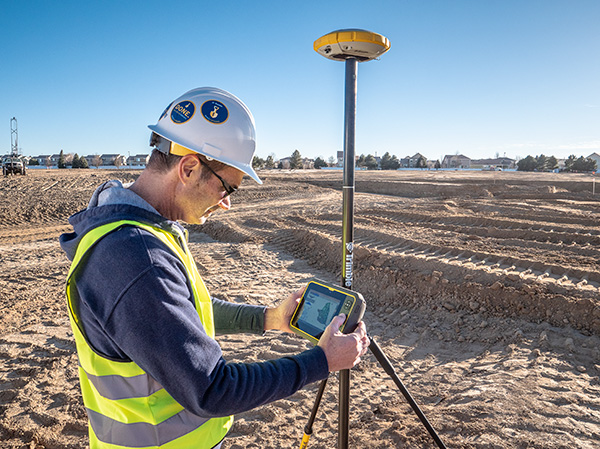
Trimble GNSS integrates with PointMan field applications to identify, capture and record the precise geospatial location of utilities
ProStar has joined Trimble’s GIS Business Partner Program. As part of the program, ProStar has implemented the Trimble Precision SDK (software developer kit) to integrate high-accuracy positioning capability in its PointMan mobile application running on smartphones and tablets using Trimble GNSS receivers.
ProStar provides field crews with an easy-to-use mobile data collection solution designed to capture, record and provide real-time visualization of the precise locations of subsurface infrastructure, while utilizing a centralized database to permanently and securely store and share utility location records in the cloud.
By adding the Trimble R Series and Trimble Catalyst receivers to the ProStar workflow, users can confidently access high-quality data and identify potential conflicts to avoid accidents, disruption of services and costly delays to infrastructure projects impacted by not knowing the precise locations of buried utilities.
“Together, Trimble and ProStar are changing the way construction companies, engineering and surveying firms as well as government transportation agencies capture, store and utilize utility infrastructure data. By leveraging the power of geospatial technology, they are able to make more informed decisions in the field,” said Stephanie Michaud, strategic marketing manager, Trimble Survey & Mapping field solutions. “Through this collaboration with ProStar, we are committed to integrating Trimble technology into ProStar’s cloud and mobile solutions to enhance safety protocols on site, reduce project costs and make a safer work environment.”
“We’re excited about this new collaboration and the integration of our PointMan software with Trimble’s high-accuracy GNSS receivers,” said Page Tucker, president & CEO of ProStar. “Creating a seamless integration with Trimble high-accuracy receivers and our PointMan software is a game-changer that will now provide one of the most comprehensive and precise field data collection solutions in the industry.”
About ProStar
ProStar specializes in the development of Precision Mapping Solutions. ProStar’s Solution is natively cloud and mobile and offered as Software as a Service.
ProStar’s Solution is designed to improve the business operations of any industry that requires the precise location of sub-surface infrastructure including utility, oil & gas, construction, engineering & surveying, 811 and contract locating.
ProStar’s Solution enables real-time access to precise location information including in the office and out in the field. Knowing the type, precise location and condition of what lies below the earth’s surface can significantly decrease liabilities and increase productivity during construction and maintenance activities.