By Oliver Montenbruck, Andre Hauschild (DLR/GSOC), Stefan Erker, Michael Meurer (DLR/IKN), Richard B. Langley (UNB), and Peter Steigenberger (TUM)
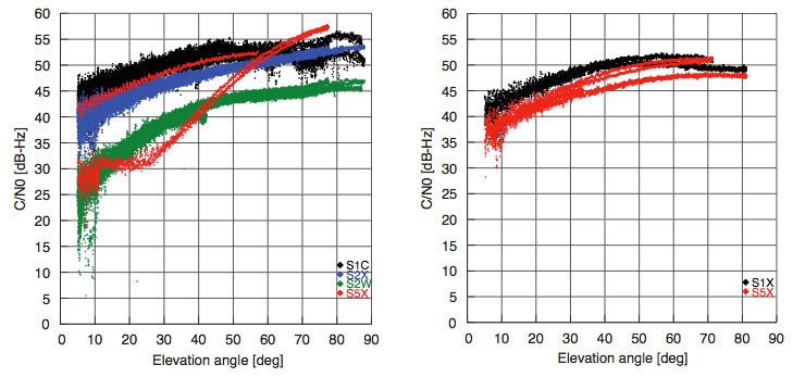
The L5 signal of the new Block IIF satellite shows a very favorable signal strength (Fig. 1), which is somewhere in between the L1 and L2C signal strength for the employed antenna and slightly higher than that of the GIOVE-A/B satellites. While the L5 test signal of the second-last Block IIR-M satellite (PRN1/SVN49) is transmitted through a narrow beam antenna and shows a steep variation with elevation angle, the new satellite exhibits an almost constant flux irrespective of the boresight angle.
Following the successful launch of the first Block-IIF GPS satellite (PRN25/SVN62) on May 28, 2010 (UTC), and the activation of the legacy signals on June 6, users around the world have eagerly awaited the first transmission of PRN25 signals in the L5 band.
In June, at last, the L5 payload was activated for more than five hours transmitting nominal signals with the PRN25 ranging code. This enabled standard tracking receivers to collect the first real L5 measurements from the new satellite.
Scientists of the German Aerospace Center (DLR), the University of New Brunswick (UNB), and the Technische Universität München (TUM) spotted the first L5 data at 15:17:11 UTC from a station in Fredericton, Canada, followed a second later by stations in Japan, Singapore, the Canary Islands, and Germany. The stations are part of the CONGO network, which is the first global network of tri-band (L1/E1, L2, L5/E5a) GNSS receivers monitoring the GPS, GLONASS, GIOVE, and SBAS satellites. For background on the CONGO network, see the September 2009 GPS World article.
Fig.1 Carrier-to-noise-density ratio of GPS (left) and GIOVE-A/B signals measured at the Wettzell station on June 17, 2010. Red curves refer to signals in the L5/E5a band and include data from the PRN1 test satellite and the new PRN25 satellite.
The L5 signal of the new Block IIF satellite shows a very favourable signal strength (Fig. 1), which is somewhere in between the L1 and L2C signal strength for the employed antenna and slightly higher than that of the GIOVE-A/B satellites. While the L5 test signal of the second-last Block IIR-M satellite (PRN1/SVN49) is transmitted through a narrow beam antenna and shows a steep variation with elevation angle, the new satellite exhibits an almost constant flux irrespective of the boresight angle.
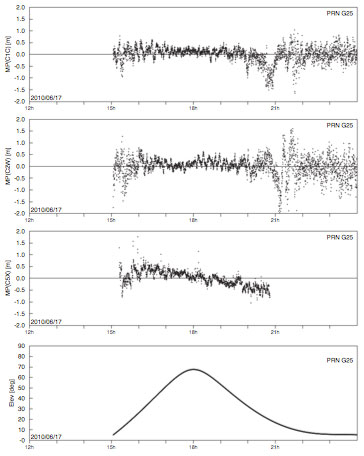
Fig. 2 Multipath plots of L1 C/A code, semi-codeless L2 P(Y) code, and L5 code tracking for the Singapore station of the CONGO network (10-second smoothing).
While the new Block IIF satellite has not yet been set healthy and made available for public use, the early measurements collected on June 17 already demonstrate good tracking quality. This is illustrated in Fig. 2, showing the so-called multipath combination for pseudorange measurements from L1 and L2 legacy signals (the upper two panels) as well as the new L5 signal for Singapore, which had continuous visibility of PRN25 during the period of interest. Except for low elevation angles that are affected by strong multipath from structures in the vicinity of the antenna, root-mean-square tracking errors well below 30 centimeters were obtained for all signals.
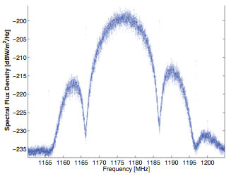
Fig. 3 L5 spectrum of PRN25 collected on June 17, 2010 with a 30-meter high-gain antenna at Weilheim, Germany.
In addition, the GNSS signal monitoring facility at DLR’s ground station in Weilheim has been used to record high-rate radio-frequency samples and spectra of the new signal, a snapshot of which is shown in Fig. 3. The raw sampling also confirmed that the L5 signal of PRN25 comprises both in-phase and quadrature modulation (in contrast to the PRN1 test signal, which contains a Q-component, only).
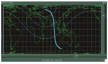
To the regret of U.S. scientists, the first publically traced L5 signals were only transmitted when the satellite was over Europe and Asia (see Fig. 4). Nevertheless, the test transmission provided an excellent sneak preview of what we can expect when the regular transmission starts. The satellite is presently expected to be set healthy and to start regular service by the end of August at the latest.
Fig. 4. The ground track of PRN25 during the transmission of L5 signals on June 17, 2010. Also indicated is the footprint of the satellite showing the 0°, 30°, and 60° elevation angle contours at the beginning of the transmission. The ground track is almost centered over Diego Garcia, one of the GPS monitoring stations.
Equipment. The CONGO network stations use JAVAD GNSS Triumph Delta-G2T/G3TH receivers. A Leica AR25R3 chokering antenna is used at Wettzell, while the Singapore station is equipped with a Leica AX1203+ GNSS antenna. The L5 spectrum was recorded with an Agilent PSA E4443A vector signal analyzer.
Beidou G3
China launched another Beidou/ Compass satellite, named G3, on June 2. By June 9, its apogee kick motor had placed the satellite in geostationary orbit at 84°38’ east, according to NORAD tracking reports.This is close to the position initially occupied by G2 (83°30’) before it started drifting. By June 9, G2 had drifted to 64°29’. By June 11, G3 had started transmitting signals on three frequencies.
China now has two properly functioning geostationary satellites in its second-generation system, out of a total of five it expects to place by 2012 for a regional operating system; also needed for this concept are four mid-Earth orbit satellites (one currently aloft), and five inclined geosynchronous orbit satellites (zero in orbit now). A planned global system would require 5, 27, and 3 satellites in GEO, MEO, and IGO orbits, respectively, by 2020.
Current regional-system signals on three frequencies use quadrature phase shift keying. Global-system signals will be binary offset carrier waveforms.
Opinions on SVN-49
The public comment period on proposed mitigation options for GPS satellite IIR-20M (SVN-49) ended May 28, and comments are viewable at www.regulations.gov under RITA Docket 2010–0002. Among others, the U.S. GPS Industry Council, NovAtel, Garmin, Septentrio, Raytheon, Boeing Commercial Airplanes division, General Motors OnStar, the European Commission, the MITRE Corporation, STMicroelectronics, the German Space Operations Center, and Cessna Aircraft have all filed comments expressing a preference for one option or another.
Unfortunately for the U.S. Air Force and the GPS Wing, no clear consensus emerges. Indeed, differences of opinion naturally follow the respective orientation of each company or organization toward their customers’ or members’ specialized needs.
Devote It to Science. Perhaps in recognition of this imbroglio, at the Air Force Space Command- Industry Exchange on June 15, Lt. Colonel Todd Parks briefed the PNT Functional Capability Team, explaining that the Air Force now was soliciting from industry “innovative applications” for the SVN-49 signal in space.This echoes a suggestion by Javad Ashjaee at last year’s unprecedented ION/ USAF session on SVN-49, where he proposed that the signal be used for studying multipath.
A website article at env-gpsworld-integration.kinsta.cloud/49opinions recaps commentary and preferred options from several companies and organizations.
The potential mitigations are each designed to reduce the impact of the unique nature — that is, errors — of the SVN-49 signal to a portion of the user segment. They are (so far):
1. Set healthy with current 152- meter antenna phase center (APC) and associated clock offsets.
2. Set healthy with factory APC offset.
3. Users switch to multipath-resistant receivers.
4. Modify receiver software to use look-up table corrections.
5. Increase user range accuracy (URA) index to a minimum value of 3.
6. Remove data modulation from L2 P(Y)-code, and
7. Change L2C PRN code to a “unique sequence.” (6 and 7 are considered a pair, to be jointly implemented for desired effect.)
8. Change SVN-49 from PRN-01 to PRN-32.
9. Use spare health code so future users could use SVN-49 despite unhealthy setting. For background on the SVN-49 situation, see Richard Langley’s Expert Advice column from August 2009. Briefly, the pseudorange data broadcast by the satellite contains larger than normal errors that vary according to the elevation of the satellite above the horizon.
The comments filed by the U.S. GPS Industry Council (USGIC), available as a PDF file at both URLs listed in this story, are the most detailed and extensive across all the options. However, the stated preference of the USGIC for Option 9 does not necessarily reflect agreement across all sectors of industry. As the USGIC points out, “Options 1 through 8 propose to designate SVN 49 as healthy using techniques that enable mitigation for some user applications, but that are unable to also mitigate adverse impacts to otherusers.”
As NextGen air traffic management increasingly relies on GNSS for safety-critical functions, some form of backup is needed in the event of GNSS signal loss, whether due to intentional jamming or other causes.
A group working under the auspices of the Federal Aviation Administration (FAA) Navigation Services Directorate recently prepared a study assessing non-GNSS navigation system architectures to provide alternate positioning, navigation, and timing (APNT) services for aviation users, to mitigate GNSS vulnerability to radio frequency interference (RFI). The APNT architecture would be based on selected elements of today’s terrestrial navigation network, possibly upgraded, plus new elements anticipated for the 2025 timeframe.
This article summarizes the scope and initial results of the study; to download the full paper, visit env-gpsworld-integration.kinsta.cloud/alternativePNT. As a result of the 2001 Volpe Vulnerability Study and subsequent U.S. government policy on PNT services provided by GPS, the FAA has begun investigating APNT concepts by which the safety, security, and efficiency of the U.S. National Airspace System (NAS) can be maintained in the event of a loss of GPS-provided PNT services. The sought-after APNT network should be cost-effective based on likely aircraft equipage in the 2025 timeframe.
The FAA recognizes that during migration from the current NAS to the Next Generation Air Transportation System (NextGen), reliance on PNT services will increase to support area navigation (RNAV), digital communications, and enhanced surveillance services. This paper, presented by the FAA to the International Civil Aviation Organization’s (ICAO’s) Navigation Services Panel in May, identifies three major areas of research and analysis. The APNT work represents a constructive response to concerns raised by the simultaneous 9/11 terrorist attacks and the Volpe Report on GPS vulnerability.
The first area of research proposes to investigate current distance measuring equipment (DME) to see if better RNAV services can be provided to current and future users, and to mitigate the possible problem of over-interrogation as demand on the system grows. The second area will investigate multi-lateration to see how the services based on systems currently being planned and fielded could be expanded or enhanced by synergy with other ground-based navigation systems such as DMEs.
The third area of interest will investigate the use of the current and future DME network, and potentially other ground-based equipment, to provide a robust RNAV pseudolite system broadcasting in the current DME L band. This third alternative receives the bulk of the attention of this two-page digest of the full paper.
Background
The United States is pursuing the NextGen air traffic modernization program to support a predicted increase in operations by a factor of 2–3 by 2025. Many of the new capabilities depend on PNT services provided by GNSS. Specifically, performance-based navigation (PBN) and automatic dependent surveillance broadcast (ADS-B) will be based on GPS with satellite-based augmentation systems (SBAS) and ground-based augmentation systems (GBAS). PBN and ADS-B will, in turn, support trajectory-based operations, area navigation (RNAV), required navigation performance (RNP), precision approach, closely spaced parallel operations, and other operational improvements.
As NextGen modernization and implementation progresses, U.S. NAS dependence on GNSS services will increase. Appropriate mitigations for GNSS vulnerability to RFI also must be assessed and implemented where necessary.
APNT Assumptions
The study group established a set of assumptions to guide the analysis activity. Key among the 13 assumptions were:
In 2025, there will be “RNAV everywhere and RNP where beneficial.” There will likely be many different variants of RNAV and RNP that are yet to be defined.
APNT is a means to continue RNAV and RNP operations to a safe landing during periods when it is discovered that GNSS services are unavailable, due to interference.
Users equipped for APNT will be able to continue conducting RNAV and RNP operations (dispatch, departure, cruise, arrival) during the GNSS outage after the transition to APNT.
Users not equipped for APNT may not be able to continue RNAV and RNP operations in areas where GNSS is required during the GNSS outage.
APNT service performance may not be equivalent to GPS performance.
At least one instrument landing system will be retained at airports wherever required for safety or economically justified.
Pseudolite Multi-Lateration
This article passes over the paper’s discussion (see link cited earlier for full version) of DME network optimization and passive wide-area multi-lateration (WAM) to take a brief overview of the pseudolite-based multi-lateration.
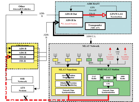
As shown in Figure 1, the pseudolite (PL) architecture allocates the position and integrity functions to the aircraft, similar to how GPS receiver-autonomous integrity monitoring works. The PL alternative would leverage all of the existing 1,100 DME facilities plus the planned ADS-B ground-based transceiver (GBT) facilities to provide a combined network of approximately 1,900 sites.
As shown in Figure 2, the PL architecture requires the GBT and DME sites to be synchronized to a common time standard so each facility can generate and transmit a heartbeat message consisting of the station identification and an accurate time stamp. The ADS-B in avionics would host the position calculation and integrity monitoring functions and pass this information to the aircraft navigation over a new interface, if GPS becomes unavailable.
Figure 2. Multi-lateration (MLAT) alternative block diagram.
The potential advantages of this alternative include a simpler architecture that does not require a ground system to compute the position of the aircraft. A common non-GNSS or robust GNSS time reference is required.
Straw Man Signal Design
The authors propose a straw man signal design for the broadcast of one-way ranging signals from existing DME transmitters. The goal is not to provide a final design for such a signal. They recognize that many modifications and improvements will be required to bring such a function to fruition. Rather, they offer the proposal as a catalyst for the community, and hope that it will serve as a starting point for a vigorous discussion on this critical topic.
Signal design is directed at these goals:
The new signals should be added to the existing broadcast from operational DME beacons without significant degradation to the two-way ranging accuracy provided by the DME beacon to legacy users. The new signals would overlay the existing replies that complete the traditional two-way DME transactions. More specifically, they could be implemented by triggering existing beacon with requests from a pseudo-aircraft located near the operational DME beacon. Thus, they hope to avoid any changes to existing ground hardware and by so doing realize benefit from the entire set of DME beacons in operation today.
The new signals should provide one-way ranging to modified avionics. The authors do not wish to modify the ground equipment, but recognize that one-way ranging from a DME station will require new avionics.
In addition to one-way ranging, the new signals should also support a modest data capability. This data would include the DME location, DME identification, time information, and a parity field to ensure data integrity. The proposal targets a data capacity around 150 bits per second, because similar capacity has served well for other one-way ranging systems such as GNSS and SBAS.
Finally, the new signal should also enable source authentication. The authors feel that signal authentication is needed, becau
se radio navigation may be subject to electromagnetic attack in the decades ahead.
The authors then describe and illustrate in seven figures the definition of a DME chip, a do-no-harm criterion, synchronization sequence, data field, data erasures and errors caused by competing channel traffic, data content, and source authentication. They indicate that they are looking at other signal alternatives for the DME band as well. These alternatives would make more liberal use of spread-spectrum technology.
Authors of the APNT study were Leo Eldredge (FAA), Per Enge (Stanford), Mike Harrison, Randy Kenagy, Robert Lilly (all with Aviation Management Associates), Sherman Lo (Stanford), Robert Loh (ISI), Mitch Narins (FAA), and Rick Niles (MITRE CAASD).
Our readers respond to the cover features in the April, May, and June issues: the two-part special the “Origins of GPS” and Richard Langley’s look at “GPS by the Numbers.”
Source: GPS World
Spilker and Parkinson: from GPS Origins to L5
Thank you so much, Brad, for the recognition you gave me in your history of GPS origins in the May and June issues.
I keep in my sometimes near photographic memory the numerous hours and trips we made over these many years, especially in the early days when you were Joint Program Director of GPS, the meetings we had with Bob Cooper and the Navy admirals. You
offered me the opportunity of a lifetime to contribute a little.
The one thing that you did not mention because of modesty is your ability to put together a team of Air Force officers so outstanding that I have not seen a comparable group anywhere else.
There is at least one other contribution worthy of inclusion, later in the program. One day during a board meeting at Stanford Telecom, I pointed out to Bill Perry that Congress had just zeroed out the GPS budget. He immediately got on the phone to the chairs of the House and Senate Armed Services Committee. Sam Nunn was chair for the Senate, and after much work and many calls, talked them into reversing that decision.
I have often thought that had the two parallel Navy Timation and Air Force 621B programs not been folded together as a single joint program, neither program would have survived.
On another subject, I think there is still work to be done on precision interoperability of multiple GNSS. How does it relate to “bounded inaccuracy” and integrity and precision positioning and carrier-phase precision?
Finally, many probably do not know it, and I have not received any recognition for it, but the work I did in designing the GPS L5 signal was performed as a gift to the U.S. Air Force, Federal Aviation Administration, and our country, with no compensation of any kind including my travel to the ION conference where I gave the award-wining L5 paper with AJ Van Dierendonck.
[See J. J. Spilker and A. J. Van Dierendonck, “Proposed New Civil GPS Signal at 1176.45 MHz,” Proceedings of ION GPS-99, Institute of Navigation, and an earlier, similar paper at the June 1999 ION Annual Meeting. — Ed. ]
Source: GPS World
I only mention it now because of the successful Block IIF launch. I ask nothing in return, and only hope it is of some value to our country and the world.
— Jim Spilker, Jr.
Half Moon Bay, California
Brad Parkinson replies:
Thanks to both you and AJ. It will be an outstanding addition to civil (and I hope military) options. Thanks also, of course, to the groups that ironed out the myriad of important details.
You also deserve credit for the initial work on split spectrum. Recall we suggested it for the civil signal to attain separation, and it was immediately endorsed and selected as the basis for the military L(M) signal.
— Brad Parkinson
Palo Alto, California
Selling GPS
Reading your two-part history of GPS origins recalled another story about those early years, and an influential Air Force officer.
Major General George Keegan was one of the most interesting people I met in my 35 years of Air Force civil service. Primarily an intelligence officer, he was considered one of the leading authorities on the Soviet Union, had been military attaché in the American Embassy in Moscow, and had just been given interim assignment as Director of Plans and Programs, HQ Air Force Logistics Command. He probably did not know anything about logistics, but he had a large staff to help him.
It was soon evident that he liked to come out to California, ostensibly to see his troops there (my office). What he really wanted was to go to the RAND Corporation in Santa Monica, the first non-profit brains factory set up in 1946 to guide the military services. RAND had a group of retired generals and admirals who war-gamed all sorts of scenarios to test various plans and to critique experiences leading to recommendations for changes. This was stimulating and valuable to him.
I was in charge of arranging his visits, and he was highly interested in the programs underway and especially in development at the Space and Missiles Systems Organization, where I worked. I would arrange briefings for him and occasionally drive him to our offices outside Norton Air Force Base near San Bernardino where the ballistic missile programs were developed.
We were collocated with the SAMSO Development Plans shop on the 4th floor of the Aerospace Corporation headquarters building when he called to set up a visit. He asked me what he had not been briefed on. I thought of one program, then called 621B, and told him it was a study area with a lot of promise. He asked me to set it up.
The “Program” was one lieutenant colonel in an office up the hall from us. He was managing several contracts to explore and develop the concepts for operation and conceptualize the hardware for development of what is widely known now as GPS.
The lieutenant colonel, whose name is lost to me, was not enthusiastic about briefing Gen. Keegan. I told him he was going to be on the Air Staff, he had security clearances for everything, and he would be smart to accommodate him. He agreed, but obviously reluctantly.
When General Keegan arrived, the lieutenant colonel started to describe the program as then projected. Gen. Keegan was obviously excited at what he was hearing, and he started throwing questions.
As a little background, knowing where you are precisely and being able to use that information is one of mankind’s oldest problems, and for the military forces, it is of the highest value. Among the many guidance systems in the inventory were Loran, OMEGA, TACAN, and many others. The annual costs to develop, maintain, improve, and operate these ran into hundreds of millions if not billions of dollars, and all of them operated with severe limitations.
General Keegan asked, if 621B were developed and deployed successfully, would it supplant and obviate the need for Loran? He got an extremely reluctant answer, yes. Would it replace TACAN? Same answer. OMEGA? Same answer.
I remember him sitting there staring at a very discomfited lieutenant colonel. He said, if I recall his words correctly, “Colonel, you don’t know what you have here. I don’t think you realize its importance. I will just have to sell it for you.” Later, when the General had left, the lieutenant colonel asked me if he was kidding. I replied that, from what I knew of him, he meant what he said.
Fast forward now about two years. General Keegan was the Intelligence Chief, HQ U.S. Air Force. Program 621B had progressed, had several people in the development planning process, and was ready to expand greatly if funding were provided by the Department of Defense. It was in competition with many other Air Force, Navy, and Army programs, and there wa
s no assurance that all would be approved.
At that time, possibly even today, there was an annual Department of Defense conference to allocate funds called the Defense Systems Acquisition Review Committee, or DSARC. Each agency presented its case. The 621B program chief was there (I now recall him to be Col. Parkinson, from reading the article), and he came to see us after the meeting in Washington. He was euphoric, and he wanted to know who General George Keegan was. I told him of the briefing I had arranged with his predecessor several years ago, and what Keegan had said. He said General Keegan had come through in spades.
This is second-hand reporting, but what happened was that before the DSARC began, General Keegan, who was not a member, asked the chairman for permission to address the group. What he said was something like this:
“Perhaps once in your lives, if you are extremely fortunate, you may have the opportunity to influence a development that may truly benefit your country. Today you have an opportunity to foster a program that will not only be of enormous value to all the armed services, but provide the answer to one of man’s oldest problems. Program 621B will give the military capabilities that will surpass anything ever imagined, and give the civilian world a spinoff of obvious immediate value and unlimited future potential. Whatever else is approved today, this program should be considered vital.”
The program director said General Keegan’s remarks were delivered with passion, and when he had finished and left their room, everyone looked at each other. He said their presentation was made easy — they were asked a lot of questions, and they had the opportunity to fully describe the timing, the impact, and the significance.
The result was they were not only fully funded, but they were told that if they could use more funds later, to let them know. He said after that speech, there was no question in anyone’s mind that there would be a wide open road for their program.
One of the rewards of my job in those years was being aware of and sometimes, in some way, involved in many fascinating events and programs. In this case, I inadvertently set in motion a chain of circumstances that, in a small way, may have facilitated the development of one of the most rewarding developments that came from the space and missile programs of the 1960s, ’70s, and ’80s.
I did not sell GPS, but, unknowingly, I helped.
— Don Hallwerck
Long Beach, California
Source: GPS World
Let Me Count the Waves
I read your publication with great delight but little understanding — with the possible exception of Mr. Langley’s contributions, especially “GPS by the Numbers” in the April issue. Fiddling with my calculator years ago, I quickly found pi to eight digits using 355/113. Do you suppose Mr. Langley has a better simple m/n?
— John Woodcock
Bellevue, Washington
Richard Langley replies:
Thanks for your message and kind words about GPS World. Fraction approximations to pi is an interesting topic, one that I didn’t have much room to write about in the numbers article. Your use of 355/113 as a good approximation for pi is one that has been known for awhile. It was first discovered by the Chinese mathematician, Zu Chongzhi in 480 A.D. It is good to seven digits. You need more than an 8-digit calculator to show this, though. Type 355/113 into the Google searchbox to get an answer to 9 digits and you’ll see that only the first 7 are valid. It’s somewhat more complicated, but the fraction 103993/33102 gives pi to 10 digits. These fractions can be derived from the continued fraction representation of pi. For a discussion of that and many other interesting facts about pi, see Wikipedia.
I have received the latest issue of GPS World. What a remarkable accomplishment! An outstanding example of sustainability, commitment, impact, and excellence! The Innovation column has constantly been a source of inspiration and ideas for all, not least GNSS students around the world.
If ever you have the chance to collate them in one single pdf file and put it on your website or/and that of GPS World, this would be a most valuable contribution and worth more than many books on the subject I can think of!
Congratulations, and may we see you on the front page for the 300th column!
— Gerard Lachapelle
University of Calgary, Canada
Just read your “Numbers” article. I enjoyed it very much, especially because I am writing java code for an SDR-GPS-receiver I am building. As a starter I am trying to decode Kai Borre’s data file. I just finished implementing parallel code search using FFT. Gives remarkable insight in DSP. I am a retired engineer and radio amateur PA1KDG. Keep on writing and I’ll keep on reading — promise.
— Kees de Groot
Wageningen, The Netherlands
Richard Langley replies:
Many thanks for your message and interest in the GPS World Innovation column. Coincidentally, one of my students has just finished up a Ph.D. project on designing a strategy for implementing a SDR-GPS receiver and presented his results in April. Good luck with your project.
I started my relationship with GNSS and Moore’s Law in 1985, writing software for GPS tracking loops on the Advanced Range Instrumentation Aircraft program at the Applied Physics Laboratory of Johns Hopkins University for the U.S. Air Force. The project’s purpose was to navigate a large jet to accurately fly a pattern to drop buoys into the ocean. That receiver had seven circuit boards (six trackers and one navigator) mounted on a VME backplane in a 19-inch rack mount in the back of a C-130, and was about the size and weight of suitcase.
In 1988, I helped design and build a single-board Swordfish receiver at Stanford Telecom that went into a two-man portable pseudolite for Trident missile testing. This was considerably smaller and lighter: about the size and weight of a desktop computer. Moore’s law — which, by the way, states that the number of transistors that can be placed inexpensively on an integrated circuit doubles approximately every two years — helped mostly by allowing much better CPUs and memories so we could put it all on a single board. I actually carried this beast off a landing ship tank (LST) onto a small island in the South Pacific called Kwajalein.
With Moore’s law in full swing in 1990, I moved to the commercial sector at Trimble Navigation and worked on the NavTrac, a lunchbox-sized complete GPS receiver for marine navigation, and then onward to timing receivers and eventually credit-card-sized modules. It became clear that Moore’s Law was a great friend of GNSS and was going to enable a whole new slew of applications by moving from the board level to the chip level.
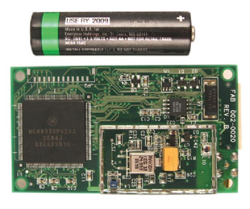
I went to SiRF Technology, Inc., very soon after it was founded in 1995, to help develop the first commercially successful GPS chipset, the SiRFstarI (see photo).
Photo: SiRF Technology, Inc.Photo: SiRF Technology, Inc.
SiRFstarI-based module, both sides, with representative AA battery to scale.
You can see that this module still had separate chips for the CPU, flash, SRAM, GPS correlator chip, the GPS RF ASIC, and a lot of other components.
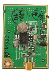
Last year, we introduced the SiRFStarIV architecture and the GSP4e chip. The module made from this chip has the same basic functionality (RF in, position out) but at a much higher performance level in terms of sensitivity, time to first fix, accuracy, and much lower power consumption. The photo at right shows a 4e module. Also note how few external components are required.
SiRF 4e module. A hearing-aid battery shows scale and represents the relative power requirements of this module. Photo: SiRF Technology, Inc.
To really understand the impact of Moore’s law on GNSS today, we have to break down the impact on the various parts of the receiver. The measurement of each section (area, power, or bytes) was then normalized to a starting point of 100 in 1995. The time span of 14 years is about seven Moore’s law doublings (every 2 years), producing an expected decrease of 1/128. We can see that the power and digital silicon area have tracked very well over that time period. However, it is also apparent that RF has not even come down by half in that time frame (although it has swallowed a lot of external components as seen in the pictures) — and the code size (ROM + RAM) has grown by 2.5 times.
This has turned Moore’s law into a bit of a foe in the current timeframe, as the costs associated with silicon products are clearly known to customers (die size is easy to measure) and has driven the prices for GPS receiver downwards accordingly. However, as one can see, more and more software is needed to enable the new features and functions, and with dropping prices due to decreased silicon size, it becomes harder and harder to pay to feed all the hungry engineers here at CSR. This is the crossroad at which our segment of the industry has arrived: how do we continue to add innovation and still make a profit selling silicon when Moore’s Law is not helping anymore? I am not sure I know the answer yet, but we have a lot of good ideas that we are working on.
Most of these ideas come from expanding the notion of location determination to extend beyond using just GPS and its currently available augmentations. Adding support for other GNSS constellations requires more hardware; the amount is highly dependent on which constellation(s) we are talking about. GLONASS, because of its different frequency, requires more RF silicon, requiring more total area because the existing area is not shrinking as fast. Galileo and COMPASS will require more digital area for their complex coding schemes, but these can be more easily handled with shrinking process geometry. All will require significant software effort to bring in new acquisition schemes, tracking loops, and navigation algorithms.
But location determination will not be a GNSS-only problem for much longer. Hybrid navigation using other signals of opportunity and MEMS sensors will play a large role in expanding the ability to provide accurate location to consumers wherever they go. The integration of these technologies into a coherent location determination system is a large software effort, and one that CSR has been working on for years in automotive applications.
Clearly, the need for accurate location continues to grow in consumer devices. At CSR we feel we are in the best position to deliver that, with or without help from Moore’s law.
Greg Turetzky is senior marketing director for SiRF Technology Inc., a member of the CSR Group of companies.
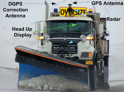
A virtual reference station network covering a metropolitan area supplies position corrections to commuter buses equipped with a driver-assist system to enable safe operation, even under harsh weather conditions, along high-volume roadways.
By Craig Shankwitz
Bus-only shoulders on major traffic arteries enable a bus to travel on typically unused road right-of-way, bypassing congestion during peak rush hours. As the shoulder is typically only centimeters wider than the bus itself, lane-keeping becomes a key factor, and is accomplished in a pilot Minnesota project using dual-frequency, carrier-phase differential GPS (DGPS) as its primary positioning technology. DGPS provides position estimates accurate to 5–8 centimeters at a rate of 10 Hz, and is used to determine vehicle position and heading. An on-board map database is used to determine the position, orientation, and trajectory of the vehicle relative to the roadway.
Use of the shoulder as a busway offers several construction and operational advantages:
Ease of Implementation. The shoulder exists; there is no need to acquire and develop additional right of way.
Low Costs. The cost to strengthen and modify an existing road shoulder is significantly less than constructing a new busway.
Routing. Because bus-only shoulders follow existing routes, no changes to bus routes, bus stops, or transit stations are needed to support bus-only shoulder operations.
Customer Satisfaction. Transit customers who travel on buses that use a bus-only shoulder perceive a travel-time saving two to three times greater than actually realized. Keeping the bus moving at all times offers a significant psychological advantage.
Increased Ridership. A 1997 study of bus-only shoulders in the Twin Cities analyzed more than nine bus-only shoulder routes for two years and found a 9.2-percent increase in ridership along these routes. At the same time, total ridership had decreased by 6.5 percent.
However, the use of bus-only shoulders imposes additional stress and strain on a driver. The narrow bus-only shoulder leaves a driver very little margin of error. Operating within this small margin is difficult even during the best traffic and weather conditions, and degrades to nearly impossible during heavy traffic and poor weather conditions, which are frequent during Minnesota’s notoriously hard winters.
During difficult weather and traffic conditions, the use of the bus-only shoulder offers its greatest transit advantage. If a driver is unable to utilize the bus-only shoulder, this advantage is lost. A properly designed and executed driver-assist system (DAS) enables a driver to use the shoulder under all conditions, thereby increasing schedule adherence and, as a result, rider satisfaction.
Under the U.S. Department of Transportation’s Urban Partnership Agreement, the University of Minnesota’s Intelligent Vehicles Lab (IV Lab) and HumanFIRST program, the Minnesota Valley Transit Authority (MVTA), and Schmitty and Sons Transportation will soon deploy DAS on 10 Gillig low-floor transit buses. These buses will provide express service between Apple Valley and downtown Minneapolis, a 22-mile, one-way trip.
Driver-Assist History
The IV Lab has developed and deployed DGPS-based DAS since 1995. The first deployment on public roads occurred in 2001, as part of the DOT’s Intelligent Vehicle Initiative Generation Zero Field Operational Test. The DGPS-based lane-keeping assistance was integrated with forward-looking radar for collision avoidance, enabling safe vehicle operation in zero-visibility conditions.
Two separate deployments took place in Alaska. The first occurred in 2003 with a snowplow and a snowblower which clear the Thompson Pass on the Richardson Highway. These vehicles are still in use. Because of this success, the State of Alaska installed the DAS in two more vehicles at Deadhorse Airport.
During the summer of 2010, the two original Thompson Pass systems will be upgraded with new computational hardware, and three new systems will be installed on three new highway maintenance vehicles. The value of the driver-assist system has been proven, and those who use it have grown to rely on its all-weather capabilities. It has functioned reliably for seven years in extremely harsh conditions.
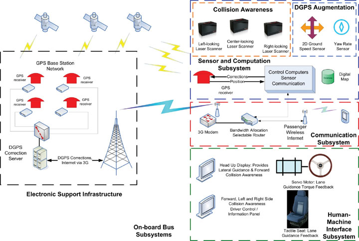
The DAS provides two primary capabilities for transit applications: lane-keeping and collision awareness. The system provides assistance only; a driver is always responsible for control of the vehicle. Figure 1 shows the components comprising the DAS.
Figure 1. Complete driver assist system component schematic, showing both infrastructure-based and vehicle-based components.
DGPS-Based Lane-Keeping. The primary positioning sensor used aboard the buses is a dual-frequency, carrier-phase GNSS receiver, providing centimeter-accurate position measurements at 10 Hz. With the exception of the DGPS augmentation system described later, all other DAS system processes are synchronized with the arrival of DGPS position updates.
Realtime CMR+ DGPS corrections are provided over the 3G cellular network from the IV Lab VRS network. The IV Lab VRS network is based on six receivers located around the perimeter of the Twin Cities Metro area. These six receivers are connected via landlines to a server system located in the IV Lab at the University of Minnesota, running GPSnet and RTKnet applications. To ensure GPS correction reliability, an integrity manager software issues alerts for both short-term and long-term aberrations in the data provided by the six base stations. This ensures accurate corrections are sent to the buses using the narrow shoulders.
The onboard receiver also plays a crucial role in accurately estimating vehicle body heading. In rural applications where GPS augmentation is unnecessary, GPS velocity heading estimates provided directly from a GPS receiver serve as a sufficiently accurate body-heading estimate. However, in GPS-denied environments where an augmentation system is needed to provide accurate position and heading estimates when GPS is lost, velocity heading from an onboard receiver is an insufficiently accurate estimate of vehicle heading. To support such navigation, the IV Lab developed a technique, described later, by which body heading can be estimated with errors less than 0.1 degree.
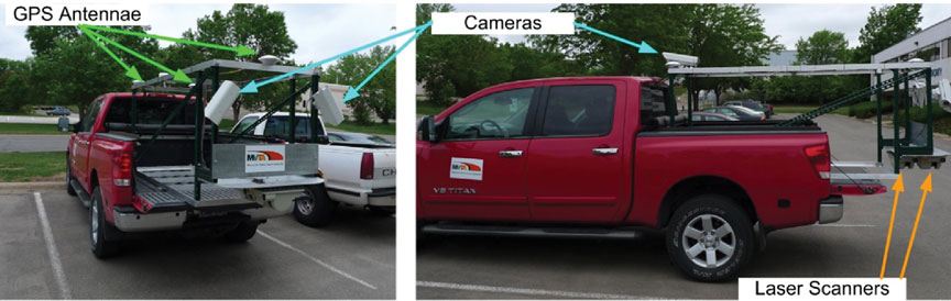
IV Lab mapping rig installed in a pickup truck: three dual-frequency, carrier-phase DGPS receivers; two laser scanners, one measuring retroreflectivity, the other road crown and rutting; and forward and sideview cameras, to help analyze anomalous data.
Map Databases
Lane-keeping uses DGPS with an onboard map database describing the location and type of lane boundaries and other relevant roadway elements to an accuracy of approximately 10 centimeters. These map databases can be constructed in one of three ways:
from sufficiently accurate photogrammetric data,
by driving centerlines and using known road-construction standards to d
etermine the location of lane boundaries and other relevant elements relative to the lane centerline, or
by using a combination of laser scanners, DGPS receivers, and cameras to determine the global location of the reflective markings that bound lanes and shoulders.
Lane-keeping information is continuously provided to the driver; lane-departure alerts and warnings use a comparison of vehicle speed and heading to the map database to determine when alerts and warnings should be issued.
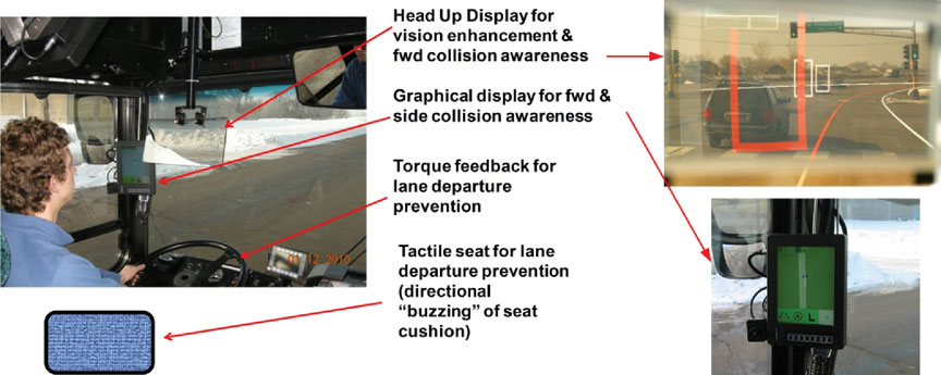
The alerts and warnings are provided via a multi-modal human-machine interface (HMI), illustrated in Figure 2, through three modes:
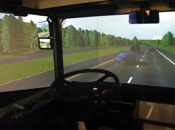
graphically, through a head-up display (HUD) that gives a virtual view out the windshield when environmental conditions limit visibility;
haptically, through a torque-actuated steering wheel giving a restorative torque on the steering wheel in the event of lane drift; and
tactically, through a seat equipped with actuators that vibrate on the side of the seat to which the lane is being departed.
Figure 2. Multi-modal driver interfaces. Left: Graphical, haptic, and tactile feedback modes provided to the driver. Upper right: View through the head-up display. Graphical lane departure alert indicated by left shoulder boundary colored red, collision awareness alert (white rectangles), and collision awareness warning (red rectangle). Lower right: Forward, left, and right side collision awareness information presented on the display on the left “A” pillar.
Lane-departure warnings come in stages. As the vehicle-trajectory estimator determines that the likelihood of a lane departure is sufficiently high, a lane-departure warning is issued to the driver through the HUD: a change in lane boundary color from white or yellow to red. Should the driver contact the lane boundary, a seat-based warning is activated; the side of the seat corresponding to the direction of lane departure vibrates, warning the driver. If the driver fails to respond to these two stimuli and continues past the lane boundary, the steering motor torque is applied. This multi-stage approach captures the drivers’ attention, but if they respond in a timely fashion, their annoyance is limited.
The torque applied by the steering servo motor is limited, and cannot deliver sufficient control action to autonomously steer the vehicle. This is by design; the driver is responsible for operating the bus. The level of torque applied to the steering wheel is analogous to an automotive front-end misalignment; it is sufficient to capture the drivers’ attention, but not to steer a bus off the road.
Forward-Collision Awareness. Sensing for forward-collision assistance is provided by a front bumper-mounted multi-plane scanning LIDAR sensor. Forward-collision alert and warning information is provided in two stages to the driver through the HUD. As now configured, if the obstacle detected is in the present shoulder of travel, the obstacle is represented as a red, open rectangle, with red indicating a warning status. If an object is located in an adjacent lane, the obstacle is represented as a white, open rectangle, with white indicating an alert status.
Obstacle-detection processing is enhanced by the presence of the onboard map database used for lane-keeping. Obstacle target information provided by the LIDAR sensor includes range, range rate, and azimuth angle to the target. The bus position and heading is provided by either DGPS or the DGPS augmentation system. Through a coordinate transformation, LIDAR information in the vehicle coordinate frame is transferred to the global coordinate frame. This allows the LIDAR target to be placed on the map database; if the target is in the vehicle lane of travel, it can be considered a threat, but if the LIDAR target is not in the same lane as the bus, then at that time the target is not a threat to the driver.
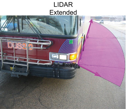
Side-Collision Awareness. Side collision awareness is enhanced by multi-plane LIDAR scanners mounted on on the front bumpers on both the left and right sides of the bus, and connected to a pneumatic actuator.
Side-collision awareness information is provided to the driver via an LCD panel mounted on the left front A-Pillar (see Figure 2). This display is touch-sensitive, and can be used by the driver to log in (only certified, trained drivers can operate the system) to select feedback modalities (choose any or all of the available feedback modes) and to check system status.
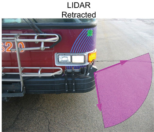
SIDE-MOUNTED LASER SCANNER used for both side-collision awareness and DGPS augmentation. When extended, the LIDAR scans 100 degrees of the horizontal plane. One boundary of the scanned plane points behind and runs alongside the bus; the other boundary points forward of the bus by approximately 10 degrees.SIDE-MOUNTED LASER SCANNER used for both side-collision awareness and DGPS augmentation. When retracted (right), the LIDAR points in the direction of the ground, and can be used for curb-following when DGPS is unavailable.
Suburban and Urban
Although the rural implementation of the DAS operates in extremely harsh weather conditions, these implementations are technically less problematic than suburban and urban implementations. In rural applications such as the snowplows, DAS-equipped vehicles typically operate with a single occupant in a small geographic area, travel on relatively low traffic-volume roads, and enjoy a clear view of the sky. Suburban and urban applications carry passengers, operate across a wider geographic area, travel on high-volume roads, and suffer from periods where view of GPS satellites is either partially or completely blocked.
These operational differences require substantial changes to the DAS subsystems for urban/suburban use.
DGPS Base Stations. In rural areas, DAS-equipped vehicles typically operate over a relatively small geographic area; a single GPS base station will provide adequate coverage as the maximum baseline between rover and the base station remains less than 25 miles. Suburban applications cover a much wider area, and a network of DGPS correction stations is needed to keep baselines low.
For the UPA project, the IV Lab operates a six-station virtual reference station (VRS) network. This network covers the greater Twin Cities Metropolitan area, and supplies compact measurement record (CMR) corrections to each DAS-equipped bus. Satellite observables are sent from each base station receiver to both the VRS server at the IV Lab and to a VRS server at the Minnesota Department of Transportation.
Broadcast of DGPS Corrections. In rural areas, the DAS system has served to keep roads passable in inclement weather conditions. This has been viewed as a safety application, and as such either UHF or VHF channels in the public safety bands have been used to broadcast DGPS corrections. In urban areas, no single UHF or VHF frequency is available to cover an entire metropolitan area. Therefore 3G cellular data communications are used to provide DGPS corrections to DAS-equipped vehicles.
Use of 3G cellular data communications brings the transit customer an added benefit: free Wi-Fi. The provision of DGPS corrections, using the CMR+ correction format, requires approximately 10 Kbit/second. This bandwidth is assigned high priority by the onboard router. The remaining 700 Kbit/s of 3G bandwidth is made available, at a lower priority, to bus passengers. On an express route service, passengers can e-mail and surf the web on their daily commute, making productive use of
time that might otherwise be lost.
The VRS server provides a unique correction to each DAS-equipped bus. Communication between the bus and the VRS server is initiated by the bus when it sends its coarse (uncorrected) position to the server. The server replies with a correction optimized for that coarse location. Corrections are sent at one-second intervals. Every two minutes, the bus sends its current position, and the VRS server responds with corrections optimized for that new location. With this scheme, the baseline between the VRS and the roving bus is never more than two miles. The two-mile limit maintains position accuracy without consuming excessive wireless or computational bandwidth.
DGPS Redundancy. In rural applications, the view of the sky is generally unobstructed, and FCC licenses provide adequate effective radiated power from the DGPS base stations. This assurance of access to both satellite and corrections signals generally suffices to support uninterrupted vehicle positioning. Both base-station and onboard GPS hardware have proven to be robust and reliable. With these local operating conditions, public agencies have found no need to augment DGPS for rural applications.
Suburban and urban applications, however, require an augmentation system to support DAS operation when DGPS is unavailable due to outages caused by overpasses, overhead road signs, tree canopies, and so on. Passenger safety and the need to provide reliable schedule adherence require that positioning be provided even when DGPS is unavailable, by a vehicle-based DGPS augmentation system.
Vehicle-Based Augmentation
The vehicle-based augmentation system (VBAS) uses direct measurements of ground velocity, a measure of vehicle yaw rate, and an accurate estimate of the vehicle position and heading at the time DGPS is lost to estimate vehicle position and heading for the duration of signal loss.
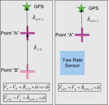
A commercial off-the-shelf sensor designed for measuring vehicle and/or tire slip measures vehicle 2D velocity. Yaw rate can be measured either with an inertial rotational rate sensor or a second 2D velocity sensor. Yaw rate measured using a pair of these 2D sensors eliminates the rate bias and rate bias drift associated with inertial sensors. Figure 3 shows both configurations.
FIGURE 3 Two approaches to VBAS to mitigate DGPS outages. The diagram on left shows implementation with two 2D velocity sensors to determine vehicle yaw rate. Computationally, this is attractive as senor drift need not be considered. The diagram on the right shows an implementation with one yaw rate sensor, and one 2D velocity sensor. This is the configuration operating for the UPA; it requires yaw rate sensor drift compensation to provide accurate measures of vehicle yaw rate.
An accurate measure of vehicle heading at the time GPS positioning is lost is critical to the augmentation process. A performance goal of 20 centimeters tolerable error at the end of a 15-second outage for a vehicle traveling at 25 miles per hour (11.2 meters/second) requires a heading estimation error of no more than 0.07 degrees (that assumes the only source of error is attributable to the heading).
GPS outages (time from loss of position to reacquisition) attributed to passing under overpasses range from 7 seconds (single bridge) to 9 seconds (double bridge). The IV Lab augmentation system reliably provides sufficiently accurate position and heading estimates to carry through these outages. At the present level of performance, should an outage last more than 15 seconds, the accuracy of the augmentation system cannot be guaranteed. In this event, the driver is alerted, and the DAS is deactivated until a DGPS position fix is reacquired. Fortunately, since new receiver firmware was installed, no instances of an outage exceeding 15 seconds have occurred during two months of test, evaluation, and driver training.
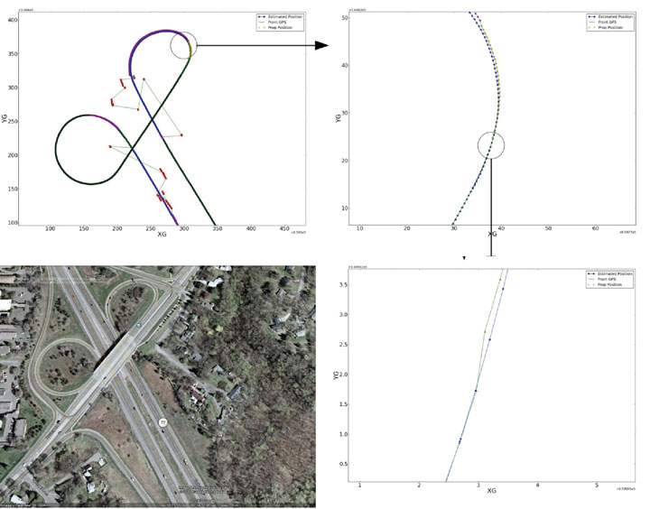
Figure 4 illustrates the accuracy of the VBAS system. At the time the fix solution is reacquired on the exit ramp, the lateral error between the fix solution and the position estimated by the VBAS is approximately 10 centimeters. This accuracy is sufficient to allow a driver to travel on the entrance ramp even during zero-visibility conditions.
Figure 4. Example of VBAS as a bus operates on the Cedar Avenue/Old Shakopee Road overpass. Bus trajectory is northbound on Cedar, exiting westbound Old Shakopee Road, then entering southbound Cedar Avenue from Old Shakopee Road. Upper left shows northbound trajectory and loss of satellite lock. Upper right shows reacquisition of DGPS, float, and fix states of the DGPS receiver. Lower right shows accuracy of VBAS system compared to DGPS when DGPS reacquires fix. Lateral error of VBAS at at the time the fix is reacquired is approximately 10 centimeters. Lower left shows satellite view of the interchange.
Driver Training
Bus-only shoulder operation has proven itself safe and, in fact, safer than normal transit operations, according to recent data. The goal of driver training is to prepare drivers to use the DAS system to enable them to safely use the bus-only shoulders in conditions under which they normally would not.
A rigorous training protocol developed in cooperation with the University of Minnesota HumanFIRST program, Schmitty and Sons Transportation driving instructors, and MVTA involves both simulator-based and on-road training.
Simulator-Based Training
Beefore using driver assist systems, bus drivers are continually taught that the driver controls the bus and is responsible for both the passengers and vehicle. Drivers take this responsibility seriously, and as such, develop skills and techniques that guarantee safe passage under all conditions, even when running on narrow, bus-only shoulders.
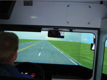
To best prepare drivers for using the DAS under difficult conditions, a high-fidelity driving simulator was commissioned. A DAS was installed in the simulator, and an interface to the simulator was created. In this context, a driver has the ability to train in normal and abnormal (low to zero visibility) conditions before beginning on-road DAS training and use.
In the simulator, the driver learns that the system only provides assistance; responsibility for the safety of the bus and passengers still resides with the driver. Experience with Alaskan snowplow operations, where formal training is limited to a few on-road test drives, has shown that a driver may take a few winter seasons to fully accept the system. This delayed acceptance is in part attributable to the fact that for six months per year a driver has no opportunity to train with the system. Acceptance gained over one winter season is lost during the summer.
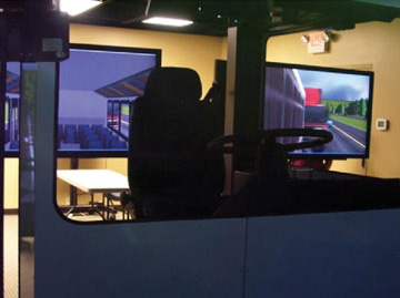
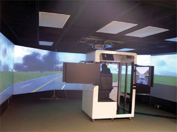
The simulator installed at an MVTA bus garage uses a seat-based motion platform to achieve realistic vehicle dynamics. The DAS installed in the simulator allows a driver to train in all weather and traffic conditions on a geospecific roadway before transitioning to a DAS-equipped bus. Geospecificity is achieved through the creation of virtual worlds based on roadway data collected by the mapping vehicle shown earlier.
Bus-driving simulator at the MVTA bus garage in Burnsville, Minnesota.Bus-driving simulator at the MVTA bus garage in Burnsville, Minnesota.Bus-driving simulator at the MVTA bus garage in Burnsville, Minnesota.Bus-driving simulator at the MVTA bus garage in Burnsville, Minnesota.
On-Road Training
After a driver both demonstrates an
d acknowledges comfort and competence with the DAS in the simulator, training transitions to the actual route on which the buses will operate. Each of the 10 buses is equipped with a six-camera data-acquisition system. The six cameras capture not only the driver’s actions (hands, face, feet), but also views of the road (front, left, and right sides.)
Drivers travel with an instructor. The onboard data acquisition system can be used to reconstruct particular scenarios as a means to offer advice as to how the driver and system can better interact in difficult driving and traffic conditions.
On-road training benefits system developers as well. Training offers a driver an opportunity to test the system in real-time on an actual road. The perspective a driver brings is generally different than that of the developer, and the insights the end user provides typically produce a better system. As an example, driver experience with the system during the initial training period produced the staged approach to lane-departure alerts previously described.
Conclusion
The IV Lab, MVTA, and Schmitty and Sons Transportation will soon release 10 DAS-equipped buses into revenue service to support narrow bus-only shoulder service between downtown Minneapolis and Apple Valley, Minnesota. Although the IV Lab has deployed a number of DAS-equipped vehicles, this UPA deployment represents the first time that the system has been used to transport passengers. This deployment should prove that although DGPS systems are susceptible to periodic outages, a properly designed and executed augmentation system will provide a sufficiently robust system that will be accepted by both drivers and passengers. It will also demonstrate to other transit agencies that even narrow rights of way offer significant transit advantages at low cost, and that potential operational difficulties can be overcome through the use of DAS technologies.
Manufacturers
The buses carry Trimble R7 receivers and Ibeo Lux multi-plane scanning LIDAR sensors. The IV Lab VRS network is based on six Trimble NetR5 receivers. The server runs Trimble’s GPSnet and RTKnet applications, with the Trimble Integrity Manager.
Craig Shankwitz is the director of the Intelligent Vehicles Laboratory at the University of Minnesota.
By Jürgen Rossmann, Petra Krahwinkler, and Markus Emde
Modern machines such as wood harvesters can automatically cut trees and remove branches, but an expert is still needed to plan a thinning and to mark the trees to be felled. The process can be accelerated if the forest ranger can virtually mark trees to be cut, using geographic coordinates instead of colored crosses sprayed on the stems. This requires the robotic wood harvester to be able to locate itself accurately to enable automatic navigation to the next tree for cutting.
Absorption of the GPS signal in the forest canopy leads to poor results, however, with errors up to 50 meters and more. Furthermore, the canopy may cause interruptions and signal loss for several seconds. The performance can be even worse on a moving vehicle, where the signal may even get lost until the vehicle reaches an open area or stops.
Other approaches use differential GPS (DGPS) sensors as their main source of position information. However, our experiments using a high-precision DGPS sensor showed that its accuracy is not even close to sufficient for navigating to a single tree. As the DGPS suffers from the same canopy-related disturbances and shielding, it cannot benefit from its theoretical advantages. In pratice, the DGPS system did not update its position at all when signal reception became too weak.
A different approach was needed. We found it in the framework of the Virtual Forest, more precisely in the semantic modelling of forests, where techniques are being developed to delineate single trees from remote sensing data, such as airborne laser scanner data. Along with the trees and their geo-coordinates, the height and the diameter at breast-height are determined. This data can be used to generate a tree map, which can be used for navigation. The map has a mean error between 0.5 and 1.5 meters, which is still below the mean tree distance of about 2.5 meters.
Visual GPS. The idea of Visual GPS is to bring current developments in the field of robotics into the forest and combine them with information on forest inventory so that the result outperforms other navigation approaches. A matching algorithm is run based on a tree map, generated from remote sensing data, and the tree group, which was detected by one or more laser scanners.
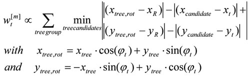
We then implemented a particle filter algorithm, as it enables considering different kinds of distributions. Particles are also called random state samples, and each particle is a hypothesis as to what the true world state might be.
In the initialization, particles are distributed uniformly. An importance weight wt is calculated for each particle, incorporating the measurements as described below. A sampling step rejects particles with a low importance weight and replaces them with new particles, which are distributed according to the previous map. This process is repeated until the particle distribution concentrates at one point, and the particle with the highest weight is returned as the result (see Figure 1).
Figure 1. Particle concentration after resampling; wood harvester at center.
A single tree as a landmark cannot be associated with its corresponding tree in the map. However, patterns of tree positions can be matched. We chose a square area to guarantee even particle distribution and short calculation time. Each particle represents a hypothesis for the position of the vehicle and is tested for its probability to represent that position.
To make the approach more robust against faulty tree maps, we implemented a rotation variant approach, determining vehicle heading along with its position. This enhanced the probability measure used in the propagation step. Instead of embracing only the distances of the trees to the reference point, their relative position is used, considering the heading wt of the current particle:
This approach directly calculates vehicle heading, but the sensitivity towards rotation, which results from the new probability measure, leads to a higher number of particles that must be used during the initialization step.
Global Search. Experiments on a test area with about 22,700 trees proved that the algorithm worked reliably for tree groups containing 20 or more trees, and for position errors of the magnitude of the mean tree distance. Similar tree groups could not be found within the forest. However, the calculation time was too long to be used for navigation.
Local Search. To overcome the high calculation time, we reduced the number of particles. The initial position is estimated with an ordinary GPS sensor. Although the GPS measurement is faulty in the forest, it can limit the search to a restricted area. Machines most often start at the edge of a forest stand, at a forest road, or a canopy opening. At these spots the canopy usually is transparent, and GPS sensors work with higher precision. Therefore, they provide a good initialization for the algorithm.
Robotic wood harvester.
In the following steps, the previous position can be used instead of the output of the GPS sensor for determining the search area. The previous position provides a better initial pose estimation than the GPS sensor and therefore gives the opportunity to further decrease the search area.
To reduce the number of trees for which the distance has to be calculated, trees with a distance from the initial pose estimation smaller than the sum of the estimation of the maximal position error and the maximal distance of the trees in the scanned tree group from the reference position are extracted from the tree map.
Another way to reduce the search area is to estimate vehicle orientation. This is difficult for machines such as wood harvester, which moves slowly and stops frequently when cutting trees. Therefore, small lateral position differences result in large orientation deviances, as the difference vector does not directly point into the direction of the movement any more. Another approach is to use sensor fusion and mount a compass onto the vehicle. During particle initialization, the angle can be restricted to the domain of uncertainty around the compass orientation. However, mounting a compass onto a wood harvester proved to be a serious problem, as the harvester’s massive metal body disturbs the compass measurement.
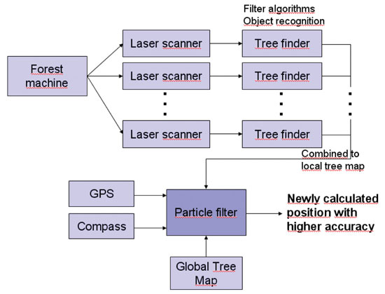
Figure 2 shows the workflow of the complete system.
Figure 2. Navigation system components.
Results
The simple criterion presented here proved to be reliable in the vast majority of cases. Problems can occur when the tree group contains trees that are not part of the tree map (false positive). This can happen due to missing trees in the tree map or faulty tree cognition in the local laser scanner measurement. In the first case, the understory might not have been detected in the airborne laser scanner data. In the second case, other objects like the harvester’s aggregate might have been mistaken for a tree.
The case of trees not detected in the local laser scanner measurements but contained in the tree map (false negative) does not create problems in the pose estimation step. The algorithm searches for a corresponding tree for each unit in the tree group. For a false positive, no corresponding tree can be found, whereas a false negative is simply not considered. However, if the size of the tree group is too small, the estimation errors grow. The minimum number of trees depends on the search area radius. A size of 20 trees proved to generate reliable pose estimations even during the global search. Dropping below 15 trees, the number of faulty position increases rapidly as more similar patterns can be found.
Single faulty positions can be filtered with respect to the movement constraints of a harvester. The velocity is very low, and the orientation cannot jump. In the experiments, cycle times of about 0.5 seconds were reached on a standard PC. As forest machines do not demand very short calculation time, the algorithm proved to run fast enough to allow identification of single felled trees onboard real machines. One application of the algorithm was to support a navigation assistant to the next tree, similar to navigation systems in cars.
To evaluate system accuracy on a real wood harvester, a surveyor’s office was instructed to measure the vehicle’s position at seven distinct locations. At each position, the sensor input data was written to file for several seconds. This data was evaluated, and for each location more than 45 pose estimations were calculated. The mean value of the position error amounted to approximately 0.55 meters.
Future Work
Reliability can be enhanced by using a detailed digital ground model and the cabin tilt in order to detect the area where the laser beams hit the ground, and therefore avoid the detection of false positives. Similarly, the position of the aggregate, which can be measured by integrating sensors in the hydraulic cylinders of the crane, can be cut from the laser scanner measurements and ignored during tree detection, further reducing the amount of false positives in the tree group. With the integration of an outlier rejection step for false positives in the detected tree groups that ignores trees for which no corresponding candidate tree can be found, a more accurate importance factor can be calculated.
Another task is the integration of the algorithm with a Kalman filter to allow real-time performance of the algorithm. Therefore, the Kalman filter is initialized with the pose estimation of the particle filter algorithm, which is also used for continuous checks of the current position estimate, thereby combining two algorithms with different advantages. The Kalman filter allows real-time execution and therefore speeds up the overall navigation algorithm. The particle filter algorithm can periodically check the position estimated by the Kalman filter and correct it. Furthermore, it provides a strong method to cope with two main problems in mobile robotics: the data association problem and the kidnapped robot problem.
Simultaneously, a mapping and map-correction algorithm could be integrated into the system so that understory trees, which cannot be detected using remote sensing data, and deciduous trees, which are more difficult to delineate in airborne laser scanner data, can be added to the tree map.
Jürgen Rossmann is head of the Institute of Man-Machine Interaction at the RWTH Aachen University, where Petra Krahwinkler and Markus Emde are research scientists.
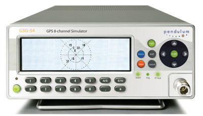
Spectracom’s new 8-channel GPS constellation simulator, the Pendulum GSG-54, provides a wide-range of capabilities for in-line production testing of devices integrating GPS receivers due to its ease-of-operation and fast test cycles. Its versatility also supports engineering organizations’ efforts for integrating GPS receivers into devices under development.
The Pendulum GSG-54 simulates the satellite signals detected by a GPS receiver. It comes in a bench-top chassis that is compact and portable. It offers built-in standards-based test scenarios that can be initiated or modified on the fly from the intuitive front panel interface, and offers a variety of connectivity options to control and reconfigure test parameters.
The GSG-54 GPS constellation simulator builds on the features available from Spectracom’s GSG-L1 single-channel GPS signal generator that offers simple but fast assembly verification for functions such as antenna connectivity, receiver operation, or satellite signal identification. The GSG-54 provides for many more test cases due to its ability to simulate eight different satellite signals to test position accuracy, sensitivity to loss of satellite signals, timing accuracy, and dynamic range. It can simulate movements and user trajectories, multi-path scenarios and various other atmospheric conditions.
Spectracom’s new 8-channel GPS constellation simulator, the Pendulum GSG-54, provides a wide-range of capabilities for in-line production testing of devices integrating GPS receivers due to its ease-of-operation and fast test cycles, according to the company. Its versatility also supports engineering organizations’ efforts for integrating GPS receivers into devices under development.
As more and more electronic devices integrate GPS receivers, manufacturers require instrumentation to fully test the GPS capabilities of each device on the manufacturing floor. According to Staffan Johansson, Spectracom product manager, “We understand the need for high-throughput manufacturing testing of GPS receivers. A multi-channel GPS simulator must be easy to use, yet powerful enough to confirm each device’s performance under a variety of real-world conditions.”
The Pendulum GSG-54 simulates the satellite signals detected by a GPS receiver. It comes in a bench-top chassis that is compact and portable. It offers built-in standards-based test scenarios that can be initiated or modified on the fly from the intuitive front panel interface, and offers a variety of connectivity options to control and reconfigure test parameters, Spectracom said.
The GSG-54 GPS constellation simulator builds on the features available from Spectracom’s GSG-L1 single-channel GPS signal generator that offers simple but fast assembly verification for functions such as antenna connectivity, receiver operation, or satellite signal identification. The GSG-54 provides for many more test cases due to its ability to simulate eight different satellite signals to test position accuracy, sensitivity to loss of satellite signals, timing accuracy, and dynamic range. It can simulate movements and user trajectories, multi-path scenarios and various other atmospheric conditions.
“Like our other products, the GSG-54 offers the lowest cost of ownership for manufacturers and development engineers by providing complete testing of multi-channel GPS performance with high throughput and ease-of-use without unnecessary complexity or expense,” said Lisa Withers, president and CEO of Spectracom.
The U.S. Army’s Autonomous Platform Demonstrator, or APD, is a 9.6-ton, six-wheeled, hybrid-electric robotic vehicle currently undergoing developmental and mobility testing at Aberdeen Proving Ground, Maryland. According to an Army statement, the demonstrator vehicle represents the state of the art in unmanned ground vehicle mobility technology.
With its advanced hybrid-electric drive train, the 15-foot-long vehicle, being developed by the U.S. Army Tank Automotive Research, Development and Engineering Center (TARDEC), can achieve speeds of more than 50 mph.
When equipped with its autonomous navigation system, the APD is configured with GPS waypoint technology, an inertial measurement unit and computer algorithms which enable it to move autonomously at speeds up to 50 mph while avoiding obstacles in its path.
“The vehicle has obstacle detection and avoidance technology,” said Jim Overholt, senior research scientist in robotics at TARDEC.
The mobility testing is aimed at advancing and developing the robot’s ability to maneuver at higher speeds while maintaining extreme terrain-ability at lower speeds.
“We’ve run it through courses, slope testing and brake testing,” said Chris Ostrowski, associate director for Vehicle Electronics and Architectures at TARDEC.
The APD is currently testing high-speed maneuverability, such as lane changing. “This is a challenging controls problem with a skid steer vehicle. We want the robot to be stable when performing maneuvers like this, but we also want it to retain the other mobility characteristics that it possesses at lower speeds,” said Ostrowski.
Other mobility characteristics include the ability to climb a one-meter step, navigate a 60-percent slope, and pivot turn in place.
Being a series hybrid-electric vehicle, the APD is propelled by six in-hub electric motors and has a diesel generator which charges its lithium ion batteries.
“The state-of-the-art hybrid-electric drive train is just one of the mobility technologies we are demonstrating with this platform,” said Andrew Kerbrat, APD project manager, TARDEC.
Other technologies being demonstrated include advanced suspension systems, thermal and power management systems, robotic safety systems, and lightweight hull technologies.
“We’ve made a lot of progress with this platform in a short time period. From concept to wheels on the ground was just a shade over two years, and in the eight months since then, we’ve driven almost 3,000 kilometers and have demonstrated 95 percent of the metrics that we were trying to show with this platform,” said Kerbrat.
APD is the mobility platform being used by the Robotic Vehicle Control Architecture, or RVCA Army Technology Objective, also out of TARDEC. Working with PEO-Integration, RVCA has integrated a suite of system control, display and sensing hardware and software onto APD that allow it to be controled real-time by a Soldier, or operate in an autonomous mode.
“It uses a variety of sensors and a Ladar — a laser/radar scanning radar that can detect moving objects at distances,” said Overholt. Additionally, RVCA provides Reconnaissance Surveillance and Target Acquisition capabilities.
“It has a four-meter mast with a sensor ball on top so it goes up pretty high and can see out quite a ways,” said Chris Ostrowski.
“When you combine the autonomy and control capabilities provided by RVCA with the extreme mobility characteristics of APD, it allows the Soldier operator to quickly deploy a mission payload precisely where he wants it, and over some very tough terrain,” said Kerbrat.
“The bottom line is that we are providing the soldier with a significant capability that will assist him in the performance of his mission, while keeping him safer in the process.”
I received some interesting e-mails and saw some web comments regarding my newsletter column a couple of weeks ago titled “What’s Going to Happen When High-Accuracy GPS is Cheap?” The comments ranged from “I don’t believe it’s going to happen” to “We’d better adapt to the changes in technology.”
One comment in particular had me thinking about the title of the original article. Looking back, perhaps I should have used the word “precision” instead of “accuracy” in the title of the article. Accuracy is a tricky subject and a subjective term. What’s accurate to one person may not be to another. Also, you may be precisely correct, but not very accurate at all.
The point of the commentor was that high-precision GPS equipment in the hands of the general public will create many problems. There’s no doubt that will happen. Is there going to be a new type of service that surveyors can market to in order to clean up the problems that are created? Probably, and quite possibly only a small percentage of today’s surveyors will be qualified to do this type of work. One’s ability to understand and work with spatial data will be critical in helping organizations solve geospatial data problems. Thus, the importance of data management knowledge and skills I’ve mentioned before.
Geodesy is going to play a big role in the future, regardless if you don’t believe in GPS precision becoming as cheap as I believe. One can’t argue that precision and accuracy are improving, and with that will come geodetic problems with legacy data that need to be solved. Just imagine an electric utility company with its entire distribution system in a GIS (or CAD) that’s been ammended many times over a 30-year period. Imagine the disparate data sources and wildly varying data accuracy in such a system.
Let’s look at two of the other comments I received. Please note I’ve paraphrased, and sometimes combined, comments for the sake of brevity:
“They thought EDMs, total stations and online GIS were going to change surveying too, but they really didn’t.”
EDM’s and total stations are complicated and complex instruments (not to say that GPS receivers aren’t). About 10 years ago when my eldest son was nine, I taught him how to map using RTK. Granted, he was a classic “button-pusher,” having no idea what the technology was doing, but he knew which buttons to push to map a soccer field. I taught him to do this in less than 15 minutes. There’s no way I could have taught him to map a soccer field using an EDM or a total station in that amount of time, even if I had a full day. The first difference between GPS and other mapping instruments: it’s very easy to learn and use.
This subject reminds me of a photo sent to me from Indonesia many years ago. A guy I knew was training a massive number of Indonesian (200+) foresters on how to use handheld GPS/GIS data collectors. They had little or no previous experience with GPS. He had an auditorium set up with a large projection screen. In one of his Powerpoint slides, he had a photo of a chimpanzee sitting next to a GPS receiver. His point was, of course, that anyone can be taught to map using a GPS receiver. At that time, equipment and software wasn’t as easy to use as it is today. For starters, one had to post-process GPS data to improve accuracy, but even then the point he was making was clear. The ending exercise for the class was to locate three $100 bills stashed separately somewhere in Jakarta using only GPS coordinates provided. I thought that was an ingenius way of keeping the class attentive.
Anyway, back to the topic.
There are several reasons one can’t view future high-precision GPS L1/L5 receivers the same as EDMs, total stations, or any other automated measurement tool. GPS is simply different and will have a much greater impact on the way surveyors and their clients work.
GPS receivers are orders of magnitude easier to use and more productive than any other surveying measurement tool in history.
GPS is a mainstream consumer electronic technology that is spurring a lot of innovation.
With L5, GPS technology will be very precise (horizontal and vertical) and very inexpensive.
For these reasons, I think you can view GPS L1/L5 receivers as game-changing and industry-altering technology. The combination of ease-of-use and low-cost will put high-precision GPS in the hands of everyone from the garbage collector to the policeman mapping accident scenes. That wasn’t the case with EDMs, total stations, or any other measurement technology.
“Consumer-grade GPS receivers and survey-grade GPS receivers are not the same quality and never will be.”
This isn’t the case according to several GNSS receiver designers I’ve spoken to. There’s no reason a “consumer-grade” L1/L5 GPS receiver can’t achieve cm-level precision (horizontally and vertically) with a good quality antenna. Of course, it will need a source of correction, but in the 5-10 year window, RTK corrections will be more available and less expensive than they are today. The RTK corrections will likely be free so the only expense will be the wireless data plan.
There will be dozens, maybe hundreds of GPS chipsets designed for L1/L5. Many will be open systems where companies will be able to load their own firmware into the receiver to add specific features (e.g., more robust ambiguity resolution for surveying). The baseline L1/L5 GPS receiver may be only a few hundred dollars, but a customized version for specific applications will have a premium of a few hundred, or maybe $1,000+. For example, a GPS L1/L5 receiver that also includes Galileo signal and is customized for machine control with specific features might be $1,500. Commercial users will pay that premium. They already justify paying tens of thousands of dollars for the same performance today. The difference is that a low price point will attract a much larger audience.
There’s no doubt that there will be boutique, niche GPS L1/L5 receivers that will be able to garner a premium price, but surely the days of many thousands of dollars for high-precision GPS receiver are heading to an end.
This is not the end of land surveying. I didn’t claim it before and I don’t claim it now. That idea is ludicrous. But, you have to ask yourself how much time you spend on projects that will be affected by this technology.
If 75% of your work is boundary surveys, perhaps you won’t be concerned as much as the company that generates 75% of its revenue from construction work or topographic surveys.
If 75% of your work is mortgage surveys, you’ve got more to worry about than high-precision GPS. :-)
My point is that change is inevitable and that people who have the attitude that this is just another Chicken Little call (the sky is falling!) will be in for a rude awakening when the rubber hits the road. We can have a friendly debate about when this will happen, but there’s absolutely no doubt that it will.
Free Webinar on June 24
On June 24, Geospatial Solutions will be conducting a free 60-minute webinar, moderated by me, on “GIS Mapping for Forestry, Agriculture, and Other Natural Resource Professionals.” I will discuss GIS mapping software tools/concepts/techniques as well as GIS mapping hardware such as GPS receivers, digital cameras, and laser rangefinders. Although focused on natural resources, it will be relevant for all pe
ople interested in GIS mapping, which could be utility companies, municipalities, transportation organizations, etc. Sign up now by clicking here and submit questions in advance.
INRIX announced the upcoming release of a new iPad version of INRIX Traffic!, its popular app for commuters.
Using the MDK (mobile developer kit), INRIX completed development of an iPad optimized version of its popular INRIX Traffic! and INRIX Traffic! Pro app in less than 2 weeks. Coming later this month to the iPad App Store, INRIX Traffic! is a free app that provides real-time traffic, traffic forecast, speed trap, accident and incident information for all major cities and roads across the U.S. and Canada. Winner of a 2010 MacWorld Best of Show Award, INRIX Traffic! Pro is available as an in-app upgrade to the free app that provides motorists with the added benefit of always knowing the fastest route, best time to leave, travel time and ETA for any destination.
“Our mobile apps and tools have helped companies like Ford and providers of 8 of the top 10 most popular GPS smartphone navigation apps get to market fast with new traffic-powered navigation services,” said INRIX President and CEO Bryan Mistele. “Bill’s experience helps us transform our unique consumer insights into new features that extend beyond INRIX Traffic! to apps that empower our partners and customers to deliver consumer experiences that make navigation more useful every day.”
Last week, as you may have heard given the multiple launch delays, the United Launch Alliance (a Lockheed and Boeing joint venture), under contract with the U.S. Air Force, successfully rocketed a new GPS satellite into orbit.
The GPS satellite launched into orbit last week wasn’t just any other GPS satellite. It was the first of a new generation of GPS satellites that are going to change the way surveying, engineering and construction data is collected and processed in the future. Its new features are going to profoundly transform surveying, engineering and construction. I’m not exaggerating.
Before you stop reading because you think you’ve read this already in my other newsletter, Geospatial Solutions Weekly released earlier this week, hang in there because although some of it is the same, I’ve added some surveying-specific comments.
First of all, it’s important to understand that this is going to happen. It’s not a matter of if, but rather when. What I mean is the price of high-accuracy GPS is going to be very inexpensive, both horizontal and vertical, and it’s going to dramatically affect your business.
Here’s why.
The new L5 signal will eventually (when it’s being broadcast from enough satellites – more on that later) significantly transform GPS receivers in two ways:
It will result in high-accuracy GPS receivers being much cheaper and smaller.
It will make collecting high-accuracy GPS data much more convenient for the average person.
Let’s examine in more detail.
Why will high-accuracy GPS receivers be cheaper and smaller?
Today’s GPS dual-frequency receivers (L1/L2) can achieve a high level of accuracy (1 cm) in a short period of time, as little as a few seconds. But, they are expensive. An entry-level GPS dual-frequency receiver is a few thousand U.S. dollars. The primary reason is because there is a limited number of companies that design GPS dual-frequency receivers for surveying, maybe a dozen or so. Why is there a limited number of manufacturers? The answer is because the original L2 was not an open signal. In the 1980s, some very smart engineers figured out how to utilize L2 (designed for military use only) in commercial receivers. When they developed those techniques, the companies were smart enough to patent them. There are so many patents in place that it makes it very difficult for a new designer to enter the traditional GPS dual-frequency market, whether it’s surveying, machine control, GIS, or whatever.
Unlike the original L2, L5 is an open signal. Its specification is published for anyone to use. No license fee. No receiver tax. Nothing.
Without any patent blocks, any company in the world is free to develop a GPS dual-frequency (L1/L5) receiver that would be just as accurate, and arguably more accurate, than today’s L1/L2 GPS dual-frequency receivers.
Looking back on the history of electronics, within and outside the GPS industry, we know that increased competition usually results in lower prices to the consumer and improved product quality.
Take, for example, GPS L1 receiver chips used in personal navigation devices and mobile phones. Those chips are available today for less than $3 each. Fifteen years ago, much less powerful GPS L1 receivers were $200 each and 10 times larger.
Mark my words: you will see a similar trend with high accuracy GPS dual-frequency receivers. GPS dual-frequency receivers will be sold at prices you can’t imagine today, allowing surveyors, engineers, contractors, GIS folks, biologists, ecologists, etc. (and an educated general public) to collect high-accuracy data (horizontal and vertical) very inexpensively.
The only thing holding this trend back is the availability of L5. It needs to be broadcast by about 24 GPS satellites. That’s going to happen somewhere between 2018 and 2020. Of course, GPS designers will be working on their receivers long before that.
Why will collecting high-accuracy GPS data be much more convenient for the average person?
First of all, the cost of high-accuracy GPS dual-frequency receivers will plummet significantly due to the open L5 signal. This will spur a fantastic amount of innovation and competition among a large number of receiver designers, especially in the consumer electronics market. Surveyors, engineer, contractors, GIS folks, etc. will benefit greatly from the consumer electronics industry because the high volumes in the consumer market will further spur innovation and cost reduction.
Oddly enough, at that time, the most expensive part of a high-accuracy GPS receiver may be the antenna. The consumer electronics market won’t accept the type of high-accuracy GPS antenna we need (too big/bulky), so the limited number of antennas means you’ll pay a higher price, maybe a $100, maybe $200.
If you have a minute, you might want to browse this article by Dr. Frank van Diggelen. Essentially, he says that consumer GPS receivers in your mobile phone, PND, etc. can be as accurate as a GPS receivers built for high-accuracy surveying. The reason they aren’t, he says, is due largely to the inferior antenna being used in mobile phones, PNDs, etc. Now, I’m not saying I buy everything he’s writing, but he’s a lot smarter than I am with regards to GPS, and I do have enough experience to know that antennas can make a big difference in receiver performance.
What you’ll see, eventually, is GPS dual-frequency (L1/L5) receiver technology in consumer electronics, which means high-accuracy positioning at consumer prices. Take it a step further and one can make the statement that high-accuracy positioning will be in the hands of the consumer. A knowledgeable consumer will be able to take a low-cost, high-accuracy GPS dual-frequency receiver and collect (or have others collect) an amazing amount of valuable data (think high-accuracy vertical) that would otherwise be too expensive to collect using today’s technology.
That is where we are headed, guaranteed.
Wildcards
Other GNSS
The time-frame estimation I made above (2018-2020) for a full (24-satellite) constellation of GPS satellites broadcasting L5 is based solely on the activities of the U.S. government. Keep in mind that the U.S. government can’t exceed the 2020 deadline because December 31, 2020, is when the U.S. Air Force says it will stop supporting legacy GPS L1/L2 dual-frequency receivers. So, the end of 2020 is the worst-case scenario.
Of course, the U.S. isn’t the only country working on GNSS. Europe’s Galileo system also utilizes L1 and L5. It’s possible that in the 2014 timeframe, the U.S. could have a dozen GPS satellites broadcasting L1/L5 and Galileo could have a dozen Galileo satellites broadcasting L1/L5. Because the U.S. and Europe have been working so closely together to ensure GPS and Galileo work together seamlessly, having 12 Galileo satellites broadcasting L1/L5 is the same as GPS broadcasting L1/L5.
China is also working on a GNSS called Compass/BeiDou. Although China is very tight-lipped with its intentions, it’s possible China could launch some satellites in orbit that may contribute to an L1/L5 solution, but China is a serious wildcard.
L2C
Some of you may be wondering why I haven’t included GPS L2C in the discussion. L2C is an open GPS signal much like L5. There are currently seven GPS satellites broadcasting L2
C. Not including Galileo, there will be 24 GPS satellites broadcasting L2C before there are 24 GPS satellites broadcasting L5. In fact, some designers may decide to develop L1/L2C receivers. However, Galileo isn’t supporting L2 so while there will probably be triple-frequency receivers (L1/L2C/L5), my guess is that the standard will be L1/L5, because the third frequency isn’t going to buy you much.
Conclusion
No other conclusion can be drawn but that in the future, as soon as 2014 and as late as 2020, high-accuracy GPS receivers (cm-level in both horizontal and vertical) will be in the hands of anyone with a few hundred dollars to spend. This will be consumers as well as surveyors, engineers, contractors, GIS folks, and many other folks who see value in spatial data. They will have easy access to a fantastic new tool that will allow them to collect high-accuracy, horizontal and vertical data, at a very low cost and very conveniently. I keep referring to vertical accuracy because accurate vertical data is much more expensive to acquire with the technology that exists today, GPS and otherwise. Not so in the future. When one really thinks about the value of accurate low-cost vertical data, the numbers of applications are mind-boggling and will certainly send all disciplines that use spatial data in a new direction.
Perhaps no discipline will be more affected by this technology advancement than surveying. If you’re retiring in five years, you can probably get away with not thinking about this. But, if you’ve got more than that left in your career, you really need to consider what direction you want to go.
The bad news is that you have to change. Change is stressful, especially at mid-career, but you don’t have a choice if you want to enjoy a career in surveying. Technology is transforming surveying. You know it because you’ve been feeling the squeeze. You’ve seen that engineers and contractors have acquired technology tools to bring some activities in-house. Machine control is an obvious one. In just a few years, you likely won’t be doing the same sorts of tasks you’re doing today. There will be much more emphasis on data management and data analysis than on data collection (less field time, more office time). Of course, there will still be a need for people in the field, but that’s not where the professional wage is going to be earned. Those in the field will only have jobs, not careers. The well-paying careers will be in the office (either home office or business office or mobile office).
The good news is that there’s more opportunity than ever before. I can’t count the number of times I’ve had people from different organizations (public and private) ask me if I knew someone who could help solve their geospatial problem. Sometimes, it’s a problem combining data sets. Sometimes, it’s a problem interpreting the data they have as well as finding or collecting new data. Guess what? They aren’t looking in the telephone book (yellow pages) to find someone to help solve their problem. In fact, in some cases they don’t even care if you live in the same country as they do. True, you may have to travel to their office, but they don’t care as long as you solve their problems. I realize this may be a strange concept to many of you, but the Internet has made the world a lot smaller than it used to be. Your clients don’t have to be located within 200 miles of your office. You can have clients in different counties, states, provinces, and even countries! When you start letting go of the idea that your clients need to be geographically close to you, suddenly your business prospects start to look bright. When you limit your ten-person company to clients located within 100 miles in rural Alabama in this economy, you’re going to starve. When you release that limit and start thinking and acting regionally, statewide, nationwide, or worldwide, all of the sudden there’s a lot more opportunity to keep your employees working.
One important note
In order to take advantage of the opportunities I mentioned above, you have to expand your knowledgebase. There’s no choice. It’s either that or you’re bagging groceries at Walmart. Technology is changing and its forcing changes in your business, so you must adapt to those changes. Recently, I wrote about a technical session at the ACSM/GITA conference I attended called the Surveying Body of Knowledge (SBoK). Although I may have some differences with some of the SBoK committee member’s intentions, the concept is right. SBoK does a good job of defining the different disciplines in which surveyors can diversify. Briefly, the five areas are:
Land development (construction/planning/development)
The idea is that if one discipline is weak, such as positioning, in the current economy, then you could shift your business in another direction where you are qualified, such as GIS or imaging. You certainly don’t need to be qualified in all five disciplines, but having three or four in your pocket gives you a lot of flexibility when the economy is as weak as it is now.
Thanks, and see you next time.
Free Webinar on June 24th
On June 24 (was originally scheduled for June 22), I will be conducting a free 60-minute webinar on “GIS Mapping for Forestry, Agriculture, and Other Natural Resource Professionals.” I will discuss GIS mapping software tools/concepts/techniques as well as GIS mapping hardware such as GPS receivers, digital cameras, and laser rangefinders. Although focused on natural resources, it will be relevant for all people interested in GIS mapping, which could be utility companies, municipalities, transportation organizations, etc. Sign up now by clicking here and submit questions in advance.