


I realize the GIS world doesn’t revolve around GPS but I’m going to spend some space on it this month. Currently, I’m in Savannah, Georgia at the annual ION GNSS/CGSIC conference.
This is where one can peer into the future of where GPS technology (and positioning technology in general) is heading. This is where all of the GPS and GNSS brainpower get together every year. There are a lot of military folks here. The GPS Chief Engineer (Col. David Goldstein), GPS Wing Commander (Col. David Madden), Boeing scientists (GPS satellite builders), Lockheed Martin scientists (GPS satellite builders) and all companies and organizations involved in designing and building GPS infrastructure are here. These are the true rocket scientists. I bet the average IQ would be a pretty good bowling score.
The way this conference works is that the CGSIC meetings take place on Monday and Tuesday. The ION GNSS meetings take place on Wednesday through Friday.
CGSIC is an acronym for the Civil GPS Service Interface Committee. CGSIC is coordinated by the US Coast Guard. According to its website, it’s the “recognized worldwide forum for effective interaction between all civil GPS users and the U.S. GPS authorities. It was established and chartered to identify civil GPS user needs (e.g. navigation, timing, and positioning) in support of the Department of Transportation’s (DOT) program to exchange information concerning GPS with the civil user community as part of the GPS “outreach” program. In fulfilling this responsibility, the CGSIC reports its activities to the National Space-Based Positioning, Navigation, and Timing (PNT) Executive Committee and the Office of the Assistant Secretary for Transportation”.
The CGSIC meetings on Monday and Tuesday consist of briefings from government officials on the status of GPS and various related programs like NDGPS, WAAS, OPUS/CORS and many more. You can view the CGSIC meeting agenda here. There are also many user presentations from various government and commercial entities discussing how they are using GPS/GNSS in their work.
I’ve been blogging about the meetings while I’ve been in Savannah. You can read my blog here. Of particular interest was the focus on RTK Networks in the Surveying, Mapping and Geosciences Session. RTK is an acronym for Real-Time Kinematic. Essentially, it’s real-time positioning at the centimeter level.
With respect to GIS and infrastructure mapping, RTK Networks are one of the most significant advancements in GPS you will encounter over the next few years in the Geospatial business. They have the potential to significantly transform the accuracy of infrastructure data that is collected. If you want to learn more about them, you can read some of what I’ve written before about RTK Networks as well as the webinar I conducted on the subject.
RTK Networks: The Wild, Wild West
What RTK Users Want; Prospects for Network RTK (Rob Lorimer)
Webinar – RTK Networks: What, Where, Why
Here were the subjects discussed regarding RTK Networks at CGSIC:
PANEL SESSION: Guidelines for Real Time GNSS Networks (RTN)
A. Site Considerations – Dan Martin, NOAA’s National Geodetic Survey
B. Planning & Design – Gavin Schrock, Washington State Reference Network
C. Administration – Gary Thompson, North Carolina Geodetic Survey
D. Best Methods for Users – Bill Henning, NOAA’s National Geodetic Survey
Question & Answer Session with Speakers
Interactive Sessions within Small Discussion Groups
Group 1. CORS/OPUS
Group 2. RTN Site Considerations and RTN Planning & Design
Group 3. RTN Administration and RTN Best Practices for Users
As I wrote in my blog, this was the place to be if one is interested in Real-Time Networks, from the user perspective to the administrator perspective. There’s a tremendous amount of interest and activity on the RTN space right now.
While the CGSIC meetings are all about what’s happening now, the ION GNSS meetings are all about what’s going to happen in the future. At ION GNSS, researchers present the results of their hard work. The result of some of this research will be the technology we are using tomorrow.
Be sure to check my ION GNSS blog. There will be some lag time, but it should all be up by early next week.
Thanks and see you next week.
Chronos Technology is introducing the academic and business research consortium working on the GAARDIAN Project at its booth (#728) at the ION GNSS conference taking place this week in Savannah, Georgia. Chronos is leading the consortium, which over the course of 2009 – 2011 will be researching the data-gathering necessary to develop a system for mission and safety critical applications that will certify the accuracy, reliability, integrity, and continuity of Positioning, Navigation and Timing (PNT) systems: GPS, the new enhanced LORAN (eLORAN), GALILEO and GLONASS.
GAARDIAN is the acronym for “GNSS Availability, Accuracy, Reliability anD Integrity Assessment for Timing and Navigation” and the Consortium includes University of Bath, General Lighthouse Authorities, BT, Ordnance Survey, National Physical Laboratory, and Imperial College London.
The project will create a mesh of remote PNT (Positioning, Navigation & Timing) interference detection & mitigation sensors (IDMs) which will be deployed in the vicinity of PNT dependent infrastructure & applications. These probes will monitor the integrity, reliability, continuity and accuracy of the locally received GPS (or other GNSS) and eLoran signals on a 24×7 basis and report back to a central server. The user will be alerted in real time to any anomalous behavior in either of the two PNT signals.
IDM sensors, which can be configured by the user to be personalized to a specific deployed location, permanently monitor the PNT signals and on detection of an anomaly warn of a potentially critical situation.
Users access the data over the internet from a secure server environment, enabling continuous monitoring from any internet enabled terminal – effectively providing access to detailed knowledge about local PNT health and pinpointing interference phenomena from anywhere in the world.
Likely phenomena or threats to PNT services which would cause an alarm include jamming, general interference, multipath from local reflections, space environment or weather related events and satellite or transmitter malfunction.
Traditionally it has been very difficult to analyze the specific nature of interference to a PNT signal, when monitoring one signal alone, e.g. GPS. By using the technically dissimilar eLoran signal and continually analyzing key data, the integrity, reliability, continuity and accuracy of either signal can be recorded with high confidence.
Likely applications will include homeland security, transport users such as harbors, airports, roads and railways, emergency services, military, utilities, scientific community, telecom infrastructure and any safety or mission critical application leveraging PNT signals.
Location-Based Services (LBS)…
Make no mistake about it, LBS is a monster and it’s not even started to ramp up yet. The pieces are there…GIS for the map database, GPS for positioning, and wireless networks for communicating.
It’s a super-dynamic scenario where all three technologies are changing, if not structurally, at least at the content level. For example, the trend in the GIS component isn’t necessarily structural (eg. database technology), but the content is evolving rapidly. Remote sensing data is more accurate, has greater coverage and is readily available. Digital map data in general is much more available and much more accurate.
The current scenario takes me back to the 1980’s when the Personal Computer was in its infancy. I remember a friend of mine purchased a new PC in 1986. I had some experience on a TRS80 (remember that one?) via a college course. We unpacked his new toy, plugged it in, and turned it on. After booting up, no Windows interface (not invented yet), no friendly prompt guiding us to the next step. Just this…
It took me awhile (months) to figure out that computer hardware and computer software were two completely different animals. In fact, not until I started working for a computer manufacturer did I really understand the importance of computer software. Without application software, a PC is just an expensive box that takes up space and eats electricity.
Do you see where I’m going with this?
Today, we have all the components to make a good PC box (GIS+GPS). What we are sorely lacking, and I believe very early (similar to where we were with the PC in 1986) is LBS application software. The PC has transformed our lives in the last 20 years…and LBS will transform our lives in the next 20 years.
As my compatriot Kevin Dennehy reported in his GPS World LBS newsletter this month, Nokia held their Nokia World 09 conference.
At the conference, Nokia held a worldwide “Calling All Innovators” developer contest to promote the technology.
“For all the noise about its dominant market share, Nokia could not shake the public feeling that it was losing ground in the hearts and minds of developers and the public in general. It is in part rooted in its poor performance in the United States, where most of the social networking application have the roots, and also the largest user communities,” Babcock said. “With its current 5 percent to 7 percent market share, Nokia has its work cut out for it.”
Why the focus on Nokia? If you recall, in 2007 Nokia acquired Navteq for US$8.1B. Navteq is one of two street-level map database companies (the other being TeleAtlas) in a duopoly magnified by the explosive growth of automobile GPS navigation devices. Nokia are also the largest mobile phone producer in the world. They understand the GIS+GPS+GSM=LBS formula and they’re betting the farm on it (or at least the livestock).
The technology and infrastructure are set, now it’s a matter of creating applications. Nokia is smart enough to create some of the obvious ones. But, they (and the consumers) need unorthodox and creative start-up companies to start offering LBS products/services to see what sticks. Clearly, the next LBS-style Facebook, Myspace, etc. is out there waiting to be plucked and brought to market. It’s not Loopt, it’s not Google Latitude.
But make no mistake about it, knowing where you are, where your assets are and where your family members are in relation to everything around us is going to be as ubiquitous as the mobile phone you carry today. You will know where your kids, your spouse and your friends are (if include them in your personal network), at anytime. You will know where your vehicles are, at any time. And if you allow it, a coupon will pop-up on your phone display giving you a few bucks off your lunch order at the McDonalds you’ll be passing in a mile.
And, believe it or not, GIS is the foundation on which all of it is built.
Thanks and see you next week.
It’s been awhile since I covered new GPS/GNSS products on the market. Following are some recent introductions. Please note I’ve only included major features. Click on the links to view the datasheets of the products for detailed specifications and features.
Navcom Technology introduces the SF-3050. Supports GPS L1, GPS L2C, planned GPS L5, GLONASS, planned Galileo and SBAS. Basic receiver is GPS L1. Customer can add signals/constellations as they need.
 JAVAD GNSS introduces the GISmore. Standard configuration supports GPS L1 and GLONASS L1. Customer can add Galileo E1, update rates to 100Hz, internal memory, Advanced Multipath Rejection, SBAS, RTK.
Topcon Positioning Systems introduces the GRS-1. Standard configuration supports GPS L1, SBAS, 2MP camera, and magnetic compass. Customer can add GPS L2, GPS L5, GLONASS and update rates to 100Hz.
 Geneq introduces the SXBlue II-L GPS. Standard configuration supports GPS L1, SBAS and OmniSTAR VBS. Customer can add RTK and update rates to 20Hz.
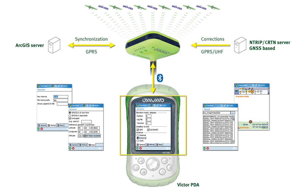 Javad GNSS introduces Javad ArcPad Extension. JAVAD ArcPad Extension controls the GNSS receiver to manage the surveying process. Synchronizes ArcPad with ESRI’s GIS server by utilizing integrated wireless communication technology.
NovAtel introduces the SMART-AG. Standard configuration supports GPS L1, GLONASS L1, and SBAS. Customer can add update rates to 20Hz.
Magellan Professional introduces the ProFlex 500. Standard configuration supports GPS L1, GPS L2, and SBAS. Customer can add GPS L2C, planned GPS L5, planned Galileo and updates rates to 20Hz.
Hemisphere GPS introduces the XF-101 for Juniper Systems Archer. Standard configuration supports GPS L1 and SBAS.

Pacific Crest introduces the Advanced Data Link (ADL) UHF radio. Standard configuration supports a 0.1 -4.0 Watt programmable transceiver, a 40 MHz frequency range and support for both 12.5 and 25 kHz channel bandwidth. It is compatible with existing products from Pacific Crest.
Topcon Positioning Systems introduces the Net-G3A. Standard configuration supports GPS L1, GPS L2C, GLONASS, planned GPS L5, planned Galileo, SBAS and updates rates to 100Hz.
Just a reminder that next week is the annual ION (Institute of Navigation) GNSS conference in Savannah, Georgia, as well as the annual CGSIC (Civil GPS Service Interface Committee) meetings. We’ll be blogging daily from CGSIC and ION. Keep your browser pointed at the GPS World website all week and hit the refresh button occasionally to see what’s going on at the conference.
Editor’s note: This article was orginally written in April 2006. Although the basic premise of the article stands, some of the information is dated. We plan on updating it in the next couple of months.
The world of satellite positioning is changing . . . a lot. Global Navigation Satellite System (GNSS) is slowly but most certainly replacing GPS as the acronym used when discussing satellite navigation. The annual ION (Institute of Navigation) GPS conference is now known as the ION GNSS conference. The International GPS Service is now called the International GNSS Service. For the time being, GPS is still the only game in town. However, a revamped Russian GLONASS (GLObal NAvigation Satellite System) program and the European Galileo program will change the landscape of satellite positioning forever. What’s more, GPS itself is undergoing significant enhancements over the coming decades that will improve the integrity and accuracy of the data it produces.
With respect to surveying and mapping, these new systems and enhancements raise many questions about accuracy, tracking performance, cost, upgrades, and other issues: “Should I wait for a full L2C constellation before upgrading my receivers? Should I wait for Galileo to be operational before making my next major GPS equipment purchase decision?”
Predicting the Future
First of all, Galileo, GPS L5 and GPS III (L1C) are still several years away from having constellations substantial enough to make a difference. A lot can happen with receiver technology before then, so placing any significant weight on the “L5/Galileo-ready” feature of a receiver today may not make much sense. In fact, they are sort of “vaporware” because no L5 signal exists yet to test with and the Galileo folks have been reluctant to even release the signal specification to developers.
Additionally, the competitive landscape could change dramatically. L2C opens the market for other companies to design dual-frequency receivers without having to develop the L2 semicodeless techniques used today (techniques that are technically challenging and filled with a minefield of patent blocks). Granted, it’s not just receiver hardware that makes a GPS survey solution, but L2C certainly eliminates
a major roadblock for companies interested in competing in the survey market space.
Whereas the survey-grade GPS equipment manufacturers have been quick to announce products that are L2C/Galileo/GLONASS-capable, it’s interesting to note that very few mapping-grade (meter-level differential GPS) and no consumer-grade (autonomous) equipment companies have given GNSS the same attention. Why? Because today’s GPS is good enough for consumers. They can live with intermittent GPS coverage and still navigate from Point A to Point B. Survey-grade GNSS doesn’t work that way. It’s a satellite-hungry technology.
For mapping-grade product lines, there is technical value in using the GPS, GLONASS and WAAS, such as being able to work more productively under trees and around buildings. As I wrote in the original 2006 article, mapping-grade receivers will eventually exploit GNSS and that has started. Manufacturers have introduced GPS+GLONASS mapping-grade receivers in the past year. But remember that there are limited sources of differential correction data for GLONASS data. WAAS doesn’t support it. OPUS doesn’t support it yet. NDGPS doesn’t support it. There are a few CORS stations that support GLONASS and the National Geodetic Survey (NGS) said it’s going to offer GLONASS orbits by the end of 2009. But, essentially, one would have to setup their own reference station in order to post-process GLONASS data, or use an RTK Network that is broadcasting GPS+GLONASS corrections.
The killer app for GNSS — and what has driven companies to buy GNSS equipment now — is centimeter-level, real-time positioning (or RTK, RealTime Kinematic, as it’s commonly referred to). GPS/GLONASS receivers have existed in the survey and precise-positioning market space for many years, and they have finally proven their value after years of GLONASS uncertainty. Using only GPS, RTK still has “brownout” times during the day, especially in tough GPS environments in which satellite visibility is limited. Simply put, there are not enough operational
GPS satellites to fully meet the demands of real-time, centimeter-level positioning in many cases.
A System Primer
The following will discuss the different GNSS implementation benefits and rough schedules.
GLONASS: The RTK Partner. GLONASS is Russia’s version of GPS. It may surprise you to know that the first GLONASS satellite was launched more than 25 years ago (1982), but due to political and economic issues in Russia, the system never reached maturity as a standalone system. In recent years, however, GLONASS has earned consumer confidence and has proven to be a useful augmentation to GPS for applications using RTK.
Outside of RTK applications, GLONASS hasn’t been shown to add value to GPS. Markets such as survey-grade postprocessing, mapping-grade GIS don’t have the cost–benefit payoff for GLONASS that RTK does. Therefore, very few GPS/GLONASS receivers are sold outside of the RTK market space.
For a long time, GLONASS was stagnant in terms of market acceptance. Without going into too much history, credit the increased popularity of GLONASS in RTK applications to the marketing of Javad Positioning Systems’ technology by Topcon Positioning Systems beginning early this decade. Javad and Topcon have since split (2004) but enough GPS/GLONASS systems had been fielded by then that the GPS/GLONASS RTK solution had proven to be effective and reliable. Today, nearly all major GPS manufacturers offer a GPS+GLONASS RTK system.
There are currently 17 operational GLONASS satellites and six more are scheduled for launch by the end of 2009. A full 24-satellite GLONASS constellation is scheduled to be in orbit by the end of 2010. The legacy and unreliable GLONASS satellites have been retired. The current GLONASS-M satellites have a design life of seven years. GLONASS-K satellites, with a design life of 10 years and sporting a new CDMA design for close compatibility with GPS, is due to launch at the end of 2010.
Since the 2006 article, Russia made an historic announcement that they will begin including CDMA signal structure on their next generation GLONASS-K satellites that are scheduled to begin launching at the end of 2010. This is a very significant development that will ease the complexity of designing GPS+GLONASS receivers. It will also result in newer
There is one serious technical consideration regarding GLONASS. Unlike GPS and Galileo, which use CDMA (Code Division Multiple Access) signal structure, GLONASS uses FDMA (Frequency Division Multiple Access) signal structure. With GPS and Galileo providing 57 satellites using CDMA, will the additional receiver complexity required to process GLONASS data motivate manufacturers to ignore GLONASS in the future? It’s a valid question.
Galileo Gets Started. Galileo is the European counterpart to GPS. Unlike GPS and GLONASS, which are financed and controlled by their countries’ respective military organizations, Galileo is controlled by civilians; the majority of the system development and all of the system maintenance are funded with commercial capital. It is a GNSS that has been targeted at commercial applications since its inception. It’s
designed to have a 30-satellite constellation (27 plus three spares), as well as a complement of groundstation equipment. The satellites orbit at slightly higher altitudes than GPS, but the operating principles are the same. The proposed constellation is designed so at least eight satellites are in view at all times.
The Institute of Navigation’s Global Navigation Satellite Systems (ION GNSS) conference is one of my two favorite industry events of the year; the other being the ESRI conference. At ESRI, I mix it up with GPS technology users, listen to what they are doing and what they want to do with the technology. At ION, I listen to GNSS designers and researchers.
ION GNSS is where these heady folks come together to share ideas and show the fruits of their labor. It’s also a place where GNSS policy-makers and administrators meet and share ideas. As with GNSS engineers, the administrators and policy-makers are an important part of the future of GPS technology. If a budget gets whacked on a certain GNSS program (say, for example, NDGPS), do you think companies will continue to spend R&D dollars on that technology? If you want to know the future of GNSS and how it will affect surveying, look at R&D today.
What’s so fun for me about ION GNSS is seeing where engineers spend their money and time. The research they present today will be in products you can use tomorrow.
But first, be sure to sign up for my free webinar to be held on September 15. I’ll be talking about modernized GPS signals (L2C, L5) and GLONASS. Do they (or in the case of L5, will it) really make a difference? Let’s talk. I’ll take your questions online after making a presentation.
I hope I’ve made this clear in the past and if not, here goes. I’m not a GNSS scientist. Not even close. Yes, I’ve managed product development where we integrated GPS technology and software to create surveying and mapping products. Yes, I managed the software and hardware engineers who made those products come to life. But if you asked me to write a line of C code or design a circuit, my 17 year old could finish it before I could start. I’m a block diagram sort of person that sees the big picture and communicates my vision reasonably well. And I listen to people, a lot.
Look at some of the ION GNSS presentation tracks below. Keep in mind that each one of these tracks has six to a dozen research papers within it — and these are only 11 of the more than 40 tracks at the conference. A full list of panel descriptions and speakers is available.
Just as a sampling, here are a few abbreviated abstracts from the above sessions:
Development and Field Testing of a DSP-Based Dual-Frequency Software GPS Receiver
B.W. O´Hanlon, Cornell University; T.E. Humphreys, University of Texas at Austin; M.L. Psiaki, P.M. Kintner, Jr., Cornell University
A real-time software GPS receiver for the L1 C/A and L2 C codes has been implemented on a Digital Signal Processor (DSP) and tested in a scintillation environment. This receiver is being developed as a low-cost space weather instrument with improved tracking robustness in comparison to a traditional semi-codeless dual-frequency receiver and with flexibility in its choices of signal tracking algorithms and data outputs. The receiver is capable of tracking 12 L1 C/A and 12 L2 C channels while also calculating receiver position and velocity and total electron content (TEC). The current work is a direct continuation of the work presented in Ref. 1. This work discusses several modifications to the software developed earlier, challenges addressed in updating the receiver to be easily adapted to new GNSS signals (e.g., L2C), and lessons learned from operation during ionospheric scintillation.Improving Real-Time Kinematic PPP with Instantaneous Cycle-Slip Correction
S. Banville, R.B. Langley, University of New Brunswick, Canada
Over the last decade, precise point positioning (PPP) proved to be a powerful processing strategy. It vastly spread in several fields of applications such as atmospheric sciences, geodynamics, surveying in remote regions, processing of large networks, etc. On the other hand, the success of this technique in kinematic mode (with a moving receiver) is still muted due to a rather long convergence period required to obtain a centimetre level of precision. Several efforts were mounted to overcome this limitation, which led to the possibility of fixing carrier phase ambiguities to integers, which is the key to reducing the convergence period. In our approach, both carrier-phase and pseudorange measurements are included in the processing which allows estimating, not only receiver position change and receiver clock offset variation, but also cycle-slip parameters. Since time-differencing over short time spans is used, the assumption that instrumental biases cancel out seems reasonable. Hence, the cycle-slip parameters estimated are integers and conventional ambiguity search methods can be used to statistically determine the optimal cycle-slip (ambiguity) combination. Once the correct combination of integer cycle slips has been determined, their effects can be removed from the carrier-phase measurements, and the PPP processing can be executed without having to introduce new ambiguity parameters in the estimation filter. The benefit of this additional step is that a continuous time series can be obtained for the receiver coordinates, without the need for a new undesirable convergence period.Augmenting Low-cost GPS/INS with Ultra-wideband Transceivers for Multi-platform Relative Navigation
A. Vydhyanathan, H. Luinge, M. Tanigawa, F. Dijkstra, Xsens Technologies B.V., The Netherlands; M.S. Braasch, M. Uijt de Haag, Ohio University, USA
This paper explores the use of impulse radio based Ultra-wideband transceivers to augment the low-cost GPS/INS navigation estimates in GPS-challenged/denied environments for multi-platform relative navigation. Such low-cost GPS/INS systems are increasingly being used in automobile, aerospace and marine applications for vehicle dynamics analysis, performance testing, Unmanned Aerial Vehicles (UAV) and Unmanned Ground Vehicles (UGV), autonomous attitude and navigation control and camera/LADAR stabilization and correction. The architecture and algorithm developed in this paper has independent ´loosely-coupled´ GPS/INS EKF´s running on each platform. A separate filter then takes the independent filter outputs and combines them with the ranges derived from the Ultra-wideband broadcasts to output relative navigation estimates.The Benefits of Multi-constellation GNSS: Reaching up Even to Single Constellation GNSS users
B. Bonet, I. Alcantarilla, GMV, Spain; D. Flament, C. Rodriguez, EGNOS Project Office, ESA, France; N. Zarraoa, GMV, Spain
Europe has launched, under the European Space Agency’s (ESA’s) European GNSS Evolution Programme, the MRS initiative. MRS standing for Multi-constellation/multi-frequency Regional System, the initiative is putting different teams of experts into the exciting goal of defining the paths for the most successful GNSS usage on a future of multiple choices. ESA has prepared a detailed experimentation plan aimed to proof the benefits that the multi-constellation approach can provide to today´s GNSS users. This plan covers a wide range of objectives covering different user domains (aeronautical, land mobile, maritime) eq
uipped with different types of receivers. This set of experimentations will rely on the deployment of several Test Beds combining multi constellation multi-frequency processing and several broadcast channels (GEO, MEO, terrestrial). Among the first experimentations planned, there are some devoted to experiment and validate the performance benefits for SBAS users (GPS L1 only first then GPS/GLONASS or GPS/Galileo — dual-frequency SBAS users). This paper presents the outcome of the first step of this experimentation campaign, which has been performed based on the magicSBAS tool, a flexible SBAS processing platform, able to acquire single and dual frequency GLONASS data, in addition to GPS, to compute and provide both standards SBAS corrections and integrity, as well as augmentation to GLONASS.
From studying the track titles and abstracts, one can read between the lines and take a peek into the future of GNSS products. It’s clear to see that software receivers, SBAS, other GNSS, other sensor technology, PPP, atmospheric modeling and mitigation, and more reliable positioning all are active R&D topics that will mold the products in our future…some now and some a few years out.
I really enjoy this “look into the future” and will do my best to communicate the highlights to you. Our GPS World team will be at the ION GNSS conference in full force. Daily blogs will be written by several editors including myself. The GPS World website will be updated daily so be sure to check in throughout the week (September 21-25.)
The ION GNSS conference doesn’t actually start until Wednesday (kick-off is the plenary Tuesday evening) of that week. The Civil GPS Service Interface Committee (CGSIC) schedules their annual meeting on the two days prior to the ION GNSS conference. If you aren’t familiar with the CGSIC, I wrote an article about it a couple of years ago. Briefly, CGSIC is the body through which the civil GPS community can communicate with GPS authorities.
The two days of CGSIC meetings are chocked full of fantastic presentations from the status of GPS/GLONASS/Galileo/SBAS/NDGPS programs to presentation by users of GNSS. Normally I see the agenda posted on the CGSIC website, but I haven’t seen it there ye but check back in a day or two and I bet it will. Typically, the first day are program status briefings (GPS, GLONASS, QZSS, Galileo, SBAS, NDGPS, etc.). The second day contains breakouts sessions from the different subcommittees (US States and Localities, Survey Mapping & Geosciences, International and Timing). I’ll be giving a briefing on RTK Networks Tuesday at the US States and Localities subcommittee breakout session.
The guy who kicks my butt all over the landscape when I don’t file this column on time, GPS World editor Alan Cameron, also presents at CGSIC on Monday afternoon, with the topic “User Concerns.” For a preview of his presentation, see the latest installment in his Wide Awake blog, Wide Awake on the Midnight Train to Georgia [[http://stage.globalpositioningnews.com/gnss-system/wide-awake/wide-awake-midnight-train-georgia-8807]], in which he plays back results from a magazine survey of readers who answered the question, “Where is society going with GPS/GNSS use, and how will that change the GPS/GNSS industry?”
We’ll be blogging on the CGSIC meetings as well. Cameron and I will both have digital video recorders in our traveling bags, and we’ll post footage of highlights during the week. That’s another great way for you to get a bit closer to this goldmine of a conference.
In other notes, only 10 days after it was launched, the latest and last Block IIR-M GPS satellite was declared healthy and ready for service on August 28. Your receiver should be already tracking it and using it. It is identified as PRN05.
Meanwhile, the status of PRN01 (SVN49) that was launched back in March is still unhealthy and not usable. There’s been no significant news since the flurry of reports detailing its flaw a month ago. I suspect the Air Force will make some sort of announcement at the ION GNSS conference later this month with an update and/or plan to deal with the sick bird.
And again lastly, be sure to sign up for my free webinar to be held on September 15. I’ll be talking about modernized GPS signals (L2C, L5) and GLONASS. Do they (or in the case of L5, will it) really make a difference? Let’s talk about it. Sign up here.
By Matthias Söllner, Christian Kurzhals, Wolfgang Kogler, Stefan Erker, Steffen Thölert , Michael Meurer, Maktar Malik, and Manuela Rapisarda
GIOVE-B has been in orbit for just over one year. How well is it performing? In particular, what can we say about one of GIOVE-B’s pioneering features: its E1 CBOC signal? In this month’s column, we take a detailed look at a particular monitoring and assessment program set up to examine the GIOVE-B signals and discuss some of its initial CBOC results. The successful operation of this program bodes well for its use in future validation campaigns.

THE SECOND GALILEO TEST SATELLITE, GIOVE-B, was launched on April 27, 2008, and began transmitting navigation signals a few days later. It joined its older sibling, GIOVE-A, which was placed in orbit over two years earlier. Standing for Galileo In-Orbit Validation Element, the GIOVE satellites constitute the first in-orbit test phase in the development of the Galileo navigation system.
In addition to securing the frequencies for the system, the satellites are being used to assess key technologies for the full Galileo constellation. The GIOVE test phase will be followed by the In-Orbit Validation (IOV) phase during which four IOV satellites will be launched, two at a time, aboard Soyuz rockets from Europe’s spaceport in French Guiana. Together with a preliminary ground network, the IOV satellites will be used to validate the Galileo system as a whole, using advanced system simulators. The launches are expected to occur by the end of 2010.
But before the IOV phase can begin, a thorough analysis of the performance of the GIOVE satellites must be carried out to minimize any difficulties with the IOV satellites. This includes monitoring and assessing the different signals broadcast by the satellites.
The GIOVE satellites can transmit on all three Galileo frequencies, E5, E6, and E1 (also known as L1) but only on two simultaneously (either E1-E5 or E1-E6). A variety of modulation types can be transmitted on the different frequencies by both satellites to test their use for the different Galileo services to be implemented for the operational constellation. These include alternative binary offset carrier (BOC) and quadrature phase shift keying on E5 and cosine BOC (BOCc) and binary phase shift keying on E6. On E1, the satellites have different capabilities. Although both satellites can transmit BOCc on this frequency, GIOVE-A can additionally transmit a single BOC signal with a subcarrier frequency of 1.023 MHz and a spreading code chipping rate of 1.023 MHz (BOC(1,1) ) whereas GIOVE-B transmits a more versatile multiplexed composite BOC or CBOC, which linearly combines BOC(1,1) and BOC(6,1). The CBOC signal is being transmitted by GIOVE-B to explore its performance, usability, and any possible side effects including its use in receivers designed to track a BOC(1,1) signal.
GIOVE-B has now been in orbit for just over one year. How well is it performing? In particular, what can we say about one of GIOVE-B’s pioneering features: its E1 CBOC signal? In this month’s column, we take a detailed look at a particular monitoring and assessment program set up to examine the GIOVE-B signals and discuss some of its initial CBOC results. The successful operation of this program bodes well for its use in future validation campaigns.
The first measurements of the navigation signals transmitted by the second Galileo test satellite, GIOVE-B, were recorded during the night of May 7, 2008, following the successful launch from Baikonur a little over a week earlier on April 28. During the In-Orbit Test (IOT) phase of the mission, which lasted about three months, a program of intensive measurements was carried out by the German Aerospace Center (Deutsches Zentrum für Luft- und Raumfahrt or DLR) and the Astrium subsidiary of the European Aeronautic Defence and Space Company (EADS) using the 30-meter high-gain antenna at Weilheim/Lichtenau, near Munich, Germany. These and follow-on activities were performed under a bilateral agreement between the European Space Agency (ESA) and DLR’s Institute of Communication and Navigation on the exploitation of the GIOVE satellites.
The first measurements indicated that the navigation payload suffered no damage or degradation with regard to power and signal-in-space (SIS) quality during the launch of the satellite. After the successful completion of the IOT phase, the satellite configuration was maintained for long intervals to allow stability and long-term quality assessments within the ESA GIOVE mission activities and to stabilize ground segment operation. DLR and Astrium continued their measurements and analysis on GIOVE-B signals, focusing on modulated power and on modulation and correlation quality. The observation intervals included an eclipse season, when GIOVE-B spends a fraction of its orbit in the Earth’s shadow. Any impact of the corresponding temperature variations on signal transmission characteristics and key navigation parameters was of special interest.
This article focuses on modulated spectral power analysis of GIOVE-B signals for the detection of frequency and elevation-angle-dependent variations in the transmitted signal spectrum and power. Also, a detailed in-phase/quadrature-phase (I/Q) sample analysis is presented, focusing on modulation correctness and correlation distortions. These assessments are based on sample files of a few seconds of navigation signals as received by a calibrated high-gain antenna and recorded with the BayNavTech Signal Experimentation Facility (BaySEF). We have evaluated, in particular, correlation loss and S-curve bias since these parameters are very sensitive to onboard signal distortions although their reliable evaluation is quite challenging. In this article, we concentrate on the analyses of the E1 composite binary offset carrier (CBOC) modulation.
We discuss the GIOVE-B measurement and evaluation parameter results from the initial IOT phase and from later phases, including those from an eclipse period. This comparison of measurement results — spread over the first year of operations — demonstrates the excellent stability of signal power, modulation, and correlation quality of the GIOVE-B signals.
GIOVE-B E1 Signal
GIOVE-B can transmit navigation signals either simultaneously in the Galileo E5 and E1 bands or in the E6 and E1 bands. At E1, with a center frequency of 1575.42 MHz, GIOVE-B transmits three signal components called E1-A, E1-B, and E1-C. The E1-A signal has a BOCcos(15,2.5) modulation, with 2.5575 MHz code chip-rate and a binary cosine-type subcarrier modulation of 15.345 MHz. The B- and C-components have CBOC(1,6,1,10/1) modulation. Within this type of multiplexed BOC implementation, the code chips are provided at a constant rate of 1.023 MHz, modulated with a composite quaternary subcarrier with rates of 1.023 and 6.138 MHz. The latter part, called the BOC(6,1) subcarrier, has a relative power of 1/11 and is added to the BOC(1,1) binary subcarrier in CBOC-B and subtracted for CBOC-C. From the beginning of May 2008 until July 2009, GIOVE-B transmitted signals 96.8% of the time. Considering the experimental nature of the satellite, this represents a very successful operation.
Signal Quality and Relevance
In GNSS operations, signal quality assessment generally refers to the behavior of the navigation signals as transmitted from individual satellites. In this article, we assess two major aspects: the transmitted signal power and the frequency-transfer distortions of the satellite relative to the ideal signal definitions.
Why should we consider these aspects in particular? For transmitted signal power, the answer is obvious. In addition to proof of compliance with regulatory declarations, verification and monitoring of signal power is relevant for the system provider to commit to certain navigation service performance.
Concerning frequency-transfer distortions, the answer may be less obvious. The relevance is obtained via the impact of distortions on a receiver’s correlation function. First, the available maximum correlation power for a receiver binary replica may be affected. This is due to changes in the power sharing of the signal components within the complete signal and due to reduced matching of distorted transmitted signals with the ideal receiver replica. Second, the shape of the correlation function may suffer from asymmetric distortions, leading to receiver-dependent biases in the discriminator lock point. The most relevant receiver parameters are the input bandwidth and the discriminator type, especially the discriminator spacing (early-late spacing). With respect to this, user receivers and receivers in the control system ground segment (used to derive the satellite orbit and clock parameters) may differ. This leads not only to timing but also to positioning errors, if the distortions are different for different satellites.
These are the main reasons why we need to analyze and control the corresponding distortions for the Galileo system.
For an accurate assessment of transmitted signal power and frequency distortions, we had to obtain measurements with a highly directive antenna. This is essential in order to lift the instantaneous signal far above the noise floor and to avoid environmental distortions from interference as well as multipath.
But why don’t we consider also other aspects of signal quality such as the correctness of the navigation message or the stability of hardware delays and clocks? Because measurements with the highly directive antenna are not so appropriate for an assessment of these parameters. Instead, continuous monitoring over weeks or longer is preferred, based on measurements from a network of distributed navigation receivers. Such monitoring likely will be discussed in other publications.

Evaluation Parameters
For the assessment of the satellite’s radiated power in the individual navigation bands, absolute calibrated spectral measurements are evaluated for spectral flux densities integrated over frequency. These parameters provide a first insight into spectral asymmetries and variations over time.
Other parameters are used to evaluate the distortions in the instantaneous transfer characteristics of the satellite. They are derived from wide-band recorded baseband-signal samples of up to a few seconds duration.
Initially, we consider the I/Q probability density of the signal after Doppler frequency shift removal, well known from communication system analysis as scatter plots. Secondly, as introduced in the previous section, we want to quantify the impact of transfer distortions on the navigation performance obtained for ideal navigation receivers. The corresponding acquisition and tracking performance is based on the correlation function.
We define the normalized correlation function with respect to ideal receiver properties in order to separate the satellite transmit distortions of interest from receiver distortions according to the following equation:

with
From this normalized correlation function, we can derive the primary relevant navigation parameters, which are, as previously mentioned:

Correlation Loss. For a given (distorted) signal, the correlation loss (CL) quantifies the loss in correlator output power relative to an ideal signal. This can be formulated by
![]()
where
![]()
It should be noted that the ideal baseband signal here is the multiplexed signal including all signal components, also band limited with a brick-wall filter to the bandwidth of interest.
S-Curve Bias. The navigation receiver obtains the (noiseless) code delay by following the zero crossing of the code discriminator. The output as a function of delay resembles the letter “S” or its reflection and is called the S-curve. For asymmetric distortions in the correlation function, it turns out that different code-tracking loops may have different lock points, as illustrated in FIGURE 1 for an arbitrary example.
To quantify this effect with a reasonable compromise between parameter complexity and practical value, a non-coherent (early minus late) power discriminator is considered over a wide range of early-late spacings, . This refers to the code discriminator of
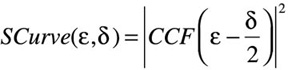
with its lock point, ![]() , defined by
, defined by
![]() .
.
Then, the spreading of the lock point is the S-curve bias, SCB, given by
![]() ,
,
considering all δ in the range [0, δmax], with
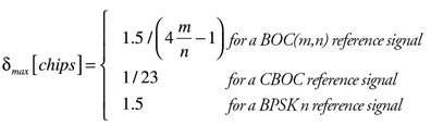
Those interested in additional candidate signal-quality parameters, more detailed descriptions, or a theoretical analysis of the impact of satellite distortions on navigation performance parameters should consult the paper “GNSS Offline Signal Quality Assessment” listed in Further Reading.

Weilheim Measurement Setup
As previously mentioned, for accurate measurements of the various signal-quality parameters, the signal needs to be lifted above the noise and multipath, and any interference needs to be suppressed considerably. Moreover, as the signal quality from the satellite needs to be assessed separately, any measurement-system transfer distortions need to be calibrated out as much as possible.
That’s why DLR installed a measurement and calibration system at their 30-meter high-gain dish antenna at Weilheim for GIOVE signal performance measurements. This measurement setup was completed for high capacity signal recording with one rack of the BaySEF equipment in cooperation with EADS Astrium.
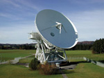
The 30-meter antenna, as shown in the opening graphic, is the main core of this verification facility. This antenna is based on a shaped Cassegrain system with elevation over azimuth mount, with higher than 50-dB gain and a beam width around 0.5° at L-band. The absolute position accuracy of this antenna is 0.001° in each direction. The signals are directed from the parabolic main reflector to the measurement cabin via a hyperbolic sub-reflector, a waveguide, and a second flat sub-reflector. One big benefit of this construction is the direct access to the installed feed in the cabin and the possibility to place the complete measurement equipment next to the feed, avoiding long connection cables.
The signals are recorded with BaySEF and for individual frequency bands (selected by switchable band pass filters) and also with a vector signal analyzer (VSA) of at least 80 MHz bandwidth. Moreover, a signal with up to 300 MHz bandwidth can be recorded with a digital oscilloscope, if the VSA is used for down conversion. Interfaces to other measurement equipment, such as navigation receivers, have already been prepared for future extension. The whole setup is referenced to a highly stable cesium frequency standard. We essentially use the BaySEF equipment as a high-capacity multiband bit grabber in this setup.

The main BaySEF applications are the verification and monitoring of GNSS SIS and support for the design of applications based on parametric software-receiver evaluations. The key features most relevant for the signal-quality assessment discussion of this article are:


Measurement Calibration
Accurate system calibration is the key to reliable signal quality measurements. To achieve a combined absolute measurement uncertainty significantly less than 1.0 dB (required for EIRP assessments), it is essential to calibrate precisely every used part of the system. In addition to all RF components of the receiving system, this also includes the high-gain antenna itself.
For the characterization of the high-gain antenna, two values are assessed: antenna pointing accuracy and gain. A pointing offset of about 0.04° was measured exactly with a known L-band pilot signal from the Artemis satellite and corrected in the antenna control. For gain characterization over the complete L-band frequency range of interest, the radio “star” Cassiopeia A is used. Cas A (actually a supernova remnant) is one of the strongest wide-band radio emitters in the northern hemisphere. With the help of the well-known flux density of Cas A, the gain-to-noise-temperature ratio (G/T) can be measured. After precise determination of the system noise temperature, T, the antenna gain, G, itself can be found.
For online calibration of absolute gain drifts in the measurement system, a frequency-and-power-stabilized signal generator is used in combination with two power meters.
The relative frequency transfer distortions of the receiving system are calibrated with two techniques. A network analyzer periodically provides precise measurements of gain and phase of the RF path from the antenna feed to the measurement devices.
To include also down-converting measurement devices such as the BaySEF, the injection of wide-band calibration signals is used, and simultaneously measured with a commercial digitizer (VSA).
The desired in-band measurement system transfer characteristic (relative to the VSA-characteristic, which is assumed to be ideal) is then extracted by means of de-convolving the calibration signal sampled by the device to be calibrated with the VSA-sampled reference signal.
Corresponding transfer characteristics obtained for the RF path (from network analysis) and for the BaySEF (from wide-band calibration signals) were combined to derive the equalization filter applied in post-processing the recorded samples.
Power Measurement Results
For analysis of the transmitted signal power of the GIOVE-B E1 CBOC and its variation, we have recorded a large number of spectral measurements over single satellite passes. A typical example of a single power spectral density measurement — here normalized to unit power — is shown in FIGURE 2, overlaid on the ideal spectral envelope. After absolute power calibration, we integrate the spectral power flux density over a reference bandwidth of 40.92 MHz and over the individual main lobes of the BOC(1,1) and BOCc(15,2.5) components, as illustrated in Figure 2. This procedure is used to detect the variation of transmitted signal power and possible signal asymmetries over time.
Parameter results are shown first for an early satellite pass during the IOT campaign on May 11, 2008 in FIGURE 3. Main variations in this figure are as typically expected from the cut of the measurement pass through the satellite antenna pattern. Also, the overall main-lobe power of the BOC(1,1) and the BOCc(15,2.5) components are similar, but with a strong asymmetry between upper and lower main-lobe power of the BOCc(15,2.5) component.
A closer look at the time-dependency of this asymmetry is given in FIGURE 4, showing a stable low power difference of about 0.2 dB between the BOC(1,1) main lobes and a mean power difference of 0.8 dB between the BOCc(15,2.5) main lobe with ±0.2 dB variations over time.
The second record was captured more than a year later, with similar results as shown in FIGURE 5, which indicate a stable transmission power. Only the mean main-lobe asymmetry of the BOCc(15,2.5) signal, as shown in FIGURE 6, is slightly smaller and with a different shape in its time-dependency. The measurement passes surely provided different cuts through the satellite antenna pattern. Therefore, we assume that these variations mainly indicate some antenna-pattern frequency dependency, as will be emphasized also in the following signal quality measurement results. For precise characterization, measurements and evaluations for many more satellite passes would be required.


Signal Quality Results
In this section, we will show some GIOVE-B E1 signal quality results as obtained from BaySEF measurement data collected at Weilheim. The results presented are from two passes with the satellite in E1 CBOC-transmission mode:
The modulation type of the E1 signal can be seen from the scatter plot, shown in Figure 7, which is derived from about 50 millisecond-signal-samples after Doppler removal. The overlay, with the eight phase points of the ideal constant envelope signal, allows clear identification of the interplexed CBOC signal. Due to bandwidth limitation, distortions, and noise jitter, the individual phase states have been enlarged, and transition traces become visible. Also, the symmetry of phase states becomes slightly deformed. How much this affects measurable navigation performance is not directly obvious from such a plot.
A better indicator of navigation performance is the E1 interplex CBOC correlation function shapes as shown in FIGURE 8 (CBOC-B and -C) and FIGURE 9 (BOCc(15,2.5)), respectively. As for all the following evaluations, the E1 signals were brick-wall band-limited to 40.92 MHz (40 × 1.023 MHz), which was the performance bandwidth of interest, and up-sampled to a rate of 575 MHz. The differences in shapes are not due to distortions but due to different signs of the BOC(6,1) subcarrier in the B and C channels. Note the imaginary part due to signal distortions has been amplified 10 times to stress its presence.
For the shape of the BOCc(15,2.5) correlation function, a small asymmetry in the real part is visible when compared to the ideal band-limited autocorrelation function. This signal distortion effect might be relevant, leading to a higher chance for false lock in acquisition and tracking. However, current receivers have no problems in tracking these signals.
A direct visual assessment of these shapes does not allow us to draw many conclusions. More quantitative evaluations provide the performance parameters of correlation-loss and lock-point-bias behavior.
Example results of the correlation-power evaluation for the GIOVE-B CBOC-B signal component are shown in FIGURE 10, with the red curve showing the correlation power of succeeding code periods relative to the total signal (which also includes the CBOC-C and BOCc(15,2.5) signal components). A curve of similar shape, shown in blue, is obtained for the ideal reconstructed signal using the specified codes and actual data bits of all components synchronized to the input signal. Obviously, the strong jitter of more than 0.1 dB is due to code cross-correlations. The correlation loss is obtained by taking the difference (see Figure 10b), which has a much lower variation with a maximum value of about 0.02 dB. This variation is still dominated by residual distortion differences of the code-cross-correlation values of the GIOVE-B codes as can be seen when accounting for the fact that equally colored dots in the figure correspond to equal code cross-correlations. Despite the variation, the negative loss is remarkable. This corresponds to a gain in usable signal power relative to the ideal case and is due to a stronger bandwidth limitation. This analysis indicates that the signal power of the wide-band signal component, BOCc(15,2.5), is more strongly reduced than for the narrow-band CBOC component, providing effectively a gain in relative correlation power for CBOC.
Next, we consider the lock-point bias of a noncoherent power discriminator as a function of early-late spacing (over the relevant range) for the CBOC-C signal component in FIGURE 11, evaluated for about 60 succeeding code periods. Again, different colors indicate different code-cross-correlation values. The corresponding S-curve bias is obtained by evaluating the peak-to-peak variation of this lock-point bias and is shown in FIGURE 12. Over this short period of 0.5 seconds, a quite stable value of about 1325 picoseconds is obtained with only 25 picosecond standard deviation mainly due to residual code-cross-correlation effects and residual noise.

It should be noted that all evaluation results include not only the satellite distortions but, in general, measurement distortion contributions. In fact, accurate measurement system calibration is one of the most critical issues for exact signal quality assessment of satellite transfer characteristics.
Mutual evidence of successful calibration is gained from the fact that similar results for correlation loss and S-curve bias of the CBOC-signal components have been obtained from measurements carried out by ESA together with Surrey Satellite Technology and the Science and Technology Facilities Council at the Chilbolton Observatory near Andover, England. However, even for the same measurement periods and perfect calibration, identical results may not be expected, as will be discussed here.

In addition to the signal-quality assessment of individual snapshot measurements, variation over observation direction and over time is of major relevance. Therefore, these evaluations have been performed for many snapshots of two single passes almost five months apart. The passes and measurement points mapped to the directions as seen from a satellite-antenna-fixed coordinate system are shown in Figure 13.
In FIGURE 14, the results of correlation loss and S-curve bias are shown for both passes mapped to the satellite antenna off-axis angle. For a monotonic x-axis, a sign was added to this angle here, with negative values for the ascending part of the pass and positive values for the descending part as seen from Weilheim.


The correlation-loss results for both passes vary about ±0.1 dB around 0.7 dB for BOCc(15,2.5), around -0.5 dB for CBOC-C and around -0.55 dB for CBOC-B. Also, the measured S-curve-bias results are in the same range for both passes, which is about ±100-200 picoseconds around 1200 picoseconds for CBOC-B and CBOC-C and ±2 picoseconds around 23 picoseconds for BOCc(15,2.5). Furthermore, these plots show smooth variations over the antenna off-axis angle, obviously also with some azimuth dependency due to the different shapes for each pass. It is remarkable that the relative shapes of the correlation-loss and S-curve-bias plots are so similar.
Even if measurement system instability may be a contributing factor, most of the variations are thought to be due to the directional dependency of the satellite antenna pattern. See also the similarity of results from both passes at the one end of the high off-axis angles, corresponding to similar azimuth angles. These results indicate that for full characterization of signal quality over the satellite antenna pattern, further well-calibrated measurements over several passes would be required.
During the measurement pass of September 29, 2008, a few measurement points were taken when the satellite was in eclipse. Corresponding results marked by black points in the figures show almost no impact of the eclipse on correlation loss and S-curve bias. Further measurements and evaluations would be required to confirm finally that the larger changes afterwards are not due to the eclipse.
Conclusions
This article described some of the GIOVE-B navigation SIS performance characterizations carried out by DLR and EADS Astrium in collaboration with ESA during the past year. These characterizations were achieved using a very accurate measurement system, calibrated in absolute power, relative amplitude, and phase over several frequency bands. For this purpose, several calibration approaches have been adopted and are still being optimized.
The similarity of results from measurements spaced several months apart indicates excellent long-term stability of the considered characteristics. Also, it has been demonstrated that a satellite-eclipse period seems not to affect modulation and correlation quality in a relevant manner.
As expected and already known from previous work, the satellite provides some frequency-dependent directional variations in its transmitted signal power characteristics, which also affects signal quality.
During the described campaign, the observed variations can be considered as moderate. A continuation of the monitoring activity is under consideration, to further improve the coverage of the characterizations.
During these GIOVE-B measurements and evaluations, all involved teams gained considerable experience in accurate characterization of the navigation signals transmitted from the satellite, and the operation of instruments and signal evaluation was thoroughly verified and cross-validated. The knowledge and experience gained will be very useful for future navigation satellite validation campaigns.
Acknowledgments
We would like to thank DLR’s German Space Operations Center for use of the Weilheim antenna and the colleagues who operate and maintain it. BaySEF is part of the BayNavTech program, which is supported by the Bavarian Government (Ministry for Economic Affairs, Infrastructure, Transport and Technology). The activity reported in this article was performed under a bilateral agreement between ESA and DLR’s Institute of Communication and Navigation on the exploitation of GIOVE satellites and the GIOVE signal-quality-characterization effort has been supported by ESA. This article is based on the paper “One Year in Orbit – GIOVE-B Signal Quality Assessment from Launch to Now” presented at the European Navigation Conference GNSS 2009, held in Naples, Italy, May 3–6, 2009.
Manufacturers
Measurement equipment included a Rohde & Schwarz GmbH & Co. KG (www.rohde-schwarz.com) FSQ26 vector signal analyzer. The EADS Astrium facility did not use commercial receivers to capture the GIOVE-B signals discussed in this article.
MATTHIAS SÖLLNER is senior expert on navigation signal engineering. CHRISTIAN KURZHALS and WOLFGANG KOGLER are navigation signal engineers focusing on payload aspects and performance verification, respectively. All are working at the Astrium GmbH subsidiary of the European Aeronautic Defence and Space Company N.V. (EADS).
STEFAN ERKER and STEFFEN THÖLERT work on GNSS validation and signal analysis at the German Aerospace Centre in Oberpfaffenhof-en with MICHAEL MEURER, who is responsible for performance issues concerning the Galileo system.
MAKTAR MALIK is the payload system manager for GIOVE-B at the European Space Research and Technology Centre in Noordwijk, The Netherlands, where he works with MANUELA RAPISARDA, who is a radio navigation engineer providing system support to the Galileo Project Office.
Further Reading: Click here for references related to this article.
By Marcel Baracchi-Frei,
Grégoire Waelchli, Cyril Botteron,
and Pierre-André Farine
The idea of a software receiver is to replace the data processing implemented in hardware with software and to sample the analog input signal as close as possible to the antenna. Thus, the hardware is reduced to the minimum — antenna and analog-to-digital converters (ADCs) — while all the signal processing is done in software. As current mobile devices (such as personal digital assistants and smartphones) include more and more computing power and system features, it becomes possible to integrate a complete GNSS receiver with very few external components.
One advantage of a software receiver clearly lies in the low-cost opportunity, as the system resources such as the calculation power and system memory can be shared. Another advantage resides in the flexibility for adapting to new signals and frequencies. Indeed, an update can easily be performed by changing some parameters and algorithms in software, while it would require a new redevelopment for a standard hardware receiver.
Updating capabilities may become even more important in the future, as the world of satellite navigation is in complete effervescence: Europe is developing its own solution, Galileo, foreseen to be operational in 2013; China has undertaken a fundamental redevelopment of its current Compass navigation system; Russia is investing huge sums of money in GLONASS to bring it back to full operation; and the U.S. GPS system will see some fundamental improvements during the next few years, with new frequencies and new modulation techniques. At the same time, augmentation systems (either space-based or land-based) will develop all over the world.
These future developments will increase the number of accessible satellites available to every user — with the advantage of better coverage and higher accuracy. However, to take full advantage of the new satellite constellations and signals, new GNSS receivers and algorithms must be developed.
The definition of a software receiver (SR) always brings some confusion among researchers and engineers in the field of communications and GNSS. For example, a receiver containing multiple hardware parts which can be reconfigured by setting a software flag or hardware pins of a chipset are regarded by some communication engineers to be a SR. In this article, however, we will consider the widely accepted SR definition in the field of GNSS; that is, a receiver in which all the baseband signal processing is performed in software by a programmable microprocessor.
Nowadays, software receivers can be grouped in three main categories:
A modern GNSS receiver normally contains a RF front-end, a signal acquisition, a tracking, and a navigation block. A hardware-based receiver accomplishes the residual carrier removal, PRN code-despreading, and integration at the system sampling rate. Until the late 1990s, due to the limited processing power of microprocessors, these signal functions could only be practically implemented in hardware.
The GNSS SR boom really started with the development of real-time processing capability. This was first accomplished on a digital signal processor (DSP) and later on a commercial conventional personal computer (PC). Today, DSPs are increasingly replaced by specialized processors for embedded applications.
Data rate. The ideal software receiver would place the ADC as close as possible to the antenna to reduce hardware parts to a minimum. In that sense, the most straightforward approach consists of digitizing the data directly at the antenna, without pre-filtering or pre-processing. But as the Nyquist theorem must be fulfilled (that is, sampling with at least twice the highest signal frequency), this translates into a data rate that is, for the time being, too high to be processed by a microcontroller.
Considering the GPS L1 signal and assuming 1 quantization bit per sample, this leads to the following values:
FGPSL1 5 1.57542 GHz
FSampling > 2 3 FGPSL1 5 3.15 GHz
Data rate > 3.15 GBit/s 5 393 MB/s
In order to reduce the data throughput, a solution such as a low intermediate frequency (IF) or a sub-sampling analog front-end must be chosen. In a low IF front-end, the incoming signal is down-converted to a lower intermediate frequency of several megahertz. This allows working with a sampling (and data) rate that can be more easily handled by a microcontroller. With the new BOC signal modulations (used for the Galileo E1 and the modernized GPS L1 signals) that have no energy at and near DC, a zero-IF or homodyne architecture is also possible without SNR degredation due to DC offset, flicker noise, or even-order distortions.
The sub-sampling technique exploits the fact that the effective signal bandwidth in a GNSS signal is much lower than the carrier frequency. Therefore, not the carrier frequency but the signal bandwidth must be respected by the Nyquist theorem (assuming appropriate band-pass filtering). In this case, the modulated signal is under-sampled to achieve frequency translation via intentional aliasing. Again, if the GPS L1 signal is taken as an example with assuming 1 quantization bit per sample, this leads to the following values:
Bandwidth GPS L1 5 2 MHz
FSampling > 2 3 Bandwidth 5 4 MHz
Data rate > 4 MBit/s 5 500 kB/s
However, as the sub-sampling approach is still difficult to implement due to current hardware and resources limitations, a more classical solution based on an analog IF down-conversion is often chosen. That means that the signal is first down-converted to an intermediate frequency and afterwards digitized.
Baseband Processing. Considering an IF-based architecture, the ADC provides a data stream (real or complex), which is first shifted into baseband by at least one complex mixer. The signal is then multiplied with several code replicas (generally early, prompt, and late) and finally accumulated. Figure 1 shows an example of a real data IF architecture.

In hardware receivers, the local code and carrier are generally generated in real-time by means of a numerically controlled oscillator (NCO) that performs the role of a digital waveform generator by incrementing an accumulator by a per-sample phase increment. The resulting value is then converted to the corresponding amplitude value to recreate the waveform at any desired phase offset. The frequency resolution is typically in the range of a few millihertz with a 32-bit accumulator, and a sampling frequency in the range of a few megahertz.
Assuming that a look-up table (LUT) address can be obtained with two logical operations (one shift and one mask), and the corresponding LUT value reads with 1 memory access — which is quite optimistic — the amount of operations needed to generate the complex waveforms per channel is given in Table 1.

The real-time carrier generation is computationally expensive and is consequently not suitable for a one-to-one software implementation. Earlier studies [Heckler, 2004] demonstrated that, assuming that an integer operation and a multiplication take one and 14 CPU cycles, respectively (for an Intel Pentium 4 processor), the baseband operations (without carrier and code generation or navigation solution) would require at least a 3 GHz Intel Pentium 4 processor with 100 percent CPU load. Therefore, under these conditions, real-time operations are not suitable for embedded processors. Therefore standard hardware receiver architectures cannot be translated directly into software, and consequently new strategies must be developed to lower the processing load.
A major problem with the software architecture is the important computing resources required for baseband processing, especially for the accumulation process. As a straightforward transposition of traditional hardware-based architectures into software would lead to an amount of operations which is not suitable for today’s fastest computers, two main alternate strategies have been proposed in the literature: the first relies on single-instruction multiple-data (SIMD) operations, which provide the capability of processing vectors of data. Since they operate on multiple integer values at the same time, SIMD can produce significant gains in execution speed for repetitive tasks such as baseband processing. However, SIMD operations are tied to specific processors and therefore severely limit the portability of the code.
The second alternative consists in the bitwise parallel operations (sometimes also referred to as vector processing in the literature), which exploit the native bitwise representation of the signal. The data bits are stored in separate vectors, one sign and one or several magnitude vectors, on which bitwise parallel operations can be performed. The objective is to take advantage of the universality, high parallelism, and speed of the bitwise operations for which a single integer operation is translated into a few simple parallel logical relations. While SIMD operations use advanced and specific optimization schemes, the latter methodology exploits universal CPU instructions set. The drawback of the bitwise operations is the different representation of the values. To be able to perform integer operations, a time consuming conversion is needed.
In 1995, Intel introduced the first instance of SIMD under the name of Multi Media Extension (MMX). The SIMD are mathematical instructions that operate on vectors of data and perform integer arithmetic on eight 8-bit, four 16-bit, or two 32-bit integers packed into a MMX register (see Figure 2).

On average, the SIMD operations take more clock cycles to execute than a traditional x86 operation. Anyhow, since they operate on multiple integers at the same time, MMX code can produce significant gains in execution speed for appropriately structured algorithms. Later SIMD extensions (SSE, SSE2, and SSE3) added eight 128-bit registers to the x86 instruction set. Additionally, SSE operations include SIMD floating point operations, and expand the type of integer operations available to the programmer.
SIMD operations are well suited to parallelize the operations of the baseband processing (BBP) stage. In particular, they can be used to allow the PRN code mixing and the accumulation to be performed concurrently for all the code replicas. With the help of further optimizations such as instruction pipelining, more than 600 percent performance improvement with the SIMD operations compared to the standard integer operations can be observed [Heckler, 2006].For this reason, most of the software receivers with real-time processing capabilities use SIMD operations [Heckler; Pany 2003; Charkhandeh, 2006 ].
Bitwise Operations. Bitwise operation (or vector processing) was first introduced into the SR domain in 2002 [Ledvina]. The method exploits the bit representation of the incoming signal, where the data bits are stored in separate vectors on which bitwise parallel operations can be performed. Figure 3 shows a typical data storage scheme for vector processing.

The sign information is stored in the sign word while the remaining bit(s) representing the magnitude is (are) stored in the magn word(s). The objective is to take advantage of the high parallelism and speed of the bitwise operations for which a single integer addition or multiplication is translated into simple parallel logical operations. The carrier mixing stage is reduced to one or a few simple logical operations which can be performed concurrently on several bits. In the same way, the PRN code removal only affects the sign word.
In a U.S. patent by Ledvina and colleagues, the complete code and carrier removal process requires two operations for each code replica (early, prompt, and late). The complexity can be even further reduced by more than 30 percent by considering one single combination of early and late code replicas (typically early-minus-late). This way, the authors claim an improvement of a factor of 2 for the bitwise method compared to the standard integer operations.
The inherent drawback of this approach is the lack of flexibility: the complexity of the process becomes bit-depth dependent and the signal quantification cannot be easily changed (while performing BBP with integers allows the signal structure to change significantly without code modification).
To overcome this limitation, a combination of bitwise processing and distributed arithmetic can be used [described in Waelchli, 2009]. The power-consuming operations are performed with bitwise operations, and to be able to keep the flexibility of the calculations, standard integer operations are used after the code and carrier removal. The conversion between the two methods is performed with distributed arithmetic that offers an extremely efficient way to switch between the two representations.
Another important aspect in a software receiver is the code and carrier generation. As these tasks represent a huge processing load, new solutions must be developed in this domain.
The pseudorandom noise (PRN) codes transmitted by the satellites are deterministic sequences with noise-like properties that are typically generated with tapped linear feedback shift registers (for GPS L1 C/A) or saved in memory (for Galileo E1). But in order to save processing power, it is preferable for software applications to compute off-line the 32 codes and store them in memory.
One method stores the different PRN codes in their oversampled representation (the code are pre-generated) [Ledvina, 2002]. As the incoming signal code phase is random, the beginning of the first code chip is in general not aligned with the beginning of a word and may occur anywhere within it. To overcome this issue, either all the possible phases can be stored in memory, or the code can be shifted appropriately during the tracking. While the first approach increases the memory requirements, the second requires further data processing in function of the phase mismatch. Regarding the Doppler compensation, all the PRN codes in the table are assumed to have a zero Doppler shift. The code phase errors due to this hypothesis are eliminated by choosing a replica code from the table whose midpoint occurs at the desired midpoint time. The only other effect of the zero Doppler shift assumption is a small correlation power loss which is not more than 0.014 dB if the magnitude of the true Doppler shift is less than 10 kHz [Ledvina patent]. This approach is very popular in the SR domain and can be found in several solutions.
The generation of a local carrier frequency is necessary to perform the Doppler removal. The standard trigonometric functions or the Taylor decompositions for the sines and cosines computation are too heavy for a software implementation and are seldom considered.
However, several other techniques exist to reduce the computational load for the carrier generation: the values for the carrier can be pre-generated and then stored in lookup tables. As this would require several gigabytes of memory to store all the possible frequencies, the values are recorded on a coarse frequency grid with zero phases and at the RF front-end sampling frequency. The carrier will thus be available in a sampled version. The limited number of available carrier frequencies introduces a supplementary mismatch in the Doppler removal process. This error can be compensated with a simple phase rotation of the accumulation results. This method is very popular in the SR domain, and many solutions take advantage of it to avoid the power-hungry real-time carrier generation.
Based on the same principle as above, Normark (2004) proposed a method that pre-computes a set of carrier frequency candidates to be stored in memory. The grid spacing is selected so as to minimize the loss due to Doppler frequency offset. Furthermore, to provide phase alignement capabilities of the carriers, a set of initial phases is also provided for each possible Doppler frequency, as illustrated in Figure 4.

Contrarily to the Ledvina approach and thanks to the phase alignement capabilities, the number of sampling points must not obligatorily correspond to an entire acquisition period. Therefore, the length of the frequency candidate vectors can be chosen with respect to the available memory space and becomes quasi independent of the sampling frequency.
Another approach consists in removing concurrently the Doppler from all received satellite signals [Petovello, 2006]. The algorithm is implemented as a look-up table containing one single frequency, and the carrier removal is performed for all channels with the same frequency, but the frequency error results normally in an unacceptable loss. To overcome this problem, the integration interval is split into sub-intervals for which a partial accumulation is computed.
The result is rotated proportionally to the frequency mismatch in the same way as in the method described above. The algorithm can be applied recursively and with an appropriate selection of the sub-intervals, and the total attenuation factor can be limited to a reasonable value. The author claims an improvement of up to 30 percent compared to the standard look-up table method with respect to the total complexity for both Doppler removal and correlation stages. Regarding the computational complexity, the Doppler removal stage remains unchanged, with the difference that it is only performed once for all satellites. But the rotation needs to be done for each of the sub-intervals. However, this algorithm remains difficult to implement (number of samples varies in one or more full C/A code chip, and the data alignment is different than the sub-interval boundaries).
Today, software receivers can be found at university and commercial levels. The development not only includes programming solution but also the realization of dedicated RF front-ends. As these RF front-ends are able to capture more and more frequencies with increasing bit-rates and band-widths, the PC-based software receivers require a comparably complex interface to transfer the digitized IF samples into the computer’s memory.
Two classes of PC-based GNSS SR front-end solutions can be found. The first one uses commercially available ADCs that are either connected directly to the PC (for example, via the PCI bus) or that are working as stand-alone devices. The ADC directly digitizes the received IF signal, which is taken from a pure analog front-end. This solution is often found at the university and research institute level, where a high amount of flexibility is required; for example, at the Department of Geomatics Engineering of the University of Calgary, Cornell University, and the University FAF Munich’s Institute of Geodesy and Navigation.
The second solution is based on front-ends that integrate an ADC plus a USB 2.0 interface. Currently, an impressive number of commercial and R&D front-ends are available for the GNSS market. NordNav (acquired by CSR) and Accord were among the first to provide USB-based solutions. Another interesting development comes from the University of Colorado, which in an OpenGPS forum published all details on the RF and USB sections. More companies announced and continue to announce front-ends that are not only capable of capturing a single frequency, but several different bands. To be able to deal with this increasing bandwidth, the USB port is very well suited for SR development, and its maximum theoretical transfer rate of 480 MBit/s allows realizing GPS/Galileo multi-frequency high bandwidth front-ends.
Embedded Market. As mentioned in the introduction, the embedded market will gain increasing importance during the next few years. A growing number of receivers are developed for this market, supporting different embedded platforms (for example, Intel XScale, ARM-based, and DSP-based). Several companies offer commercial software receivers for the embedded market, among others NordNav and SiRF (acquired by CSR), ALK Technologies Inc., and CellGuide.
Commercial PC-Based Receivers. The first commercial GPS/Galileo receiver for a PC platform was presented in 2001 by NordNav. This SR can be compared to a normal GPS receiver, although the CPU load of this solution is still quite impressive. Several other solutions have been presented more recently. One of the first (car) navigation solutions was presented by ALK Technologies under the name CoPilot. The CPU load was drastically reduced, and this solution works on a standard commercial personal computer. The client does not really see a difference compared to a solution that is based on a hardware receiver.
Research Activities. Use in teaching and training is one of the most valuable and obvious application for software GNSS receivers. Receivers, for which the source code is available, allow the observation and inspection of almost every signal data by the researcher.
Several textbooks have been published related to software GNSS receivers. The pioneer in this area is James Bao-yen Tsui, who in 2000 wrote the first book on software receivers, Fundamentals of Global Positioning System Receivers: A Software Approach (Wiley-Interscience, updated in 2004). Kai Borre and co-authors published in 2006 a book that comes with a complete (post-processing) software receiver written in Matlab: A Software-Defined GPS and Galileo Receiver: A Single-Frequency Approach (Birkhäuser Boston, 1st edition).
The European Union is financing development of receivers for Galileo. One project was the Galileo Receiver Analysis and Design Application (GRANADA) simulation tool. Running under Matlab, GRANADA is realized as a modular and configurable tool with a dual role: test-bench for integration and evaluation of receiver technologies, and SR as asset for GNSS application developers.
Other companies provide toolboxes (in Matlab or C) that allow testing of new algorithms in a working environment and inspecting almost all data signals; for example, Data Fusion Corporation and NavSys.
Software receivers have found their place in the field of algorithm prototyping and testing. They also play a key role for certain special applications. What remains unclear today is if they will enter and drastically change the embedded market, or succeed as generic high-end receivers.
A software GNSS receiver offers advantages including design flexibility, faster adaptability, faster time-to-market, higher portability, and easy optimization at any algorithm stage. However, a major drawback persists in the slow throughput and the high CPU load.
Many different companies and universities have projects running that seek to optimize and develop new algorithms and methods for a software implementation. The developments not only consider the software levels, but also extend in the direction of using additional hardware that is already available on a standard PC; for example, using the high performance graphic processing unit (GPU) for calculating the local carrier [Petovello, 2008].
On the opposite end of the spectrum from the mass market, the following factors seem to ensure that, sooner or later, high-end software receivers will be available:
During the 1990s, a U.S. Department of Defense (DoD) project named Speakeasy was undertaken with the objective of showing and proving the concept of a programmable waveform, multiband, multimode radio [Lackey, 1995]. The Speakeasy project demonstrated the approach that underlies most software receivers: the analog to digital converter (ADC) is placed as near as possible to the antenna front-end, and all baseband functions that receive digitized intermediate frequency (IF) data input are processed in a programmable microprocessor using software techniques rather than hardware elements, such as correlators. The programmable implementation of all baseband functions offers a great flexibility that allows rapid changes and modifications. This property is an advantage in the fast-changing environment of GNSS receivers as new radio frequency (RF) bands, modulation types, bandwidths, and spreading/dispreading and baseband algorithms are regularly introduced.
In 1990, researchers at the NASA/Caltech Jet Propulsion Laboratory introduced a signal acquisition technique for code division multiple access (CDMA) systems that was based on the Fast Fourier Transform (FFT) [van Nee, 1991]. Since then, this method has been widely adopted in GNSS SR because of its simplicity and efficiency of processing load.
In 1996, researchers at Ohio University provided a direct digitization technique — called the bandpass sampling technique — that allowed the placing of ADCs closer to the RF portions of GNSS SRs. Until this time, the implemented SRs in university laboratories post-processed the data due to the lack of processing power mentioned earlier.
Finally, in 2001, researchers at Stanford University implemented a real-time processing-capable SR for the GPS L1 C/A signal [Akos, 2001].
However, the GNSS SR boom really started with the development of real-time processing capability. This was first accomplished on a digital signal processor (DSP) and later on a commercial conventional personal computer (PC). Today, the DSPs are increasingly replaced by specialized processors for embedded applications.
Marcel Baracchi-Frei received a physics-electronics degree from the University of Neuchâtel, Switzerland, and is working as a project leader and Ph.D. candidate in the Electronics and Signal Processing Laboratory at the Swiss Federal Institute of Technology (EPFL).
GRÉGOIRE WAELCHLI received his degree of physics-electronics from the University of Neuchâtel and is now at EPFL for a Ph.D.
thesis in the field of GNSS software receivers.
CYRIL BOTTERON received a Ph.D. with specialization in wireless communications from the University of Calgary, Canada, and now leads the EPFL GNSS and UWB research subgroups.
PIERRE-ANDRÉ FARINE is professor and head of the Electronics and Signal Processing Laboratory at EPFL, and associate professor at the University of Neuchâtel.
Reaction to August’s editorial, “Fair Play to Those Who Dream,” concerning the as-yet unreleased Galileo signal specification, came swift — and mixed — from both sides of the Atlantic. Correspondents were unanimous, however, in wishing their names kept off the record.
From Europe:
“I really think you go too far, too far to be honest.”
“I truly appreciate your open words. They come right out of my heart. I’m not sure, though, whether they are loud enough to make the European Space Agency and European Union wake up at last.”
From the United States:
“. . . ranting sensationalism . . .”
“Nice job. I think you will get some kudos for this.”
Your May 2009 editorial bemoaned the fact that, despite rhetoric to the contrary, blessed little had been accomplished in our ability to identify and localize sources of GPS interference. Some of my colleagues might describe me as a bit obsessed with this issue, but I think it a healthy obsession.
The most recent attempt I’ve seen that addresses this issue is a program sponsored by the Department of Homeland Security (DHS). Based on a briefing of this effort that’s available on the Internet, I seriously doubt that this program, as presently structured, has much chance of yielding a useful product. Why? Because I believe the approach to be thoughtless rather than thoughtful. And I mean “thoughtless” in the literal, not pejorative, sense. Those involved in the program, as listed in the briefing, are among the brightest talents available to address this issue.
My past dissatisfaction with the way the government has treated this issue — at least from the early 1980s — stems from what I call its planning-to-plan mode. An agency would lay out an elaborate plan, replete with words like “coordinate” and “support,” but include few if any specific action items such as “Agency A should develop specific capability B.” So no one was on the line to deliver.
Preparatory to writing this letter, I thought I would do a few searches to see if there were any new initiatives underway. I was rather pleasantly surprised to see that DHS had produced, and briefed, a study titled “GPS Interference Detection and Mitigation.” That is, until I read it.
The DHS briefing is a 25-slide presentation. To its credit, it doesn’t plan-to-plan. The brief lays out a procedure to address the issue. But once we eliminate the boilerplate describing the non-specific tasking and coordination, we wind up with roughly seven slides devoted to a detailed description of the central data repository and the logging of data. Excluding a page that vaguely describes potential sources of data without describing how they could contribute to the tasking, there are zero pages devoted to the sensors! But these sensors are the heart of the system, and will dictate the types of data that the central facility must process.
The problem is compounded since, according to the briefing, the only aspect of the program assigned funding is the central data repository. So we’re putting the seed money into some generic repository? A classic case of buying the cart before the (as yet) undefined pony.
What’s the problem? I think there are several.
Let me end by suggesting how I would contrast a thoughtful approach from a thoughtless approach to the issue. The thoughtless approach would be to develop a one-size-fits-all solution, by which all data sources will filter through the distribution chain to the repository.
The thoughtful approach is for one of the guys/girls to eventually take his/her feet off the table, and suggest, “Hey, our major heartburn at this time is fratricide! Rather than spend a lot of time and money reporting this interference, why not adopt procedures for preventing it? And, given we provide a training program in place on potential problem sources and corrective procedures, we might spend a few dollars on the type of jam meter (see Phil Ward’s paper in Inside GNSS, Sept/Oct 2007) to show that violations will be monitored.”
Under this scenario, with a bit of luck, a potential San Diego (2006) or Rome AFB (1997–1998) event never gets to the reporting stage.
Is the above the ultimate solution? Of course not. Countering the intentional jamming of GPS will be the larger challenge. But a bit of forethought appears preferable to blindly funding the cart,
before knowing how the pony behaves.
— Terry McGurn, Reston, Virginia
I just wanted to say how much I enjoyed Don Jewell’s column, “The Warfighter and Rorschach Shock.” It is a sad fact that the DoD has not woken up to the potential of a market-driven procurement process for products like handheld GPS. I’m of the opinion that if tamper-resistant SAASM OEM chips or boards were available to the Garmins of the industry, and the military user had his choice of units, we’d see a much superior offering to the warfighter at a lower net cost. Companies like Garmin are not GPS receiver builders, they buy their receivers from companies like SiRF and Broadcom. Their expertise is as systems integrators and they do a superb job of it. Obviously, the warfighter values this expertise and wants to use it — so why don’t we give them what they want?
— Logan Scott, Breckinridge, Colorado
Ijust read Don Jewell’s article “Time for GPS 101.” I too am appalled by the ignorance of the public and, more importantly, of our political decision-makers, not just about GPS (critical enough in isolation) but about a myriad of national and global safety and security issues. As a 30-year member of the aerospace engineering community, I am fearful of the future of our country and society because of bad decisions made by ignorant decision-makers, sometimes supported by technical “experts” who provide bad information and advice, usually from their own ignorance but often cynically from a hidden agenda.
— Name Withheld
I truly enjoy Don Jewell’s editorials!
After reading the GPS 101 column, I wondered: Why is there nothing presenting this technology to children? (If there is, I have yet to find it.) Before their minds turn to mush, I believe if we start them with the basics, coupled with the present technology evolving as fast as it is, imagine what they could be doing with GPS when they graduate from high school! I understand that the teenagers have the iPhone with the hip applications and such, but wouldn’t it be neat to see a seven-year-old with a handheld scouring a park looking for his/her first geocache?
— John Pollard, Southeastern, Electric Cooperative, Sioux Falls, SD
I enjoyed your “Time for GPS 101” article. Your point was driven home last night as I watched the National Geographic Channel program, Known Universe: “The Fastest,” when they used GPS in their discussion of the relativistic effects of velocity. To my horror, they described how the GPS receiver sends signals to the satellites which are used to determine your time and space coordinates. The ignorance of the unwashed masses may be excused, but when a channel dedicated to science gets it so wrong, I really worry.
— John Zander, St. Inigoes, Maryland
Apogee Mapping has released amLibrary, a spatial data bundle that includes the company’s four flagship products and is packaged exclusively for use by higher education institutions.
The bundle includes Apogee’s amElevation, amHillshade, amContour, and amWater. AmElevation is a national dataset of 1-arc second digital elevation data (DEM); amHillshade comprises nationwide 40, 200, and 1,000 foot contours in a smoothed vector format; amHillshade is a national set of tiled raster topography offered in both grayscale and full-color; and amWater is a premium vector hydrography dataset derived from information generated by the U.S. Environmental Protection Agency. AmLibrary also includes 50 data layers depicting environmental, climactic, and geologic data. Bundled together, this information provides GIS users with comprehensive and detailed terrain data that can be used as a basis upon which to conduct research and perform complex spatial analyses, according to Apogee Mapping.
AmLibrary is offered exclusively to colleges and universities in either MapInfo TAB format or ESRI Shapefile format. Full product documentation, layer, and metadata are provided with the product.