Septentrio, a leader in high-precision GNSS positioning solutions, has launched three new products that support Japan’s high-accuracy Centimeter Level Augmentation Service (CLAS).
The three multi-frequency GNSS receivers support CLAS on a single device, thanks to the latest GNSS technology which receives the L6 signal, which transmits high-accuracy corrections from Japan’s QZSS constellation. This technology was developed in close cooperation with CORE, a leading integrator of high-accuracy positioning technology and services in Japan.
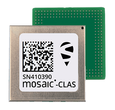
The mosaic-CLAS receiver is a GNSS module with a very small form-factor suitable for high-volume industrial applications.
The AsteRx-m3 CLAS is Septentrio’s best-in-class OEM board combining PPP-RTK CLAS with dual-antenna heading functionality.
The AsteRx SB3 CLAS features a ruggedized IP68 enclosure to protect it in harsh environments.
Septentrio is simultaneously offering various receiver types to the Japanese market ensuring an optimal match between products and customer needs in various applications including robotics, precision agriculture, construction, machine control and UAV.
“We are very pleased to jointly develop CLAS software on a new GNSS module, mosaic-CLAS,” emphasized Takahiro Yamamoto, director, GNSS Solution Business Center at CORE Corp. “This receiver puts CLAS GNSS technology on par with regular RTK receivers in terms of size as well as price. We believe that the realization of CLAS on the Septentrio mosaic platform will significantly promote the use of new QZSS services for industrial applications.”
“The launch of our new module and OEM board with CLAS support opens up new markets and use cases, which will benefit from centimeter-level positioning with fast acquisition time,” commented François Freulon, head of Product Management at Septentrio. “This launch demonstrates the technological leadership of Septentrio and our ability to provide dedicated solutions embedding L6 bands for the Japanese market.”
The CLAS PPP-RTK is the latest generation of GNSS correction services, combining near-RTK accuracy and quick initialization times with the broadcast nature of PPP. Receivers with built-in CLAS functionality offer sub-decimeter positioning accuracy right out of the box. Corrections for high-accuracy positioning are received directly from satellites, reducing the need for additional base stations or service subscriptions.
Find out more about PPP-RTK and other positioning correction methods in the insight article GNSS Correction Demystified.
In our 11th annual Simulator Buyers Guide, we feature simulator tools, devices and software from 11 prominent companies that aid GNSS receiver manufacturers in product design.
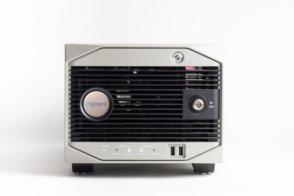
Alternative RF Navigation Simulator (Photo: Spirent Federal Systems)
New Alternative RF Navigation Simulator. Authorized users of Spirent’s alternative PNT simulation system can generate alternative RF navigation signals individually or concurrently with GNSS signals.
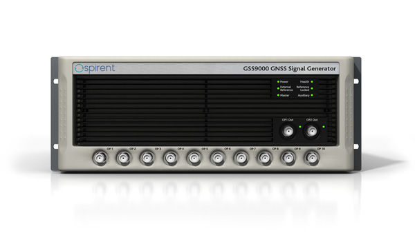
GSS9000. The GSS9000 Series multi-frequency, multi-GNSS RF constellation simulator is Spirent’s most comprehensive simulation solution. It can simulate signals from all GNSS and regional navigation systems and has an unrivaled update rate of 2 kHz (0.5 ms), enabling ultra-high-dynamic simulations with accuracy and fidelity. The GSS9000 supports M-code, Y-code, alternative PNT and non-GNSS sensors, and comes with built-in jamming, spoofing and flex power.
SimMNSA. Spirent Federal has the first fully approved MNSA M-code simulator. Authorized users of the GSS9000 series of simulators will be able to utilize the advanced capabilities of SimMNSA to create robust military GPS user equipment (MGUE) solutions.
Spirent GSS9000 Series constellation simulator (Photo: Spirent Federal Systems)
CRPA Test System. The CRPA Test System is scalable, testing antennas from 4 to 16 elements and beyond. More than 1,000 independent GNSS, jamming and spoofing signals can be generated/simulated across a phase-calibrated precise wavefront.
SimINERTIAL. Supporting the leading embedded GPS/inertial systems (EGI) and inertial measurement units (IMU), SimINERTIAL enables the controllable generation of inertial sensor outputs, synchronous with simulated GNSS, to test integrated GPS/inertial systems in the lab.
Anechoic Chamber Testing. Spirent’s GSS9790 multi-output, multi-GNSS RF constellation wavefront simulator system can be used in both conducted (lab) and radiated (chamber) conditions.
Mid-Range Solutions. Spirent offers solutions for every application and price point. The GSS7000 multi-constellation simulator provides an easy-to-use solution for GNSS testing that can grow with users’ requirements. The GSS6450 RF record-and-playback system enables replay of real-world GNSS tests in the lab.
Based on the Skydel GNSS Simulation Engine, Orolia’s advanced and essential GNSS simulators offer a wide breadth and depth of tools to test mission-critical positioning, navigation and timing (PNT) applications and scenarios.
Skydel Simulation Engine. The highly flexible, high-performance Skydel Simulation Engine transmits GNSS signals in real time to many kinds of software-defined radios. Skydel uses graphics processing units (GPUs) to compute the digital GNSS signal of all simulated satellites, easily scaling from simple to complex use cases. Skydel simulates civil signals from global and regional navigation satellite systems with a 1000-Hz update rate, many kinds of GNSS receiver trajectories with high dynamics, and advanced jamming and spoofing. The Skydel ecosystem also includes features such as open-source plug-ins and API, and the ability to create custom signals. The custom-signal feature allows users to experiment with new signals, such as navigation from low-Earth-orbit satellite systems.
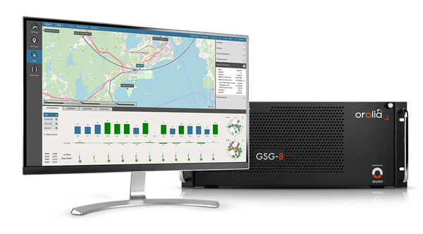
GSG-8. A scalable software-powered turnkey simulation solution, GSG-8 is configurable to meet virtually any testing requirements. It can support multi-constellation, multi-frequency and hundreds of signals with a 1000-Hz iteration rate. This advanced hardware platform is suitable for space trajectories, custom PNT signals, hardware-in-the-loop, multi-antenna simulation, and more. Encrypted EU signals will be available soon.
Skydel CRPA Testing. With self-calibration, integrated advanced jamming and spoofing, and the ability to generate thousands of signals, Skydel CRPA test systems provide everything needed to test CRPA systems, with a focus on ease of use and the testing experience from the user point of view. Two flexible configurations, Skydel Anechoic and Skydel Wavefront, have been carefully designed to provide the advanced simulation features required for CRPA testing in a well-thought-out package. Both provide COTS hardware benefits: configuration flexibility and cost-effectiveness.
GSG-5 and GSG-6. Orolia’s essential simulation platform is a proven, cost-effective simulation solution. Combined with the freely available StudioView software, these simulators provide high-end capabilities in a standalone, portable system that allows operation via a front panel interface. GSG-5 and GSG-6 are available with support for multi-frequency and multi-constellation GNSS signal simulation, pre-built scenarios and test packages, and the features neded to integrate it into ATE systems.
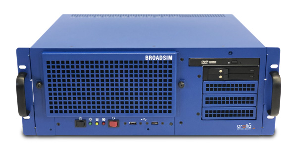
BroadSim 4U, Advanced NAVWAR simulations, MNSA and Y-Code (Photo: Orolia)
Advanced GNSS Simulation for Government & Defense
BroadSim
Powered by the Skydel Simulation Engine, BroadSim provides superior NAVWAR performance, sharing the same benefits and key features of its software-defined platform.
Key Applications
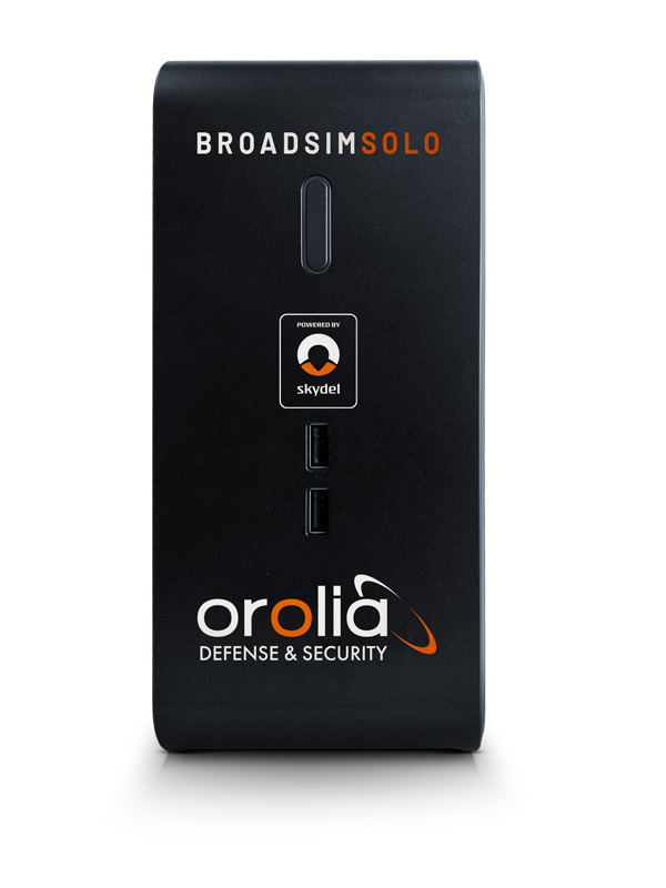
BroadSim Solo: Multi-GNSS simulations on the desktop. (Photo: Orolia)
MNSA M-Code. BroadSim offers a fully flexible implementation of the Modernized NavStar Security Algorithm, giving you full control over scenario settings with the real encryption used on the M-code signal. Any aspect of your scenario can be changed, such as time, date, location, constellation, downlink data, signal configuration, and visible satellites. It is security-approved by SMC Production Corps and shipping as soon as today.
CRPA Testing. BroadSim leverages Skydel’s CRPA testing solution to up the ante for demanding NAVWAR scenarios. BroadSim Anechoic allows you to test an entire system as-is. Skydel auto- calibrates the system, maps the antennas, and is designed to streamline chamber setup and reduce hardware. Broadsim Wavefront tests the antenna electronics, prioritizing the ability to have dynamic trajectories and allowing you to model any scenario with an unlimited number of interferences. The system is scalable from 4 to 16 elements, is phase coherent, performs real-time automated phase calibration, and has built-in jamming and spoofing.
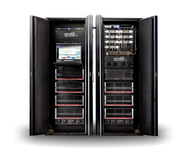
BroadSim Wavefront: Phase-aligned NAVWAR simulator for CRPA (Photo: Orolia)
Advanced Jamming and Spoofing. With Advanced Jamming, users can add ground- and space-based emitters to scenarios, generate an unlimited number of jamming signals on 1 RF output, and simulate flight profiles where interference power levels at the UUT dynamically change depending on the scenario motion. With Advanced Spoofing, users can simulate multiple spoofers simultaneously. Each spoofer can generate any GNSS signal and has an independent trajectory and antenna pattern. Signal dynamics between each spoofer and receiver antenna are automatically determined so no time is wasted.
More Features. Inertial and alternative RF navigation, built-in Flex Power, real-time performance with ultra-low latency of 5ms, high dynamics, terrain modeling, and RMF STIG compliance.
Test Anywhere with LabSat 3 Wideband and SatGen Simulation Software
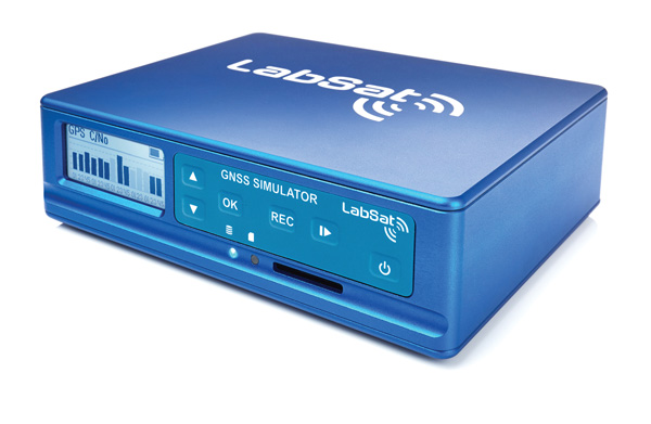
LabSat 3 Wideband. The LabSat 3 Wideband is a compact yet powerful multi-constellation and multi-frequency GNSS testing solution. The easy-to-use, one-touch record-and-replay function provides an efficient way to test and develop GNSS-based technology without the cost and limitations of live-sky signals.
It is lightweight and portable, enabling easy collaboration with colleagues by sharing scenario files over the internet, and making it a suitable test partner for remote working. Additionally, the removeable solid-state drive (SSD) of up to 7 terabytes and a two-hour runtime provided by an internal battery is ready for field testing in any environment.
LabSat 3 Wideband can record and replay up to three different channels at 56-MHz bandwidth across all major constellations and signals, including:
GPS: L1/L2/L5
Galileo: E1/E1a/E5a/E5b/E6
GLONASS: L1/L2/L3
BeiDou: B1/B2/B3
NavIC: L5/S-band
QZSS: L1/L2/L5
L-band correction services including SBAS
2x CAN and 4x digital input channels tightly synchronized with GNSS data
future signal launches are also supported, including L2C, L5 and L1C
SatGen Simulation Software. SatGen software allows users to quickly create bespoke, accurate scenarios with their own time, location and trajectory that can be replayed via a LabSat GNSS simulator.
The latest version of SatGen can be used to create a single scenario containing all the upper and lower L-band signals for GPS, Galileo, GLONASS, BeiDou and NavIC.
When getting the job done right the first time — and every time — matters, CAST Navigation’s suite of simulator solutions delivers precision, accuracy and repeatability. From simple integration testing to complex mission simulations, CAST Navigation solutions scale to meet user requirements.
Powered by multi-frequency, multi-constellation GNSS and interference signal-generation technology, CAST Navigation simulators provide coherent, highly accurate and fully programmable signals. Advanced, configurable vehicle trajectory capabilities meet project requirements ranging from antenna testing to simulations of squadrons maneuvering in contested environments.
Intuitive Graphical Interface. A comprehensive and intuitive graphical interface unifies all simulator capabilities so users can configure complex simulation scenarios quickly. For example, CAST Navigation simulators can model many vehicle types with static and dynamic motion profiles: airborne, terrestrial, aquatic or space-based. Using configured scenario profiles or vehicle truth data, CAST Navigation simulators create high-dynamic, 6-DOF real-time trajectories.
High-Fidelity Simulations of Real-World Conditions. CAST Navigation solutions can reproduce terrain, sea-state and atmospheric effects to simulate missions with high fidelity. Jamming capabilities recreate natural, urban and hostile interference to produce precisely controlled waveforms with high output power and exceptionally low intermodulation noise.
Multi-Frequency, Multi-Constellation Simulations. The GPS/GNSS simulators generate accurate, programmable signals to each antenna element with up to 16 satellites in view from as many as four constellation types. GPS simulations can generate any positioning signal (C/A-code, P-code, Y-code, SAASM, M-code AES and M-code MNSA).
Modular, Scalable Solutions. Proprietary synchronization technology lets CAST Navigation configure customer solutions with multiple simulator capabilities — GPS/GNSS, inertial, jamming, and CRPA — to meet specific project needs. As those needs evolve, these solutions do not become obsolete. Rather than replace a functioning system, customers can rely on modular architecture to meet their new requirements.
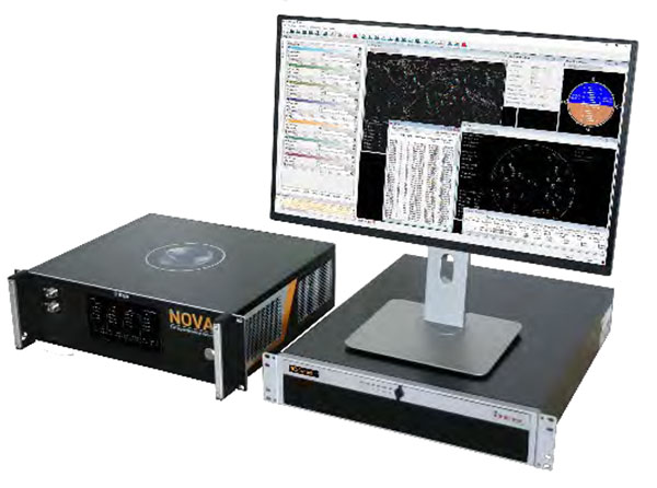
The NCS NOVA GNSS simulator is a high-end, powerful and easy-to-use satellite navigation testing and R&D device. It is fully capable of multi-constellation and multi-frequency simulations for a wide range of GNSS applications. It is one of the leading solutions on the market, providing multiple GNSS frequencies in one box.
Because of the modern and flexible software-defined radio (SDR) design of this simulator, testing requirements will be met with the minimum of equipment, facilitating logistics and reducing the cost of ownership. The innovative multi-constellation and multi-frequency simulation capability sets new standards in the field of GNSS simulation in terms of fidelity, performance, accuracy and reliability. Designed to deliver maximum flexibility, users are no longer faced with configuration limitations.
The NCS NOVA GNSS simulator is also able to coherently generate GNSS RF signals on two independent RF outputs simultaneously. The user may freely allocate GNSS signals and RF channels to each of the RF outputs. This feature allows simulation of GNSS signals at two antenna locations simultaneously (this could be two antennas on a vehicle, two separate vehicles maneuvering independently, or a static location plus a mobile unit).
A new key enhancement to the NCS NOVA GNSS simulator is comprehensive support of new Galileo OS signal message improvements on E1B. By enabling real-time simulation of the Galileo OS message improvements, the NCS NOVA expands a user’s Galileo signal capability.
In the future, the NCS NOVA also will fully support the new Galileo E1B OS Navigation Message Authentication (OS-NMA) and Galileo E6B High Accuracy Service (HAS) capabilities.
The NCS NOVA GNSS simulator is the first choice in signal simulation for a wide range of applications including space, aviation, automotive (including autonomous driving testing) and many others.
About IFEN. IFEN is a leading provider of GNSS navigation products and services. Its technology portfolio includes GNSS RF-signal simulators, GNSS software receivers, simulation and data processing tools. IFEN’s outstanding satellite navigation expertise is provided to customers for services including GNSS system studies, research and development of navigation and integrity algorithms, design and development of GNSS software and hardware, on up to engineering of turnkey facilities and systems.
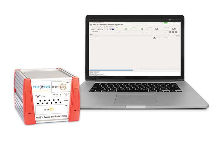
The MGSE product family creates a versatile GNSS test and simulation environment that improves the development, qualification and certification process of GNSS receivers within development phases and for validation and certification in end-to-end tests.
MGSE enables mobile and stationary interference monitoring, for example, for protecting critical infrastructures. It can be used for interference mitigation if combined with TeleOrbit’s GNSSA-6E (six-element antenna array) or its GNSS DCP (dual circularly polarized)antenna.
With MGSE REC-REP 2.0 users can, among other tasks, record Galileo PRS signals in a real user environment and replay them for Galileo PRS receiver testing.
MGSE SIM-REP supports the development of software-defined radios/receivers or specialized algorithms by creating a simulation environment that provides the possibility and flexibility to use synthetically generated GNSS data and recorded real-world samples.
For jamming and spoofing test and evaluation, TeleOrbit offers a sophisticated solution based on the MGSE simulation, recording and replaying product family. For spoofing mitigation, the GOOSE-OSNMA receiver platform is available.
Technical Background
The multi-band RF front-end (MGSE REC) receives the GNSS RF signals in different frequency bands simultaneously to obtain digital IF data, which can be used for GNSS multi-system signal analysis and comparison. All GNSS L-band frequencies and the NavIC S-band are supported.
The MGSE Replay Unit includes a flexible multi-band RF replay device that streams simulated and recorded raw IF data to a digital baseband output or to an analog RF signal. Up to two independent RF channels and up to four GNSS signals (L1, E1, B1, G1) can be provided.
GOOSE is a powerful yet compact GNSS receiver lab and the rapid prototyping solution for leading-edge GNSS receiver development.
The GNSSA-DCP (dual circularly polarized antenna) receives RHCP and LHCP signals simultaneously (full L-band). It clearly detects signals which have been corrupted by diffraction and reflections.
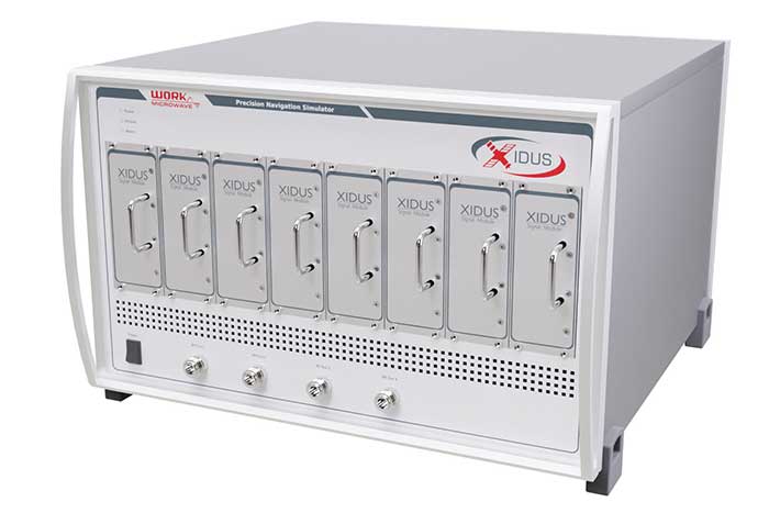
WORK Microwave’s Xidus is well-known for meeting all requirements regarding multi-GNSS; for its multi-frequency and multi-RF signal generation; for its innovative Signal Extension and Enhancements (SEE) technology; for its advanced customization and configurability; and for world-class remote support with updates, training and even scenario execution.
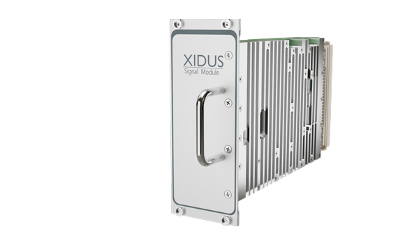
Xidus Signal Module
Compact and powerful, the Xidus Signal Module provides new capabilities of signal generation. Users can perform rigorous and extensive testing of present and future positioning systems when conducting navigation research or developing products.
Possible applications: pseudolite generation, massive multipath or navigation signal generation on various orbits.
Extensive increase of supported channels: >250.
Unlimited number of multipath channels with delay >3,000km.
Interference signal generation on up to four independent frequencies.
Acts as a software-defined radio (SDR) to replay signals.
Xidus-648 (Photo: Work Microwave)
Xidus Hardware Series
Xidus-424 GNSS Simulator
Up to 4 signal modules
2 RF outputs
Wide dynamic power range
Xidus-648 GNSS Simulator
Up to 8 signal modules
4 RF outputs
1,000 Hz update rate
Xidus-Studio Client Software
Xidus-Studio provides a user-friendly graphical interface to configure any GNSS scenario. Its advanced and outstanding features include:
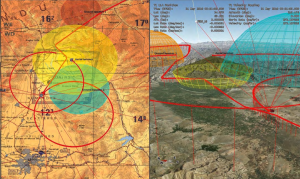
QA707 is the cutting-edge solution for global threat GNSS awareness and management. It is a GNSS simulator specifically designed to test cyber-attacks and authentication, and includes the simulation of GNSS interference, deception, jamming, spoofing and advanced cyber-threats such as data- and code-level attacks.
The high flexibility in the creation of the scenarios and the definition of the type of attacker allow cyber-threat and vulnerability testing for several applications,These applications may include, for example, autonomous driving and vehicle tracking, aeronautics and high dynamics applications, space GNSS receivers and timing.
OSNMA Support. The Galileo Open Service Navigation Message Authentication (OSNMA) simulation is an opportunity to test the new Galileo data protected service against several known vulnerabilities in GNSS applications. The OSNMA simulator is also available as a standalone tool, allowing the generation of OSNMA data that can be used with third party simulators.
PC-capable. QA707 runs on a standard PC. It is compatible with several third-party hardware RF up-converters, including National Instruments’ USRP. Additionally, it can support customer-specific hardware through the hardware API interface.
QA707 Main Features
Multi constellation (currently GPS L1, GALILEO E1, SBAS L1)
Galileo OSNMA
RF simulation, binary file dump, signal record and replay
Support to SDR platforms and open API for custom RF upconverters
Runtime streaming of scenario information over UDP (motion, channel data)
Data level cyber-attacks
Accurate spoofing signals control, trajectory spoofing, signal replay attacks
Narrow band, wide band, frequency modulated jamming
Integrity threats (on request): evil waveform, erroneous ephemerides, code/carrier divergence, low satellite signal power, excessive range acceleration
The StellaNGC all-in-one testing platform. (Photo: M3 Systems)
High-end multi-constellation and multi-frequency GNSS Simulator and Record & Playback
M3 Systems offers a fully integrated all-in-one testing solution for GNSS. Thanks to a versatile SDR approach, StellaNGC provides on a single HW platform GNSS simulation and GNSS record & playback functionalities. It answers user challenges from aerospace, defense, ground transportation and telecommunication fields when testing the PNT functions of their GNSS-based systems.
StellaNGC Plug & Play. This fully scalable and customizable simulator is based on a layered architecture to provide PNT data to the user at different levels (RF, IQ, GNSS raw data, trajectory).
Based on COTS platforms from National Instruments (NI), StellaNGC P&P allows the simulation of civil signals from GNSS as well as ground-based and satellite-based augmentation systems. It covers terrestrial, aerial and spatial trajectories (including high dynamics). It also enables assessment of GNSS solution robustness with jamming, meaconing and spoofing capacity.
Multi-antenna (CRPA applications) and multi-trajectories
Jamming and spoofing simulation
Cm-level positioning
Low latency HIL simulation
SBAS and RTK augmentation systems
3D multipath generation
IMU sensors modelization
Configuration of all scenario parameters
Signal control during run-time
Intuitive and easy to use GUI
StellaNGC Record & Playback. As a complement to simulation, StellaNGC RP allows test and validation of PNT functions through high-fidelity record-and-playback of GNSS signals. It allows recording by selection of a center frequency (65 MHz–6 GHz) or with a predefined list of GNSS frequencies for each of its 4 RF channelw, with a bandwidth of up to 120 MHz.
StellaNGC R&P Main Features
Multi-bands record & playback
Programmable center frequency and bandwidth
Single or multi-channel (up to 4) simultaneous records
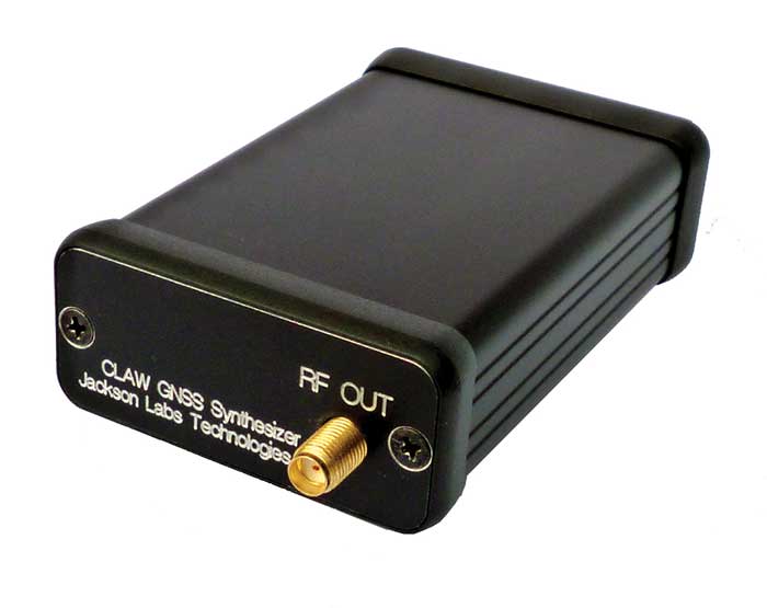
The 18-channel miniature full-constellation CLAW GPS Simulator is a fully self-contained, low size, weight, power and cost (SWaP-C) miniature GPS simulator. It is very popular in manufacturing environments as well as R&D applications that require consistent and repeatable local GNSS signals at low price points.
The CLAW simulator does not require external computers for processing and control — it works fully self-contained by simply applying power, and storing location/time/date data in internal non-volatile memory, or by storing complex vector data to simulate highly dynamic scenarios. The CLAW also can be used to transcode NMEA or SCPI position/velocity/time (PVT) data into GPS RF signals. For 2022, JLT added driver support for a large number of additional GNSS front-end receivers when using the hardware-in-the-loop (transcoding) feature of the unit to, for instance, transcode from one GNSS system to another.
JLT offers an easy-to-use, highly configurable and cost-free SimCon Windows application program that is downloadable from the JLT website. SimCon allows random scenario generation and is thus usable to simulate leap-second events, Week 1023 rollover events, or any other GPS live-sky scenarios, including highly complex yet easy-to-create dynamic vector simulations.
For authorized U.S. government users, a version that does not have altitude and velocity limitations is popular for low-Earth-orbit (LEO) simulations. Multipath simulation allows use of the entire 18-channel simulator capability.
The unit can be field-upgraded with an easy-to-use in-field software upgrade feature. The CLAW is also very useful in GNSS receiver sensitivity testing for R&D or mass-production assembly lines as it allows accurate control of RF output power ranging from –100 dBm to less than –130 dBm with 0.1-dB resolution and typically better than 1-dB accuracy over the controllable power range.
The CLAW GPS Simulator also has a built-in RF signal generator with sweep, CW and random noise functions that are useful in simulating GNSS jamming scenarios, as well as GPS spoofing scenarios. The simulator comes in an FCC-certified metal desktop enclosure with numerous accessories.
The CLAW firmware has been updated to allow live-sky almanac and ephemerides to be automatically uploaded from various externally connected GNSS receivers. This makes simulations using real-time live-sky constellations (such as used in simulating spoofing attacks) an easy task. A free firmware update is available from JLT.
High-end GNSS simulation solutions for R&D, integration and product testing
Syntony GNSS specializes in GNSS/PNT software-defined receiver (SDR) technologies, operating from receivers to test and measurements solutions. Its products and solutions address multiple markets and use cases in the space, defense and transportation industries.
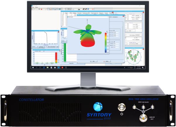
Constellator. (Photo: Syntony)
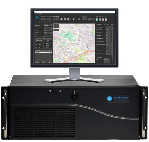
Constellator GNSS Simulator. Scalable, cost-effective, and high-fidelity SDR software-based platform supporting multi-constellation signals and frequencies (open, restricted and custom), hundreds of signals at 1-kHz iteration rate at zero effective latency, space trajectories and high dynamics. Multiple upgradable hardware configurations are available.
Constellator CRPA. Synchro-phase SDR by design, advanced jamming and spoofing, thousands of signals, 4 to 16 elements.
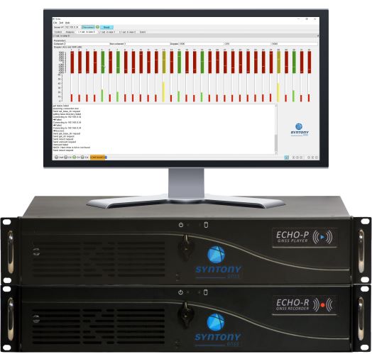
Echo. (Photo: Syntony)
Echo Recorder & Replayer. High-fidelity record-and-replay devices characterizing group-delay, scintillation, and jamming and spoofing interference, from space to ground market segments.
3 RF channels of 200Mhz sampling rate
16 bit I/Q
Up to 1.6 GB/s write/read speed.
SubWAVE manager. (Photo: Syntony)
SubWAVE GNSS/GPS Coverage Extension. Universal and seamless GPS/GNSS coverage extension for rail, road and mining infrastructures. SubWAVE signals are natively compatible with every GNSS-enabled device, and the solution uses existing telecom infrastructure to broadcast GNSS signals.
Flanders uses Septentrio receivers to guide automated blasthole drills, such as at this South African mine run by AngloGold Ashanti. Photo: Anglogold Ashanti/Flanders
Flanders, a U.S.-based company with expertise in electrical machinery and control systems, has developed its proprietary ARDVARC advanced drill-rig control system to control mine-drilling machines, making them safer and more efficient. The drill rigs equipped with ARDVARC create holes with centimeter precision. This ensures optimal rock fragmentation, simplifying and expediting subsequent jobs such as stone extraction and removal.
Mines close to the poles or to the magnetic equator, such as those in the Amazon, are challenging for GNSS receivers because they tend to experience the most intense ionospheric scintillations, resulting from rapid fluctuations in the electron density in the ionosphere. These scintillations affect GNSS signals that travel from space to Earth, causing degradation of positioning accuracy or even positioning loss.
To address this challenge, ARDVARC uses Septentrio AsteRx-U GNSS receivers. They are housed in a tough IP67 enclosure and run Septentrio’s proprietary GNSS+ algorithms including IONO+, which ensures high-accuracy positioning even during ionospheric scintillations.
ARDVARC’s benefits include a faster drill cycle time, increased drill hole location precision, increased drill-rig component operating life, improved fragmentation and greater operator safety. The system is available in several levels.
The Intelli-rig manual control system also delivers data on the position of each blast hole, the machine operation and the drilling conditions; it incorporates mine-planning functionality using the mine’s existing or Flanders’ optional GPS equipment.
One-touch converts a manually operated machine to one operated with a single touch, increasing productivity. Once the machine operator positions the drill rig over the desired target, One-touch initiates the automated drilling process, which includes machine leveling, hole collaring, drilling to elevation and angle, rod handling, bit retraction and jack reset.
The fully autonomous drilling solution removes the operator from the cab, allowing one operator to monitor multiple drilling operations from a safe distance. The solution increases productivity by enabling drilling during blasting and shift changes. It uses Flanders’ HazCam to monitor the surroundings, preventing the drill from operating in unsafe conditions.
A SolarCleano F1A robot tackles a tough cleaning challenge on a solar farm in Saudi Arabia. (Photo: SolarCleano)
SolarCleano, based in Garnich, Luxembourg, makes robots that clean large solar panel installations using GNSS receivers and corrections from Swift Navigation. We asked Christophe Timmermans, SolarCleano’s managing director, a few questions about its technology.
How often do solar panels need to be cleaned?
For decades, it was believed that solar panels did not need to be cleaned due to their angle to the ground and rain. Nowadays, however, the cleaning of solar panels is widely accepted as necessary to optimize a plant’s return on investment (ROI).
How much time per sq. meter do your machines take to clean solar panels?
To provide the fastest possible ROI to our customers, we developed a range of robots to best address the needs of various solar plant layouts. A large utility-scale project with high level of soiling losses in a desert environment will need a very fast and reactive cleaning solution such as our SolarBridge B1, which can clean 24/7/365 fully autonomously. The most suitable solution for a farm rooftop in Germany that needs to be cleaned three to four times a year might be our F1 model, which can clean the equivalent of up to two soccer fields a day. It is designed for rooftops, floating panels and mid-size plants up to 50 MW. While the speed of cleaning is a very important variable, the quality of cleaning is often considered as the driver to performance, which is why we propose different types of brushes depending on the soiling types. Plus, the robot speed can be modified according to the soiling level.
Why do robots need GNSS receivers to clean solar panels?
Moving on inclined, wet glass surfaces makes odometry unreliable because robots might occasionally slip. Therefore, GNSS is the most reliable way to continuously monitor their exact position. Our robots also need path planning because they cannot operate randomly like lawn mowers. Safety is obviously a major concern; we need a very high localization accuracy to ensure that robots don’t fall off the panels. Finally, the largest solar plants are developed in dry, remote locations with high irradiation such as the Sahara, Atacama and Australian deserts. GNSS allows us to have very accurate localization even in those remote areas. In addition, this solution can easily be installed on already-existing solar plants with little capital expenditure.
What spatial accuracy requirements do the robots have for this task?
Safety is our absolute priority. Therefore, our robots need an accuracy of less than 3 cm. They also need to be aware, in real time, of changes in their surroundings, such as maintenance teams, animals and uneven ground.
On large solar farms, GNSS receivers always have a clear line of sight to the satellites and do not suffer from multipath. So, what are the key technical challenges?
Our robots have the additional advantage that they do not need to drive very fast. However, we need to manage fleets of robots on the other side of the world in regions difficult to access and with harsh weather conditions, such as very high or low temperatures and the accumulation of dust behind panels due to air vortices. We need to be able to perform remote maintenance and solve any issue from our control center in Luxembourg. These challenges make our robots increasingly robust. With a current fleet of more than 300 robots around the world, we collect lessons every day to ensure a greater reliability for our upcoming generations of robots.
Why did you choose to partner with Swift Navigation?
We share a vision with Swift: “Accessible automated solutions serving sustainable goals.” We also share other important values, such as “iterate quickly” and “focus on what matters.”
ComNav’s high-accuracy PileMaster sped construction of the Aarah Resort in the Maldives. Photo: LANKA Foundation and Piling Services Pvt. Ltd.
The construction of the Aarah Resort in the Maldives involved building 64 luxury water villas and 12 beach buildings on a shallow-water area with about 1,400 piles. LANKA Foundation and Piling Services Pvt. Ltd. was able to complete the piling project in only 32 days by using a high-accuracy piling solution from ComNav Technology Ltd.
The traditional piling approach requires many surveyors to stake out the positions of the piles underwater in advance. Not only is this process labor-intensive, it also creates a real-time problem: even if the coordinates are measured accurately by lofting, the primary coordinate markers are soon out of position due to the movement of the piling machines. The stakeout’s accuracy is also threatened by strong waves, ocean currents and coral reefs. Furthermore, in the subsequent piling process, the piling accuracy is reduced due to artificial aiming. During the whole process, surveyors must work in the water and fix the piles at short range, which is dangerous. For these reasons, the traditional piling approach is a low-efficiency, high-cost and high-risk operation.
Photo: Google Earth
ComNav’s professional positioning solution for high-accuracy piling provides a 9-inch high-resolution tablet with an integrated GNSS receiver, a T300 GNSS receiver as the base station, and two AT340 antennas with magnetic mounts combined with PileMaster software. Its integrated GNSS receiver tracks GPS, GLONASS and BeiDou signals, enabling the system to work even in challenging environments. The system can acquire real-time kinematic (RTK) corrections via an internal UHF transceiver from the T300 receiver or connect to a local continuously operating reference station (CORS). Moreover, PileMaster is designed with an intuitive interface with clear element-management capability, supporting import of up to 10,000 points from Excel, TXT and CAD formats to meet the specific demands of a high-accuracy piling project.
Compared to the traditional piling method, ComNav’s intelligent control system for piling is an all-weather, high-accuracy solution with the additional advantages of being widely compatible and easy to manage. Through software system control and real-time processing and display, it can greatly reduce the number of surveyors required on-site. The system can guide users to the location, shorten the construction period, save construction costs, and enable intelligent visualization and monitoring to ensure high-precision construction work.
After a first successful application in 2017, Foresight Surveyors Pvt. Ltd, ComNav’s local partner in the Maldives, used the solution in many projects, including construction of the Kunaavashi Resort & Spa in 2018 and the Kuda Villingili, Dhigufaru Island and Maniya Faru resorts in 2019.
A mining road-train loaded with ore passes through an outback town. A Hexagon system will guide autonomous movement of similar heavy vehicles. Photo: BeyondImages/iStock/Getty Images Plus/Getty Images
Hexagon’s Autonomy & Positioning and Mining divisions recently partnered with Mineral Resources Limited (MRL), a mining services company, to develop an automated road-train solution for deployment on MRL’s haulage fleet over the next two years. The solution integrates drive-by-wire technology with an autonomous management system to orchestrate vehicle movement in road-train haulage to improve safety, productivity and sustainability. We asked Lee Baldwin, the director of Hexagon’s Autonomy & Positioning division, a few questions about the system.
What does an automated road-train do?
It is for haulage on roads hundreds of kilometers long. It first will be used to move ore from a mine processing facility in the Pilbara region of Western Australia, about 1,200 kilometers north of Perth, to Port Hedland, where it is loaded on ships bound for Asia for use in steel mills. Typically, this is done using either rail or a road train, which is a highway truck pulling multiple trailers. Today, a person drives a road train.
What motivated this project?
Mines have difficulty finding drivers for mining trucks and road trains because the mines are very far away from the nearest city, Perth, so they must fly workers in and out, which is very costly. Many of them are on 10-day shifts. Also, there are safety concerns.
How does an automated road-train work?
It requires three typical subsystems that you would have on any autonomous vehicle. The first one is positioning, including redundant GNSS receivers with our TerraStar correction services. The second is a perception system for collision avoidance, using our HxGN MineProtect Collision Avoidance System. The third one is route planning. We will start by platooning, with a driver in the first truck, which will be followed by three unmanned ones, each towing multiple trailers. Each truck will have the positioning, perception and route-planning systems. Later, we will achieve full autonomy by removing the driver from the lead vehicle.
How will the transfer at the mine work?
At a mine site, the road train will be commissioned in a sequestered area, then sent to a loading area where it will be loaded with ore, either automatically or by a manned wheel loader. Next, it will travel 200 kilometers to the port, where it will dump the ore. Finally, it will be decommissioned and queued up for the return journey.
Which parts are already in place and which ones are still being developed?
At Hexagon, we are already putting technology in manned mines. For example, we already have the collision-avoidance system, a fleet management system, and some sitewide planning systems. However, the trucks that the customers are choosing will have to be converted to be drive-by-wire to accommodate our autonomy system. They will use two PwrPak7 GNSS receivers and the TerraStar correction service.
On a project on the Butterfield Landfill — about 45 miles south of Phoenix, Arizona — Buesing Corp. needed to excavate and haul 1,850,000 cubic yards of dirt from a landfill more than 60 feet deep while grading the slope, basin and stockpile; inserting storm drains; and making an operations layer.
Buesing, founded in 1965, specializes in modeling and building complex underground systems in challenging conditions. It had four months to complete the initial mass grading, with another month for shaping the stockpile and a final month for the operations layer and piping. The mass grading of the site required an accuracy of plus or minus one tenth of a foot in a landfill with 4:1 slopes and a slope length of 300 linear feet, and the operations layer had to be two feet thick. The project also required installing storm drain inlets, flow lines, and outlets to grade.
To remain on schedule, the project required moving large quantities of soil quickly and efficiently, as well as adjusting grading models to incorporate design updates and changes while in production. “We used DTMs and orthophotos collected with our UAV to track progress quantities and adjust the stockpile model to minimize haul distances and slope rework as well as maintain proper drainage and control of stormwater,” said Rio Byman, Buesing’s GPS manager, who is responsible for building 3D models and managing the maintenance, calibration and updates for the company’s machine control (MC) solutions.
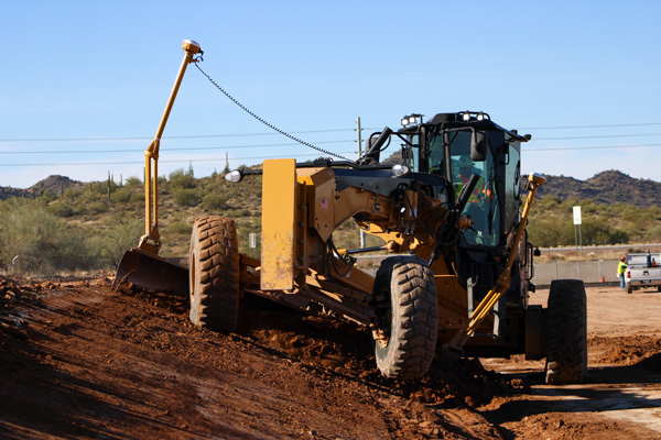
A caterpillar CAT14M3 motorgrader is guided by Trimble’s dual-mast Earthworks system. (Photo: Trimble)
For this project, the company used heavy equipment both with and without MC, including blades, excavators and dozers with MC, along with GNSS-based grade checkers to control the earthmoving operations. Specifically, Buesing, which started converting its equipment to Trimble around 2018, used the Trimble Earthworks Grade Control Platform and the Trimble GCS900 Grade Control System on the site and Trimble Business Center at its office.
Buesing works in a variety of market segments for public and private entities in seven states, though it performs most of its work in the Phoenix metropolitan area. Key to its success has been an emphasis on skilled crews, continuous training and technology. In fact, Buesing was one of the early adopters of machine control in 2006. “A decade ago, the technology was pretty rudimentary, which limited adoption,” Byman said. “That’s changed a lot in recent years, particularly in the ease of use and flexibility. Today, grade control is an integral part of the company’s ability to build ever-more-complex solutions in even more challenging site and soil conditions.”
The company started with the Trimble GCS900 on single-mast and dual-mast blades, excavators and dozers. It has since moved to the Trimble Earthworks Grade Control Platform along with Trimble Business Center for managing 3D models. Working closely with SITECH Southwest, Buesing has gone from six machines with grade control to more than 20 in just five years. The company relies on grade-control solutions on its excavators, dozers, motor graders and scrapers, and has used them on projects of every scope and scale, though their value is most evident on urban high-rise excavation.
“It takes time for operators to gain faith in the data, and know that the machine will excavate efficiently and accurately, whether building pads or cutting basements,” Byman said. He believes that improved productivity in the field comes with trust in the technology.
Using Trimble Earthworks’ Autos mode, the software controls the implements while the operator controls the machine’s direction and speed for consistent, high-accuracy finished grade in much less time than it would take without automation. “On any jobsite, the operators have to be aware of everything around them, as well as what’s going on with the blades or scrapers,” Byman said.
“With Autos, they’re able to focus on what’s going on around the job and plan for watering and other environmental conditions with confidence that the machine is digging to grade. This makes our jobsites more productive, safer and more efficient. We have happier operators who are excited to come to work with newer equipment.”
Lidar sensors that used to cost tens of thousands of dollars now cost only hundreds of dollars. With prices significantly decreasing, 3D sensors are more accessible than ever before. Now, what was once a niche technology exclusively for autonomous vehicles is being deployed globally to make places safer and smarter. Additionally, the industry is continuing to grow: market analysis firm Yolé estimates that the lidar industry will be worth nearly $4 billion by 2025, a 19% CAGR between 2020 and 2025.
While decreasing sensor prices are a critical factor in the proliferation of lidar, an arguably more significant development is the development of robust perception software that can track, identify and monitor with far greater accuracy and efficiency than ever before.
Effective 3D sensors, from lidar to radar and 3D cameras, require both hardware and software components. The hardware is critical to capturing data with high resolution and accuracy, while the software processes and comprehends the data, making them actionable. Essentially, software is the “brain” of sensors. Lidar, without equally strong perception software, is like an iPhone without iOS — inoperable and just a piece of machinery.
Today, at the confluence of these factors, we are beginning to see a proliferation of 3D perception applications beyond autonomous driving. Cities, security and retail are a few key sectors where I predict we will continue to see advancements over the next few years.
Making Cities Smarter
The steep drop in the cost of lidar sensors has made 3D sensors more accessible than ever. (Image: Seoul Robotics)
Today’s cities have a variety of challenges to address, from decreasing traffic collisions to reducing congestion, and we are witnessing municipalities leveraging lidar to collect critical insights into city safety and efficiency.
However, why are they turning to 3D solutions, specifically? Because they can capture the data necessary to make actionable changes. 3D sensors were developed to quickly track and analyze city surroundings for autonomous vehicles, so they are an effective way to ensure that vehicles are not veering into opposing lanes or traversing crosswalks already occupied by pedestrians.
Cities also adopt 3D applications because they can often address multiple challenges with one system. For example, a city may install a lidar system on an intersection to detect traffic violations, but the system can also capture data about pedestrian safety and traffic flow. These multi-benefit solutions are ultimately more cost-effective for cities because they eliminate the need to install multiple different solutions to solve these problems.
Creating Safer Spaces
Companies are turning to 3D data to create safer and more secure environments. (Image: Seoul Robotics)
From airports to museums, from stadiums to music venues, the market for 3D-based security solutions is vast. While each of these environments is unique in how it operates, they all rely on technology to ensure that areas are secure, visitors do not enter prohibited areas, and crowds are seamlessly moving through the space.
3D perception helps address these challenges by creating “zones” that can alert security systems if someone enters. Additionally, because 3D sensors can detect and track various objects, including humans, they are increasingly becoming a popular solution for crowd control. They can help venues monitor and address foot traffic, such as with security lines, and they can be valuable in the event of an emergency to ensure that an area is clear.
Beyond the tangible benefits 3D sensors bring to different venues, companies are turning to 3D data to create safer and more secure environments because they are more accurate and anonymous. Unlike traditional camera-based systems such as CCTV, which are often prone to false positives, 3D data are incredibly accurate and precise, so they are less likely to set off alarms unnecessarily. Additionally, 3D data do not include biometric information, so they address privacy concerns while still ensuring that areas are secure.
Building 3D Retail Environments
By implementing 3D-based solutions into a physical retail environment, companies can better understand how shoppers are moving through and spending their time in stores. They can glean insights into key metrics, such as:
How long are people in line?
What areas of the store are receiving the most traffic?
With what products are people engaging most frequently?
As one example, Mercedes-Benz has integrated 3D sensors into its showrooms in Korea, gaining fascinating insights into customer behavior. For example, they’ve discovered that nearly 60% of customers spend their time looking at the trunk space of SUVs, and that red is the most popular color.
As these solutions continue to become more sophisticated and accessible, we should expect to see them in more areas of our everyday lives. The future of 3D perception is exciting, and it will ensure safer, smarter and more efficient spaces — improving the quality of life.
HanBin Lee is CEO of Seoul Robotics, a 3D perception company specializing in lidar.
Currently, 37 Global Positioning System satellites are on-orbit, with 29 of them set healthy. The system continues to provide an average 48-centimeter position accuracy. Despite this achievement, the U.S. government — specifically, the Space Force — continues to modernize GPS’s space, control and military user equipment segments.
Modernization of the space segment is centered on the GPS III satellites, which provide up to eight times better anti-jam capability and a new L1C signal to improve user connectivity. GPS IIIF satellites, scheduled for delivery starting in early 2026, will add a search-and-rescue payload, a fully digital navigation payload, and greatly enhanced anti-jam capability for military operations.
Modernization of the control segment is focused on the next-generation Operational Control System (OCX), scheduled to become operational early next year. OCX will sport an updated architecture to provide enhanced command-and-control capabilities and enhanced cybersecurity. Despite the pandemic, all 17 global OCX monitoring station installations were completed last summer, and most of the remaining equipment was fielded by the end of 2021.
Twenty-four GPS satellites are broadcasting the military code (M-code). The Modernized GPS User Equipment (MGUE) program is developing military GPS receivers able to take advantage of these signals to improve defenses against spoofing and jamming while allowing navigation warfare operations.
On the civil side, GPS modernization will play a key role in the development of the Next Generation Air Transportation System and intelligent transportation systems. The Department of Defense coordinates its GPS activities with the Department of Transportation (DOT), the Federal Aviation Administration (FAA) and many other federal departments and agencies via the National Executive Committee for Space-Based PNT. The term “space-based PNT” refers to GPS, GPS augmentations and other GNSS.
However, this government-wide coordination and cooperation is contradicted by the stand of the Federal Communications Commission (FCC) on the matter of Ligado Networks’ applications to modify its license for terrestrial service, which it approved in 2020. The FCC’s decision is opposed by the executive branch, represented by the National Telecommunications and Information Administration (NTIA), and by 14 federal agencies and departments individually (including the departments of Defense, Transportation, State, Treasury, Justice, Interior, Agriculture, Commerce, Energy and Homeland Security), as well as by the National PNT Advisory Board and by most GNSS receiver manufacturers and aviation organizations. NTIA took the unprecedented step of filing a still-pending petition for reconsideration with the FCC. The concern is that Ligado’s proposed transmission power exceeds the thresholds established by the DOT’s April 2018 GPS Adjacent Band Compatibility study to protect GPS users from harmful interference.
So, the list of threats to GPS now includes solar flares, spoofing, jamming, “legal jamming” by Ligado, and the Russian government’s recent threat to destroy GPS satellites. Modernizing GPS must proceed hand-in-hand with protecting it.
ByBradford W. Parkinson Aeronautics and Astronautics Professor Emeritus (recalled) Stanford University
Brad Parkinson
We, of the PNT universe, have been hearing a rather continual message of doom from the media regarding the fragility of the GPS (or GNSS) signals. In a way, they are right. The received GPS signal is 1/10th of 1 millionth of 1 billionth of a Watt. It can be susceptible to jamming and spoofing.
In response, the U.S. government has sponsored major studies and some competitive tests of techniques to augment or possibly replace GPS. I applaud such queries, but also would strongly advocate more balance in efforts to increase robustness of positioning, navigation and timing (PNT).
Specifically, I argue for increased emphasis on well-known techniques that can greatly toughen GNSS receivers to both jamming and spoofing. Some of these techniques are deliberately denied to civil users by government policy.
Background
The PNT Advisory Board (PNTAB) is a panel of national experts who report to the PNT ExCom. The ExCom is comprised of the deputy heads of the nine U.S. government departments with the largest stakes in PNT. The PNTAB has a starkly simple and well-stated goal:
To meet its overarching goal, the PNTAB has developed a three-legged strategic framework, known as “PTA”: “We must protect, toughen and augment GPS to ensure that it continues to provide economic and societal benefits to the nation.”
Most current U.S. government efforts have been focused on the third of the PNTAB strategic legs: augmenting the GPS system. These system augmentations include: modernized Loran (eLoran), fiber-optic distribution of time, and ranging to low-Earth-orbit (LEO) satellites (particularly the swarms of communications satellites). In general, these system augmentations offer no hope of being equivalent to GPS in terms of availability and accuracy.
However, augmentations have the advantage of either being less vulnerable to interference, or highly proliferated in case of satellite outages. As supplements, or in an emergency, they can perform a very valuable role, but with nowhere near the equivalent performance of normally operating GNSS, which can routinely provide worldwide, 24/7 precisions better than decimeters in the dynamic real-time kinematic (RTK) mode. In the United States, GPS also offers continuous, real-time integrity assessments courtesy of the FAA1. Europe has a similar, compatible integrity system called EGNOS, and there are other regional system augmentations.
In summary, the current PNTAB assessment regarding these substitutes is:
“No current or foreseeable alternative to GNSS (primarily GPS) can deliver the equivalent accuracy (static down to millimeters) and worldwide, 24/7 availability.”
Toughening User Equipment
Toughening, the second leg of our assurance strategy, includes all aspects of GPS enterprise vulnerability — satellites, ground control and user equipment. For this article, I am focused on toughening the user equipment. I would argue that we have largely under-emphasized, or been prohibited by national policy from using, well-known and widely available user equipment toughening technology.
The main vulnerabilities of GPS receivers are jamming and spoofing of the received signals. Familiar anti-jam (A/J) methods can substantially overcome the inherent weakness of GPS signals to defeat deliberate jamming and spoofing. As I outline here, such measures can reduce a jammer’s effective radius by a factor of more than 100 and reduce the effective jammer area by a factor of 10,000 compared to the unprotected receiver.2
Thus, these methods are also deterrents, because they can render ineffective such hostile (or possibly inadvertent) acts. Further, the technology that provides this significant toughening is available now or will be within a few years, rather than the many years required by some alternative, system-level augmentations.
Toughening techniques (A/J improvements) are traditionally calibrated as the improvement in the amount of jamming that can be tolerated, measured by the jamming-to-signal power ratio (J/S) expressed as decibels (dB). However, for this discussion, I will also use a different, more intuitive, measure. This metric is the Denial Radius Reduction Ratio (DRRR):
DRRR = (radius of jammer denial after J/S measure applied)/(jammer radius without improvements)
For example, a 15-dB improvement in J/S would lead to a DRRR of 0.178.3 In other words, the 15-dB improvement has reduced the denial radius to about 18% of the line-of-sight radius that would be denied to an untoughened receiver. Note that the simultaneous use of techniques is generally multiplicative. For example, simultaneously applying technique #1 with a DRRR1 of 0.5 and technique #2 with a DRRR2 of 0.3, would result in a DRRR1&2 of 0.3 *0.5, or an overall DRRR of 0.15. This is the advantage of using this metric to describe the A/J improvements. 4
Baseline Case
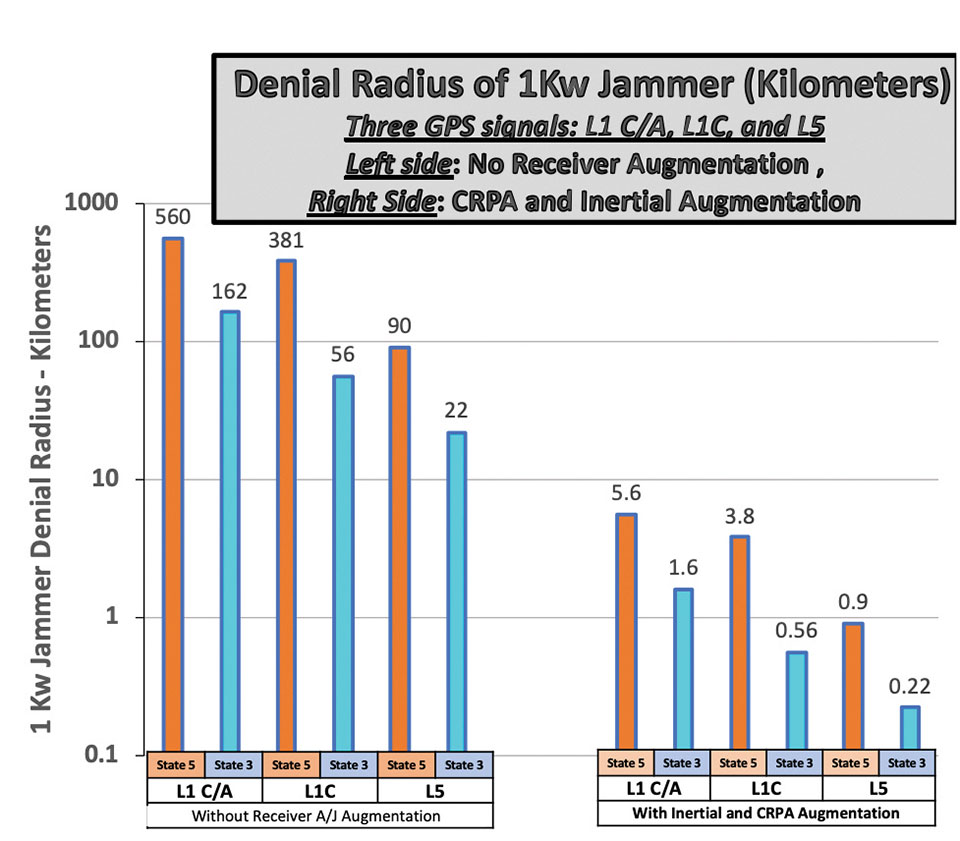
For our basis for comparison, we will consider the L1 C/A signal in full accuracy (State 5) tracking mode and a 1-kW noise jammer.5,6 For this situation, the line-of-sight jammer could deny GPS to a radius of about 560 kilometers. A discussion of the lower accuracy State 3 tracking is included below.
It is useful to consider toughening techniques in four major categories.
Toughening Category 1: Signal Processing. With L1 C/A, GPS receivers can improve jamming resistance, albeit with loss of ranging (tracking) accuracy, by using code tracking mode – State 3. This reduces a line-of-sight jammer’s denial radius (DRRR) to about 0.29 (a 10.7 dB improvement).
Toughening Category 2: Inertial Components and Very Stable User Clocks. This includes miniature micro-electromechanical (MEMS) components up to high-grade inertial measurement units (IMUs) and quartz to chip-scale atomic clocks (CSACs). These techniques enable narrower tracking filters and longer averaging, as well as allowing navigation through regions when GPS is denied. The range of DRRRs is 0.40 down to 0.10. We will use a nominal value of 0.18 (a 15-dB improvement).
Toughening Category 3: CRPAs. Controlled reception pattern antennas (CRPAS) are digital, multi-element, phase-steered antennas. They represent well-understood and available technology; they have been used in large surface-search radar systems for many decades.7 They can be used in null-steering or beam-steering modes.8 The number of antenna elements could range up to dozens. Potentially, they could produce DRRRs down to .01 — that is, a 99% reduction of jammer radius to 1% of the unprotected GPS receiver value.
Unfortunately, the U.S. government does not allow more than three-element CRPAs to be manufactured or sold for civil use. 9 This is due to some very old International Traffic in Arms Regulations (ITAR). For our nominal example, we will assume the restriction has been relaxed and use a CRPA of about 20 elements, which should produce a DRRR of 0.06 (a 25-dB improvement).
Toughening Category 4: Signal Alternatives. This category includes alternative modulations at 1575 MHz (L1C, Galileo or other GNSS) and alternative frequencies (L5, L2, Galileo). Note that the modern signals generally offer significantly improved signal-processing toughening as well as increased power.
Using L1C in State 3 compared to L1 C/A in State 5 would yield a DRRR of 0.10. (a 20.3-dB improvement). The L1C international signal should be operational on GPS by mid-decade. The L5 signal, at 1176 MHz, is clearly the most capable of the civil GPS signals in terms of jam resistance. L5 also should be declared operational by mid-decade. As the use of LEO communication satellites matures, their use may also fit this category.
Summary of Receiver Toughening Options. Quantification of the selected, nominal receiver augmentations are summarized in FIGURE 1 for both full accuracy (State 5, centimeter-level accuracy in RTK) and for less accurate code tracking (State 3, meter-level accuracy). These results are shown with a logarithmic scale to accommodate the wide range of denial radii.
Figure 1. Effect of receiver augmentations on accuracy for both State 5 and State 3. (Image: Brad Parkinson)
The example shows that a 1-kW hostile jammer’s denial radius10 can be reduced by a factor of about 100, using the conservative example augmentations of inertial and CRPAs. Because area is proportional to radius squared, the effective denial area of an augmented receiver would be 1/10,000th of the unaugmented receiver, using the example values.
Reverting to code-only (State 3) tracking, it enables operating through higher levels of jamming, albeit with less ranging precision. All these receiver augmentations and tracking techniques would also offer a significant defense against any attempt to spoof (deceive) the position measurement. Again, none of these techniques are new; we demonstrated the capabilities at the original GPS Joint Program Office in 1978, more than 40 years ago. Today, many competent manufacturers are offering toughened GPS receivers with combinations and variations of these techniques.
GPS jamming tests at White Sands have caused aircraft interference, which could be largely avoided with toughened receivers. Here, M-code is tested on Joint Light Tactical Vehicle platforms in 2020. (Photo: Joe Bullinger/U.S. Navy)
Meeting Increasing Threats
Threats of both jamming and spoofing seem to have accelerated. Devices to perform these illegal acts are freely advertised on the internet. In fact, we read of incidents both in the United States and abroad.11 Near White Sands Missile Range in New Mexico, there have been GPS air traffic control outages due to authorized military operational jamming exercises. Such interruptions could be largely avoided if more robust (toughened) GPS receivers, with the enhanced jam resistance techniques outlined here, were in use.
News reports also highlight the spoofing issue. Hardening against this threat is also a task for toughening. A serious spoofing sequence usually starts with a strong jamming signal to cause the user’s receiver to break lock, followed by a strong false GNSS signal that causes false lock by the receiver. Using the false signal leads to a false position, of course. The first line of defense is to avoid the break-lock threat. Failing this, numerous self-check and authentication schemes can be used to avoid false positions.
A conclusion is that avoiding the break-lock jamming is a first line of defense against a spoofing attack. Of course, the toughening techniques to avoid this are the main subject of this paper. One well-known expert has stated that, for a well-designed receiver, a spoofing attack might deny the measurement of position, but should never cause false PNT. I will leave further discussion of spoofing to other authors.
Returning to disruptions of service in general, some have suggested many interference occurrences have gone unreported, because the typical user would not know where to make such a report. To remind the reader, the official reporting center is online at www.navcen.uscg.gov/?pageName=gpsUserInput.
In addition, the U.S. Federal Communications Commission (FCC) has repurposed a portion of the spectrum adjacent to the main GNSS L1 frequency (1575 MHz). The agency is converting the license holder’s original authorization to transmit a weak space-transmitted signal into a much stronger terrestrial system, potentially with thousands of transmitters. Extensive testing of civil GPS receivers by the U.S. Department of Transportation demonstrated that the planned repurposing will interfere with many existing receivers. Some observers call this disruption “legal jamming.”
Such a new spectrum use could have grave impacts on those existing receivers, notably aviation (especially helicopters and UAVs) and first providers. On the other hand, installing toughened replacement receivers would make the users virtually immune to this threat.
So, this begs the question: If the receiver toughening techniques are so effective, why are they not more prevalent?
Barriers to Adoption
Let’s examine the potential resistance to more extensive use of receiver augmentations.
Knowledge. This involves underestimating the threat to PNT and not understanding that toughening techniques are available. As mentioned above, threats to the fragile GNSS signals are growing.
There seems to be little interest in the U.S. government to monitor and suppress interference in the United States. Internationally, the reported incidents continue to increase.12 It is also reported that certain European aircraft manufacturers have installed advanced, deeply integrated inertial systems with civil GNSS receivers to defeat or “flywheel” through radio-frequency threats (particularly in the Middle East).
As this threat trend continues, GPS manufacturers and users must realize that many of these solutions will take time to authorize, implement and install. It appears that the media are not aware that not only are the toughening techniques outlined here feasible, but many manufacturers have product offerings that address these threats. Having off-the-shelf solutions will give the PNT user the opportunity to retrofit and defeat such threats.
Cost. The cost for a receiver to revert from State 5 to State 3 is zero, and all receivers that use Code 5 (for example, RTK) would naturally have this built in. Regarding use of other frequencies (such as L5) and modulations (L1C) rather than the original L1 C/A, there is some small cost associated, including the additional antenna for L5. Note that all modern cellphone chips, such as Qualcomm’s, have this capability — including integrated carrier-phase measurements — in a chip that is estimated to cost about $5. A potential barrier is that the L5 and L1C signals are not yet declared operational, but these newer GPS signals should be operational within about five years.
The costs of many inertial components (accelerometers and gyros) have plummeted in the last few decades with the proliferation of MEMS devices, particularly into cellphones and automobiles. Their power consumption has also decreased while their performance has steadily improved. Full IMUs are much more expensive, but are already installed on many commercial aircraft. Robust toughening with inertial sensors can be achieved, but requires deep integration and careful engineering.
Depending on their complexity, CRPA antennas can be a costly receiver augmentation. Very high-speed (330 MHz is available), 16-bit, A-to-D converters are at the heart of most of these phased-array devices. Some are priced at about $150 each. Applications with a high premium for PNT availability in the face of interference — such as commercial aircraft and cargo ships — should find them affordable. Aircraft manufacturers have resisted retrofitting existing aircraft with larger diameter CRPA antennas because of costs. For some of these applications, integration costs can be more than the costs of the receiver itself, particularly if not included in the original manufacture.
As the yearly sales of fully toughened receivers increase, the economies of scale should significantly reduce unit costs. Each application will make its own determination of affordability, based on risk.
Government restrictions. Civil use of CRPAs with four or more elements is restricted by ITAR. These are well-meaning restrictions on technologies that could be used against the United States by hostile military forces. Unfortunately, the phased-array antenna techniques are not only well understood and tested, but relatively inexpensive components are widely available on the open world market. In particular, the restriction on the number of CRPA elements for civil use should be completely removed. All potential enemies are well aware of the beam-steering method and have ready access to the parts to build them. Thus, the restriction is only harming civil users without affording any apparent improvement in general military posture.
Certified aviation receivers need approval for deep integration of inertial systems and multi-element CRPAs. (Photo: JasonDoiy/iStock/Getty Images Plus/Getty Images)
Gaining permission: FAA flight certifications. To be used in commercial aircraft operations, navigation equipment must be certified by the U.S. Federal Aviation Administration (FAA). Current, certified GPS aviation receivers have rudimentary toughening techniques, but gaining approval for deep integration of inertial systems and multi-element CRPAs must be completed. It is gratifying to hear that work is underway to do this.
Any civil solution for the United States must expand integrity monitoring beyond GPS to include all GNSS, and must be operationally included in the FAA’s integrity monitoring with WAAS.
Recommendation
In describing resistance to interference, I have introduced the idea of DRRR – Denial Radius Reduction Ratio. Also, I have used a 1-kW white-noise jammer as a standard threat for calculating the denial radius of various GPS receiver configurations. My recommendation is that equipment manufacturers specify their receiver offerings by stating their equipment’s denial radius against a “standardized” 1-kW EIRP white-noise jammer.
Summary
Media reports of interference to GPS may be accurate, but they generally do not recognize that available toughening techniques can largely defeat those interference threats. While exploring systems-level replacements or augmentations (such as LEO ranging or Loran) is worthwhile, GPS (or GNSS) still offers the greatest capability in combined terms of accuracy, integrity and coverage.
The goal of all PNT providers — GPS operators, certifiers and manufacturers — should be assured PNT, with the expected accuracy and availability. The described toughening techniques to do that have been known for decades, but have not been generally adopted by many critical civil users. Many manufacturers do offer civil products under existing government constraints.
The purpose of this article was to describe and advocate the solutions available to increase the robustness and toughening of civil GPS receivers. For example, readily available toughening augmentations for civil receivers can reduce the denial radius of interference by 99% or more. This implies that any denied area would be squeezed down to 1/10,000th of that experienced by an unaugmented receiver.
The payoff is high, and should be affordable to many high-end, safety-of-life users. Therefore, a renewed focus on toughening of GPS receivers is overdue. We discussed barriers to rapid adoption but, more than the specifics, it is crucial to fully and urgently embrace the goal of toughening receivers, particularly removing the ITAR restriction on antennas.
Opinions expressed in this article are those of the writer and should not be construed as the official position of the PNTAB or any U.S. government organization.
Notes
1. While not a part of the U.S. Department of Defense’s GPS operation, the FAA’s integrity signal (WAAS) is a GPS-type signal directly available and being used by almost all modern GPS receivers, including cellphones.
2. This is the ration of Denial Radius between, for example, unaugmented L1 C/A in State 5 and augmented L1C in State 3. Please see later footnote and graph.
3. Calculated as 10 (–15/20)
4. Of course, the more traditional dB measure of jammer resistance can (in most cases) be simply summed to estimate the total effectiveness. The use of DRRR gives a more intuitive calibration, particularly for non-technical persons who may not be at all familiar with dBs.
5. State 5 is the tracking mode that provides full accuracy; it requires tracking both the PRN code and the reconstructed carrier. It is required for RTK positioning, which is usually used for automatic control of machines or vehicles. It is most vulnerable to interference. Less vulnerable is State 3 tracking, which only provides code tracking, with precisions of perhaps a few meters.
6. Deliberate jamming using “matched spectrum” GPS-like modulations have also been employed in the Middle East. The toughening techniques described are also generally applicable, with appropriate rescaling. The matched spectrum is fundamentally used to improve the jammer spectrum efficiency.
7. See Michael Jones, “Anti-jam systems: Which one works for you?”, posted on gpsworld.com on June 14, 2017, for a survey of manufacturer offerings at that time. Named companies generally continue to offer improved, jam-resistant products.
8. Phased-array antennas, by their nature, distort phase and would probably have to be calibrated for precise operations such as RTK. Fortunately, we understand that this problem has been reportedly addressed and largely solved by the U.S. Navy’s JPALs program.
10. The denial radius results shown can be easily scaled for weaker or more powerful jammers. The scaling goes as simply the square root of the power ratio of a different size jammer to the 1-kW example. A 10-watt jammer is 1/100th the power of the example. The denial radius would then be one tenth of the example, which is the square root of 1/100.
11. “Ships have reported an increasing number of cases of significant GPS interference and jamming in recent months. The geographic areas with more than one reported incident include the eastern and central Mediterranean Sea, the Persian Gulf, and multiple Chinese ports.” (Source: www.gard.no/web/updates/content/30454065/gps-interference-and-jamming-on-the-increase).
“North Korea is using radio waves to jam GPS navigation systems near the border regions, South Korean officials said. The broadcasts have reportedly affected 110 planes and ships and can cause mobile phones to malfunction.” (Source: www.bbc.com/news/world-asia-35940542).
12. “Reports of GPS outages submitted by pilots from the cockpits of commercial flights show that disruptions to the navigation system, which was created and is maintained by the U.S. government, are now standard occurrence on the flight routes between North America and Europe and the Middle East, according to data from the European Organization for the Safety of Air Navigation, known as Eurocontrol.” Fortune Magazine, Nov. 1, 2020.
Innovation is the watchword in Washington this year. Amidst an ongoing supply-chain crisis and rising global trade tensions, policymakers have put renewed emphasis on U.S. leadership in such industries as semiconductors, wireless broadband and artificial intelligence — areas rightly seen as the “enabling technologies” of the 21st century.
Alongside chips and supercomputers is another innovation underpinning everything from our communications networks to financial transactions and air transportation: GPS technology. 2022 will see a flurry of activity to accelerate U.S. competitiveness for the modern economy and accelerating the modernization of our GPS constellation must place high on this list.
It’s no surprise that allies and adversaries alike have taken notice of GPS. While for decades U.S.-led GPS was the “only game in town” for global navigation satellite systems (GNSS) services, the current global picture is much changed. Russia, China, the European Union, Japan, India and other nations have explored, tested and deployed satellites to build out their own global or regional positioning, navigation and timing (PNT) networks and capabilities. The more recently deployed GNSS — including China’s BeiDou, which was completed in 2020 — represent a competitive threat by our international adversaries in spite of U.S. GPS technology advancements in performance and resilience. The potential loss of global leadership poses a dramatic challenge for U.S. interests.
Although our current GPS constellation continues to enable critical services that touch nearly every aspect of daily life, the oldest satellites were launched in the late 1990s. As new, more advanced GPS satellites go up in the sky, we can take several policy steps here on the ground to ensure that GPS remains the global standard — undermining attempts to create an information ecosystem independent of the United States and reliant on our international competitors.
Enter the United States’ GPS modernization program. Allocating the resources necessary to accelerate the launch of new GPS satellites will pave the way to keeping GPS globally competitive — both in defense and civil applications. Take accuracy, for starters. New GPS satellites will bring three times better accuracy than existing systems and up to eight times improved anti-jamming capabilities, both of which will keep us competitive and add critical security against domestic spoofers and foreign adversaries.
While U.S. firms should continue to create multi-constellation receivers that are interoperable with global PNT signals, U.S. policy should promote American technological leadership by accelerating modernization of the GPS space and control segments. Importantly, a necessary element of this technological leadership is development of a systematic roadmap to spur adoption of these new modernized features in civil applications. Establishing this clear pathway for civilian applications of a modernized GPS constellation is critical to ensuring that the potentially more than $1 billion of economic benefits added every day by the U.S. civil GPS sector are fully realized.
As Congress continues to focus on innovation and global competition, the GPS Innovation Alliance is committed to working with policymakers to promote the critical security, economic and diplomatic benefits to the United States of investing in next-generation GPS infrastructure.
Originally a product of the Sputnik era, GPS has demonstrated the very best features of competitive U.S. government investment. As the United States prepares for a renewed era of global competition, the promise today of invigorated support for GPS remains the same.
The United States must continue to lead by modernizing GPS and establishing a clear pathway for civilian applications of the improved constellation. (Image: matejmo/iStock/Getty Images Plus/Getty Images)
YellowScan will host its fourth conference for drone users June 13-14, 2022, at Domaine de Verchant, Montpellier, in the south of France. Attendees at Lidar for Drone 2022 will be able to meet and link up with YellowScan customers, partners and distributors.
Attendees will gain insight into the lidar industry and hear from interesting and innovative lidar users, thanks to an extensive program of technical sessions, workshops, live demonstrations and training.
There will also be networking opportunities — the user conference is a great chance for attendees to showcase their involvement in the lidar market.
This year’s conference will include a celebration of YellowScan’s 10th anniversary.