Topcon Positioning Group has announced its MC-Max machine control solution. Based on its MC-X machine control platform, and backed by Sitelink3D — the company’s real-time, cloud-based data management ecosystem — MC-Max is a scalable solution for mixed-fleet heavy equipment environments. It is designed to adapt to owners’ machine control and data integration needs as their fleets and workflows expand.
MC-Max increases processing power, speed, accuracy, versatility and reliability, Topcon said. It can be installed on a full range of dozers and excavators, using the same basic modular components. Modern, redesigned user and product interfaces were developed based on real-world applications and customer feedback and provide a simplified and immersive user experience that allows operators to easily learn the system.
Photo: Topcon
“With MC-Max, we’ve created a solution that is flexible and can continue to grow as a contractor’s needs and capabilities expand,” said Jamie Williamson, executive vice president, Topcon Positioning Group. “This new solution provides improved scalability and precision in the field and offers business owners real-time data integration, connectivity and resource management capabilities across their entire workflow.”
The MC-Max solution offers flexible mounting solutions, as well as optional automatic blade and bucket control for a variety of machines. The system also provides a full battery of positioning technologies ranging from slope control to laser, multi-constellation GNSS, robotic total station and millimeter GPS systems.
MC-Max provides project managers a real-time view of machine positions, activities and onsite progress, and is compatible with a wide range of site communications systems.
Topcon MC-X Platform. The Topcon MC-X Platform is designed to make machine control easy to use and affordable for contractors. The platform ties together mixed fleets by interacting with multiple versions of 3D-MC, providing connectivity to Sitelink3D and taking advantage of the multi-constellation capabilities of GNSS antennas.
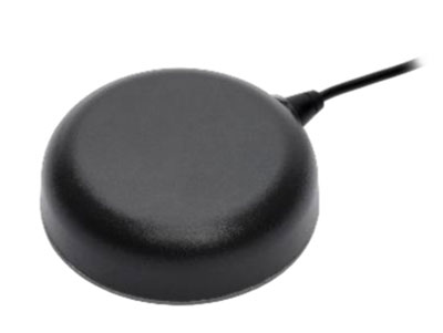
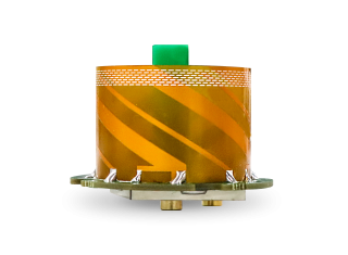
Tallysman Wireless Inc. has added the TW7976 to its surface mount line of antennas. The TW7976 covers GPS/QZSS-L1/L2, QZSS-L6, GLONASS-G1/G2, Galileo-E1/E6, and BeiDou-B1/B3, as well as L-band correction signals.
The addition of L6 and E6 coverage supports the Galileo High Accuracy Service (HAS) and the QZSS Centimeter Level Augmentation Service (CLAS) correction signals. Regional augmentation services such as WAAS (North America), EGNOS (Europe), MSAS (Japan), GAGAN (India) and high-precision L-band correction services are also supported.
The TW7976 features a patented Tallysman Accutenna, which provides multi-constellation and multi-frequency support. Accutenna technology offers an excellent axial ratio that mitigates multipath signals and produces clean code and phase measurements. Accutenna antennas enable high-precision techniques, such as real-time kinematic (RTK) and precise point positioning (PPP), which provide accurate and precise position estimates (< 0.1 m).
Another key feature of the TW7976 is a deep pre-filter that attenuates out-of-band signals. This is crucial in challenging urban environments where near-band and inter-modulated signal interference from LTE and other cellular bands is common.
The surface-mounted TW7976 weighs 180 grams, is IP67-rated, and supports direct screw, magnet or adhesive-tape attachment. The TW7976 is ideal for many applications, including autonomous vehicle navigation (land, rail, sea, and air) and high-precision automotive and agricultural positioning.
Inertial Labs has acquired Memsense, a developer of inertial measurement units (IMUs) and a long-time business partner. Inertial Labs is a developer and supplier of orientation, inertial navigation and optically enhanced sensor modules.
The Inertial Labs and Memsense workforce will address the rapidly evolving needs of global customers. The combined company of more than 100 employees and 500 customers expects to introduce breakthrough technologies at an accelerated pace across high-value areas such as autonomous vehicles, GPS-denied navigation, industrial machines, and aerospace and defense.
In addition, Inertial Labs and Memsense have a strong balance sheet to support critical business initiatives, deliver with short product lead times, and invest in promising integrations, the company stated in a press release.
“Our strategic acquisition of Memsense brings together two high growth companies with proven performance in solving some of the world’s most difficult stabilization and navigation problems,” said Jamie Marraccini, president and CEO of Inertial Labs. “Our customers will benefit from our combined capabilities and resources.”
“As we move forward, Inertial Labs and Memsense will define the future of MEMS IMUs,” said James Brunch, CEO of Memsense. “Our focus on innovation, our world-class team, and our strength in customer collaboration allow us to deliver the exact specs needed by our customers.”
Inertial Labs cites the following benefits for current and future customers:
increased production capabilities of up to 50,000 units annually to meet the needs of larger aerospace and defense contracts for guidance and navigation applications
low-cost, consumer-grade IMUs, ruggedized industrial-grade models, affordable tactical-grade IMUs, and IMUs with near-FOG level of performance (0.1 deg/h bias instability)
a larger range of devices for unmanned ground vehicles (UGV); unmanned aerial vehicles (UAV); autonomous and automated ground vehicles (AGV).
expanded research and development efforts to accelerate delivery of IMUs for stabilization applications, such as electro-optical systems, pan-and-tilt platforms, and remote weapon stations (RWS)
new IMU models with improved performance will increase capabilities of the company’s GPS-aided inertial navigation systems (INS), wave sensors, motion reference units (MRU) and attitude heading reference systems (AHRS)
development of new high-performance systems including a MEMS-based gyro-compasses (3 MILS azimuth and 1 MIL elevation accuracy).
Unicore is a manufacturer of GNSS hardware and a sister-company to Rx Networks within the BDStar group of companies, which is headquartered in Beijing, China.
Unicore GNSS receivers have been deployed in a wide variety of applications, including reference stations, surveying, mapping, precision agriculture, machine control, drones and robotics, vehicle navigation, timing, internet of things (IoT) and more.
Rx Networks is a supplier of high-accuracy services and assistance data to a growing list of GNSS hardware manufacturers. As high-precision GNSS becomes ubiquitous, those seeking precise positioning solutions can now make use of Unicore GNSS hardware made even more accurate with Rx Networks data services.
“Unicore GNSS hardware has shown to have outstanding positioning performance,” said Cameron Baird, head of Business Development, Hardware Sales. “I am excited to see the democratization of inexpensive high-precision GNSS hardware with Rx Networks’ TruePoint.io PPP-RTK correction services.”
On Nov. 9, the National Geodetic Survey (NGS) announced the release of a new Beta NGS Map. This web application allows users to view multiple datasets that are useful to anyone planning or performing a survey project, or anyone that’s just looking for NGS marks.
The map enables users to access NGS datasheets, OPUS Shared Solutions, and the NOAA CORS Network. It also provides a measuring tool, multiple basemaps, and the ability to export data.
I recently used this tool on my iPhone to locate marks when I was traveling. It’s an amazing tool that is easy to navigate, and a useful tool for identifying marks to be included in a project.
The NGS homepage provides a link to the Beta NGS Map (see below).
Image: NGS Website
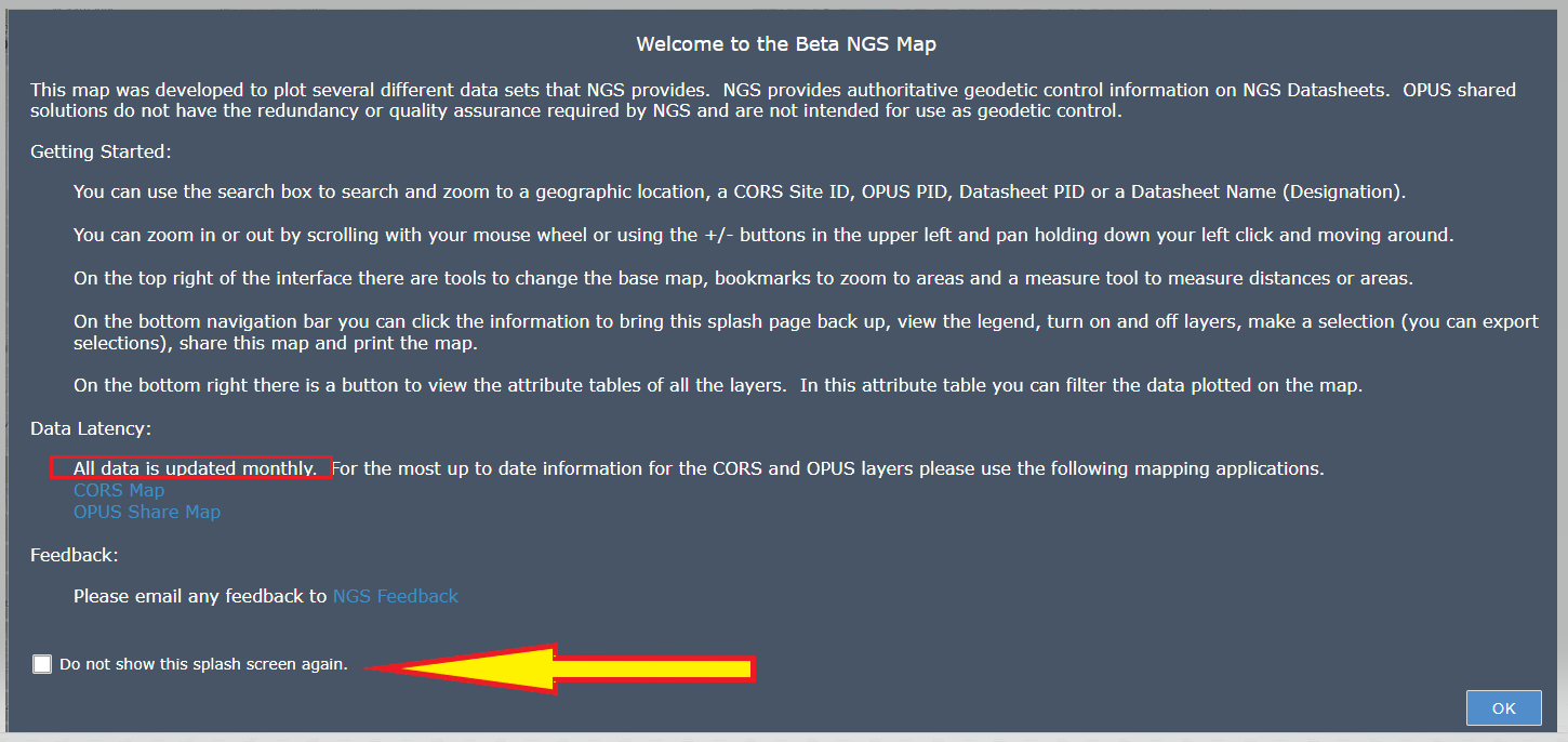
When you first click on the NGS Map link a short narrative appears that provides a brief set of instructions on how to use the map (see below). There’s a box that you can check so that the narrative will not appear every time you access the site. It’s important to note that the data for the CORS and OPUS Shared results are updated monthly. This could be an issue in some instances, therefore users should always check the NGS website for the latest information for the NOAA CORS Network or OPUS Shared map.
Beta NGS Map. (Image: NGS website)
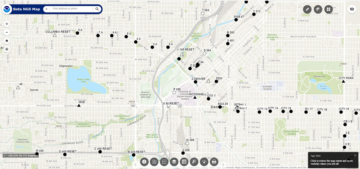
After you click OK at the bottom right of the page, a sample map will appear.
Sample map of Denver region. (Image: NGS website)
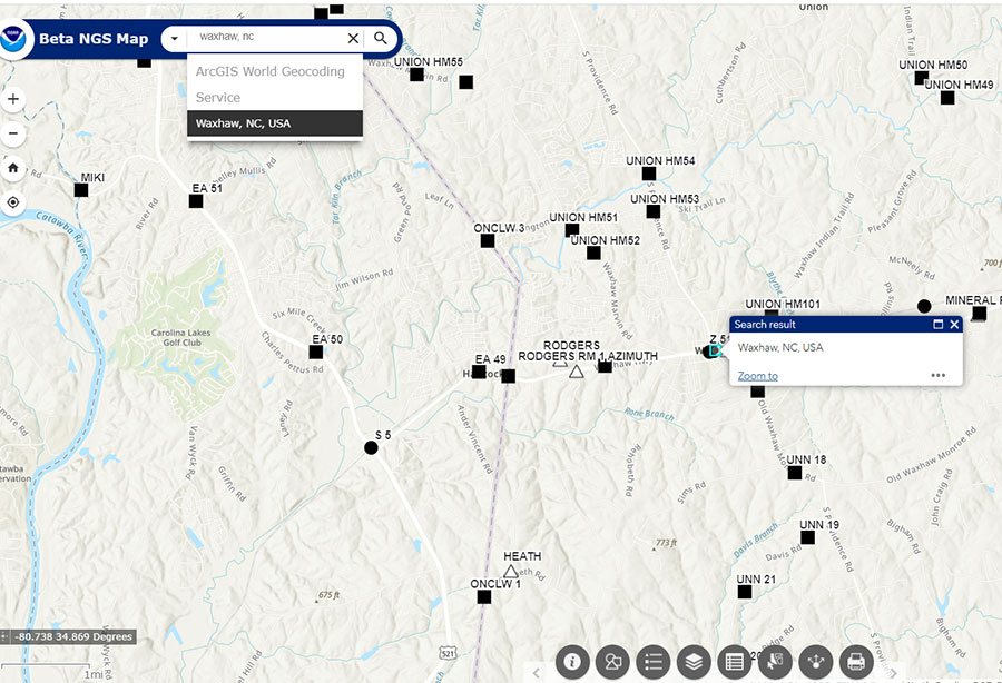
The map allows the user to type in a location (geographic location, CORS Site ID, OPUS PID, Datasheet PID or Datasheet Name) to start a search. See the “Waxhaw, North Carolina, Region” map as an example of entering a geographic location.
Waxhaw, North Carolina, Region. (Image: NGS Website)
The bottom navigation bar has eight buttons.
List of buttons at the bottom of the map. (Image: Dave Zilkoski)
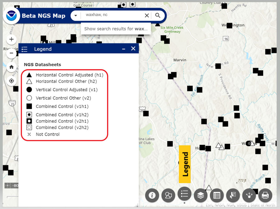
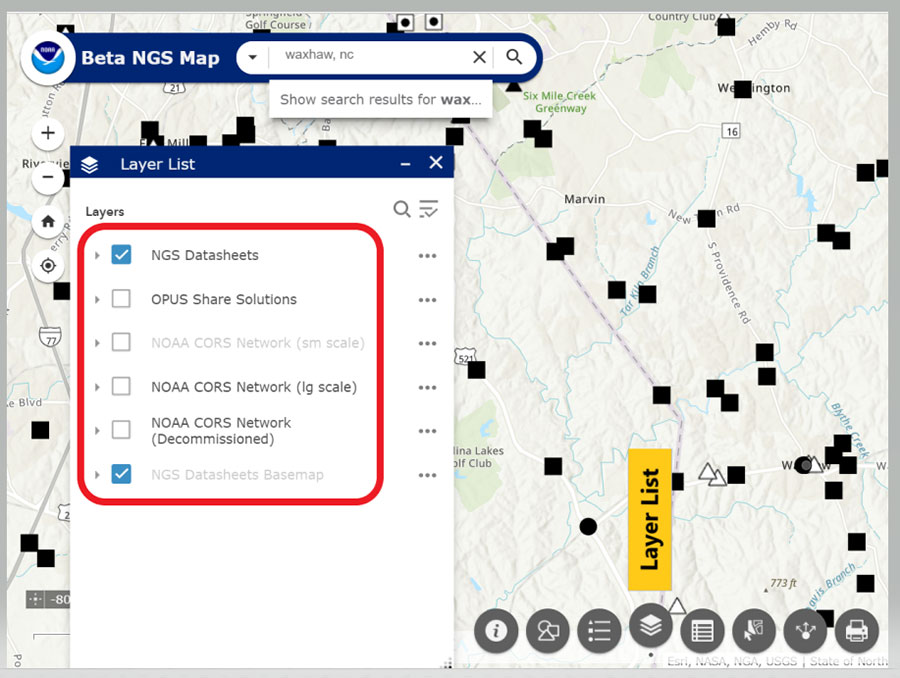
When clicked, a window pops up providing information about that particular button. (For example, see “Map with Legend Information” below.) The legend will include all layers that have been selected. In my example, the datasheet layer was the only layer I had selected (see “Map with Layer Information”.)
Map with legend information. (Image: NGS Website highlighted by Dave Zilkoski)Map with layer information. (Image: NGS website highlighted by Dave Zilkoski)
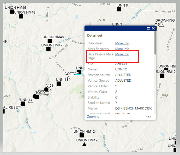
When the user clicks on a symbol, a box will appear with information about the mark. See “Information for Station UNN 12” below.
Information for Station UNN 12. (Image: NGS Website)
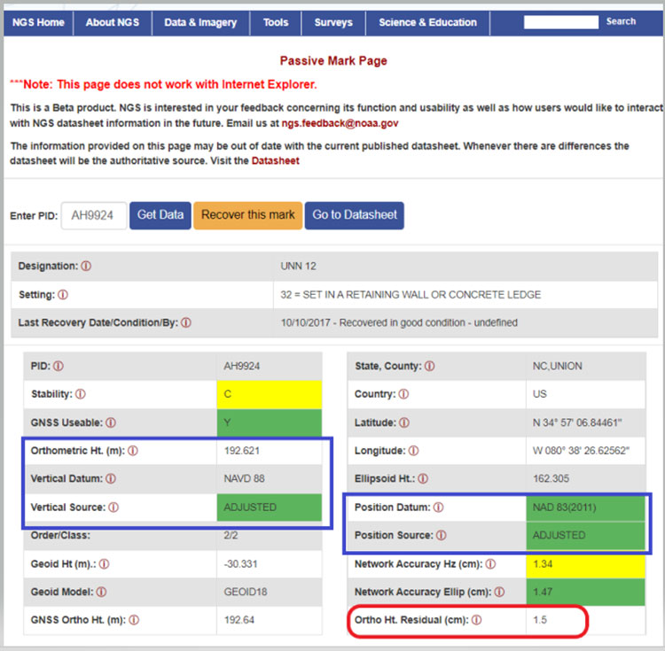
The box contains information from the NGS datasheet as well as a link to the actual NGS database. A nice feature of this webtool is that it provides a link to NGS’s Beta Passive Mark webtool. My October 2020 Survey Scene column highlighted the features of the NGS’s Passive Mark tool. The box captioned “Passive Mark Page for Station UNN 12” is an example of the tool. I’ve highlighted several items important to individuals planning surveys, such as the mark’s coordinates, datums and source, and the Orthometric Height residual (the difference between the estimated geoid height and the modeled hybrid geoid height).
Passive Mark Page for Station UNN 12. (Image: NGS website)
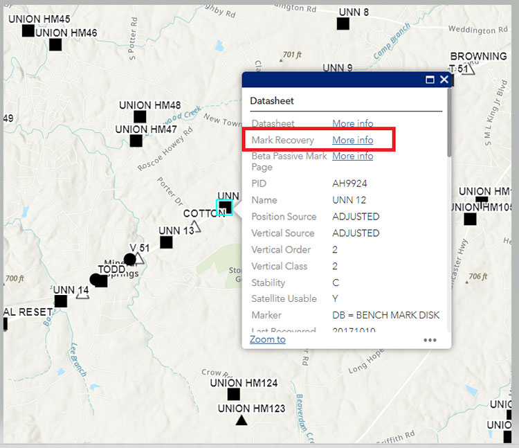
Another great feature is that the user can click on the Mark Recovery link to provide the latest recovery information for a mark (see the box titled “Mark Recovery Link for Station UNN 12 “).
Mark Recovery Link for Station UNN 12. (Image: NGS website)
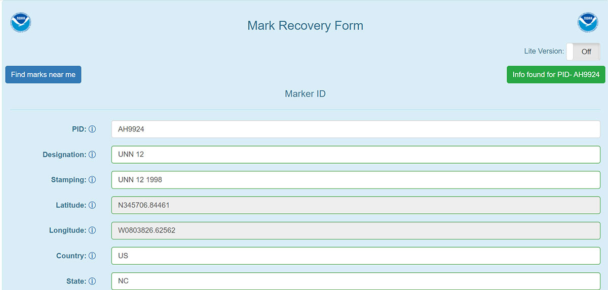
When a user clicks on the More info link for the Recovery Mark option, a Mark Recovery Form is provided for the user to enter the recovery information for the mark. The routine fills in the fields based on the current data in NGS’s database (see the box titled “Mark Recovery Form for Station UNN 12”). The user can enter changes or new information about the mark. This information is very important to users planning surveys. Just because a mark has been occupied by GNSS in the past doesn’t mean that it’s still a good station for occupation by GNSS. The environmental conditions around the mark could have changed since the last time it was occupied; for example, new buildings and/or growth of trees may now obstruct the GNSS signals.
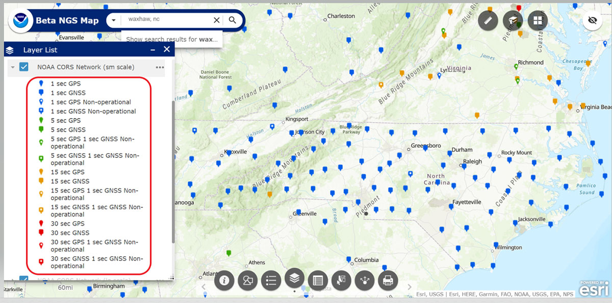
As previously stated, the NOAA CORS Network is one of the layers available. The box titled “Map of NOAA CORS Network in the North Carolina Region” depicts the locations of the NOAA CORS in North Carolina. The layer list provides some of the attributes of the CORS, such as the sampling rate and which GNSS signal are collected at the site.
Map of NOAA CORS Network in the North Carolina Region. (Image: NGS website)
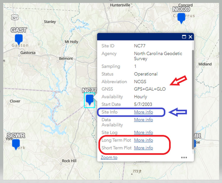
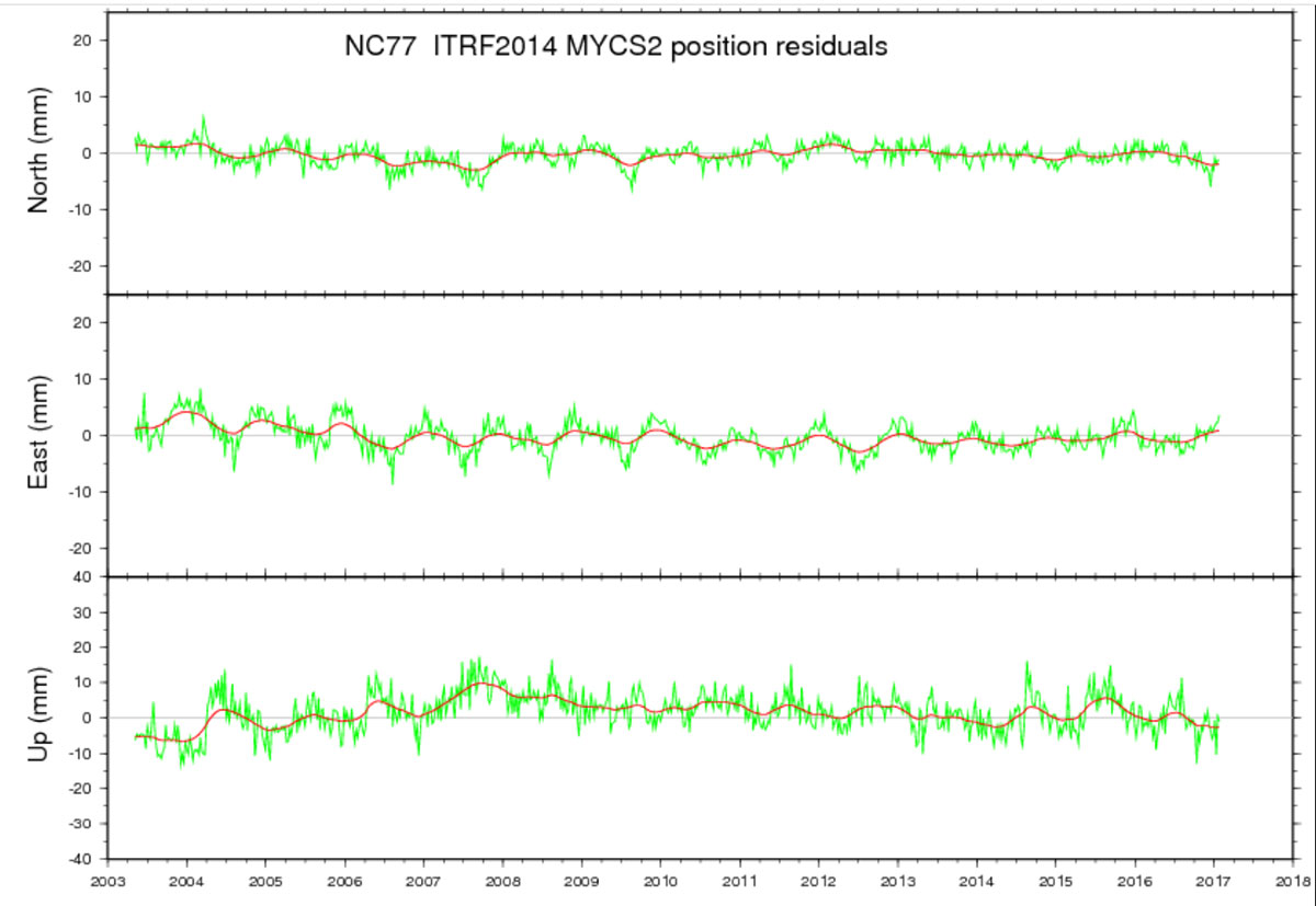
When a user clicks on a specific CORS, a box appears with information for that particular CORS. I’ve highlighted several items in the box titled “Information on CORS Site ID NC77.” In my example, CORS NC77 collects GPS, Galileo,and GLONASS data. Also, users can obtain long-term and short-term plots of the CORS.
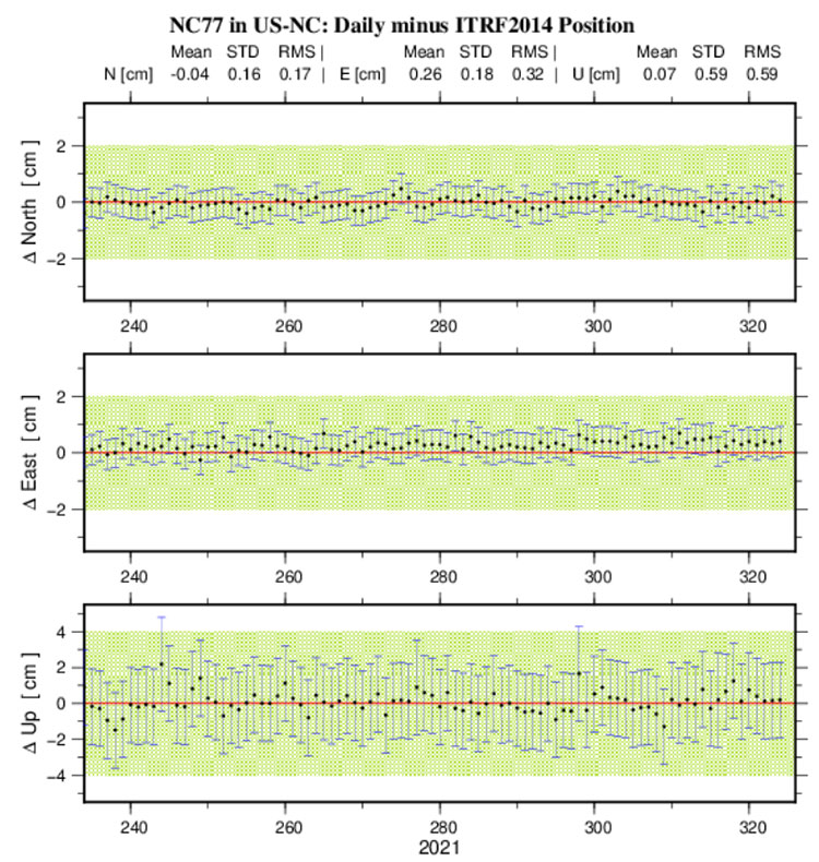
Once again, this feature is important to users planning and performing GNSS survey projects. As in the other features, clicking on the More Info link will bring up the plots. The plots for CORS NC77 are provided in the boxes titled “Long-Term Plot Information on CORS Site ID NC77” and “Short-Term Plot Information on CORS Site ID NC77” below.
Information on CORS Site ID NC77. (Image: NGS website)Long-Term Plot Information on CORS Site ID NC77. (Image: NGS website)
In the short-term plot, the red line is the published position, and the green hashed area is the tolerance of the NGS position, that is +/- 2 cm horizontal and +/–4 cm vertical. All the error bars are 1 sigma values. This information is useful when selecting NOAA CORS to be included in a survey project.
The short-term plot contains the mean, standard deviation and RMS values for the north, east and up components of the site. When planning a GNSS project, users typically identify several NOAA CORS to be included in the project. However, not all CORS are equal.
I evaluate CORS using the following criteria:
Designated as “operational”
Computed (i.e., measured) velocities rather than modeled (i.e., predicted) velocities.
“Consistent” data depicted in short-term time-series plots.
Network accuracies ~1 to 1.5 cm horizontally and less than ~2 to 3 cm in ellipsoid height.
Clicking on the More Info button for Site Info of NC77 provides a webpage where most of this information can be obtained.
Before conducting any post-processing, the analyst should ensure that all CORS included in the project have data for all of the occupations and that the station’s short-term plots indicate stability.
Short-Term Plot Information on CORS Site ID NC77. (Image: NGS website)
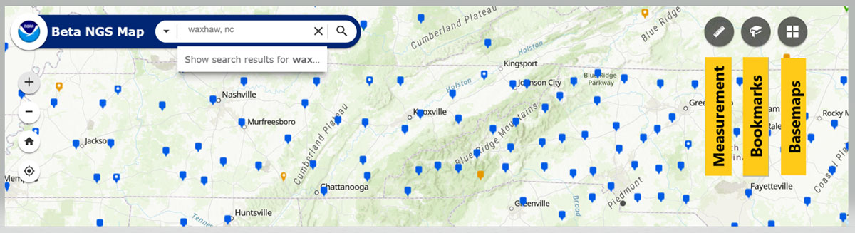
Tool buttons are situated in the top right section of the map. Included are a measurement tool to measure distances between marks and areas, a bookmarks tool to zoom to areas, and a basemaps tool to change the basemap. See the box titled “Useful Tools.”
Useful tools. (Image: NGS website)
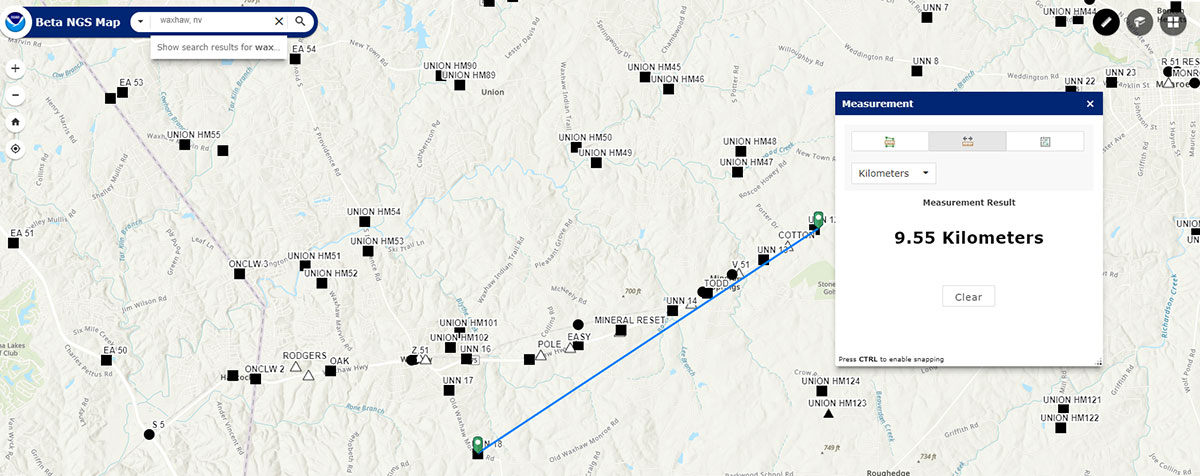
Some users may find the measurement tool helpful when planning a survey. The box titled “Using the Measurement Tool” is an example of measuring the distance between two stations.
Using the measurement tool. (Image: NGS website)
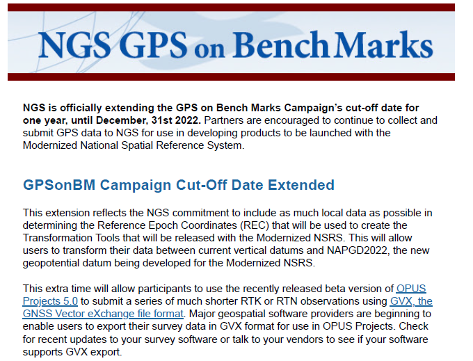
The last item that I’d like to highlight is that on Nov. 18, NGS has officially extended the GPS on Bench Marks campaign’s cut-off date for one year until December 31, 2022. See the box titled “NGS GPS on Bench Marks Notice.”
NGS GPS on Bench Marks Notice. (Image: NGS website)
NGS is anticipating that this extra time will allow users to provide additional GPS on Bench Marks data using the recently released beta version of OPUS Projects 5.0.
As stated in the NGS news release, this extension reflects NGS’ commitment to include as much data as possible in determining the Reference Epoch Coordinates (REC) that will be used to create the Transformation Tools to be released with the Modernized NSRS.
I encourage everyone to try the new Beta NGS Map. As in all of NGS beta products, NGS would like users to try the tools and provide feedback on what they liked and what they didn’t like. They are trying to develop tools useful to everyone, but that won’t be possible unless they hear from users.
GNSS correction service receivers and the firmware-upgraded ZED-F9P upgraded to achieve reliable centimeter-level accuracies in seconds
Photo: U-blox
U‑blox is offering a suite of products and feature additions that simplify access to reliable centimeter-level positioning accuracies for the industrial, navigation and robotics markets.
The upgraded ZED-F9P high-precision GNSS receiver module and the corresponding NEO-D9S and NEO-D9C GNSS correction data receivers offer customers flexibility in assembling scalable solutions for their specific use cases, including robotic lawnmowers, unmanned autonomous vehicles (UAV) and semi-automated or fully automated machinery.
The software-upgraded u‑blox ZED-F9P-04B high-precision GNSS receiver is the first to support a secure SPARTN GNSS correction data format. It seamlessly connects to two new GNSS correction service receiver modules that stream correction data from communication satellites:
The u‑blox NEO-D9S will initially cover the European and U.S. markets before rolling out to the other areas of the globe.
The u‑blox NEO-D9C will cover Japan.
The NEO-D9S receives correction data using the SSR SPARTN data format over the satellite L-band channel. It uses cryptography to securely deliver PPP-RTK GNSS correction data, such as that offered by u‑blox’s PointPerfect service.
The NEO-D9C leverages the subscription-free Centimeter-Level Augmentation Service (CLAS) broadcast over mainland Japan provided by the Japanese Quasi-Zenith Satellite System (QZSS) constellation on the L6-band channel.
While u‑blox GNSS receivers are designed to work with most correction services on the market, pairing the ZED-F9P with the NEO-D9C or the NEO-D9S correction data receiver enables customers to save data transmission cost and operational efforts, the company said.
ZED-F9P-04B offers a new feature called protection level, which increases the trust applications can place in its position output. By continuously outputting the upper bound of the maximum likely positioning error, referred to as the protection level, the receiver lets autonomous applications, such as UAVs, make efficient real time path planning, increasing the quality of their operations.
In the case of robotic lawnmowers, the increased accuracy and reliability of the position will, for example, make it possible to do away with boundary wires, which today are buried under the turf to delimit the mowing area. Furthermore, it will allow lawnmowers to systematically cover a plot based on a digital map, as opposed to the random mowing approach commonly used today.
First samples of these products are available today, in professional and automotive grade. The correction data receivers will be available in automotive grade for the automotive markets.
Harxon has introduced the HX-CUX005A to its family of helix antennas.
The HX-CUX005A is an embedded helix antenna designed for high-precision positioning. It offers superior satellite signal tracking, including GPS, GLONASS, Galileo and BeiDou as well as L-band correction service.
Upgraded with Wi-Fi and Bluetooth tunable (BT) for better integration, the HX-CUX005A is designed to be an all-in-one solution for surveying, unmanned aerial vehicles (UAVs), personnel and vehicle monitoring, and many more applications.
The powerful antenna has Harxon’s patented D-QHA technology and multi-point feeding technology. It is able to provide reliable and consistent signal tracking with centimeter-level accuracy by exhibiting a stable phase center, 2.5-dBi high gain with ultra-low signal loss, wide beam width and exceptional low-elevation satellite tracking.
In addition, the HX-CUX005A is optimized in circuit layout and equipped with robust pre-filtered low noise amplifier that guarantees excellent out-of-band rejection performance and strong multipath reduction capacity. In this way, unwanted electromagnetic interference is restrained for improved signal filtering over all GNSS frequency bands.
The integration of Wi-Fi and Bluetooth (2.4 GHz/5.8 GHz) provides 1-dBi gain (typical value) to enable easy connection and configuration for mobile device users. Its highly integrated design simplifies development process and reduces costs for device engineers, Harxon said.
Key Features of the HX-CUX005A
Comprehensive GNSS support: GPS, GLONASS, Galileo, BeiDou and L-band correction service
Centimeter phase-center repeatability, high gain at low elevation
Improved signal filtering and excellent multipath rejection
Weighs 10 grams in small form factor to facilitate integration
Integrated with Wi-Fi and Bluetooth tunable (2.4 GHz/5.8 GHz).
Spectranetix Inc., a Pacific Defense company, has announced the SX-124 ruggedized 3U OpenVPX high-performance positioning, navigation and timing (PNT) card.
With an ability to provide timing and positioning information in a GPS-denied environment through sensor fusion, the SX‑124 switch is designed for highly integrated systems with a requirement for the U.S. Army’s C5ISR Modular Open Suite of Standards (CMOSS) and alignment with the Open Group Sensor Open Systems Architecture (SOSA) technical standard.
The SX-124 can accept external sources or use its onboard GNSS receivers as reference inputs for timing and positioning data. The positioning data can be fused with internal and external inertial measurement units (IMUs). It distributes 11 100-MHz outputs and 11 1PPS outputs in a phase coherent manner.
The SX-124 provides timing and position holdover from an internal chip-scale atomic clock (CSAC) and IMU. A built-in time-of-day clock provides accurate network time stamps on system startup without GPS availability.
The SX-124 also provides enhanced location information and can be connected to an external IMU as well as a controlled reception pattern antenna (CPRA).
The SX-124 supports the standard VICTORY shared PNT services from a built-in GNSS timing receiver with an optional built-in M-code GB-GRAM receiver, CSAC and barometer to provide altitude information.
With the option for expansion to support over-the-air rekeying (OTAR), external fiber-optic gyroscope (FOG), alternative navigation (ALTNAV), and additional GNSS systems such as Galileo, the SX-124 supports the defense community’s need for a high-performance assured PNT (A-PNT) solution in the 3U VPX form factor and aligned to the latest open set of standards.
“Reliable situational awareness and cooperative, networked maneuvers demand assured PNT capability,” said Daniel Kilfoyle, CTO of Pacific Defense. “Our A-PNT solution embraces the pntOS open sensor-fusion framework and supports multiple sensor connections including GNSS receiver, GB-GRAM, IMU, FOG, CRPA and a two-channel software-defined RF receiver for added flexibility. Combined with exquisite timing and frequency performance and CMOSS alignment, this PNT card is yet another example of our commitment to CMOSS and SOSA.”
The SX-124 card is on track for production release early next year.
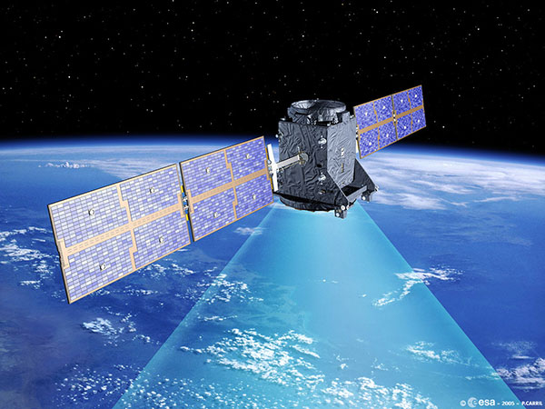
Artist’s rendering of GIOVE-A in orbit. (Image: ESA)
News from the European Space Agency
Europe’s first prototype satellite for Galileo, GIOVE-A, has been formally decommissioned after 16 years of work in orbit. The GIOVE-A mission in 2005 secured Galileo’s radio frequencies for Europe, demonstrated key hardware, and probed the then-unknown radiation environment of medium-Earth orbit.
“If not for GIOVE-A, the 26 Galileo satellites in orbit today would not exist,” said Paul Verhoef, ESA’s director of navigation. “Its speedy development and launch opened the way for our working constellation to follow.”
ESA had begun designing Galileo at the turn of the century, and radio frequencies had been set aside for the new system by the International Telecommunications Union. But these frequency filings came with a deadline attached: the frequencies had to be used from orbit by mid-2006 or they would lapse.
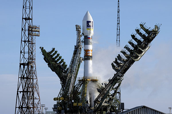
GIOVE-A was launched by Soyuz from Baikonur cosmodrome in Kazakhstan on Dec. 28, 2005. (Photo: ESA)
GIOVE-A Sped to Orbit
Galileo In-Orbit Validation Element-A, or GIOVE-A, was produced at a breakneck pace to meet this deadline. Developed in the second half of 2003, the satellite was designed, built and tested before the end of 2005, and launched on Dec. 28 of that year.
“At the time there was a lot of uncertainty: Would we make it or not?” recalled Javier Benedicto, head of the Galileo Project Department, ESA. “GIOVE-A transmitted its first Galileo signal-in-space on Jan. 21, 2006, meaning that Europe was formally in the navigation business.”
That March, ESA formally confirmed it had brought the Galileo-related frequency filings into use, three months ahead of the official ITU deadline.
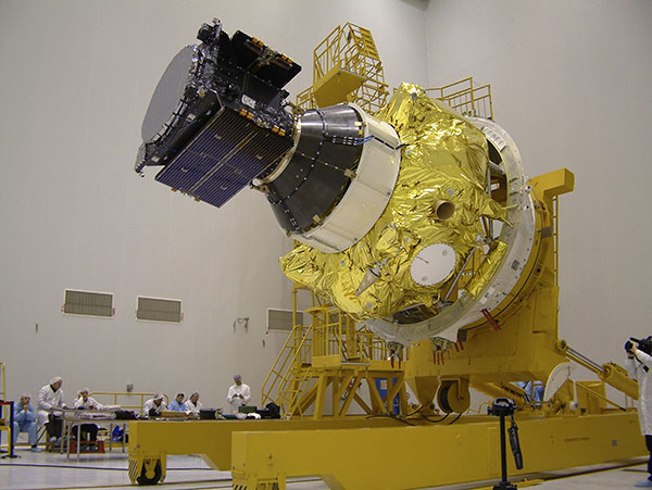
Europe’s first navigation satellite GIOVE-A, short for Galileo In-Orbit Validation Element-A, during flight preparation. (Photo: ESA)
The mission also carried a prototype rubidium atomic clock — proving its functionality for the operational Galileo satellites that would follow — as well as a radiation instrument. Medium Earth orbit, 23,000 km altitude, was terra incognita at this point for European satellites, but it was known to possess enhanced radiation levels from the impinging of the outer band of Earth’s Van Allen radiation belts.
A second Galileo prototype, GIOVE-B, followed in 2008, this time hosting a prototype passive hydrogen maser — the second type of atomic clock that Galileo relies on — along with an enhanced payload able to transmit for the first time the GPS-Galileo common signal.
GIOVE-A Succeeded at New Mission
Once the first Galileo satellites were in orbit and working well, ESA ended use of GIOVE-A in 2012. The satellite was placed in a graveyard orbit 100 km above the operational satellites’ orbits, as was GIOVE-B after its own four-year mission.
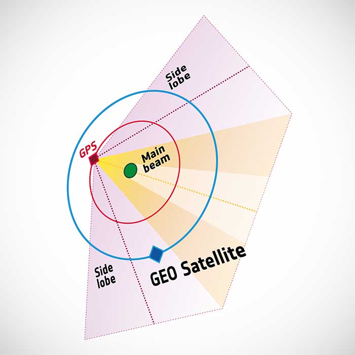
Control of GIOVE-A passed to manufacturer Surrey Satellite Technology Ltd (SSTL) in the United Kingdom. GIOVE-A was then employed for various in-orbit experiments, including demonstrating the reception of satellite navigation signals from GPS satellites orbiting below it — based on spillover sidelobe reception from satellites on the other side of Earth.
GIOVE-A was able to make use of signals emitted sideways from GPS antennas, within what is known as “side lobes.” (Image: ESA)
This proof that satnav can be relied on further out into space means that satellites in geostationary orbit are making use of satnav for positioning. As a next step, ESA is planning to extend satnav coverage all the way to the Moon.
The satellite also continued its radiation survey of medium-Earth orbit, acquiring a unique record extending across more than 10 years, analyzed by the Surrey Space Centre with ESA support. Multiple scientific papers have been written on these results, which encompass the “electron desert” of 2008-9 during the lowest levels of solar activity of the space era, followed by one of the largest electron storm events on record in April 2010.
A new model of the outer Van Allen belt electron fluxes, MOBE-DIC, has been produced from this dataset, helping to guide future satellite designs.
“Actually, the satellite itself is still operating well,” said Sarah Lawrence, SSTL. “The reason for ending the mission is software obsolescence in our control center. The decommissioning procedure involved transitioning the satellite to Earth-pointing mode, turning off the reaction wheels and setting the attitude and orbit control system to standby mode, before finally switching off the on-board computer and transmitter.”
“GIOVE-A over-delivered on its original lifetime and mission goals – an inspiring and game-changing mission on so many levels,” said Martin Sweeting, SSTL executive chairman.
SSTL went on to provide navigation payloads for operational Galileo satellites. Today, 26 Galileo satellites orbit the Earth. Galileo has become the world’s most precise satnav system, delivering meter-scale accuracy to more than 2.3 billion users around the globe.
The Launch Readiness Review on Nov. 26 confirmed that the satellites, the supporting ground installations, and the early operations facilities and teams are ready for lift-off on the early hours of Thursday morning, central European time.
UPDATE: Arianespace has postponed today’s launch and is now targeting launch on Friday (Dec. 3). Liftoff is set for Dec. 3 at 7:23 p.m. EST (0023 GMT).
Galileo satellites 27 and 28 are scheduled to be launched by a Soyuz launcher from Europe’s Spaceport in French Guiana on Dec. 2 at 01:31 CET (Dec. 1 at 21:31:27 local Kourou time).
These satellites are the first of Batch 3, comprising 12 additional first-generation Galileo satellites commissioned in 2017 to bring the constellation to full operational capability. They will be used to further expand the constellation up to 38 satellites and act as backups and spares for satellites that reach their end-of-life.
Follow the launch live on ESA Web TV Two starting at 0104 CET.
“Friday’s Launch Readiness Review confirmed that the first two satellites in this final batch of 12 Galileo first-generation satellites, are good to go, provided no external circumstances come up between now and the night of 1-2 December,” said Bastiaan Willemse, ESA’s Galileo Satellite manager, from Europe’s Spaceport in Kourou, French Guiana. “Meanwhile the preparation for the launch campaign of the next two satellites has already started.”
The Launch Readiness Review is an ESA-led review with participation of the satellite manufacturer OHB, the launch service provider Arianespace, the Galileo operator SpaceOpal, the EU Space Programme Agency (EUSPA) and the European Commission, as well as the programme’s Security Accreditation Board.
Friday’s review was the last before the Arianespace-led RAL (Revue d’Aptitude de Lancement) takes place next week when the latest status of the launcher, the launch facilities and site, the global launch tracking facilities, the satellites and supporting ground infrastructure will be reviewed, most likely resulting in approval for launch countdown.
The satellites arrived in French Guiana in early October, kicking off a busy launch campaign, including initial dispenser fit checks and the filling with the hydrazine fuel that will be used to maneuver them during their 12 years of working life.
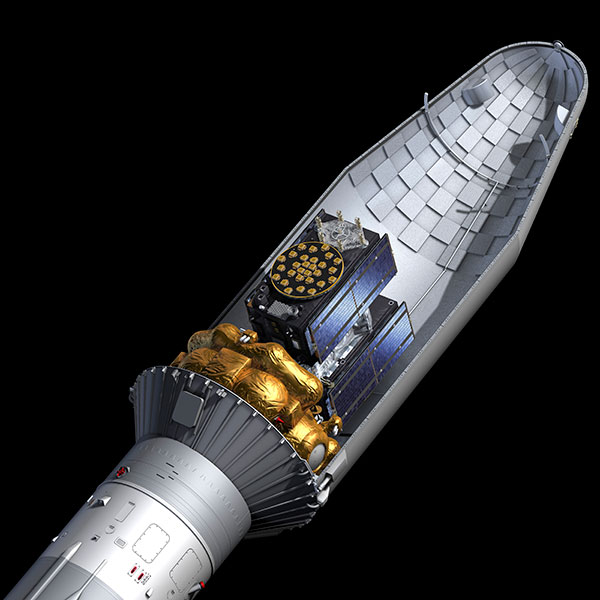
Galileos 27-28 seen atop their gold-wrapped Fregat upper stage within their Soyuz launcher fairing. (Photo: ESA)
The two satellites will add to the 26 satellites of the Galileo constellation already in orbit and delivering Initial Services around the globe.
This week’s lift-off will be the 11th Galileo launch in 10 years. Two further launches are planned for next year, to allow Galileo to reach Full Operational Capability in its delivery of services, to be followed by the launches of the rest of the Batch 3 satellites — all undergoing final integration at OHB facilities in Bremen and on-ground verification testing at ESA’s ESTEC Test Centre in the Netherlands.
In parallel to Batch 3’s completion of Galileo First Generation deployment, the new Galileo Second Generation satellites, featuring enhanced navigation signals and capabilities, are already in development with their deployment expected to begin by 2024.
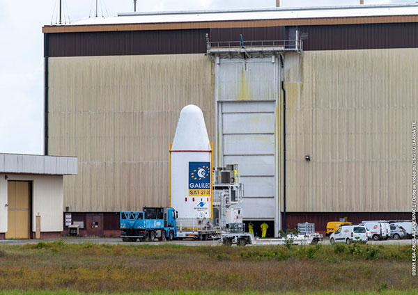
The combined upper composite for the Galileo launch being transported to the other three stages of the Soyuz at the launch site. (Photo: ESA)Galileos 27 and 28 are secured to the dispenser that holds them in place during launch. (Photo: ESA)The two Galileo satellites attached to the dispenser on which they will ride to orbit. (Photo: ESA)
Russia warned it could blow up 32 GPS satellites with its new anti-satellite technology, ASAT, which it tested Nov. 15 on a retired Soviet Tselina-D satellite, according to numerous news reports.
Russia then claimed on state television that its new ASAT missiles could obliterate NATO satellites and “blind all their missiles, planes and ships, not to mention the ground forces,” said Russian Channel One TV host Dmitry Kiselyov, rendering the West’s GPS-guided missiles useless. “It means that if NATO crosses our red line, it risks losing all 32 of its GPS satellites at once.”
The International Space Station (ISS) Flight Control team was notified of indications of a satellite breakup, causing 1,500 pieces of debris to threaten the station. “Due to the debris generated by the destructive Russian Anti-Satellite (ASAT) test, ISS astronauts and cosmonauts undertook emergency procedures for safety,” said NASA Administrator Bill Nelson.
“With its long and storied history in human spaceflight, it is unthinkable that Russia would endanger not only the American and international partner astronauts on the ISS, but also their own cosmonauts,” Nelson said. “Their actions are reckless and dangerous, threatening as well the Chinese space station and the taikonauts on board. All nations have a responsibility to prevent the purposeful creation of space debris from ASATs and to foster a safe, sustainable space environment.
“Russia has demonstrated a deliberate disregard for the security, safety, stability and long-term sustainability of the space domain for all nations,” Gen. James Dickinson, commander of U.S. Space Command, said. “Russia’s tests of direct-ascent anti-satellite weapons clearly demonstrate that Russia continues to pursue counterspace weapon systems that undermine strategic stability and pose a threat to all nations.”
Photo: Stanislav Ostranitsa/iStock/Getty Images Plus/Getty Images
“The tasks of paleontologists and classical historians and archaeologists are remarkably similar — to excavate, decipher and bring to life the tantalizing remnants of a time we will never see.” — Adrienne Mayor
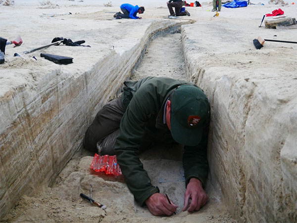
Heatwaves rose up from the dusty, dry, cracked ground. Tiny black flies buzzed around the team’s eyes and faces. The only shade was under a canopy erected across the shallow open trench where half a dozen people gently brushed away the layers. Dirt is time; the deeper one digs, the further back in time one goes.
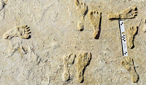
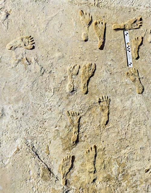
A layer 23,000 years old is exposed at nearly two feet down, revealing footprints of a female and a toddler. It tells a story of her mile-long journey through the soft clay mud. Roaming nearby was a giant sloth and a herd of mammoths. This discovery forces science to re-adjust the timeline of humans living on the North American continent, pushing it further back into the Pleistocene era at least 10,000 years.
Discoveries like this are the treasures archeologists seek. Archaeologists are scientists — part treasure hunters and part storytellers. They add context to history.
A trench dug into the brown gypsum soil on a lake playa in White Sands National Park reveals more human footprints below the surface. (Photo: National Park Service)
Ground-Penetrating Radar
Advanced technologies are aiding new discoveries of the past. Even though the footprints were buried beneath two feet of dirt, they were discovered without physically seeing them. Ground-penetrating radar (GPR) made the discovery possible. GPR has made significant advancements in recent years, along with improvements in other types of remote sensing applications.
The resolution of GPR has improved along with the depths that GPR can detect objects. Computers can process the GPR data into 3D images providing a depth profile of the scanned area. This is how the footprints were detected.
White Sands has the largest collection of fossilized human footprints. (Photo: National Park Service)
In addition to GPR, the researchers used magnetometers that verify disturbances in the sediment, which can also be imaged in 3D, albeit with a much lower resolution.
“The sediment itself has a memory that records the effects of the animal’s weight and momentum in a beautiful way. It gives us a way to understand the biomechanics of extinct fauna that we never had before,” said Thomas Urban, the Cornell University research scientist who led the team making the discovery.
Usually, archeological findings are of bones and artifacts. Fossilized “ghost” footprints of humans and other creatures brings them to life, providing glimpses of the living past.
Under ideal conditions, GPR can reach depths of 30 meters (98 feet). The accuracy and range of GPR depend on sediment type, moisture content and other geologic morphologies. Underlying GPR technology and magnetometry are robust geospatial information systems (GIS) that preserve a digital record of the discovery, allowing for further geospatial analyses. Advances in machine learning will improve future detection.
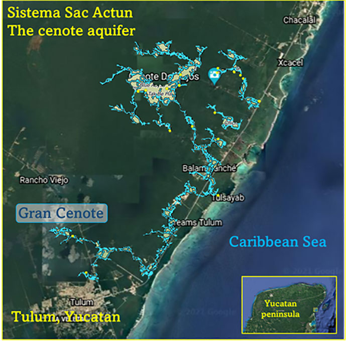
Elsewhere in the Americas, a project has been ongoing in Mexico since the 1990s using GPR to map the cenotes and underground aquifers used by the Mayans. A 215-mile-long underground water cave system — the longest in the world — has been mapped in the Yucatan peninsula. Divers exploring these cenotes found remains of Ice Age animals, including a sabertooth tigers and mammoths.
Map: William Tewelow
Lidar and ALS
Lidar (light detection and ranging) is making even more discoveries possible with the help of artificial intelligence and machine learning. For instance, in the jungles of Guatemala, lidar revealed the unknown ancient Mayan city of Tikal.
Lidar is an active sensor that measures ground height. Using an airborne laser scanning (ALS) system mounted to a plane, helicopter or UAV, the lidar device’s laser beams scan the landscape. The system calculates the time it takes for the beam to reach an object on the ground and bounce back.
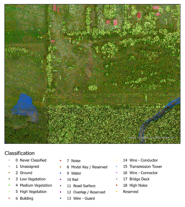
The result generates one point for each ground object the laser touches, calculating the distance the beam traveled. Billions of points are collected during a scan. Geospatial archeologists then process the collected points into a point cloud (Figure 1). Selecting only points classified as ground and water, the points are converted to a raster image, and archeologists are provided a perspective of the bare earth under tree canopy and vegetation (Figure 2).
In this way, lidar serves as a non-destructive way to identify earthwork formations, even in dense jungle.
Figure 2. Lidar points are converted to a raster providing a bare-earth representation of the landscape. (Image: Stephanie Clark)
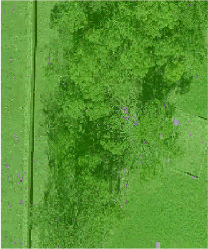
Figure 3. Pixel-derived object-based classification, developed using machine learning, identifies unmarked headstones from UAV-collected imagery. (Image: Stephanie Clark)
Object-Based Imagery Analysis
The challenge with lidar and imagery is the sheer volume of data, beyond the scope of what a human can manually review. Because of how faint archaeological features can be, the search often requires manipulating imagery datasets by combining multispectral bands, and then merging them with topographical data. To assist this huge endeavor, artificial intelligence is applied to pixel-based classification and object-based imagery analysis (OBIA) to highlight areas of interest for further study.
Dylan Davis, a Ph.D. candidate at Pennsylvania State University, spearheaded the use of OBIA for finding earthworks such as circular mounds, stone walls,and roadways in Beaufort, South Carolina. He took advantage of high-resolution NOAA imagery taken of the coast before the hurricane season of 2008. Using artificial intelligence for object-based imagery analysis, 160 previously undetected mound features were found.
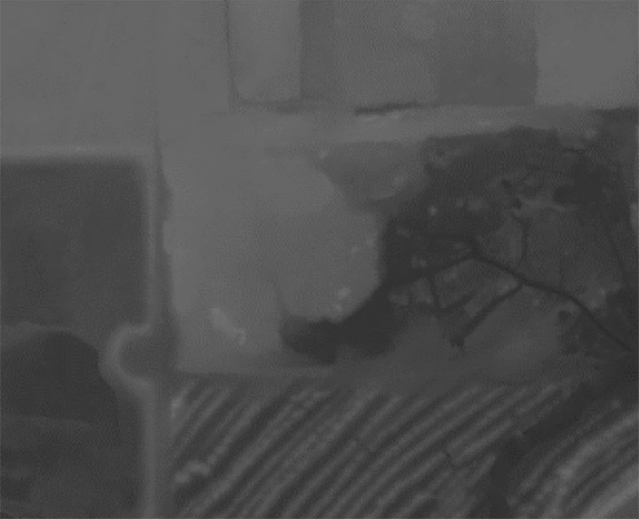
Raster comparison: Sea Pines Shell Ring, Hilton Head Island, South Carolina. Credit: Dylan S. Davis, Matthew C. Sanger & Carl P. Lipo (2018): “Automated mound detection using lidar and object-based image analysis in Beaufort County, South Carolina,” Southeastern Archaeology [https://doi.org/10.1080/0734578X.2018.1482186]On the local level, archeologists apply the same approach to finding headstones in unmarked cemeteries. A pixel-defined object-based classification system helped one researcher automatically identify potential headstones in a densely vegetated cemetery.
The technology used for OBIA is also used for visual-inertial odometry (VIO). NASA is experimenting with VIO techniques to help astronauts navigate the lunar surface (see NASA’s Artemis program will need lunar spatial reference system). For Artemis, VIO will use the Moon’s craters as a reference system to derive an accurate position.
Virtual 3D Worlds
Perhaps one of the most significant uses of technology for archaeological research and exploration is the use of virtual 3D immersive worlds. Exploring ancient worlds as they might have looked gives archaeologists additional insights and the public a chance to experience their discoveries, connecting us with history.
The mile-long journey of a young female carrying a toddler across an Ice Age landscape 23,000 years ago seems so distant, yet so familiar to any parent. The image breathes life into our common ancestry. Through the power of GIS and modern technologies, she walked right into the 21st century.
“The man who knows and dwells in history adds a new dimension to his existence…He lives in all time; the ages are his, all live alike to him.” — William Flinders Petrie
Special thanks to Stephanie Clark, a geospatial archeologist with Integrated Environmental Solutions, LLC, of Phenix City, Alabama. Stephanie provided technical advice and collaboration, and the lidar studies for Figures 1, 2 and 3.
William Tewelow is a senior aeronautical information specialist for the Federal Aviation Administration. He is a 2016 graduate of the FAA’s management fellowship Program for Emerging Leaders and a mentor with the FAA’s National Mentor Program. He served on special assignment to the U.S. Department of Transportation and led a national strategic geospatial initiative under the authority of the White House Open Data Partnership.
Tewelow is a designated Geographic Information Systems Professionals (GISP), with degrees in geographic information technology and Intelligence Studies. he is currently earning his master’s degree in organizational leadership with a focus on performance management.
Tewelow retired from the U.S. Navy after serving 23 years as a geospatial and imagery intelligence specialist, a naval aviator, a meteorologist and a tactical oceanographer earning three achievement medals. He was among the first in the nation to earn a Geospatial Specialist Certification from the U.S. Department of Labor while working at NASA Stennis Space Center. He is married, enjoys traveling, connecting people, and solving problems, and is interested in new technology. His favorite quote is, “A man’s mind changed by a new idea can never go back to its original dimension.” ~ Oliver Wendell Holmes










![<b>Raster comparison: Sea Pines Shell Ring, Hilton Head Island, South Carolina. </b>Credit: Dylan S. Davis, Matthew C. Sanger & Carl P. Lipo (2018): Automated mound detection using lidar and object-based image analysis in Beaufort County, South Carolina, Southeastern Archaeology [https://doi.org/10.1080/0734578X.2018.1482186]](https://stage.globalpositioningnews.com/wp-content/uploads/2021/11/Davis-SC-mounds-HiltonHead.jpg)