The U.S. President’s National Space-based Positioning, Navigation and Timing (PNT) Advisory Board will meet on December 9 and 10 at the Sheraton Pentagon City Hotel in Arlington, VA, according to a post on the group’s website.
The meeting is open to the public. Interested parties are encouraged to attend.
The agenda, while still not finalized, is expected to include a full day public meeting on Thursday, December 9, and a half day on Friday, December 10.
Previous in-person meetings have included program updates from government departments and briefings on cutting edge government and industry projects on the first day. The second day normally sees updates from international representatives and open discussion of current issues among the board members.
The Advisory Board’s size is expected to increase at this meeting with three previous members leaving and nine newly appointed members being added.
A formal announcement of the meeting is expected in the Federal Register on Monday, November 15. Confirmation of the new membership roster is expected at about the same time.
The PNT Advisory Board was established in 2004 by National Presidential Security Directive 39, “U.S. Space-Based Positioning, Navigation, and Timing Policy.” It operates under the rules of the Federal Advisory Committee Act and is tasked with providing advice “… on U.S. PNT policy, planning, program management, and funding profiles in relation to the current state of national and international space-based PNT services.”
The Advisory Board has regularly advised the government on all aspects of space-based PNT, including the need for a holistic “PTA” approach – “Protect” signals, “Toughen” user equipment, and “Augment” services with alternative PNT sources.
This will be the first in-person meeting of the board since November 2019. A virtual meeting was held in July 2020.
After the conclusion of the government Advisory Board meeting on Friday, December 10, the non-profit Resilient Navigation and Timing Foundation will hold its annual membership meeting and lunch at the same venue.
The Airbus A350 can now be equipped with the Collins Aerospace GLU-2100 multi-mode receiver. (Photo: pablorebo1984/iStock/Getty Images Plus/Getty Images)
The Collins Aerospace GLU-2100 multi-mode receiver (MMR) has received approval by Airbus, making it available as line-fit and retrofit on Airbus A320, A330 and A350 aircraft. This a major step toward Collins offering next-generation GNSS to the commercial aviation marketplace.
An MMR assists pilots in positioning, navigating and landing an aircraft. Building on the GNSS capabilities of previous MMRs, the GLU-2100 provides a satellite-based augmentation system (SBAS) and ground-based augmentation system (GBAS). This supports the integrity of the aircraft position, as well as the accuracy and availability of demanding aircraft operations such as landing in low visibility conditions.
The GLU-2100 MMR ensures that commercial aircraft can meet flight zone global mandates, while also proofing the technology by providing a solid foundation for future growth. It includes the flexible hardware baseline necessary to implement future GNSS capabilities, such as multi-frequency and multi-constellation (MFMC), and GBAS Category II/III via software-only update.
Acquisition of FlightAware tracking platform
In August, Collins Aerospace signed a definitive agreement to acquire privately held FlightAware, a digital aviation company providing global flight-tracking solutions, predictive technology, analytics and decision-making tools.
Closure of the acquisition is subject to the completion of customary conditions and regulatory approvals. Following closing, FlightAware will join Collins’ Information Management Services portfolio within the company’s Avionics strategic business unit. Financial terms of the agreement were not disclosed.
Based in Houston, Texas, with approximately 130 employees, FlightAware was founded in 2005 and is a provider of real-time and historical flight information and insights to the global aviation community. FlightAware serves all segments of the aviation marketplace through applications and data services that provide comprehensive information about the current and predicted movement of aircraft.
Through the collection, interpretation and enrichment of hundreds of sources of data, FlightAware transforms millions of raw flight data elements and delivers them as coherent, easy-to-consume flight stories. The company has a proprietary terrestrial ADS-B network with tens of thousands of receivers spanning seven continents in 200 countries and territories.
Fugro’s Blue Essence, an offshore certified uncrewed surface vessel (USV) with an electric remotely operated vehicle (eROV), will begin its first project in the Netherlands.
The vessel is controlled from an onshore remote operations center (ROC) via a satellite connection. It will be used for the inspection of offshore assets, construction support services, and hydrographic and geophysical surveys.
USVs play an important role in the future of the maritime sector by improving safety, reducing carbon emissions, and delivering data more efficiently. USV operations remove personnel from high-risk offshore environments to an onshore ROC and reduce carbon footprint by 95 % when compared to traditional survey methods. Cloud-based data processing allows near real-time data delivery, leading to faster and more informed decision making.
“We welcome this special vessel in our port. It’s the first time a remotely controlled uncrewed vessel will go to the North Sea from the port of Rotterdam to carry out a project without any personnel on board,” said René de Vries, Harbour Master of the Rotterdam Port Authority. “We are proud that this project will be executed safely due to the careful preparation of all parties involved. We expect the development of digitalization in the shipping sector will improve the safety and accessibility of the Rotterdam port.”
Since 2020, Fugro has been deploying its Blue Shadow USV fleet for medium- to large-scale hydrographic survey applications. Fugro’s first Blue Essence has completed its first remote inspection, in Asia Pacific.
“I am excited that we now also have this newest generation of USVs available for European clients,” said Erik-Jan Bijvank, group director Europe and Africa at Fugro. “Over the coming years, Fugro will further expand its fleet of USVs for safer, more sustainable solutions for marine operations.”
Trimble has established a scholarship program to honor Gladys West, a pioneer in mathematics, minority advancement and the advent of the Global Positioning System — one of the most widely used innovations throughout the world.
Gladys West. (Photo: Trimble)
Supported by the Trimble Foundation, a donor-advised fund, the Dr. West scholarship program will enable Virginia State University, North Carolina A&T State University and Florida International University to award a four-year scholarship to one student each year. These universities were carefully chosen to reflect Dr. West as a woman of color and science, and to align with two of the Trimble Foundation’s key support pillars: female education and empowerment and diversity, equity and inclusion.
Known today as the hidden figure who helped invent GPS, West knew from a young age that education would be the key to moving forward from her family farm in rural Virginia. A scholarship recipient herself, she earned a bachelor’s and master’s degree in mathematics.
She was offered a position in 1956 with Virginia’s Naval Proving Ground — now called the Naval Surface Warfare Center. Hired as a mathematician, she was one of only four African American employees at the time and only the second woman of color.
With her intelligence and computational skills recognized, she quickly climbed the ranks and became project manager for the Seasat radar altimetry project in the 1960s. Knowledge gained through that work enabled her to program an IBM computer to calculate an accurate geodetic Earth model — the detailed mathematical model of the shape of the Earth that is the essential building block for GPS.
That tenacity, talent and enterprising fortitude encapsulates the spirit of Trimble’s scholarship program designed to honor West’s contributions to science and the geospatial industry.
“It’s fitting to announce this special scholarship program following West’s 91st birthday,” said Rob Painter, Trimble CEO, “a woman who helped pave the path to GPS — the technology that was not only core for Trimble’s early business but provided the catalyst to create the geospatial industry. This path to innovation has given us the tools to not only navigate and model our world, but to transform work in our lives every day. Just as West viewed education as the pathway for the future, we are excited by the opportunity to support a new generation of stars to help them pursue their educational journey.”
“We must appreciate our past, learn in the present and prepare those behind us for the future,” West said. “We must encourage our youth to pursue a higher level education so that they will be equipped to change the world. We must be willing to use our talents and strengths to work for the betterment of the world.”
Virginia State University — West’s alma mater and a Historically Black College and University (HBCU) — will award the Dr. Gladys West “Constellation” Scholarship from Trimble to a student in the College of Engineering and Technology. The VSU scholarship is also being matched by an anonymous donor.
North Carolina A&T State University — a top-ranked public HBCU — will award the Dr. Gladys West HBCU Scholarship from Trimble to a student in the College of Engineering.
Florida International University — a minority-serving institution — will award the Dr. Gladys West Trimble Technology Lab Scholarship to a first-generation student in the College of Engineering & Computing. The scholarship is also being matched. FIU is the home to the recently established Trimble Technology Lab, which provides students hands-on access to Trimble technologies within the Moss Department of Construction Management.
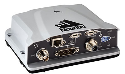
The PwrPak7-E1 from Hexagon | NovAtel is now supported on the Nvidia Drive Hyperion autonomous vehicle (AV) development platform. Selected for its robustness and precise position output, the PwrPak7-E1 will be offered with Nvidia’s autonomous driving test fleets worldwide.
Drive Hyperion is a fully operational, production-validated and open AV platform that reduces the time and cost required to outfit vehicles with autonomous driving and artificial intelligence (AI) features.
Powered by NovAtel’s OEM7 GNSS engine, the PwrPak7-E1 provides high-precision positioning used in the development of autonomous vehicles. The PwrPak7-E1 delivers NovAtel’s SPAN technology (GNSS + inertial navigation system, or INS) in an integrated, single enclosure.
Ground truth is the critical position reference for autonomous driving software behavior that can be validated. The PwrPak7-E1 provides ground truth in conjunction with Novatel’s Waypoint Inertial Explorer post-processing software. The device also has several connection options (serial, USB, CAN and Ethernet).
The GNSS and inertial measurement unit (IMU) output of the PwrPak7-E1, along with data from other onboard sensors, are recorded and fed into Nvidia’s sophisticated autonomous-driving development infrastructure and processing pipeline. There, data is synchronized, used for training AI models, and used in testing of various software components and autonomous driving behavior.
“Drive Hyperion is designed to give developers the ability to develop, evaluate, and validate AV technology more quickly,” explained Glenn Schuster, senior director of sensor ecosystems at Nvidia. “NovAtel’s compatibility on our platform provides developers the confidence to synchronize their sensor data with precision location information.”
Galileo Control Centre in Oberpfaffenhofen, Germany. (Photo: ESA)
Spirent Communications plc has launched a commercially available simulation test solution for the Galileo High Accuracy Service (HAS), via a beta interface implementation based on HAS ICD version 1.2. During the development of the solution, Spirent collaborated with GMV, a leader in cutting-edge GNSS high-accuracy technologies.
Galileo HAS will provide free-of-charge high-accuracy Precise Point Positioning corrections through the Galileo E6-B signal, with accuracy under two decimeters, offering real-time improved user positioning performance. Developers need to be able to test their devices against this new service to ensure they can optimally capture the emerging capability when it becomes available. By integrating HAS simulation and capabilities, Spirent’s latest simulation solution enables customers to utilize and incorporate Galileo HAS as early as possible.
In February 2021, the European Union Agency for the Space Programme (EUSPA) awarded GMV with the contract for the implementation of the Galileo High Accuracy Data Generator (HADG), which will be the facility in charge of generating the high-accuracy corrections data to enable the provision of HAS. Spirent’s collaboration with GMV will prove a key element in the early adoption of the service.
“The high accuracy, feature richness and flexibility of Spirent’s simulator platforms provides an ideal foundation for the testing of innovative new Galileo services such as our recent Galileo HAS capability,” said David Calle, section head of advanced GNSS services at GMV’s aerospace sector.
“The high level of expertise and in-depth understanding of Galileo HAS within GMV provided important guidance as we implemented HAS on our simulation platform,” said Jan Ackermann, Spirent’s director of product line management. “This enabled us to again be the first in the industry to offer a commercial solution to simulate and test these important new capabilities.”
Spirent Federal announced a new positioning, navigation and timing (PNT) test capability commonly referred to as programmable power — or flex power — available at no additional cost to qualified customers under support. The new capability allows the user to apply flex power configurations to existing scenarios.
Flex power is the reallocation of transmit power among individual signals in GPS satellites, providing a countermeasure against GPS jamming. Spirent simulators fully support programmable power for M-code, Y-code and C/A (coarse acquisition) code.
“From the time that we ascertained the need for flex power simulation, to the delivery of a completed easy-to-use utility, was a very short time,” said Ellen Hall, president and CEO of Spirent Federal. “It is this kind of responsiveness that we strive for here at Spirent Federal, so we can pass along the benefits to our customers.”
Flex power is available on the Spirent GSS9000 GPS / GNSS constellation simulator.
By Brandon Weaver, Gianluca Zampieri and Okuary Osechas
Innovation Insights with Richard Langley
IT’S A FACT. GPS and its brethren global (and regional) navigation satellite systems are susceptible to outages caused by both natural and engineered events. Several reports issued in the past couple of decades have documented the vulnerability of GNSS. Twenty years ago this past August, the U.S. Department of Transportation’s John A. Volpe National Transportation Systems Center issued a report, commonly referred to as the Volpe Report, in which they found that “GPS service is susceptible to unintentional disruptions from ionospheric effects, blockage from buildings, and interference from narrow and wideband sources.” Although not explicitly mentioned in the report, besides emissions from communications systems, wideband interference can come from solar radio noise storms overpowering GPS signals. The report also highlighted that the “GPS signal is subject to degradation and loss through attacks by hostile interests. Potential attacks cover the range from jamming and spoofing of GPS signals to disruption of GPS ground stations and satellites.”
The Volpe Report recommended a number of actions to mitigate the vulnerabilities of the GPS signal to disruption or loss, including the need for backups for positioning, navigation and timing — particularly for GPS applications involving the potential for life-threatening situations such as the loss of GPS use for safety-of-life navigation, which would include, for example, aircraft navigation.
With the introduction of GPS (and subsequently the other GNSS and their augmentations) and its widespread adoption by the aviation industry, legacy navigation systems such as Omega, aviation radiobeacons, VHF Omnidirectional Range (VOR) and Distance Measuring Equipment (DME), were either shut down, reduced in their number of installations, or displaced as the primary method of navigation. These systems could not offer the same capabilities as GNSS, and that has led to the high reliance now on GNSS for getting aircraft safely from one airport to another.
But as the Volpe Report pointed out, GPS and (by inference) all other GNSS are susceptible to outages, and so a reliable alternative PNT system that can be readily used for aircraft navigation is needed. Deutsche Flugsicherung, the German air traffic control organization, has proposed such a system, called Mode N. It builds on some aspects of existing navigation systems and aviation-certified signals not originally intended for navigation, including some used for communications and surveillance.
In this month’s column, a team of researchers from the German Aerospace Center introduce us to Mode N, looking at its signal format, required ground infrastructure, aircraft avionics and the potential position accuracy this system could offer.
To accommodate the continued growth of air traffic, air navigation service providers (ANSPs) are planning and implementing programs to increase the capacity and efficiency of airspace. These programs, which include the Next Generation Air Transportation System (NextGen) led by the U.S. Federal Aviation Administration (FAA) and the Single European Sky ATM (Air Traffic Management) Research Programme (SESAR) commissioned by the European Union, heavily rely on GNSS to enable certain capabilities to reach program goals. While intended to serve as the primary source of positioning, navigation and timing (PNT) for aviation services going forward, GNSS is vulnerable to sources of interference. For this reason, efforts have been taken to identify and develop an alternative PNT (APNT) system that can maintain capabilities supported by GNSS when a GNSS outage occurs.
The ANSP for Germany, Deutsche Flugsicherung (DFS), has proposed a concept for such a system that they call Mode N. The proposed design leverages current navigation and surveillance technology to provide a completely new solution to navigation. As the current APNT environment is filled with a variety of proposed solutions spanning the entire field of communications, navigation and surveillance (CNS) technologies, it is useful to describe Mode N within the context of these other APNT systems. This contextual description serves to highlight the interaction of Mode N with current aviation systems — an important consideration for any system intended to serve aviation users. Additionally, as the Mode N design uses similar technological principles as other navigation and surveillance systems, the extensive research performed for APNT can be applied to the Mode N design to provide a preliminary assessment of its navigation performance over Germany.
Development of APNT
The current state of aviation navigation can be simplified by acknowledging that GNSS has replaced legacy navigation systems such as Distance Measuring Equipment (DME) and VHF Omnidirectional Range (VOR) beacons as the primary method of navigation for aircraft. GNSS PNT services enable many capabilities in the airspace that are relied upon by modernization efforts to accommodate the expected increase in air traffic in a safe and efficient manner. Because of GNSS vulnerabilities outlined in the 2001 Volpe Report, it was recognized that an alternative system that could enable the same capabilities as GNSS would be necessary to continue safe and efficient operation of airspace as envisioned if GNSS is unavailable.
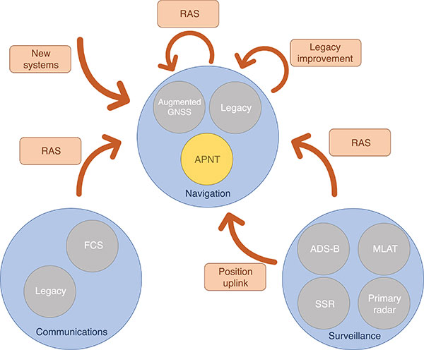
Proposed APNT solutions are generally sourced from the existing CNS environment. A common strategy is to use an aviation-certified signal not originally intended for navigation, which we have termed repurposed aviation signals (RAS). Other proposals include improving legacy systems, transmitting the ground-computed position to an aircraft, and creating new systems entirely. These sources of APNT are summarized in FIGURE 1 with explanations of the abbreviations to follow.
FIGURE 1. Sources of APNT for navigation. (Image: Weaver et al)
A natural candidate for APNT is the use of existing non-GNSS navigation infrastructure. Prior to GNSS, VOR beacons providing beacon-relative heading information and DME navaids supplying two-way range information were the primary navigation infrastructure. Improvement in DME avionics enabled tracking of multiple DME stations, providing a DME-only position solution referred to as DME/DME. Adding DME ground stations and upgrading existing hardware to increase accuracy and coverage of DME/DME positioning was therefore an attractive APNT option.
Another option sourced from the existing navigation infrastructure was to use RAS for positioning. One such RAS is that of the DME reply signal to a non-existent aircraft. By triggering DME responses in a desired fashion, aircraft can use the triggered responses for passive ranging without any change to the DME ground stations.
Communication systems for aviation are also undergoing modernization efforts. Future communication systems (FCS) are being developed to provide broadband communication capability between aircraft and controllers.
Surveillance is the domain of ground-based systems that determine the position of remote objects and is fundamental to allowing safe spacing of aircraft. Its origins reside in the development of primary radar, which was then complemented with secondary surveillance radar (SSR). Both primary radar and SSR use a rotating antenna to measure range and bearing to determine the location of the remote objects. Radar systems tend to be clustered around airports, limiting their area of coverage. To expand coverage in challenging terrain where radar is difficult to install, a technique known as multilateration is used, where a surveillance ground system can receive a signal from an aircraft and determine its position by comparing the time of arrival (TOA) of the signal between its ground stations. These systems were considered as a source of APNT by providing the aircraft position computed on the ground back to the aircraft via data uplink, but timely authentication and integrity concerns have stalled this approach in the United States.
Surveillance RAS for APNT. The other branch of surveillance-sourced APNT is by using RAS, and this is very relevant to the design of Mode N. The system providing many of the RAS for navigation is ADS-B. With this service, an aircraft broadcasts its GNSS-derived position (ADS-B Out) to ground-based stations and any aircraft capable of receiving ADS-B transmissions. ADS-B is an important part of airspace modernization strategies; it is mandated for aircraft operating in most U.S. airspace, with European mandates following suit. ADS-B ground stations, referred to as ground-based transceivers (GBT) or radio stations (ADS-B RS), collect ADS-B Out messages for use by air traffic operators. These ADS-B RS also provide their own transmissions for use by aircraft that can receive ADS-B broadcasts (ADS-B In capability) and include weather information, nearby air traffic and so on.
ADS-B can use different protocols to transmit its signals. The Mode S (S for selective) protocol was designed to allow SSR ground stations to selectively interrogate aircraft in their coverage area, reducing congestion on the reply frequency. The Mode S reply format consists of a four-pulse preamble and a data block containing either 56 or 112 information bits for the aircraft to provide information dependent on the interrogation received. Mode S is internationally standardized, and an extended format known as Mode S Extended Squitter was adopted for Automatic Dependent Surveillance Broadcast (ADS-B) services. Mode S Extended Squitter or 1090ES (as it’s transmitted exclusively on 1090 MHz) is also used by the ADS-B RS that rebroadcast ADS-B Out (ADS-R) and provide traffic information services (TIS-B) to nearby aircraft with ADS-B In capability.
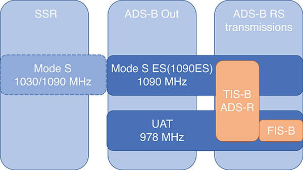
Another protocol, used in the United States, is the Universal Access Transceiver (UAT) format. Like 1090ES, UAT is used by certain aircraft to transmit their ADS-B Out messages. Similarly, ADS-B RS transmits TIS-B and ADS-R messages with the UAT protocol; it also includes additional information that it transmits with the Flight Information Service – Broadcast (FIS-B). UAT signals are transmitted in the United States on an unused DME channel frequency of 978 MHz. FIGURE 2 summarizes the relationship between these surveillance signals and the services that use them.
FIGURE 2. Services using Mode S and UAT signal formats.(Image: Weaver et al)
Research investigating the ground-transmitted (ADS-B RS) 1090ES and UAT signals for ranging measurements greatly supports the assessment of Mode N presented here, as the Mode N system operates on a similar basis with a signal that blends characteristics of 1090ES and UAT.
Mode N Overview
Mode N (N for navigation) is a passive ranging system concept from DFS that seeks to provide APNT while reducing the spectrum congestion caused by existing aeronautical navigation and surveillance systems. The design includes the possibility for two-way and air-to-air ranging, but this overview focuses on the preferred passive mode of operation. It is designed around the Mode S format, which as mentioned, is used for SSR and ADS-B services. Despite early references to an SSR/N system, Mode N is not a new SSR mode but rather a new navigation system.
The basic concept is for Mode N ground stations to transmit on a single frequency signals that include ground station ID/coordinates, allowing aircraft with Mode N avionics to receive those signals and determine position in a similar manner to GNSS. As a single frequency is desired to minimize spectrum usage, the ground stations would space their transmissions apart to avoid intersystem interference. This scheme, known as time division multiple access (TDMA), would require information within the signal message on the scheduled time a ground station transmits, which the Mode N format allows.
Because Mode N shares many design aspects with Mode S, DME and other surveillance RAS, it is able to leverage previous APNT work for the benefit of its own analysis. Therefore, the overview of the design is described here relative to other APNT systems, as this is the basis of the preliminary performance assessment we present.
The Mode N Signal. The Mode N design proposes using the Mode S downlink signal format as the basis for its ranging signal to be used by the aircraft for passive position determination, with some key differences. The frequency channel on 1090 MHz is too congested to accommodate more signals; thus, the first difference is that Mode N intends to transmit on a different frequency. While the channel selection is still ongoing, unused DME channels have been identified as options for frequency allocation.
The second difference is the message content. As the Mode S downlink format transmits mainly aircraft-specific information, Mode N ground transmitters would instead populate their messages with information needed for passive ranging: ground station coordinates and time of transmission (TOT). The study of 1090ES messages (which also contain aircraft-specific information despite being transmitted by ground stations) as RAS required some special techniques to first identify which station was transmitting the message. The TOT is not present in 1090ES signals, but more importantly the time of transmission is not synchronized to any consistent reference. Aside from transmission frequency and message content, the Mode N signal design follows the Mode S downlink format (modulation, pulse shape and so on).
The Mode N signal also shares some aspects with the UAT signal, particularly the FIS-B segment. First, UAT is also transmitted in the United States on an unused DME channel. The FIS-B message, which provides weather information, transmits the ground station coordinates and information that can be used to estimate the TOT. Specifically, UAT messages are synced to UTC, and each ADS-B RS has a designated time slot within a one-second interval where it transmits its FIS-B message. This time slot is included in the message, and can be used to determine the TOT of the signal. Mode N is designed to work in this exact manner, minus the weather information. One crucial difference between UAT and the Mode N design is the type of modulation. Like Mode S, Mode N proposes using pulse-position-modulation (PPM) or on-off keying (OOK). The resulting wider bandwidth — estimated to be less than 4.6 MHz at –3dB — has better resistance to multipath, whereas UAT is frequency modulated to maintain a narrow bandwidth to avoid interference with DME and is more susceptible to multipath. Research on UAT signals for pseudoranging capability (also determined at a higher update rate than once per second) would be necessary for navigation, an important consideration for the final Mode N design.
Ground Infrastructure. The Mode N design, while based on RAS from the surveillance capability, requires new ground stations to transmit the Mode N signal. Requirements for the ground stations are that they provide adequate coverage to meet the requirements of an APNT system and that they are sufficiently synchronized in time. An initial time-synchronization scheme is the use of a radio frequency (RF) network consisting of the ground stations themselves, which requires radio line-of-sight of stations throughout the network. DFS performed a study and found that additional time-beacon stations would be necessary to maintain this RF time network, even though navigation coverage was provided using existing DME sites as hypothetical Mode N stations. Since these aspects of the design are still developing, the preliminary assessment we present assumes a network layout and time synchronization tolerance. As the Mode N design blends various CNS principles, a natural baseline design for the ground station locations consists of existing DME and surveillance sites in Germany. Using these locations for the ground stations enables computation of a horizontal dilution of precision (HDOP) at discrete locations throughout Germany. The assumed time synchronization is discussed further when developing a model of the Mode N ranging accuracy.
Avionics. An interesting aspect of the Mode N design is its proposed avionics unit. The Mode N avionics must be capable of receiving Mode N messages, which it can do with the existing DME antennas on aircraft. The Mode N avionics unit must then decode the messages for position determination. Its active mode for two-way and air-to-air ranging would require the Mode N avionics to transmit Mode N messages, again using the existing DME antenna.
Recognizing the continuing investment in the DME network by multiple countries, the Mode N avionics sensor is essentially built around a fully functional DME unit. This is intended to provide a seamless transition as Mode N stations are brought on line. The design of the avionics has little effect on the coverage assessment, aside from guaranteeing a minimum level of performance based on the current DME network, but is an important part of the implementation strategy. Furthermore, this blend of avionics has also been proposed for a unit compatible with DME and ADS-B (1090ES and UAT) signals.
Preliminary Coverage Assessment
Preliminary coverage assessments are a typical method to determine the feasibility of a proposed system to provide the required level of performance over a given area. A simple method of characterizing the position performance is in terms of the linear relationship between range error and DOP, where the range errors are assumed to be zero-mean, uncorrelated, and have identical distributions.
As the aircraft is assumed to have additional sensors for determining its altitude, HDOP is commonly used to characterize the expected horizontal position performance.
With range measurements, HDOP is a function of the transmitter geometry available to an aircraft at a given point. It is a straightforward computation to perform for a grid of points over the area of interest. The HDOP computation does depend on the type of range measurement, so passive (pseudo-) range, two-way range, and time difference of arrival (TDOA) measurements all have their corresponding DOP computation. Determining a model for the range error is less straightforward, and assessing the coverage potential of Mode N requires an estimation of the expected range error.
Modeling Mode N Range Accuracy. As Mode N is not an existing system, abundant quantities of real measurements are unavailable for empirically characterizing the range performance. However, since Mode N is heavily based on the Mode S signal format and functions similarly to the DME and UAT signals, which all exist and have been measured extensively, research investigating those signals can help derive the model for the Mode N range performance.
An alternate approach is to reference the standards for a specified performance level. For example, ICAO documentation specifies that the Airborne Collision Avoidance System (ACAS) logic use a zero-mean normal distribution range error model with a standard deviation of 50 feet, or about 15 meters. As ACAS also uses the Mode S signal format, this appears to be a reasonable source for the Mode N range error. However, since ACAS is an airborne two-way surveillance method, it does not exactly translate to a ground-based passive TDOA system such as Mode N. The 15-meter standard deviation is still useful, as it provides a check on the estimated Mode N accuracy. Other specifications suffer from similar drawbacks — Mode N does not directly apply to any single system. Thus, we apply the blended approach using previous APNT research.
The fundamental measurement for the passive ranging mode of Mode N is the TDOA between pairs of ground stations. This measurement is in seconds, and is translated to a range difference by using the speed of radio signal propagation in a vacuum. (See our conference paper for further details.)
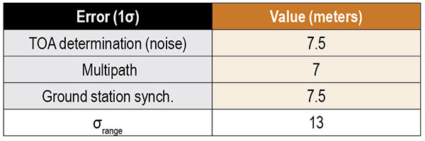
Errors can be present in the TOA measurement, synchronization of the nominal TOT of the signals, and parsing of the time slot data field. The TOA measurement can have errors by inaccurate determination of the actual TOA due to noise or multipath and by the actual TOA differing from the nominal arrival time of the signal due to atmospheric delay. For terrestrial systems, propagation errors are considered to be dominated by multipath, so we don’t consider atmospheric effects here. Time synchronization errors are very important to the ranging accuracy, but it is assumed the time slot data field is parsed accurately. Other sources of error, such as inaccurate ground station coordinates, can affect the position error but have no effect on the range error. Additionally, the error originating from the change in aircraft position between reception of signals at ground stations is not considered in this article. The model of range accuracy can then be expressed as the root-sum-square (RSS) of the dominant individual error components.
We studied each error component in isolation, selecting the applicable APNT research to leverage based on the Mode N design aspect that most corresponds with that error.
Since the Mode N design also uses a pulsed signal, the evaluation of DME (specifically, DME/N) ranging performance is the starting point for estimating the TOA noise error. Part of the APNT effort was evaluating current DME performance, as it was thought it exceeded the specified performance in standards. A study found that current DME performance allowed a budgeted TOA error of 15 meters, 2σ.
For the Mode N error model, a 7.5-meter error is an attractive option to choose as it is the average of two other sources and is the most recent. This value is a conservative estimate of the TOA accuracy for Mode N because the Mode N/S pulse shape is narrower than the DME pulse with a greater bandwidth, improving theoretical accuracy. For the preliminary coverage assessment, a conservative estimate is desired, because the actual TOA accuracy will vary over an area depending on transmitter distance — which impacts the level of signal noise. Note that the DME TOA errors are not divided by two as is done for the total DME error as they apply to a one-way TOA measurement.
After assessing the relevant studies, we modeled the multipath component of the error following that from Mode S as 7 meters, 1σ.
The final error component to estimate for Mode N is that of the synchronization of the ground stations. Based on the results from studies of the UAT signal and those from eLoran, we set a 15-meter maximum bias as a 2σ error component in the Mode N error model.
Our error analysis is summarized in TABLE 1.
TABLE 1. Predicted Mode N range accuracy. (Data: Weaver et al)
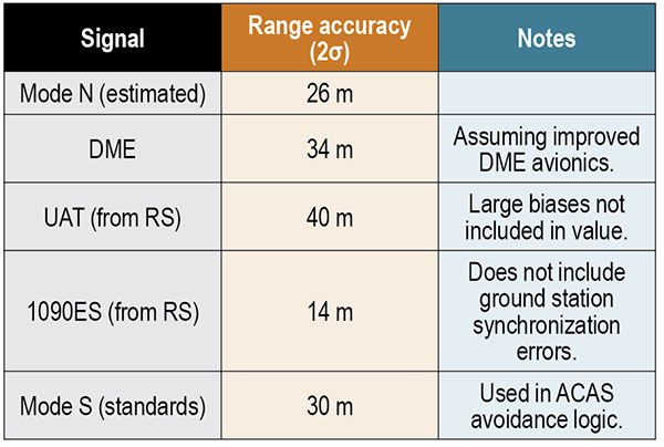
A total 2σ error for current DME performance of 92 meters has been established, which translates to 46 meters of range accuracy after dividing by two (since the DME signal is a two-way range). A substantial part of this error derives from the avionics bias, which is minimized for a “potential” DME error budget due to an assumed improved avionics performance. This results in a DME range 2σ error of 34 meters. We chose this value to compare as the effect of avionics has less of an impact in a passive ranging system such as Mode N.
Range performance for UAT signals was evaluated with measurements showing 20-meter (1σ) error when compared to GNSS truth, not including large biases attributed to ground station synchronization or processing errors. The 1090ES signals do not have an inherent ranging capability, so the TDOA measurement error of two ground station signals to one receiving station is difficult to measure. Instead, researchers have measured the differential TOA (DTOA) of one ground station signal received by two (GPS-synchronized) receiving stations to first identify which station transmitted the signal. When compared to the true DTOA based on ground station and receiving station coordinates, the measurements contained small biases around 10 meters with a standard deviation also less than 10 meters. Being DTOA measurements, these do not contain ground station synchronization errors, so the reported standard deviations correspond mostly with propagation and determining TOA. The 10-meter DTOA 1σ error can still be converted to a range error resulting in 14 meters (2σ). These results are summarized in TABLE 2.
TABLE 2. Comparison of Mode N with other APNT signals. (Data: Weaver et al)
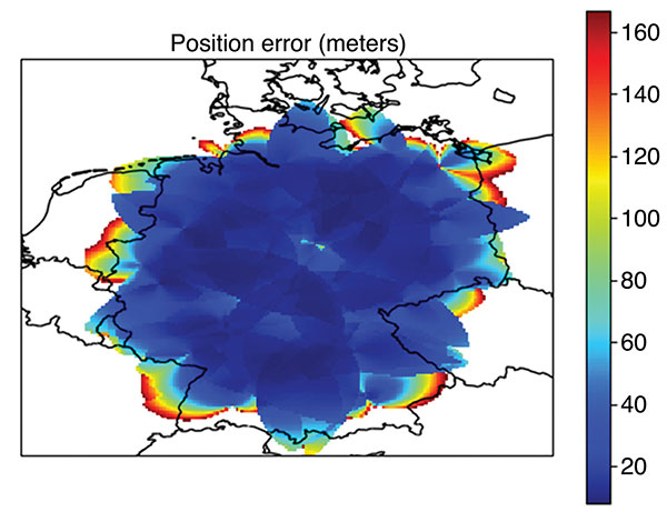
Coverage Assessment. With the estimated ranging accuracy, a preliminary coverage over Germany could now be assessed. Using the current 29 surveillance site locations in Germany and assuming that a minimum of three stations is necessary for positioning, the estimated position accuracy is shown in FIGURE 3.
FIGURE 3. Estimated position error (in meters) for aircraft within a 100 nautical mile coverage radius using existing surveillance sites as installation locations for Mode N ground stations. (Image: Weaver et al)
The coverage assessment used a “flat” Germany model with the estimated range accuracy from the preceding section (13 meters, 1σ). Atmospheric and terrain considerations were not applied in the assessment. It is important to note that this level of coverage would degrade at lower altitudes.
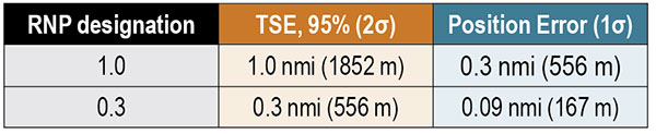
To determine whether this level of accuracy is sufficient for the airspace modernization efforts in Europe, the desired Required Navigation Performance (RNP) accuracy requirement must be examined. For RNP 1.0, where 1.0 refers to the required 95% or 2σ total system error (TSE) accuracy in nautical miles, the position error allocation is assumed to be 30% of the RNP/TSE value. The required position accuracy is shown in TABLE 3.
TABLE 3. RNP required horizontal position accuracy. (Data: Weaver et al)
From Figure 3, aircraft at altitudes within the service volume supported by a 100-nautical-mile coverage radius are capable of meeting the accuracy requirement for RNP 1.0 and 0.3 within most of Germany. Coverage along the border is unavailable as only German surveillance site locations were used.
Conclusions
Although our derivation of accuracy and the coverage assessment method we used made several simplifying assumptions, the results indicate that Mode N has the potential to be a feasible APNT system. To be a part of the modern airspace navigation infrastructure, additional accuracy requirements must also be met. The integrity requirement is harder to meet than accuracy, and requires either redundant information available to the aircraft for a receiver autonomous integrity monitoring-like algorithm or a ground-based monitoring/augmentation system. Perhaps the biggest challenge to implementing the Mode N infrastructure is maintaining an RF-based time synchronization network. Convincing aircraft operators to update their avionics is another challenge to Mode N implementation, although the inclusion of DME functionality in the Mode N avionics seeks to ease that transition.
DISCLAIMER
The views expressed herein are those of the authors and are not to be construed as official or reflecting the views of Deutsche Flugsicherung.
ACKNOWLEDGMENT
This article is based on the paper “An Overview of the Proposed Mode N System in the Context of Alternative Position, Navigation, and Timing (APNT) Development” presented at ION ITM 2021, the virtual 2021 International Technical Meeting of The Institute of Navigation, Jan. 25–28, 2021.
BRANDON WEAVER is a researcher at the German Aerospace Center (DLR) and works on alternative navigation systems.
GIANLUCA ZAMPIERI joined the Alternative Navigation Systems Group at DLR’s Institute for Communication and Navigation in 2019.
OKUARY OSECHAS leads the Alternative Navigation Systems Group in the Institute of Communications and Navigation at DLR.
“Original equipment manufacturer (OEM)” is a widely used but poorly defined term. In general, it refers to a manufacturer that provides components or sub-assemblies to another one for use in the latter’s end products. In the GNSS industry, the purchasers of OEM boards typically are manufacturers of products that require positioning or navigation capabilities, such as guidance systems for tractors, UAVs or automobiles. Sometimes, such manufacturers integrate the OEM GNSS receivers with other sensors, such as inertial measurement units and lidar devices. Often, the OEM also will provide technical support to the integrator.
Much of the OEM business is not visible to the end user of the equipment that contains OEM components, let alone to the casual observer, because those components are “inside the box,” such as a guidance system, and “the box,” in turn, is under the hood or in some other hidden place. There is almost never a sticker on the outside analogous to the one that says “Intel inside” on many computers to distinguish the Intel CPU inside from, say, an AMD processor. Furthermore, OEM sales are typically obscured by confidentiality provisions in OEM licensing agreements that also address issues of branding, payment, quality assurance, and the timing of deliveries.
Integrators can choose from a wide variety of OEM GNSS boards depending on their intended use; the environment in which they will operate; their performance requirements; and their size, weight, power consumption and (of course) cost. OEM GNSS boards range from development kits that assist users to integrate GNSS into their product design to differential, multi-frequency, and, increasingly, multi-constellation boards.
In the following pages, six GNSS OEM manufacturers address these questions:
How do you define OEM?
What distinguishes your latest generation of OEM receiver boards from previous ones?
What are the markets for your GNSS OEM receiver boards? Which ones are growing the most?
Additionally, each one showcases a product.
JAVAD GNSS Ready for Lift-Off
JAVAD GNSS has been transitioning to a new position in the market since the passing in May 2020 of its founder, president and CEO Javad Ashjaee, a giant of the GNSS industry. For several decades, the company eschewed mass production for such markets as the automobile industry and cellular phones, choosing instead to focus primarily on high-accuracy surveying applications.
“Our founder really loved the surveying market, created a lot of technology, and drove the rest of the industry through the evolutionary process to where it is today,” said Tom Hunter, the company’s chief sales officer. “You can see a little bit of JAVAD GNSS in just about any GNSS-based land survey product on the market today.”
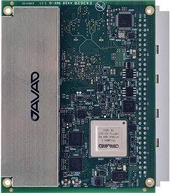
At the heart of each of JAVAD GNSS’ OEM boards is a proprietary ASIC. The boards it sells are the same ones it uses in its own reference stations, land survey products and marine systems, Hunter said. Aerospace is a key focus, an industry that requires very high accuracy, precision and reliability despite operating in environments of extreme shock, vibration, acceleration and temperatures.
Photo: Javad GNSS
“Our successes have been in working with many of the companies that build these very large launch vehicles used to carry heavy payloads into orbit,” Hunter said. “Our customers are companies such as Orbital, Northrop Grumman and SpaceX.” Those heavy-duty launch vehicles, he pointed out, must also follow a pre-described flight path. “You don’t want to start another world war because another country sees something heading its way.”
Tracing All Components. JAVAD GNSS’ boards “have complete component traceability,” Hunter said. The company does not buy any of its components from brokers. “We have to buy either directly from the manufacturer or from the manufacturers’ designated distributor, and it has full part traceability in our own factory in San Jose, California.” Should a component ever fail, the company could quickly trace when and where it was made. “That’s very important when we’re dealing with customers such as NASA, the Air Force or Boeing, because the safety of flight depends upon the performance and the quality of the product.”
The company will soon supply a receiver that will spend about four and a half to five years in orbit on a cluster of small low-Earth-orbit satellites, Hunter said. (See “JAVAD Board Guides ESA Vega Mission” below.)
To make sure none of its products are exported illegally from the United States, JAVAD GNSS also traces where each one ends up. “We know where every one of those boards is.”
JAVAD GNSS must guarantee its aerospace customers, which have invested millions of dollars in designing their systems, that each model of its devices will remain exactly the same. Hence, it bought from some manufacturers their entire inventory of certain components, in case they discontinued making them, and certifies each
JAVAD GNSS’ products are more expensive than those from other manufacturers because they are better, Hunter claimed. “We use really high-performance, temperature-compensated oscillators in our boards to make sure we have precise timing. We use a custom ASIC that we designed and built. Our receivers have 864 channels, so they can receive just about anything broadcast in the L-band.” The company constantly upgrades its devices to match modernization of the signal structures.
“I can remember when the rest of the industry was saying, ‘You have a 12-channel GPS receiver? You’re nuts! I mean, who uses that much information?’,” Hunter recalled. “Today, we’re using every signal that comes out of GPS, whether it be L1, L2, L5, L1C, and the same thing with all of the GNSS constellations.” For example, when Japan will begin to broadcast its new QZSS signal soon, “we’re ready not only to find it, but to track it, decode it, and utilize it for position and timing solutions.” Anti-jamming and in-band interference rejection are standard in JAVAD GNSS’ products, while those from other manufacturers require external filtering or different types of antennas, Hunter pointed out.
New Leaders and Markets
After Javad Ashjaee — JAVAD GNSS’ founder, president and CEO — died in May 2020, Tom Hunter, who co-founded Ashtech with Ashjaee in 1987, returned to the company after a five-year retirement.
“He left the company with an awful lot of technology, a lot of patents, and a lot of people who knew how to design and build products, not only for today, but for the future,” Hunter explained. “They needed some guidance.”
So, in January, Nedda Ashjaee — Javad Ashjaee’s daughter and his close collaborator for the previous 25 years — and the board of directors asked Hunter to rejoin the company. “They said that they wanted me to help them make sure that we can be on a path where we can use our core technologies and enter into new market segments and new marketplaces.”
Hunter added, “We made some changes to how we introduce surveying products into the marketplace.” The company no longer sells its products directly to end users. Rather, it goes through a new process and channel for getting products into the marketplace. It also brought on board a new chief technology officer this summer who will be driving engineering efforts. “We are becoming market driven. And to do that we needed to expand our marketing, sales and engineering capabilities. We are changing every aspect of the company,” Hunter said.
JAVAD GNSS actually consists of two companies in San Jose: JAVAD GNSS, which designs, markets and sells products, and JAVAD GNSS EMS, which manufactures them. It also has a presence in Moscow — the company hired many engineers following the collapse of the Soviet Union, many of whom had worked on GLONASS. “Javad looked at that as an opportunity to hire them and use them to develop a multiple constellation receiver,” Hunter recalled. However, as a subcontractor for U.S. government projects, it is much easier for JAVAD GNSS to operate on U.S. soil with engineers who are U.S. citizens. “We’re expanding our San Jose operation to include on-site engineering development, not only in RF, but also in digital signal-processing software.” The company will continue to receive schematics from its Russian subsidiary. “Instead of exporting technology, we’re importing it.”
JAVAD GNSS is now moving into markets that did not interest Javad Ashjaee. It recently launched new products in the machine control, marine navigation and accurate heading markets, as well as the agricultural and construction markets, with integrated sensors that can be readily installed on various machines. Other GNSS manufacturers have been producing such devices for decades, Hunter acknowledges. However, he adds, “ours will be able to use multiple sources not only for satellite- and terrestrial-based corrections, but a combination of those.”
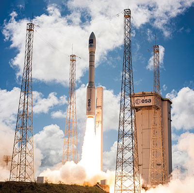
A JAVAD OEM GNSS board is at the heart of the navigation system of the Vega space vehicle developed by the European Space Agency to launch small satellites into low Earth orbit. It provides great flexibility of mission at an affordable cost and represents the European solution for space accessibility. (Photo: Avio, Italy)
JAVAD Board Guides ESA Vega Mission
AJAVAD OEM GNSS board is at the heart of the navigation system of the Vega space vehicle developed by the European Space Agency (ESA). ESA developed Vega to launch small satellites into low Earth orbit. It provides great flexibility of mission at an affordable cost and represents the European solution for space accessibility.
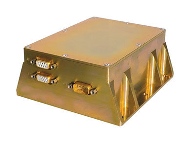
The JAVAD OEM GNSS board is embedded in the gle/RGU/G2T/HDA/MB1 for space missions. (Photo: GreenLake Engineering)
The JAVAD OEM GNSS board is embedded in the gle/RGU/G2T/HDA/MB1 — a cost-effective, high-performance, compact and rugged GNSS receiver specifically designed and environmentally qualified. Installed on the upper stage of the VEGA launcher, it allows accurate trajectory verification during the entire flight mission.
ESA’s initial request was for a GNSS unit built with commercial off-the-shelf components, thus maintaining low costs, but which could still operate in the extreme vibration and shock conditions typical of a space launcher. After an initial feasibility analysis, GreenLake Engineering — a subsidiary of Instrumentation Devices — developed the unit mechanically and electronically to satisfy ESA technical specifications. Its biggest challenge was to pass ESA’s extensive qualification and quality process.
For many years, Instrumentation Devices (based in Como, Italy) and JAVAD GNSS have been partners. Instrumentation Devices sub-contracted for the Vega project with Avio (based in Colleferro, near Rome), which is the prime contractor with ESA. Avio is an international group that designs and produces space launchers and both liquid and solid propulsion systems for space transportation.
ESA supervised the project and is responsible for all activities relating to flight safety and qualification of the equipment installed on board. JAVAD GNSS supported GreenLake Engineering with the integration and low-level configuration of the OEM board for this challenging application.
A Massey Ferguson tractor guided by a NovAtel GNSS OEM receiver. (Photo: Hexagon | NovAtel)
GNSS Makers Share Insights
OEMs Discuss Their Boards, Markets and Company Growth
Five prominent GNSS original equipment manufacturers discuss their current products and future markets.
How do you define OEM?
While all six manufacturers agree on the general definition of OEM given above, they focus on different aspects. OEM customers of JAVAD GNSS “require reliable, accurate and stable high precision measurements for positioning and timing,” Hunter said.
The performance of OEM products from Hexagon | NovAtel reflects on its customers and itself, Gerein said. “Our OEM receiver cards are selected, valued and relied upon as the core positioning elements in many applications across vertical markets. We offer full rebranding options with custom logos, colors and industrial designs to seamlessly integrate our technology into their offerings.”
At Trimble, OEM customers “combine Trimble’s GNSS technology with their domain expertise to deliver solutions to the end customer,” Norse said.
For Hemisphere GNSS, OEM clients can range “from a tinker/maker hobbyist working with GNSS, to a large multinational organization designing navigation solutions for global clients,” Burnell said, but the company looks at all of them “in the same light.” Additionally, “Some OEM clients have all the tools they need already built into the Hemisphere products, while others come to us looking for advanced or custom features to help set their products apart in the market.”
Septentrio has a worldwide support team that assists its OEM clients “in all the stages of their integration process, from validation to product release,” Freulon said.
What distinguishes your latest generation of OEM receiver boards from previous ones?
Septentrio’s most recent OEM receiver boards integrate the latest Septentrio GNSS and INS technology and algorithms. AsteRx-m3 OEM receiver boards use all GNSS constellations, can track all available satellites, and can be used as a base station to deliver RTK corrections or as a rover with a single or dual antenna.
Improvements include lower power consumption, increased security with secure boot, and greater resilience with anti-jamming and anti-spoofing. Its new receiver boards, Freulon said, “are backward compatible with extended capabilities of the latest GNSS signals and several variants of the inertial navigation system.” Upcoming software releases will include Galileo’s free High Accuracy Service (HAS) as well as OSNMA, the latest anti-spoofing mechanism.
Trimble’s latest generation of OEM GNSS boards are based on Trimble Maxwell 7 technology, which features the company’s seventh-generation baseband GNSS ASIC (application-specific integrated circuit). Trimble designed the Maxwell family of products to maximize the quality of observables derived from available signals transmitted from all GNSS constellations as well as satellite-based augmentation systems, Norse explained. This results in stronger signals, greater availability, reduced power consumption, advanced multipath mitigation and protection against spoofing.
The boards also run Trimble’s ProPoint positioning engine, which improves performance in challenging environments such as tunnels, urban canyons and tree canopies and provides continuous RTK using a base station or Trimble RTX correction services delivered via cellular or satellite connections.
JAVAD GNSS’ latest OEM products are “more cost effective” and integrate an IMU with an 874-channel multi-GNSS band module with up to 200Hz positioning and data output. “All are still proudly made in the United States,” Hunter said.
NovAtel’s OEM7 receiver boards feature added options for interference robustness and situational awareness “to help protect the user’s GNSS signals from an increasingly crowded RF spectrum and growing jamming and spoofing threats,” Gerein said. The company enhanced the sensor fusion capabilities with SPAN GNSS+INS technology, enabling a deeply coupled integration with IMUs that strengthens positioning through GNSS interruptions and allows the rapid reacquisition of signals post-outages. The boards are compatible with PPP TerraStar Correction Services “for precise positioning anywhere in the world.”
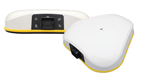
Hemisphere GNSS’ Phantom and Vega series of OEM board products can track all L-band GNSS signals, enabling the company’s OEM clients to upgrade the capabilities of their integrations and “tap into the performance of multi-GNSS, multi-frequency RTK and Atlas PPP solutions,” Burnell said.
The boards consume less power than the previous generation and introduce Hemisphere’s Cygnus automatic interference mitigation technology, which monitors the GNSS signal bands for interference and automatically deploys filters “with no need for integrators or users to understand signal theory,” Burnell explained. Cygnus, which turns off the filters when the interference fades away, is “automatic interference mitigation for the masses.”
What are your markets for your GNSS OEM receiver boards? Which ones are growing the most?
NovAtel said its receiver cards are highly configurable and integrate easily across a wide range of markets, including survey, mobile mapping, agriculture, defense, marine and autonomous platforms for both on- and off-road applications.
In particular, the company’s OEM7 cards “uniquely support the defense market and their requirements for increased protection against jamming and spoofing in mission-critical applications.” The cards also “meet the positioning availability and increasingly rigid product quality standards required in agriculture, automotive and autonomous system markets.”
Trimble lists precision agriculture, construction, mining, forestry, autonomous vehicles, port automation, distribution centers and mobile mapping among the uses of its GNSS OEM receiver boards. “We are seeing growth in markets where reliable, robust and high-precision positioning is required for a solution such as autonomous platforms,” Norse said.
Septentrio reports growing demand for its mosaic GNSS modules “due to their small footprint and impressive performance.” OEM boards, Freulon said, “remain very popular for applications where a quick integration is needed or where ultimate performance is expected.”
However, the most important markets for its OEM boards remain “UAV, together with industrial-grade automations in agriculture, construction or logistics.”
Septentrio sees an increase in “the number of positioning and mapping systems that require the ultimate performance of our receivers, especially when combined with other sensors,” Freulon said. In particular, he cites the performance of its single- and dual-antenna AsteRx-m3 receiver boards and of the AsteRx3i INS boards, which “provide a solution which combines industrial-grade IMU and GNSS all on a single OEM board, greatly simplifying the integration process in systems where both positioning and orientation are needed.”
Hemisphere GNSS, which has a significant OEM presence in the agriculture, marine, survey and GIS markets, reports seeing growth in several markets. “We have seen significant growth in all aspects of autonomous integrations, from ground vehicles for on-road or off-road, to in-flight applications with UAVs, to maritime applications focusing on dynamic positioning in both nearshore and offshore environments,” Burnell said. “There is a recognition that using precision navigation equipment benefits everyone and protects our environment through efficiencies of operation, either in resource management or by improved operational capacity.”
JAVAD GNSS lists maritime positioning and docking, timing, launch vehicle positioning and range safety, autonomous vehicle testing, in orbit positioning and drone guidance among the markets for its OEM receiver boards, with space-related applications the fastest growing market.
OEM7700. (Photo: Hemisphere GNSS)
Briefly describe one of your GNSS OEM receiver boards.
The OEM7700 receiver card from NovAtel is used in agricultural auto-steering applications. “The OEM7700 can receive all GNSS constellations across all frequencies, enabling a highly available position,” Gerein said. “When combined with TerraStar corrections and our SPAN GNSS+INS technology for sensor fusion applications, the OEM7700 ensures highly precise positioning scalable from meter- to centimeter-level accuracy.”
OEM7700 receiver boards help the company’s agriculture customers “solve the positioning challenge of repeatable pass-to-pass accuracy for auto-steering,” Gerein said. Plus, the card meets their strict environmental requirements for agriculture vehicles.
Photo: iXblue
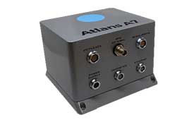
Septentrio’s OEM client iXblue uses the company’s AsteRx OEM boards inside its Atlans A7 positioning and orientation system. “Atlans A7 was developed in close cooperation with Septentrio and is designed to provide continuous and accurate positioning in urban environments,” Freulon said.
Atlans A7 combines iXblue’s inertial navigation system (INS), which is based on a fiber-optic gyroscope (FOG), with Septentrio’s multi-frequency GNSS receiver technologies. To develop this INS-GNSS mobile mapping solution, experts from iXblue and Septentrio worked closely with the aim to develop a smart coupling method that combines the advantages of the two companies’ technologies. The same smart coupling technique is also applied in the post-processing software for an optimal result. The main advantage of Atlans A7 is to maintain a high heading precision in any circumstance, which “allows precise georeferencing for both land and air applications and drastically limits the drift during GNSS outages,” Freulon said.
AX940. (Photo: Trimble)
At Trimble, Norse cites the case of an agribusiness company that wanted to make its robotic tractors able to drive autonomously, requiring centimeter-level positioning and orientation at high update rates in challenging environments. The company chose the Trimble AX940i because of its “combination of GNSS and inertial technology in an easy-to-install smart antenna.” The Trimble ProPoint engine tightly couples the onboard IMU sensor data with the GNSS observations to provide up to 100-Hz outputs utilizing the NMEA-2000 standard or other interfaces. Additionally, Trimble VRS Now service provides instant access to RTK corrections and an operator can use the built-in Wi-Fi to configure and monitor the receiver from nearby.
The HydroBoard II flotation platform contains the RiverSurveyor M9 acoustic device, which measures the flow rates of rivers, streams and irrigation canals. (Image: Hemisphere GNSS)
Hemisphere GNSS’ Phantom 34 RTK receiver and antenna is employed by SonTek in its RiverSurveyor M9 product used by water districts and the U.S. Geological Survey to help monitor and manage water resources. The M9 is one in a series of SonTek products focused on determining flow rates for rivers, streams and irrigation canals. It consists of a small flotation platform with an acoustic doppler current profiler that measures the flow rate of the water column underneath it, a data telemetry system, and the Phantom 34 RTK to pinpoint the data collected.
The platform is floated from shore to shore across a channel using a tether, measuring along the way. “Using RTK simplifies collecting measurements as the survey will have continuous velocity profile measurements the entire way across the waterway,” Burnell said.
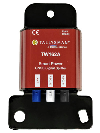
Tallysman Wireless Inc. has added the TW162A automotive-grade smart power GNSS signal splitter to its line of GNSS accessories.
The Tallysman TW162A signal splitter supports the full GNSS spectrum: GPS/QZSS-L1/L2/L5, QZSS-L6, GLONASS-G1/G2/G3, Galileo-E1/E5a/E5b/E6, BeiDou-B1/B2/B2a/B3, and L-band correction service frequency band.
Vehicle rooftop antenna space is often at a premium, and mission applications often require more than one GNSS receiver. The TW162A supports this use case where one GNSS antenna provides the signal to two GNSS receivers.
It also offers key fail-over and fault-identification features.
First, the splitter accepts power from all attached GNSS receivers; if one receiver fails, the next attached receiver automatically provides power to the splitter and antenna.
Second, if the antenna fails and does not draw current, all connected receivers will sense a current draw lower than 1 mA, indicating an antenna fault.
The TW162A offers high performance in terms of noise figure, isolation and linearity. TW162A is built with Automotive Electronics Council AEC-Q100 certified components, ensuring a wide operational temperature range and a long service life. It has been rigorously tested and is packaged in a durable, compact and lightweight aluminum housing.
The TW162A is available with three Z or A+B+C FAKRA connectors.
The GP-L1-32-T-MNT GPS timing antenna with mount included, RHCP polarized, 1.571 to 1.61 GHz. (Photo: RadioWaves)
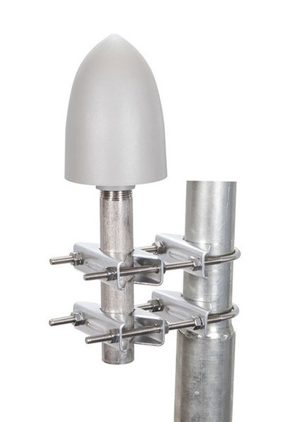
RadioWaves, an Infinite Electronics brand and a manufacturer of high-quality microwave antennas and accessories, has released a new series of GPS/GNSS timing antennas that cover L1 and L5 GPS bands.
The new series of GPS/GNSS timing antennas provide axial ratio and higher accuracy for the reception of satellite timing signals and reference frequencies for enhanced phase synchronization in precision network deployments.
The high gain, low noise figure of 2 dB and high out-of-band rejection provided by these antennas allows for the use of longer and cost-effective cables for easy and flexible installs. They also feature a VSWR less than 1.8:1 and are compatible with several existing mounting brackets. In addition, thee fully ruggedized, weather-sealed antennas are IP67 compliant for use in outdoor and marine environments.
The antennas come equipped with built-in surge protection and support a wide range of GNSS including GPS, GLONASS, BeiDou and Galileo, as well as Iridium. Increased position accuracy in densely populated urban areas, flexible installation, and improved system security make RadioWaves’ latest antenna offering a valuable system component, the company said.
Models include
GP-L1-L5-40-N, an L1+L5 GPS timing antenna, 1.166 to 1.218 GHz and 1.559 to 1.606 GHz
GP-L1-32-T, a L1 GPS timing antenna, RHCP polarized, 1.574 to 1.61 GHz
GP-L1-32-T-MNT, an L1 GPS timing antenna with mount included, RHCP Polarized, 1.571 to 1.61 GHz.
A Nov. 17 webinar will focus on ways to deter attacks on and interference with GPS satellites and signals. The webinar takes place 2:30-3:30 p.m. EST; register for free.
Rep. John Garamendi (D-CA) will provide opening remarks for the webinar, which is co- sponsored by Domestic Preparedness Journal and the Resilient Navigation and Timing Foundation. Garamendi is the chair of the House Armed Services Readiness Subcommittee and has long been concerned about the vulnerability of America’s GPS.
“America’s over-reliance on GPS makes it a high priority target for a wide range of bad actors,” said Dana A. Goward, president of the Resilient Navigation and Timing Foundation and one of the webinar moderators. “And, since other nations, such as China, Russia and Iran, have terrestrial systems they can use when space is not available, the U.S. is at a strategic disadvantage.”
This “technology resilience gap” is one of several dangers that could lead to armed conflict that webinar panelist George Beebe discusses in his book The Russia Trap. His concern is that having such a pronounced relative weakness can invite meddling and exploitation by adversaries. Even if done on a small scale, this could lead to a series of escalating responses ending in an unintended, much more serious conflict that neither party wants.
Beebe is vice president and director of studies at the Center for the National Interest. He spent more than two decades in government service as an intelligence analyst, diplomat and policy advisor, including service as director of the CIA’s Russia analysis and as special advisor to Vice President Dick Cheney for Russia/Eurasia and Intelligence Programs.
Eliminating the gap between the United States and its adversaries is key to protecting GPS and the nation, according to webinar panelist Greg Winfree, director of the Texas A&M Transportation Institute. Winfree previously served as an assistant secretary for the U.S. Department of Transportation. While acknowledging there is no single answer, he has asserted that providing at least one alternative system will go a long way toward “getting the bullseye off GPS.”
The third webinar panelist, Scott Pace, has supported Winfree’s approach. Pace is the director of George Washington University’s Space Policy Institute and former executive director of the National Space Council. He has commented that having an alternative to GPS will contribute to national security and improve global stability. It will “lower the pressure on us to escalate and respond” should GPS satellites be damaged or services disrupted.