ViaLite GPS Link: Blue OEM module and rack chassis card hardware formats shown. (Photos: ViaLite)
ViaLite is supplying Raytheon Technologies with its GPS over Fiber Extension Kit for Microchip GPS servers. The kit provides mission-critical GPS timing and synchronization for systems requiring extremely accurate clock signals.
Standard transmission distances for the extension kit can be up to 10 km, while solutions are available for distances as long as 50 km.
“The ViaLite kit was chosen for its unique performance with Microsemi’s S650 timing server, along with our best-in-class quality, reliability and support,” said Craig Somach, ViaLite director of Sales North America.
The ViaLite GPS link is designed to provide a remote GPS/GNSS signal or derived timing reference to equipment located where no signal is available, such as inside buildings or tunnels. By using optical fiber instead of traditional coaxial cable, extreme distances are possible with no radio frequency loss and zero introduction of noise.
Saab, the Swedish defense and security company, and Maxar recently demonstrated a solution to GNSS-denied navigation by integrating Maxar’s 3D Data and Precision 3D Registration (P3DR) technology into the fighter jet software for the Swedish Gripen E fighter jet.
Saab develops and manufactures the fighter jet for Sweden and other countries.
A camera on the jet captures a livestream of its flight path. Maxar’s P3DR compares that incoming livestream to the Maxar 3D Surface Model of the area stored on the jet. By matching scenes in the livestream to the 3D data in real time, P3DR can determine the jet’s precise location, enabling the pilot to navigate and carry out the mission without GPS.
Maxar 3D Surface Model, immersive 3D data with superior accuracy and global coverage, offers a highly accurate representation of Earth. The data is produced with unique automated technology, delivered rapidly and with high precision. It is based on Maxar’s high-resolution, unclassified commercial satellite imagery, without the need for ground control points. Maxar’s 3D Surface Model product is a key input to the company’s Globe in 3D, a worldwide foundation of 3D data with resolution of 50 cm or better and 3 m accuracy in all dimensions.
The chart across the top of the video indicates the accuracy of the P3DR matching of the livestream video to the Maxar 3D Surface Model. When the camera encounters clouds, it lowers the accuracy of P3DR’s match; however, as long as there is some view of the ground, the accuracy is relatively high.
Maxar’s P3DR is a standalone software solution that automatically geo-registers imagery from any source to Maxar 3D reference data. This real-time capability enables navigation in a GPS-denied environment, safeguarding against signal jammers in an anti-access area denial (A2AD) environment.
Saab put the GPS-denied navigation technique to the test with a Gripen flight demonstration over Sweden. The GIF below demonstrates how P3DR closely overlays the livestream image on the Maxar 3D Surface Model, allowing the pilot to understand where they are on the map.
During the flight demonstration, the Gripen’s GPS receiver was on to monitor the accuracy of the results. The GPS receiver verified that the demonstration’s results were accurate.
The Gripen E jet fighter built by Saab. (Photo: Saab)
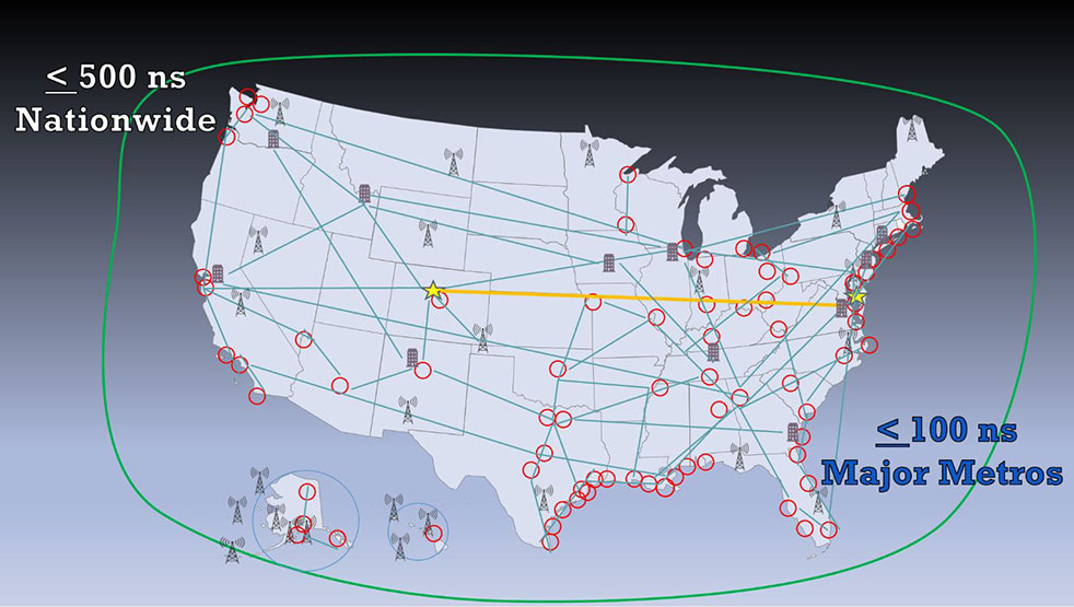
A National Resilient Timing Architecture should include delivery by fiber and RF along with space-based, according to the RNT Foundation. (Image: RNT Foundation)
The Resilient Navigation and Timing (RNT) Foundation has published a white paper proposing attributes for a government Request for Proposal (RFP) to acquire timing services.
Timing services, most of which are now sourced directly or indirectly from GPS, are essential for myriads of network, transportation, financial, industrial, and other applications. The National Timing Resilience and Security Act of 2018 (NTRSA) requires establishment of one or more systems to serve as alternatives and back up GPS timing.
The RNT Foundation’s October 2020 white paper discusses how a national timing architecture fulfilling the requirements of NTRSA could be established relatively easily and inexpensively. It proposes that, rather than building its own system, the government contract for services with commercial providers.
The new white paper outlines some of the requirements and evaluation criteria the government might use when acquiring timing services.
Goals
The paper postulates that the goal of such a procurement should be to establish a federal timing “backbone.” This would fulfill the requirements of NTRSA, which recognizes that timing is critical for many applications and is also the basis for most electronic positioning and navigation systems.
Establishing this backbone will provide users with an alternative and a safety net for GPS disruptions, and at other times enable more resilient and reliable services. As a backbone, it would provide basic, foundational services upon which others would be able to build. The new services would be expected to:
support a wide variety of public and private applications across the nation
be entirely independent from and have minimal or no common failure modes with GPS and other GNSS
provide multiple and diverse methods of timing delivery
serve both fixed and mobile users.
Regarding this last point, the paper notes that mobile devices must know their location before they can make use of timing signals. Thus, the selected system or combination of systems also will have to provide GPS-independent location information at a basic level to mobile users.
Requirements
Successful proposals, the paper envisions, will need to meet a number of requirements including
serving the entire U.S. land area, airspace, and coastal waters to about 200 miles offshore
enabling all fixed and mobile users to access at least one non-space-based source (to ensure no common failure modes with GPS/ GNSS)
timing accuracy in all locations to within 500 nanoseconds of universal coordinated time (UTC); this accuracy should be within 100 nanoseconds of UTC for the 50 largest metropolitan areas
one or more integrity measures to provide users confidence in system(s) accuracy
a very high rate of continuity and availability, similar to that of navigation beacons for aircraft
a performance monitoring and control system.
Evaluation Criteria
Fortunately for the government, numerous systems and companies are already able to provide the needed services. Deciding which to select will likely be a significant effort. Some of the evaluation criteria suggested by the RNT Foundation white paper are:
Annual Cost – While cost will not be the only consideration in this acquisition, the government always has a responsibility to taxpayers to weigh it as an important factor.
Infrastructure Required Per Unit of Coverage Area – This has been cited by the Department of Transportation as a very important consideration. Not only does the amount of infrastructure affect cost, but it also has implications for environmental and community impacts.
Spectrum – Signal disruption by in-band and out-of-band transmissions has been a significant issue for GPS. New PNT wireless and radio-frequency services should pose as few spectrum concerns as possible. Spectrum band reservations, licenses, pre-allocated bands, other bands and adjacent band uses will all be given consideration.
Penetration – While the government may not list this as a requirement, the ability of a service to reach underwater, underground and indoor locations will likely be desirable and part of proposal evaluation.
Resilience – The vulnerability of GPS signals to disruption will undoubtedly make the resilience of potential backup and complementary systems a major issue. The RNT Foundation paper discusses two kinds of resilience – operational and recovery.
Operational resilience is defined as “the ability of a system, combination of systems, or service to resist disruption (e.g.: jamming, spoofing, physical damage negatively impacting service).” One measure of resilience might be the energy needed to disrupt signals.
Recovery resilience is described as “The speed and ease with which a service can return to normal operation” after a disruption.
Cybersecurity – Similarly, cybersecurity is seen as having two components. The first is network security, defined as the degree to which systems are isolated from or connected to networks. Second is signal security, and is how well signals can be protected from infiltration and imitation.
Endorsements for GPS Alternative Timing
Since the “National Resilient Timing Architecture” white paper was issued in 2020, calls for GPS alternatives have intensified, and the white paper itself has received an important endorsement.
On May 7, the telecommunications industry standards group Alliance for Telecommunications Industry Solutions (ATIS) vigorously supported federal funding for GPS alternatives. In letters to leaders in both houses of Congress, ATIS cited “the urgent need for funding the deployment and adoption of Alternative Positioning, Navigation, and Timing (PNT) Systems in U.S. critical infrastructure, including the U.S. telecom industry.”
The need for federal support for timing and positioning backups for GPS was also supported by a two-year old study released by RAND Corporation in May. While the paper went to great lengths to argue against a duplicate GPS-like capability (something no one has supported to the best of our knowledge), it quietly suggested federal support for both a national timing system and location services to serve E-911 systems.
Numerous recent media releases from U.S. Space Force have revealed serious military threats to GPS and other space-based systems. A variety of killer-satellites, lasers and other weapons have turned space from a sanctuary into a potential battle ground. While not specifically calling for alternatives to GPS, the Space Force announcements have made it clear the nation needs to “get the bullseye off GPS.” Establishing at least one terrestrial alternative system similar to those operated by our adversaries will make U.S. satellites and signals much less attractive targets, according to Greg Winfree, former assistant secretary at the U.S. Department of Transportation.
Federal Funding Needed
Federal funding for improving national timing was specifically supported by a group of CEOs and senior executives from major telecom companies. Acting as the National Security Telecommunications Advisory Committee (NSTAC), the group’s May report to President Biden discussed GPS vulnerabilities and threats, and urged establishment of a capability
“…similar to that reflected in the Resilient Navigation and Timing Foundation’s paper entitled A Resilient National Timing Architecture. Further, to enhance the ability of commercial entities to afford leveraging this architecture, the Administration should appropriate sufficient funds to lay the foundation for creating this timing architecture, with the Federal Government being the first customer for what will ultimately become a resilient, interconnected network for PNT delivery.”
Federal funding support is necessary, according to NSTAC, because free GPS services greatly suppress market demand for alternatives.
A notice of award was posted Oct. 11 by the European Union for seven contracts to six different companies for demonstration of non-GNSS positioning, navigation, or timing solutions.
The awardees are OPNT BV from the Netherlands; Seven Solutions SL from Spain; SPCTime of France; GMV Aerospace of Spain; Satelles Inc. of the United states; and Locata Corporation of Australia.
Locata received two separate contract awards: one to demonstrate delivery of time, and the other for positioning.
According to the EU project officer, Ignacio Alcantrailla-Medina, some of the awardees will demonstrate delivery of time, some positioning, and some both. Locata received separate awards because the company provided separate responses for timing and positioning.
Eleven different companies responded to the tender, according to the announcement. No information was provided on the unsuccessful bidders.
The EU tender for this project was announced in October 2020. The stated goal of the project is to better understand available non-GNSS PNT technologies. The intent is to identify potential backups for GNSS during an outage. All offered technologies were required to be able to operate independently from and have “no common points of failure with” GNSS.
Alcantrailla-Medina says the demonstration project is expected to last seven and a half months. As part of this, a public event will be held at the EU’s Joint Research Center in Ispra, Italy, in March or April, 2022. This will be followed by a consolidated report on the project in May or June.
This consolidated report will be used in the next edition of the European Radionavigation Plan due out next fall, according to Alcantrailla-Medina.
Companies that did not respond to the EU’s tender or were not selected for a contract can still have information about their products and services included in the consolidated report, says Alcantrailla-Medina. Now that all contracts for the demonstrations have been awarded, he is open to receiving the information and can be contacted at:
Ignacio.ALCANTARILLA-MEDINA
European Commission
DG Defence Industry and Space
Unit C2 – Satellite Navigation
Avenue d’Auderghem 45, (BREY 7/297)
B-1049 Brussels/Belgium
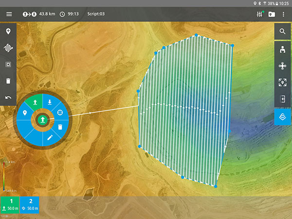
The mdCockpit app from Microdrones was designed for professional drone users to make it easy to plan, monitor, change and control flights from an Android tablet.
The latest updates — in mdCockpit 2021.3 — include new features that improve flight safety and give more options for surveying in an aim to deliver a premier solution for planning, monitoring, adjusting, analyzing and controlling professional drone flight missions right from a tablet. Robert Chrismon, the marketing manager, and Maude Morin, Software Product Owner discuss the updates in the video below.
Key updates for mdCockpit version 2021.3 are in the Flight Editor, Flight Data and Drone Configuration components of the app.
FLIGHT EDITOR
New layers section in Mission Dashboard
KML as a background layer
Optimized entry point on corridors
FLIGHT DATA
Displays last position of the drone
Drop renamed to Descent in Quick Height Change dialog
Telemetry alerts
DRONE CONFIGURATION
New maintenance program fields in drone config
Reminder of the next inspection or service
Read only homing height
Drone pilots can download mdCockpit onto their Android table through the Google Play store.
TomTom integrates Vaisala’s environmental data capabilities into its Hazard Warnings service to deliver time-critical alerts for road weather hazards
Vaisala — a global leader in weather, environmental and industrial measurement — will bring its accurate insights and actionable road weather data to the TomTom Hazard Warnings service.
TomTom Hazard Warnings creates time-critical signals that alert drivers and automated vehicles to safety-critical incidents as they happen. These incidents include traffic, weather and road hazards.
“More than every fifth traffic accident is a result of inclement weather-related impacts, yet drivers often don’t receive real-time information about weather or driving conditions from their in-vehicle technology — even in new vehicle models,” said Petri Marjava, head of Automotive at Vaisala. “While TomTom has utilized our atmospheric weather data for years, our new arrangement equips its Hazard Warnings service with must-have predictive road weather information. Road weather data takes in-vehicle weather services to the next level by helping drivers stay safe while conveniently optimizing route and travel times in all weather conditions.”
TomTom Hazard Warnings uses Vaisala’s data to deliver early warnings related to weather hazards, such as slippery roads, reduced visibility and strong winds. This data enables better route planning and notifies drivers to prepare and adjust for driving in poor conditions.
In addition to general weather conditions and detailed point forecasts, Vaisala is now providing TomTom Hazard Warnings with road surface measurements and driving conditions forecasts.
The road weather data Vaisala delivers covers continent-wide road networks across the United States and Europe to enhance driver safety, efficiency and convenience, with other geographical regions to follow.
The ionosphere is shown in purple and not-to-scale in this image. (Image: NASA’s Goddard Space Flight Center/Duberstein)
Researchers have developed a new mathematical model to more accurately capture how ionospheric scintillation interferes with GNSS signals, reports EOS.
The new model uses a Markov chain. The model’s parameters were drawn from data on actual signal disruptions caused by ionospheric scintillation above Hong Kong on March 2, 2014. The researchers compared its predictions with real-world data and found it accurately emulated the timing and duration of the actual signal disruptions and did so more accurately than an earlier model that did not use a Markov chain approach.
Citation: “Markov Chain-Based Stochastic Modeling of Deep Signal Fading: Availability Assessment of Dual-Frequency GNSS-Based Aviation Under Ionospheric Scintillation” by Andrew K. Sun, Hyeyeon Chang, Sam Pullen, Hyosub Kil, Jiwon Seo, Y. Jade Morton and Jiyun Lee, Published in Space Weather, June 24, 2021. https://doi.org/10.1029/2020SW002655
The team’s findings also suggest that dual-frequency GNSS signals can significantly counteract the disruptive effects of strong scintillation, specifically for aircraft navigation.
In the future, this new modeling approach could be extended to improve understanding of other effects of ionospheric scintillation on GNSS signals, as well as their effects at other latitudes.
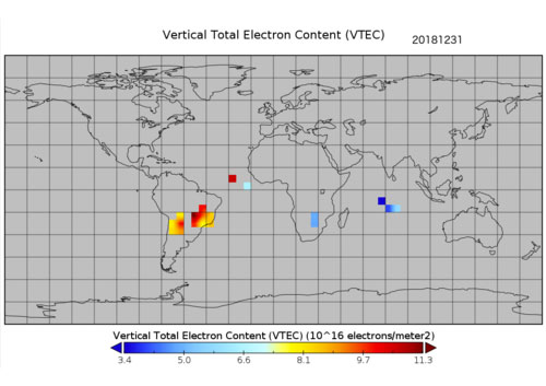
A new data source to help scientists better understand the ionosphere and its potential impact on communications and positioning, navigation and timing (PNT) is now available to the public.
The data, which was collected by sensors on GPS satellites in 2018, was released through a collaborative effort by Los Alamos National Laboratory and the National Oceanic and Atmospheric Administration (NOAA).
“Radio signals from satellite or ground-based transmitters can travel through the ionosphere or bounce off of it, so ionospheric conditions have the potential to disrupt communications depending on the density of electrons,” said Erin Lay, a remote-sensing scientist at Los Alamos who was a technical lead on the project. “This new set of data will help us better model and predict the behavior of the ionosphere and possibly improve the reliability of our communications and positioning, navigation, and timing services, which are critical for both everyday life and national security.”
The ionosphere is the boundary between Earth’s atmosphere and space, stretching 40 to 250 miles above Earth’s surface. It is composed of tenuous atmosphere and charged particles (ions and electrons) that interact with traversing radio waves. The behavior of the ionosphere reacts to weather on Earth, such as thunderstorms, wind, and hurricanes, as well as space weather created by solar winds impacting Earth’s magnetic field.
“NOAA’s Space Weather Prediction Center (SWPC) serves a huge customer base interested in space weather effects on communications and GPS-reliant technologies,” said Bill Murtagh, program coordinator at SWPC. “We expect access to these Los Alamos data sets to improve the development, validation, and testing of models used at SWPC for characterizing and forecasting ionospheric disturbances.”
Preview graphic. (Image: NOAA)
The new data comes from unique measurements of lightning events, each of which produces a flash of radio waves that gets dispersed through the ionosphere before it is detected on satellite receivers. Each measured flash provides a snapshot of the ionospheric conditions at that instant, and many lightning measurements accumulated over time provide a unique view of ionospheric weather. This is the first-ever global set of ionospheric electron density data to use a naturally occurring source phenomena.
Before this release, the data available to feed ionosphere models was primarily from arrays of ground-based receivers, which are limited because they only monitor fixed locations. According to Lay, “the new data is gathered from lightning that happens all over the world and will give scientists the opportunity to study the ionosphere in ways previously not possible.”
The release of underutilized data sets was a priority established in the 2019 National Space Weather Strategy and Action Plan. Los Alamos processed the data from its radio-frequency sensors that are onboard GPS satellites and used for nuclear treaty monitoring, and then worked with a government interagency group, called the Space Weather Operations, Research and Mitigation (SWORM), to facilitate public release.
NOAA’s National Centers for Environmental Information will host the data on existing sites that serve terrestrial weather and space weather resources.
The ionosphere is shown in purple and not-to-scale in this image. (Image: NASA’s Goddard Space Flight Center/Duberstein)
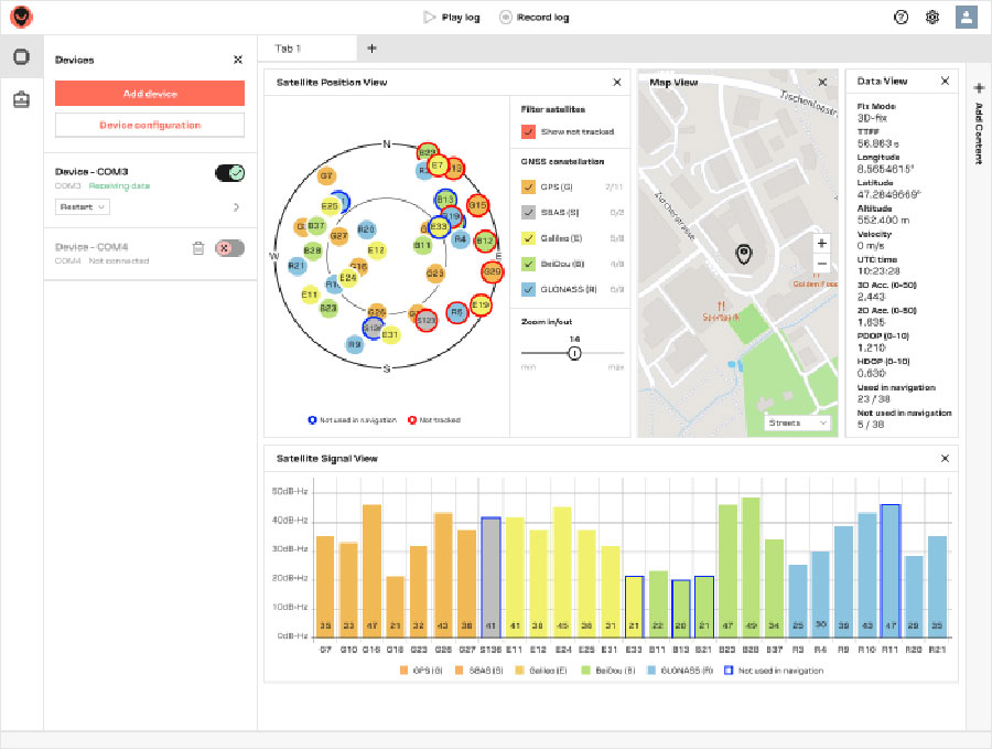
U‑blox has launched its new GNSS evaluation software, u-center 2. The software, which runs on Microsoft Windows, offers anyone working with 10th-generation (M10) u‑blox GNSS technology a highly intuitive interface to configure GNSS products, evaluate their performance, improve the quality of their software, and experience the performance boost achieved using GNSS-related services.
U-center 2 is the successor to the u-center GNSS evaluation software, which has been used by design engineers for almost two decades to develop GNSS receiver applications. Compatible with u‑blox M10 GNSS technology, u-center 2 is designed to offer improved performance over its predecessor, as well as new features that simplify configuration, evaluation and software development of GNSS-based solutions.
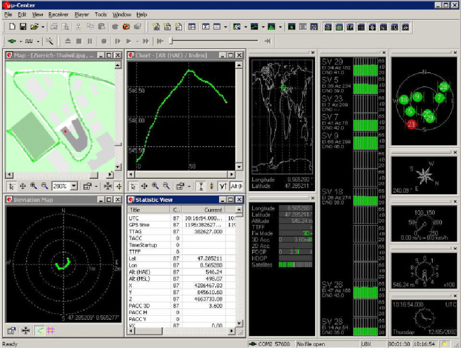
Screenshot: U-blox
U-center 2 provides personalized workspaces with adaptive window elements offering a choice of views to observe static and dynamic behavior of the connected GNSS receiver. The built-in log player, which accepts log files from the previous version of the software, features easy message- and time-based navigation and lets users set the playback speed, making development of end products more efficient. Automatic updates ensure that the software includes the latest features with minimal user effort.
U-center 2 simplifies the evaluation of GNSS-related location services such as AssistNow, through which GNSS receivers gain access to GNSS aiding data, enhancing startup performance, and saving power.
Predecessor u‑center will continue to be the go-to solution for GNSS solutions based on earlier technology platforms.
“We are confident that users will immediately recognize how easy u-center 2 makes it to set up and evaluate the latest generations of our GNSS chips and modules,” said Bernd Heidtmann, product manager, Product Strategy for Standard Precision GNSS, u‑blox. “With its fresh and minimalist user interface, the upcoming quick product configuration designed for key use cases, and optimized data logging, u-center 2 will raise the benchmark for GNSS evaluation tools in terms of performance and user experience.”
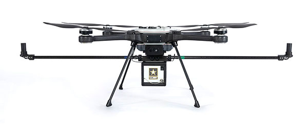
RedTail Lidar Systems has delivered six lidar systems to the 707th Ordnance Company stationed at Joint Base Lewis-McChord. The systems will provide explosive ordnance disposal (EOD) technicians an opportunity to assess how lidar can be used to enhance their operations.
The RedTail Lidar Systems RTL-450 was integrated onto the Teledyne FLIR SkyRaider unmanned aerial system (UAS) to address a broad range of the EOD community’s 3D mapping needs. Captain William R. Hartman, the commander of the 707th EOD Company, stated that the highlight of the testing was using the lidar system to map terrain.
The RTL-450 also can be used to calculate crater volumes from improvised explosive device (IED) blasts, perform route planning for unmanned ground vehicles, aid in mission planning, and conduct surveillance. The 3D point clouds generated allow operating areas to be viewed from any perspective using the rotation and zoom capabilities provided within the viewer software.
The underlying lidar technology used in the RTL-450 was licensed from the Army Research Laboratory (ARL). The micro-electromechanical (MEMS) mirror-based design provides enhanced 3D imagery suitable for applications where artificial intelligence and machine learning (AI/ML) algorithms can be used for target detection and classification, because of the high point density of the point clouds.
The system can operate in either a raster scan mode for surveillance missions or a side-to-side line scan mode for area mapping while the UAS is flying. The intuitive command and control, high brightness display integrated into the ground control station (GCS), and real-time 3D map generation allows operators to begin mission planning and analysis even before the mapping or surveillance missions are completed.
“Delivering these six lidar systems to EOD technicians for test and evaluation is a significant step forward in using MEMS mirror-based lidar technology to address a broad range of Department of Defense 3D mapping needs,” said said Brad DeRoos, president and CEO of RedTail Lidar Systems. In addition, this delivery represents a true success story in transitioning a technology out of a Department of Defense laboratory and back into the hands of military operators.”
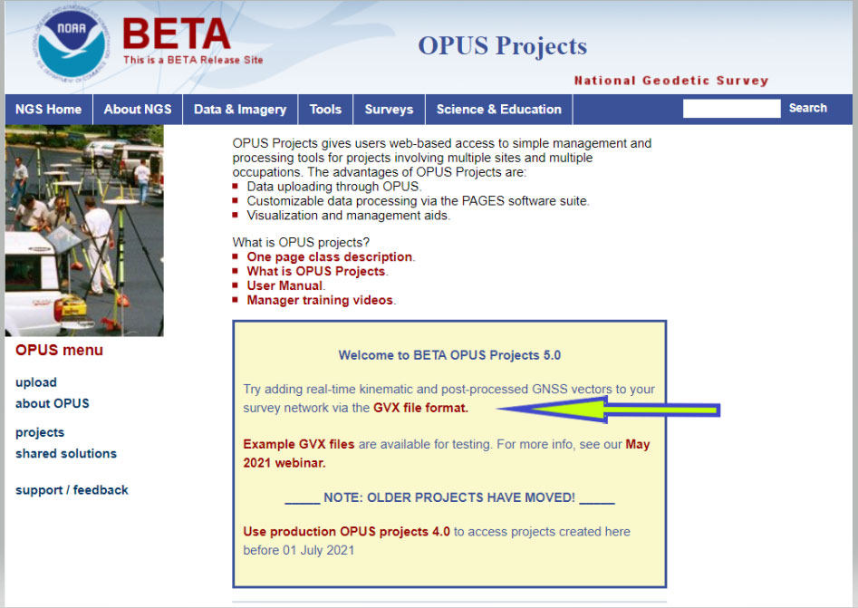
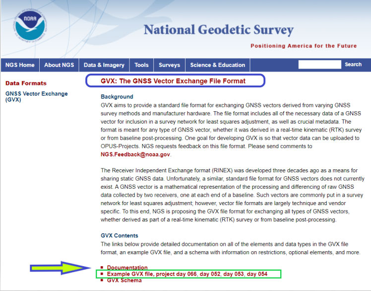
On Sept. 16, the National Geodetic Survey (NGS) released the latest beta version of OPUS, called Beta OPUS Projects 5.0. This version of OPUS now accepts real-time kinematic data and post-processed GNSS vectors from vendor software. See the box titled “Beta OPUS Projects 5.0 Webpage” on the website.
As stated in the announcement, NGS has developed a file format for submitted real-time kinematic (RTK) data and post-processed GNSS vectors from vendor software to NGS. It is denoted as GNSS Vector Exchange Format (GVX). This format enables NGS to incorporate the data into its GNSS processing routines.
This is similar to the original Receiver Independent Exchange Format (RINEX) developed for making post-processing more efficient when combining GNSS data from manufacturers outputting raw GPS data in varying file formats. In my opinion, this is a significant improvement to NGS’s OPUS web utility.
Users can obtain background information about the GVX file format by clicking the link GVX file format. More detailed information about the GVX format can be obtained by clicking on the Documentation link.
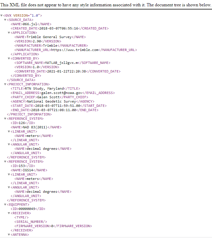
Basically, GVX is a standardized format for exchanging GNSS vectors derived from GNSS survey data using any manufacturer hardware and software results (see the box titled “Excerpt from Documentation of GVX”). NGS designed the format so that it included all of the necessary data (including metadata) of a GNSS vector for incorporation into a survey network for performing a least-squares adjustment.
To this end, this document proposes a new standardized file format known as the GNSS Vector Exchange Format (GVX). GVX aims to provide a standard format for exchanging GNSS vectors derived from varying GNSS survey methods and manufacturer hardware. The file format includes all of the necessary data of a GNSS vector for inclusion in a survey network for least squares adjustment, as well as metadata which describes the vector. The format is meant for any type of GNSS vector, whether it was derived in real-time or from baseline post-processing. GVX has been written in extensible markup language (XML). XML was chosen because it was designed to carry and store data in plain text format, it is easy to expand and/or upgrade to new operating systems, and it can be read by both humans and machines.
A sample GVX file can be obtained by clicking on the link titled “Example of GVX file, project day 066, day 052, day 053, day 054.” As NGS states in the documentation, the output can be read both by humans and machines. What’s important is that it can be read by machines so the information can be incorporated into software programs. GNSS vendors have all the information they need to generate the output file to enable users to import the data into OPUS Project 5.0. Users will have to contact their software providers to determine whether their software routines generate the GVX output files.
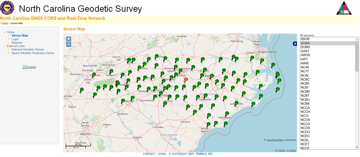
As I previously mentioned, this new option in OPUS Projects 5.0 is a significant improvement because many surveyors use RTK networks to obtain coordinates of marks. It will also facilitate the occupation of benchmarks with GNSS equipment to support the NGS 2022 Transformation tool. North Carolina, my home state, has a real-time network (RTN) that includes 96 GNSS CORS. (See the box titled “NC GNSS CORS and Real-Time Network.”) Currently, the North Carolina GNSS CORS and RTN has 4584 RTN service subscriptions.
I could not find a current list of public RTK networks in the United States, but I did locate a Jan. 7, 2014, GPS World article by Eric Gakstatter that provided a list of public RTK base stations in the country. It’s not up-to-date, but it highlights that, more than seven years ago, more than half of the U.S. states had some kind of public RTK network. I would like to update the table, so I’d appreciate receiving information on the status of any public RTK network. Please feel free to send me an email at [email protected].
California Real Time Network (CRTN) (single baseline). Plate Boundary Observatory. Single baseline.
Colorado
Mesa County (Trimble network) and Plate Boundary Observatory (single baseline).
Florida
Florida Department of Transportation. Leica network.
Idaho
Plate Boundary Observatory (single baseline).
Indiana
Indiana Department of Transportation. Leica network.
Iowa
Iowa Department of Transportation. Leica network.
Kentucky
Kentucky Transportation Cabinet. Trimble network.
Louisiana
Louisiana State University. Trimble network.
Maine
Maine Department of Transportation. Trimble network.
Massachusetts
Massachusetts Department of Transportation. Leica network.
Michigan
Michigan Department of Transportation. Leica network.
Minnesota
Department of Transportation. Trimble network.
Mississippi
University of Southern Mississippi. Trimble network.
Missouri
Missouri Department of Transportation. Trimble network.
Montana
Plate Boundary Observatory (single baseline).
Nevada
Washoe County. Trimble network. Las Vegas Valley Water District. Leica network. Plate Boundary Observatory (single baseline).
New Mexico
Plate Boundary Observatory (single baseline).
New York
New York Department of Transportation. Leica network.
North Carolina
N.C. Department of Environment and Natural Resources. Trimble network. $500 one-time sign-up fee.
Ohio
Ohio Department of Transportation. Trimble network.
Oregon
Oregon Department of Transportation. Leica network. Plate Boundary Observatory (single baseline).
South Carolina
South Carolina Geodetic Survey. Public but charges a usage fee. Trimble network.
Tennessee
Tennessee Department of Transportation. Public but charges a usage fee. Topcon network.
Texas
Texas Department of Transportation. Public but only available to TxDOT employees and TxDOT contractors. Trimble network.
Utah
Utah Automated Geographic Reference Center. Public but charges a usage fee. Trimble network. Plate Boundary Observatory (single baseline).
Vermont
Vermont Geodetic Survey. Trimble network.
Washington
Washington State Reference Network (Seattle Public Utilities). Trimble network. Public but charges a usage fee. Pierce County (Leica Network). Plate Boundary Observatory (single baseline).
West Virginia
West Virginia Department of Transportation. Trimble network.
Wisconsin
Wisconsin Department of Transportation. Trimble network.
Wyoming
Plate Boundary Observatory (single baseline).
Why do I believe that this new option in OPUS Projects 5.0 is so important? Because it facilitates the incorporation of accurate GNSS-derived ellipsoid and orthometric heights into the National Spatial Reference System (NSRS). With the development of improved algorithms, the results of coordinates computed using GNSS CORS/RTNs are more accurate today than ever before. During the last decade, there have been many studies analyzing GNSS data to estimate the accuracy values of coordinates from RTN data.
A study titled “Accuracy of GNSS Observations from Three Real-Time Networks in Maryland, USA” by Daniel Gillins, Jacob Heck, Galen Scott, Kevin Jordan and Ryan Hippenstiel presented at FIG Working Week 2019 in Hanoi, Vietnam, April 22–26, 2019, provided a comparative evaluation on the accuracy of three independent RTNs constructed with differing hardware and software. Their study was based on 486, 5-minute duration GPS + GLONASS network RTK (NRTK) observations. The results indicated that repeat NRTK vectors could be combined to meet 1 cm horizontally and 2 cm vertically (ellipsoid height) accuracies at 95%. confidence. See the box below. It should be noted that the repeat observations should be observed at different times of the day (for instance, separated by > 2–3 hours), as well as, in my opinion, if possible at least more than two different days.
A total of 486, 5-min duration, GPS+GLONASS NRTK observations were collected on nine bench marks distributed over a 4,000 square km area with rovers connected to three different RTNs in Maryland. Each RTN was developed with equipment and software from a different manufacturer, yet all three RTNs performed similarly in terms of accuracy. When differenced with coordinates from a static GNSS survey campaign, the horizontal and vertical RMSE of the NRTK-derived coordinates was 2.3 cm horizontally and 4.5 cm vertically at 95% confidence. Repetitive NRTK vectors on each baseline differed between ± 2.4 cm horizontally and ± 3.4 cm vertically at 95% confidence. As a final accuracy evaluation, hybrid survey networks consisting of repeat NRTK vectors and baseline solutions from post-processing static GPS data collected at RTN base stations and CORSs were adjusted by least squares. Prior to adjustment, the VCV matrices of the vectors were scaled by variance-component estimation. Adjustment of hybrid survey networks with four repeat NRTK vectors per bench mark produced network accuracies at 95% confidence for the adjusted coordinates at all bench marks less than 1 cm horizontally and 2 cm vertically (ellipsoid height).In addition to the benefits of using efficient and accurate NRTK vectors, the hybrid survey network approach makes use of redundant vectors for checking data and avoiding blunders. The approach also provides traceability because the NRTK vectors are tied to an RTN base station which is tied to CORS. Finally, these networks ensure the survey is referenced to the published coordinates of the CORSs which are held as constraints in the adjustment.
Lastly, I would like to remind users that only three months remain until the December 31, 2021, cutoff to submit GPS on Benchmarks data that NGS can guarantee will be analyzed to compute the initial set of 2020.0 Reference Epoch Coordinates (RECs) that will be released with the Modernized NSRS. This initial set of RECs is currently the only set that NGS can guarantee will be used to build the 2022 Transformation Tool. Once the transformation model is finalized, the NAVD 88 – NAPGD 2022 transformation values will be locked in and will not be updated as additional sets of RECs are computed. If you have questions or concerns about this cut-off date, please contact your NGS Regional Geodetic Advisor, or drop NGS a line at [email protected].
Beta OPUS Project 5.0 is a web-based tool that makes it easier to submit data to NGS. I would encourage NSRS users to occupy as many benchmarks with GNSS equipment and submit the data to NGS before the Dec. 31 deadline. Not only will these data help in improving the transformation model, but the marks will be included in the first computation of Reference Epoch Coordinates (RECs). You can obtain information about Reference Epoch Coordinates in NGS’s NOAA Technical Report NOS NGS 67 publication titled “Blueprint for the Modernized NSRS, Part 3: Working in the Modernized NSRS.” A future column will address the different types of coordinates that will be distributed by NGS with the modernized NSRS.
A roundup of recent products in the GNSS and inertial positioning industry from the October 2021 issue of GPS World magazine.
MOBILE
Smartwatch
Provides dual-frequency and topo maps
Photo: Coros
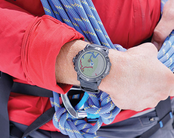
The Vertix 2 GPS “adventure watch” is equipped with a dual-frequency GNSS chipset for high accuracy. It communicates with all global navigation satellite systems simultaneously, and has a battery life of 140 hours while using GPS — otherwise, the battery extends to 60 days. Global offline maps include landscape, topography and hybrid views. The watch includes an Insta360 action camera and has 32 GB of internal storage.
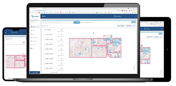
AirFinder helps companies locate, monitor and manage business assets indoors and outdoors. The quickly deployable, massively scalable platform does not require an IT infrastructure or extra components or hardware. Rather than using an internal Wi-Fi system, AirFinder operates on Link Labs’ patented and secure Symphony Link network. Location data from each AirFinder device securely flows to the AirFinder web app or directly to customer databases via extensible APIs, which enable users to monitor assets in real time, analyze asset history, add rules and alerts, establish geofences and more.
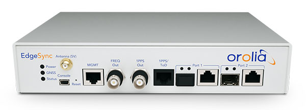
The EdgeSync network timing platform provides NTP and PTP grandmaster and boundary clock functionality for real-time edge applications. High performance, scalability, ease of use and manageability make EdgeSync suitable for data centers, finance, mobile edge computing, enterprise, smart grid, industrial IoT, process control and telecommunications. EdgeSync uses a multi-GNSS receiver (GPS, Galileo, GLONASS, BeiDou and QZSS), PTP and Synchronous Ethernet (SyncE) as input references and generates PTP, SyncE, NTP and timing signals (10 MHz, 1 PPS and time-of-day message) as outputs. It features dual 1-GbE ports for both copper RJ45 and optical network timing connections. EdgeSync also can provide IEEE 1588-2008 (PTP) grandmaster and boundary clock functionality.
CompassOne provides real-time military-grade location, orientation and direction sensing for deployed static and on-the-go assets. It receives all GNSS, ensuring uninterrupted operation. The device can be used both in counter UAV operations and general situations requiring satellite navigation. With a strong focus on durability and ruggedness, CompassOne is suitable for installation and operation in harsh environments. Military-grade connectors and high-end stainless-steel hardware ensure uninterrupted connection and protection from the elements, while the aluminum underside provides exceptional impact resistance and rigidity while keeping overall weight low. CompassOne can operate alone or be integrated with DroneShield’s DroneSentry system.
The Snapdragon 888+ 5G mobile platform is expected to power commercial smartphones from ASUS, Honor, Motorola, vivo and Xiaomi in the second half of this year. Satellite systems supported include all four constellations (GPS, BeiDou, Galileo, GLONASS) with dual-frequency GNSS. Additional systems supported include NavIC, QZSS and SBAS. Snapdragon 888+ provides AI-enhanced gameplay, streaming, photography and premium connectivity. Compared to its predecessor (the 888), Snapdragon 888+ provides an increased Qualcomm Kryo 680 CPU Prime core clock speed at up to 3.0 GHz and the sixth-generation Qualcomm AI engine with up to 32 TOPS AI performance, an improvement of more than 20%.
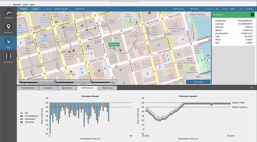
The Skydel Real-Time Performance graphs illustrate the software-defined engine’s low latency during a GNSS simulation. (Screenshot: Orolia)
A new real-time performance capability, now standard on all Skydel-powered GNSS simulators, achieves an ultra-low latency of 5 milliseconds. Skydel’s software-defined architecture is designed to meet the demanding GNSS simulation testing requirements in the automotive, military, space and other high-tech industries. Skydel also supports hardware-in-the-loop simulations without sacrificing ultra-low latency and high-end performance. A dashboard shows real-time performance graphs and enables users to grade the simulator’s performance, interpret data, diagnose inefficiencies, and optimize scenarios on the fly. As the system reaches its limits, it remains stable and fully operational, preserving the integrity of the simulation.
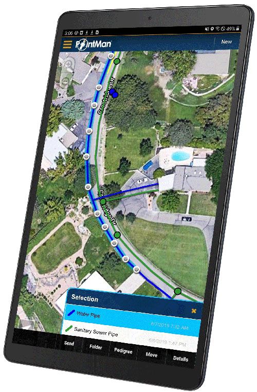
PointMan software is now integrated into the Vivax Metrotech vLoc3 with a GNSS real-time kinematic (RTK) receiver to create a utility-locate device. Using the RTK-Pro internal cellular module with 4G LTE capabilities, the operator can connect to the NTRIP RTK caster that provides RTCM 3 corrections. With the integration of PointMan with the vLoc3 RTK-Pro, critical buried infrastructure can be captured, recorded and displayed at survey-grade accuracy without additional external equipment or post-processing. The integration provides centimeter accuracy of the precise location of buried utilities in real time. Data collected includes the type of utility, the depth of cover and the utility’s precise location.
Geospatial and location intelligence for smart cities
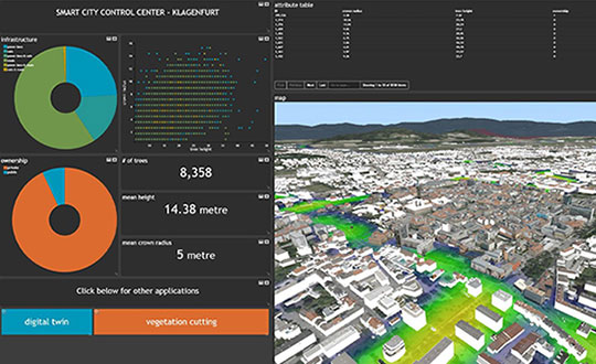
Screenshot: Hexagon Geospatial
M.App Enterprise 2021 is a significant update to the platform for creating geospatial and location intelligence applications. The latest release features new browser-based 3D capabilities and enhanced visual effects, plus the ability to create and configure custom applications more easily. It allows users to access LuciadRIA’s 3D features with support for panoramic imagery, shading, ambient occlusion and other visualization effects to build browser-based solutions. It also features a new browser app configurator that makes it easier to create spatio-temporal dashboards, or Smart M.Apps. Feature Analyzer now allows users to add and manage multiple datasets on the fly and set up workflows.