Blog

  • NGS releases beta tool for obtaining geodetic information

    NGS releases beta tool for obtaining geodetic information

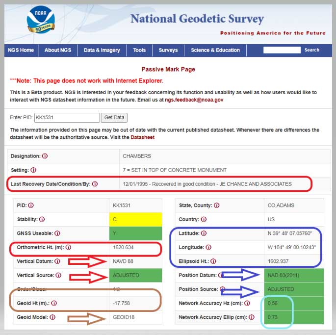
    NGS has developed a new beta tool for obtaining geodetic information about a passive mark in their database. This column will highlight some features (available as of Oct. 5, 2020) that may be of interest to GNSS users. It provides all of the information about a station in a more user-friendly format. The box titled “Passive Mark Lookup Tool” is an example of the webtool. The tool provides a lot of information so I have separated the output of the tool into several boxes titled “Passive Mark Lookup Tool — A through D.”

    I will highlight several attributes that I believe will be very useful to users, especially users of leveling-derived and GNSS-derived orthometric heights. I’ve highlighted several attributes in the box titled “Passive Mark Lookup Tool — A” that are important to users such as published coordinates, their datum and source, Geoid18 value, GNSS Useable, and the date of last recovery. All of these values are available on a NGS datasheet but, in my opinion, this provides the information in a more user-friendly format.

    Passive Mark Lookup Tool — A

    (https://beta.ngs.noaa.gov/datasheets/passive-marks/index.html)

    Image: National Geodetic Survey
    Image: National Geodetic Survey

    One calculation that the user can easily compute for marks that have been leveled to and occupied by GNSS equipment, is the difference between the published leveling-derived orthometric height and the computed GNSS-derived orthometric height. This may indicate that the mark has moved since the last time it was leveled to or that its height coordinate has been readjusted since the creation of the published geoid model.

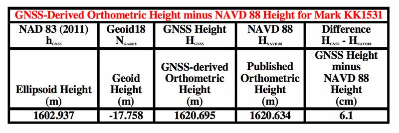
    The table below provides the calculation using the data from the box titled “Passive Mark Lookup Tool — A.” The calculation [HGNSS = hGNSS — NGeoid18; Difference = HGNSS — HNAVD 88] has been described in several of my previous columns (this one, for example).
    Data: National Geodetic Survey
    Data: National Geodetic Survey

    In this example, the difference between the GNSS-derived orthometric height and the Published NAVD 88 height is 6.1 cm. NGS is looking for comments on this beta webtool so if users would like this computation added to the tool, they should send a comment to NGS using the link provided on the site (This is a beta product. NGS is interested in your feedback concerning its function and usability as well as how users would like to interact with NGS datasheet information in the future. Email us at [email protected].) So, the user should ask the question, did the station move since the last time it was leveled?

    Another attribute that would be nice to be part of this tool is which station was used to create the hybrid geoid model. As of Oct. 5, 2020, users have to go to the Geoid18 webpage to get the information. The Excel file and shapefiles provide whether the station was used to create the Geoid18 model. In the case of this example, KK1531, CHAMBERS, the mark was not used in the creation of Geoid18 so NGS felt that the station may have moved and/or the GPS on Bench Mark residual was large relative to its neighbors. See NGS’s technical report on Geoid18 for more information on the creation of Geoid18. The GPS on Bench Mark residual analysis was described in several of my previous columns (see “The differences between Geoid18 values and NAD 83, NAVD 88 values” and “NGS 2018 GPS on BMs program in support of NAPGD2022 — Part 6” for examples).

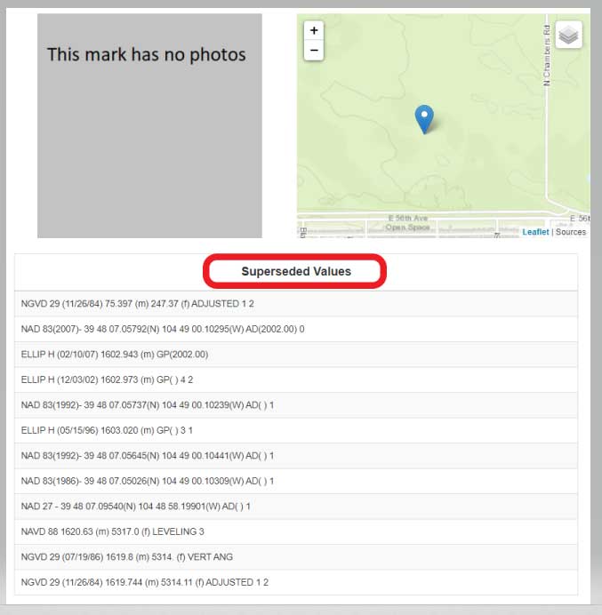
    The webtool provides a map depicting the location of the station, photos (if available), and previously published, superceded values of the mark. See the box titled “Passive Mark Lookup Tool — B.”

    Passive Mark Lookup Tool — B

    Image: National Geodetic Survey
    Image: National Geodetic Survey

    In the example of Chambers, KK1531, no photos were available. It would be helpful if a user would provide photos to NGS when visiting this station. (Note: NGS has a webtool for users to submit recovery information about a mark as well as to provide current photos of the station.) The new Passive Mark webtool also provides information about the survey projects that the mark has been involved in such as leveling and GNSS projects.

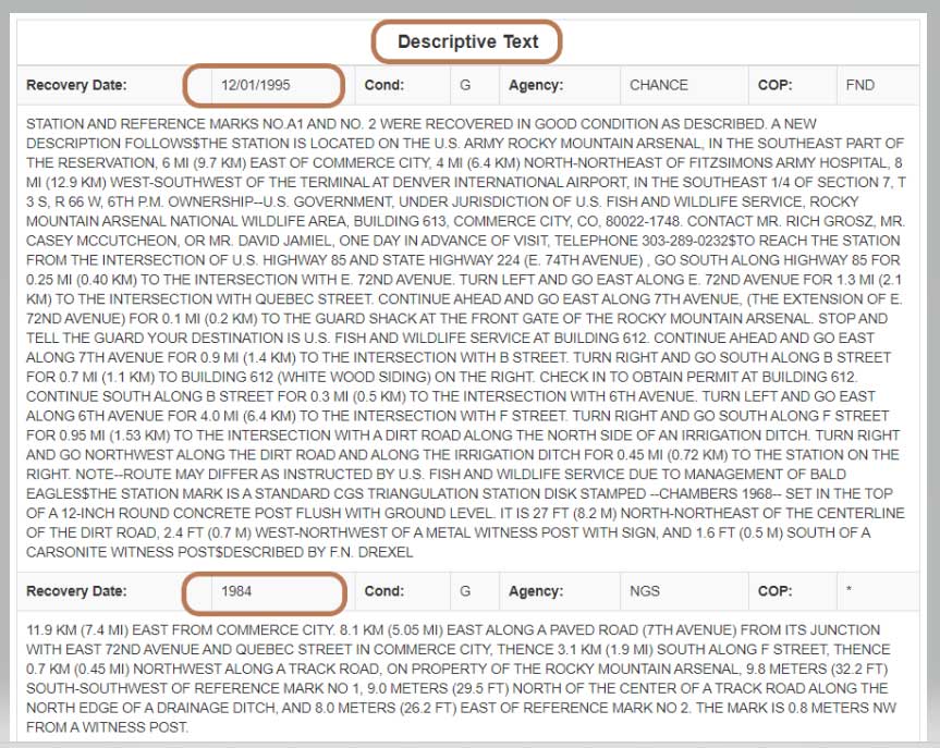
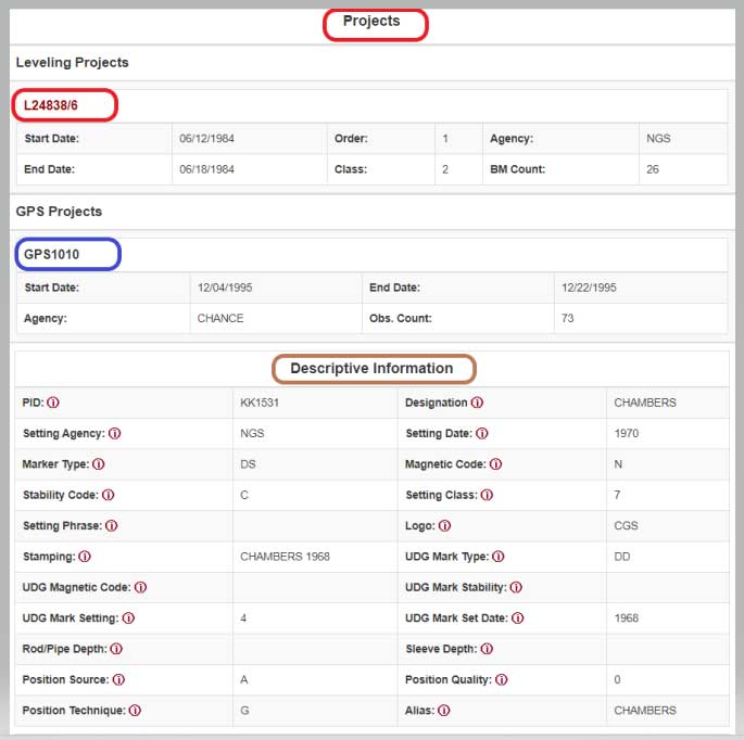
    In this example, mark CHAMBERS was leveled to in a 1984 first-order, class 2 leveling project (Leveling Line number L24838/6) and, in 1995, the mark was part of a GNSS project (GNSS Project GPS1010). It also provides all the descriptive text and recovery information (See boxes titled “Passive Mark Lookup Tool – C” and “Passive Mark Lookup Tool – D”).

    Passive Mark Lookup Tool — C
    Data: National Geodetic Survey
    Data: National Geodetic Survey

    Passive Mark Lookup Tool — D

    Image: National Geodetic Survey
    Image: National Geodetic Survey

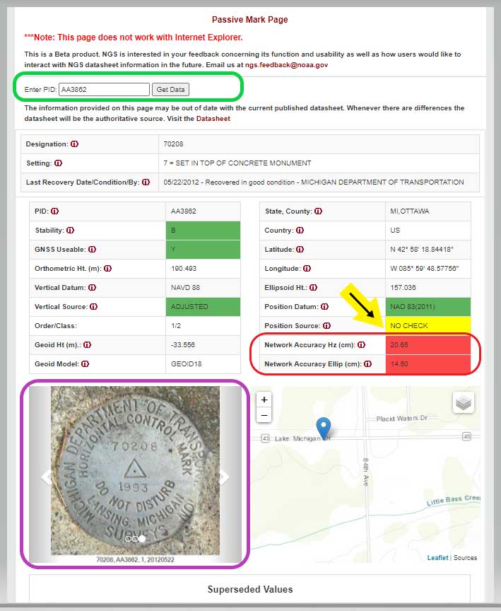
    I want to highlight a few other attributes of this webtool. The station, PID AA3862, has an interesting attribute that users should take note of; that is, the NAD 83 (2011) position source is NO CHECK. See box titled “Passive Mark Page for PID AA3862.”

    This means that the mark’s NAD 83 (2011) coordinates were determined without redundant observations. This is not a good survey practice but there are times that a project may contain check observations for some purpose or, more likely, the mark did contain other GNSS vector but they were rejected in the final adjustment. Either way, a good survey practice would be for users to verify the coordinates of these marks before using them.

    Passive Mark Page for PID AA3862

    Data: National Geodetic Survey
    Data: National Geodetic Survey

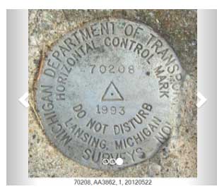
    As previously mentioned, the tool provides the location of the station on a map and photos if they are available. This is a really nice feature for anyone searching for the mark. The map can be enlarged as well reduced by clicking on the box. See boxes titled “Passive Mark Page for PID AA3862” and “Photos of Mark PID AA3862.” The box titled “Photos of Mark PID AA3862” provides all three photos of mark PID AA3862.

    Photos of Mark PID AA3862
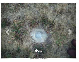
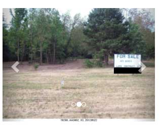
    Photo: National Geodetic Survey
    Photo: National Geodetic Survey
    Photo: National Geodetic Survey
    Photo: National Geodetic Survey

    Photo: National Geodetic Survey
    Photo: National Geodetic Survey

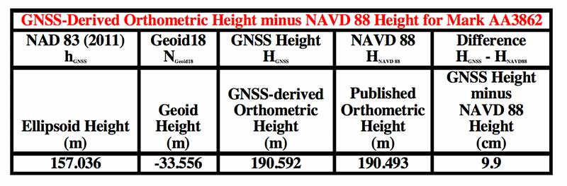
    It should be noted, according to the Geoid18 GPS on BMs dataset that users can download, this station, AA3862, was not used in the creation of Geoid18. The table below provides the difference between the GNSS-derived orthometric height and the published NAVD 88 height.

    In this example, the difference between the GNSS-derived orthometric height and the published NAVD 88 height is 9.9 cm. Also, the webtool provides the network accuracy values for the station. In this example, the horizontal network accuracy is 20.65 cm and the vertical network accuracy value is 14.50 cm (see highlighted values in box titled “Passive Mark Page for PID AA3862”). These are very large network accuracy values. This should be a flag to anyone that is using this station as control.
    Data: National Geodetic Survey
    Data: National Geodetic Survey

    As I previously mentioned, as a beta site, users should verify all information from the site. NGS is requesting feedback on this tool so they can improve it and make it an operational webtool. I encourage everyone to access the tool and check out a few of their favorite marks, and then send an email to NGS informing them of what you like, what you would like to change, and what you would like to see added to the tool.

    NGS is releasing this tool as a beta product to get feedback from users. As NGS states in the heading of the tool, they are interested in your feedback concerning its function and usability as well as how users would like to interact with NGS datasheet information in the future. Email NGS at [email protected].

    One last item that may be of interest to GNSS users is that NGS, working with the University Corporation for Atmospheric Research (UCAR), developed another online GNSS lesson (see box titled “New GNSS Lesson by NGS and UCAR”). These lessons are free but users must sign up to access the website and lesson.

    New GNSS Lesson by NGS and UCAR

    Image: National Geodetic Survey
    Image: National Geodetic Survey
  • Discovering a new GPS journal

    Discovering a new GPS journal

    Headshot: Ismael Colomina
    Ismael Colomina, chief scientist, Geonumerics

    Believe it or not, I remember clearly when one of my colleagues, at the beginning of 1990 in my office, made me aware of the upcoming GPS World journal. He went through the list of the already-appointed members of the editorial board and found some key names; Vidal Ashkenazi comes now to my mind. Later on, we received the first issue which, I am sure, must be carefully stored in the library of, at the time my employer, the Institute of Cartography of Catalonia (ICC).

    I also remember the day we were processing GPS kinematic measurements of an aerial survey conducted with Sercel NR52 and TR5SB C/A-code L1 GPS receivers (one was 33 x 38 x 33 cm3 and 18 kg; the other was even bulkier, and both operated on valves). That was for the new GPS aerial triangulation method.

    Shortly after, the application to airborne laser scanning came, and then INS/GPS integration for airborne remote sensing and mobile mapping. Then came the reinforcing high-speed loop of new applications, technology and challenges. The rest is history. An invariant of these 30 years has been that on our tables there were always one or more issues of GPS World. GPS World issues are always around us, part of our offices’ landscapes.

    Last but not least, I cannot tell apart the early days of the journal from its founding editor, Glen Gibbons, who has to be credited for about half the life of the magazine. He brought me onboard GeoConvergencia and, later on, when GeoConvergencia was stopped, to GPS World. I used to share with him ideas and results, and he used to scold me about not publishing them in his journal.

  • GPS technology will continue to transform agriculture

    GPS technology will continue to transform agriculture

    By Al Savage, John Deere

    Headshot: Al Savage
    Al Savage, John Deere

    While GPS technology originally started as a product of the space race, it has transformed in recent decades to be used in a variety of different industries. Its positioning and navigation capabilities make many everyday tasks easier to achieve. One industry that has continuously benefitted from this technology is agriculture.

    The world’s population is expected to reach nearly 10 billion people by 2050, effectively increasing global food demand by 50%, according to the United Nations. To meet these demands, global agricultural productivity will need to increase by 1.75% a year.

    Currently, productivity is only growing at an average rate of 1.63%, according to the Global Harvest Initiative. Precision agriculture and advanced technologies, such as automation, computer vision, artificial intelligence (AI) and machine learning are already on the farm helping farmers meet this demand, and GPS technology plays an especially significant and transformative role in making this happen.

    Game-Changer

    The development of automated driving and self-driving tractors has changed the game for farming by allowing technology to drive the machines with great accuracy, while farmers focus on other value-added tasks.

    Over time, that technology further developed in conjunction with other technology on the farm, such as GPS. Having a reliable way to keep equipment from running over crops is incredibly important to farmers.

    The GPS technology we use at John Deere is accurate within centimeters and complements the computer vision and sensors within the tractors with precise positioning in the field. This allows the farmer to drive faster without running over and damaging the crop. It also means farmers no longer cover the same ground twice.

    Other technology has also been installed on farming machines to provide added value, especially when paired with GPS. When used alongside sensors, GPS offers the potential to enable real-time data collection. Sensors throughout the field let farmers know things such as where each seed was planted or environmental conditions while spraying nutrients on their crops.

    Historical data from the farmer and garnered through the technology are turned into maps that, when combined with real-time information from the sensors, enable farmers to have even more accurate and precise information about what is happening next in the field, to ultimately optimize operations. This is critical as almost every job that gets done on the farm has to be completed in short time windows.

    Spatial intelligence provides a more vivid representation of what is happening in the field at all times so the farmer can make real-time decisions and plan for the future.

    Tasks such as tilling, planting, spraying and harvesting are easier when farmers have a more precise way to track their position. GPS technology, working in conjunction with computer vision cameras and sensors, allows crops to be distributed more evenly across a field and enables seeds to be planted at exactly the correct spacing and position to maximize yield.
    All of these tasks boost productivity and sustainability on the farm by providing farmers with the data to make informed, sustainable decisions.

    Photo: John Deere
    Photo: John Deere

    Machines Talking to Each Other

    Technology on farms has evolved to the point where machines can wirelessly communicate to each other in the field. This concept, known as machine-to-machine (M2M) communication, is also linked closely to GPS technology. Enabling machines to know where in the field another machine is and what work it has done in real time means the machines work as a team to get the job done in the most efficient way possible with no overlap. Coordination among machines helps farmers avoid redundant effort and the overuse of valuable inputs, which allows for more efficient use of resources and unlocks the potential of automation.

    As the agriculture community continues to work to meet the rising demands for food, fuel and fiber, GPS technology will play a key role to help farmers make more food more efficiently, sustainably and with greater consistency in results. This not only benefits the farmer’s business, but it impacts every single person in the world.


    Al Savage is the StarFire Network manager at John Deere.

  • Research Roundup: Navigation in urban environments

    Research Roundup: Navigation in urban environments

    Image: Moncherie/E+/Getty Images
    Image: Moncherie/E+/Getty Images

    Of the hundreds of papers researchers presented this year at the Institute of Navigation’s annual ION GNSS+ conference, which took place virtually Sept. 21–25, the following three focused on navigation in urban environments. Papers are available at www.ion.org/publications/browse.cfm.

    Low-Cost Single-Frequency PPP System

    Featuring multi-constellation global availability, fast convergence and continuous navigation solutions, Instant PPP (IP3) was developed as an ideal precise positioning solution for mass-market applications in urban environments. The low-cost single-frequency PPP system demonstrates 50-cm accuracy in open-sky and suburban environments, and is further enhanced to support precise positioning in urban environments. The IP3 library is uniquely designed and enhanced. For instance, the instant receiver velocity based on the Doppler observations and the coordinate changes calculated from the carrier-phase differences between two consecutive epochs are integrated for the one-step prediction of the receiver positions in the Kalman filter.

    Meanwhile, the weight of carrier phase, pseudorange and Doppler observations are smartly tuned as a function of signal-to-noise ratio (SNR) respectively. Additionally, quality control adapts to different scenarios, such as open-sky or urban environments. The receiver clock drifts for different constellations are specifically modelled in the velocity estimation to increase the degrees of freedom, which further enhances the solution availability in these extreme challenging situations.

    To evaluate the IP3 library in urban environments, real-time vehicle-based field tests were carried out with an IP3 evaluation kit in Calgary, Canada. Results indicate the IP3 library can provide 50-cm accuracy in suburban areas with 100% solution availability. In an urban environment with numerous high buildings, the positioning root-mean-square error (RMS) of IP3 degrades to meter level while the solution availability remains 100%. IP3 can provide precise positioning solutions with low-cost GNSS receivers even in urban environments.

    Citation. Hongzhou Yang, Fei Liu and Yang Gao, Profound Positioning Inc., Canada, “Precise Positioning into Urban Environments: A Low-Cost Single-Frequency PPP System.”

    A Sub-Meter Real-time Positioning Service for Smartphones

    A real-time positioning service for smartphones that meets a target threshold of 50 centimeters in urban environments is evaluated. The evaluation is possible through the Flamingo service, an API library for smartphone developers that enables higher accuracies than standard Google location services. The API is offered in a format that simply replaces Android location, streamlining its integration into new and existing applications that require better positioning. The service provides reference station infrastructure and correctional data products through a modified version of traditional NTRIP services. Duty cycling, low-quality clocks and high RF interference are common in a smartphone, so pre-filtering algorithms have been designed and calibrated to reject and de-weight poor measurements.

    Based on proximity to a local base station, the service decides whether to use RTK or PPP-like processing. Performance is assessed on positioning accuracy, reliability and availability. Different operational environments are tested, such as pedestrian navigation in a congested area, and cycling scenarios. These are chosen to closely correspond to various applications. Rather than proving ideal test conditions and post-processing to optimize performance, the study focuses on realistic, real-time processing inside a smartphone.

    Results are collected through a simple logging app that uses the Flamingo API. A target is set for 50 cm or better accuracies, where current smartphone positioning is within only a few meters. This enables mass-market location services to be applied in new markets such as augmented reality, lower accuracy surveying, GIS asset collection, and navigation assistance applications.

    Citation. Joshua Critchley-Marrows, William Roberts, Malgorzata Siutkowska, Maria Ivanovici, NSL, UK; Valentin Barreau, Soufian Ayachi, Laurent Arzel, Telespazio, France, “A Sub-Meter Real-Time Positioning Service for Smartphones.”

    The Path to Robust Municipal PNT

    This research identifies where municipal governments fit in the positioning, navigation and timing (PNT) ecosphere, their awareness of PNT-related issues, whether and how they are approaching these issues, and actions they can take to improve their services to citizens and travelers. Lessons from other areas are applied, such as the resource typing construct used in FEMA’s National Incident Management System, to develop best practices for city PNT activity. This work will guide cities in addressing this important area and assist policy makers in efforts to involve cities in the development and implementation of PNT processes.

    Citation. Steven Polunsky, Alabama Transportation Policy Research Center, University of Alabama, “The Path to Robust Municipal PNT.”

  • Prominent companies describe GNSS solutions

    Prominent companies describe GNSS solutions

    In a special advertiser-sponsored section of our October issue, we spoke with prominent GNSS companies about their current solutions for today’s industry challenges.


    Q&A with CAST Navigation

    Answered by Lou Pelosi, vice president

    Lou Pelosi, vice president
    Lou Pelosi, vice president

    Q: What is your most proven GNSS solution?

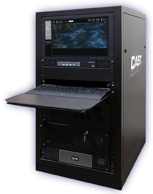
    A: CAST Navigation does not supply GNSS receivers (GNSS solutions), rather we manufacturer GNSS simulators which are used to test GNSS receivers. CAST has had the most success with our GNSS/INS simulator. It provides an Embedded GPS Inertial (EGI) navigator with coincident GPS and inertial data. The EGI “thinks” it is moving while it remains stationary.

    With our GNSS/INS simulator, the operational flight program of the EGI can be tested. During development of a platform’s navigation system, the CAST simulator is used to recreate the identical test conditions as the EGI’s software is modified. Once the platform’s navigation system is finalized, the output of the EGI is used to drive other systems, such as flight control or radar.

    The GNSS/INS simulator can also include Controlled Radiation Pattern Antenna (CRPA) test features. If the EGI being used by the platform has an anti-jam antenna, the simulator can also test that feature.

    The CAST GNSS/INS simulator has proven to be a key piece of equipment in system integration laboratories as new aircraft are developed.

    Photo: CAST Navigation
    Photo: CAST Navigation

    Q: What are the solution’s key specs?

    A: A key element of our GNSS/INS simulator is the inertial model contained in the simulator. It is a whole value inertial model rather than an error model. In its normal state, it reacts in the same manner as the actual inertial of the EGI. It also had degraded modes that are used to simulate hardware failures. When analyzed by the EGI manufacturers, its noise characteristics are almost identical to fielded navigation systems.

    Q: What are the solution’s key features and benefits?

    A: The most obvious benefit of using a CAST GNSS/INS simulator is cost savings. Even with the cost of lab equipment and personnel, there is still a savings over flight testing. A key feature of using a simulator for testing is its repeatability. Every time you rerun a test; the conditions are the same. In the real world, the satellites change constantly. Being able to accept real-time trajectory data is another key feature of CAST simulators. Instead of using our internal point mass model for scenario generation, an actual flight profile can be sent to the simulator from an external computer.

    CAST has also been authorized by the GPS Directorate to provide classified functions to authorized users. Available options include Y-code, SAASM and M-code MNSA.

    castnav.com

    [email protected]


    Q&A with Kolmostar

    Answered by Lucy Fan, VP of Sales and Marketing

    Lucy Fan, VP of Sales and Marketing
    Lucy Fan, VP of Sales and Marketing

    Q: What is your most proven GNSS solution?

    A: Kolmostar specializes in ultra-low-power, instant cold-boot GNSS positioning solutions for internet of things (IoT) applications, mobile devices and beyond.

    Q: What are the solution’s key specs?

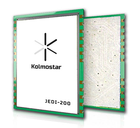
    A: Our advanced GNSS positioning module JEDI-200 is specially designed for location-based IoT applications such as asset tracking, fleet management, pet/livestock tracking, smart wearables and share economy. It is also optimized for integration with LPWAN (low power wide area network) technologies such as LoRaWAN®/NB-IoT/LTE-M to provide the ultimate ultra-low-power profile for IoT applications. There are two outstanding advantages of JEDI-200: ultra-low-power and instant cold-boot. With 25 mW power consumption and the revolutionary 1-second TTFF (time to first fix), JEDI-200 is able to reduce the energy consumption to get one position fix by up to 120x compared to traditional GNSS modules on the market.

    Q: What are the solution’s key features and benefits?

    Photo: Kolmostar
    Photo: Kolmostar

    A: GNSS/GPS sensors are one of the most power-consuming sensors in IoT or mobile devices. Battery life will be significantly shortened when GNSS/GPS sensors are turned on. Hence, many IoT and mobile devices either do not include GNSS/GPS sensors or have to equip themselves with very large batteries, incurring much inconvenience and cost. Kolmostar’s ultra-low-power and instant cold-boot JEDI-200 module is specially designed to solve this long-standing industry pain point.

    With its ultra-low-power feature, JEDI-200 is able to reduce the energy consumption to get one position fix by up to 120x when compared to traditional GNSS modules. IoT devices with very limited-sized batteries are now able to have GNSS positioning ability while still maintaining a battery life up to 10+ years. Another key feature of JEDI-200 is instant cold boot. Unlike traditional GNSS modules’ 30-second TTFF in cold boot, JEDI-200 can achieve an instant 1-second TTFF, providing a better and more seamless customer experience when short latency/response time is particularly desired in certain applications. In addition, JEDI-200 is optimized for LPWAN technologies such as LoRaWAN®/NB-IoT/LTE-M, further reducing both the cost and the power consumption of devices’ wireless communication, which is another big challenge most IoT and mobile devices previously faced.

    kolmostar.com

    [email protected]


    Q&A with Racelogic

    Headshot: Julian Thomas
    Julian Thomas, founder & managing director, Racelogic

    Answered by Julian Thomas, Managing Director

    Q: What is your most proven GNSS solution?

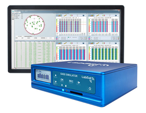
    A: The LabSat 3 Wideband GNSS simulator offers multi-constellation and multi-frequency capabilities for reliable, repeatable and consistent testing. Its one-touch Record and Replay provides an efficient way to test and develop GNSS receivers without the cost, inconvenience and limitations of live-sky signals. Combining LabSat with the custom simulation software SatGen enables the creation of GNSS RF I&Q or IF data files based on a bespoke scenario, allowing for almost any kind of test at a set time, date and location.

    Q: What are the solution’s key specs?

    A: With three channels, a bandwidth of up to 56 MHz and 6-bit sampling (3-bit I and 3-bit Q), LabSat 3 Wideband can handle almost any combination of constellations and signals that exists today, with plenty of spare capacity for future planned signals.

    Q: What are the solution’s key features and benefits?

    A: LabSat 3 Wideband is small and affordable, making it an ideal solution for companies to provide their employees with a suitable method of testing their GNSS devices whilst working from home. In addition to its compact size, an internal battery delivers up to two hours of run time to record scenarios in even the most challenging field environments.

    Photo: Labsat
    Photo: Labsat

    It is incredibly user friendly with one touch record and replay and an HTML interface that makes setup simple and problem-free. A range of additional signals can also be recorded and synchronized to the GNSS input: dual-CAN, RS232 and digital inputs are simultaneously captured, increasing the level of playback realism and allowing for a wider range of testing.
    The latest version of SatGen can be used to create a single scenario containing all the upper and lower L-band signals for GPS, Galileo, GLONASS, BeiDou and NavIC, and takes advantage of the LabSat 3 Wideband’s ability to read RF data at up to 95 MB/s. Creating an artificial scenario using SatGen allows for precise control of the data content, creating a standardized file for repeatable testing and carrying out true comparisons between receivers.

    The versatility of the LabSat 3 Wideband makes it a familiar sight on the desks and benches of technology companies around the world. From GNSS device and application testing to receiver sensitivity and end-of-production-line testing, LabSat 3 Wideband is a perfect testing partner.

    labsat.co.uk

    [email protected]


    Q&A with Trimble

    Q: What is Trimble OEM GNSS’ most proven GNSS solution?

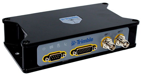
    A: The Trimble BX992 is the flagship product from the Trimble OEM GNSS portfolio, proven in multiple environments and applications. Powered by the BD992-INS receiver module, this rugged yet compact enclosure allows original equipment manufacturers and system integrators to rapidly integrate precise position and orientation data to guidance, control and autonomous applications. Continuous data sets collected from test sites and real-world applications around the world have been used to create a powerful engine that performs in the most challenging of GNSS environments.

    The Trimble BX992. (Photo: Trimble)
    The Trimble BX992. (Photo: Trimble)

    Q: What are the solution’s key specs?

    A: The Trimble BX992 delivers low-latency 100-Hz centimeter-level positions with tight integration of IMU sensor data and GNSS observations in the RTK/RTX engine. The rugged IP67 enclosure supports multi-frequency tracking from GPS, Galileo, GLONASS, BeiDou, QZSS and NavIC constellations. The dual-antenna inputs allow rapid and robust alignment of onboard gyro sensors. With Trimble RTX correction services, the BX992 delivers reliable, high-accuracy positioning without a local base station or cell modem.

    Q: What are the solution’s key features and benefits?

    A: The BX992 is a full-featured solution with an onboard spectrum analyzer, a critical tool for developers to identify interference from unwanted signals, thus allowing products to be released to the market within specification and on schedule.

    trimble.com/Precision-GNSS

    [email protected]

  • L5-only receiver designed for mobile phones

    L5-only receiver designed for mobile phones

    Greg Turetsky, oneNav Inc.
    Greg Turetsky, oneNav Inc.

    GNSS receivers first reached the commercial domain in the early 1980s. They were bigger than your average carry-on suitcase, weighed more, and consumed so much power that they needed to be plugged into an outlet. But technology advanced quickly, and by the mid-1980s commercial GNSS receivers were appearing in survey and marine markets.

    Generation 1. The first generation of truly mobile receivers, in the late 1990s, used only L1 C/A code and were typically found in rugged handhelds for outdoor enthusiasts. The receivers began appearing in mobile phones in the late 1990s.

    Gen 2. The second generation added GLONASS. These receivers had to have wider bandwidths on the order of 20-30 MHz to support the GLONASS FDMA signals at a slightly offset frequency from GPS L1.

    Gen 3. These receivers added support for Galileo. They started appearing in mainstream cellphones in about 2014. These phones still retained a single frequency front end in the L1 band, but had separate digital processing chains for all three satellite systems.

    Gen 4. This evolution added support for BeiDou and a single sideband L5 receiver where BeiDou, Galileo and GPS all have modernized signals. These receivers first appeared in phones in 2019 because of the added size, power and complexity of supporting a dual-band receiver. The front end is a burden on many phone models, especially with the rise of 5G. Plus, the L1 band has reliability issues with jamming and interference. The receivers only support a single sideband at L5 and are not utilizing the full capability of L5.


    Read the full white paper from oneNav.


    Why Consumer Devices Need L5

    Every GNSS user in every segment benefits from using the new, modernized signals in the L5 band. L5 signals are more accurate, reliable and available in sufficient numbers to support all user segments. Here are the major advantages of L5 over L1.

    • Signal structure (narrow correlation peak) accuracy
    • Wide bandwidth (multipath mitigation) accuracy
    • Pilot codes (longer coherent integration increasing SNR)
    • Multiple constellations and signals with common signal structure
    • Stronger signal transmission
    • Cleaner band with less interference
    • Signal availability

    The benefits of L5 are clear. That’s why many GNSS suppliers have started building L1/L5 solutions, and they are starting to appear in smartphones. It seems to be a natural progression to add an L5 receiver chain on top of an existing L1 solution and be able to reap the benefits. But bringing along the legacy L1 solution could actually have a negative impact on the overall solution.

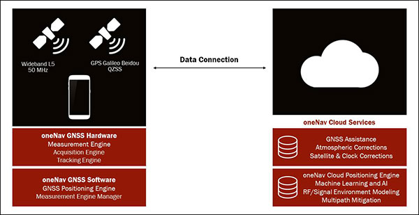
    The oneNav L5 mobile GNSS system architecture. (Image: oneNav)
    The oneNav L5 mobile GNSS system architecture. (Image: oneNav)

    L5 Wideband Receiver

    We set out to build a fifth-generation GNSS receiver for mobile consumer products. Its single-frequency design only uses the modernized, wideband signals at L5. It has an acquisition engine sophisticated enough to acquire L5 signals directly and a navigation engine that uses artificial intelligence/machine learning (AI/ML) techniques to fully exploit all the signals in 50-MHz wideband at L5.

    Optimized engine. Building an acquisition engine for the L5 signal is a huge mathematical task. Since the codes are 10 times longer and have a 10 times faster chipping rate, it’s a 100 times more difficult search problem. The oneNav engine solves that problem with a customized array processor that has a GPU-like approach, maintaining TTFF.

    Single-frequency architecture. Pure L5 architecture eliminates the need for a second RF chain. The oneNav L5 engine uses common hardware for signals from all GNSS systems.

    Increased sensitivity. The L5 signal has a modernized signal structure that allows for increased sensitivity for both acquisition and tracking. With wideband architecture, all parts of the L5 signal can be combined for maximum performance and significantly more signal strength than L1.

    Improved time to fix. Dual-band receivers first get a fix on L1 and then begin the acquisition process on L5. By performing the L5 acquisition directly, we save time.

    Acquisition reliability. The L1 signal structures do not have the longer primary codes and the secondary codes like modernized signals on L5 that mitigate many of the reliability problems associated with cross correlation, jamming and spoofing.

    Improved tracking and measurement. Using the full bandwidth allows a more sophisticated channel estimation than a simple pseudorange measurement. With multiple signals contained within the L5 wideband signal, we gain advantages from channel diversity.

    AI/ML navigation engine. A cloud-connected navigation engine uses advanced AI/ML techniques to further improve navigation accuracy. Sophisticated ML techniques to predict if the received signal is line of sight and predict the measurement error caused by multipath. The cloud service allows reflected signals to be used correctly in the navigation solution rather than being excluded due to their multipath content. A sophisticated pattern-matching-based positioning algorithm combines the pseudorange measurements and the environment’s 3D building map model to enhance positioning accuracy in deep urban canyons.

    IP Core

    We designed the oneNav receiver as a licensable IP core rather than a discrete silicon solution. The complete solution includes all the firmware and an RF front-end reference design from antenna to A/D converter. This allows customers to determine how to best bring the oneNav advantages to their products.

    The IP core can be integrated into a larger ASIC such as a modem or an SOC. It could also be implemented as a discrete silicon solution. The RF could be combined into any of these solutions or implemented with other RF components in the system. The measurement and position engine firmware can be run on a dedicated CPU or shared in either the same or different CPUs for flexible system integration optimal for various applications. The IP core is both process independent and scalable. An integrated GNSS core means that GNSS performance can be maintained across multiple platforms and silicon generations, providing consistency of measurement and positioning performance needed to maintain system reliability and fusion.

    In my opinion, the Pure L5 wideband receiver can be considered a next generation — or fifth generation — of GNSS for mobile consumer products.


    Greg Turetzky is vice president, Product, for oneNav, and a member of GPS World’s Editorial Advisory Board. Read the full white paper from oneNav.

  • NAVSYS’ role in WAAS

    NAVSYS’ role in WAAS

    Headshot: Alison Brown
    Alison Brown, president & CEO, NAVSYS Corporation

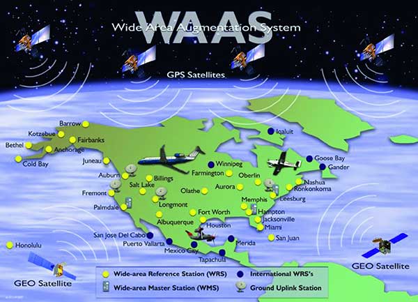
    Thirty years ago, NAVSYS was deep into the development of the Wide Area Augmentation System (WAAS). I had the honor of being the chair of the RTCA SC-159 Integrity Working Group, which developed the first concepts for what evolved into three integrity standards for GPS: multi-sensor integration, receiver autonomous integrity monitoring (RAIM) and wide-area differential GPS using a GPS integrity channel (GIC) to broadcast corrections over a geostationary overlay.

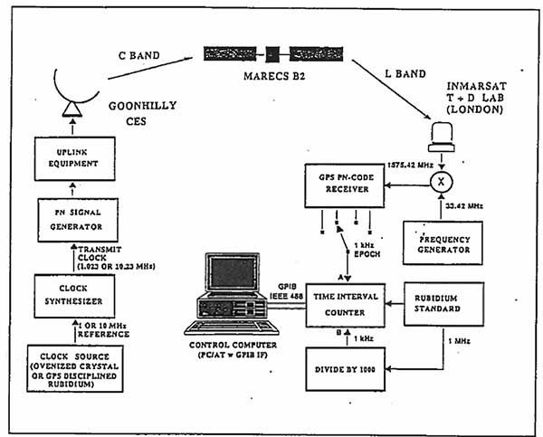
    NAVSYS, working with Inmarsat Corporation, built the first prototype WAAS SIGGEN equipment, which was deployed at the Coonhilly Coast Earth Station and used to transmit an L-band C/A-code signal over the Inmarsat Atlantic Ocean Region MARECS-B satellite to a software GPS receiver that we had developed and installed at Inmarsat’s Test and Development Laboratory in London.

    First Inmarsat Geostationary Overlay Test-Bed, 1991. (Image: NAVSYS)
    First Inmarsat Geostationary Overlay Test-Bed, 1991. (Image: NAVSYS)
    Image: FAA
    Image: FAA

    This evolved into the FAA’s WAAS program, which used the NAVSYS SIGGEN for the initial deployment, test and evaluation. The algorithms developed by NAVSYS were ultimately licensed to Raytheon for use on the operational WAAS and MSAS systems.

  • ESA studies lay path to navigating the moon

    ESA studies lay path to navigating the moon

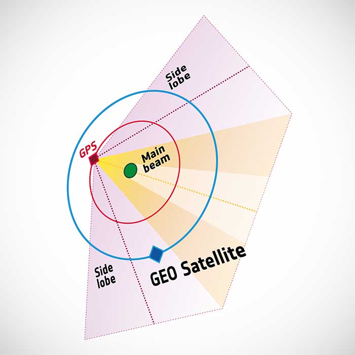
    Illustration of side-lobe signals from GPS satellites. (Image: ESA)
    Illustration of side-lobe signals from GPS satellites. (Image: ESA)

    Two European Space Agency studies found that the signal from navigation satellites orbiting Earth could be used to navigate the moon’s surface.

    News from the European Space Agency (ESA)

    To pinpoint a location accurately, a receiver — in smartphones or on a spacecraft — needs to collect and combine signals from at least four navigation satellites. The receiver determines its distance from each of the satellites by measuring the time that it takes for the signal to travel from the satellite to the receiver.

    Navigation satellites aim their antennas directly at Earth. Satellites orbiting above the navigation (GPS in this image, but Europe’s own navigation system is Galileo) constellation could only hope to detect signals from Earth’s far side. Now spacecraft can make use of signals emitted sideways from navigation antennas, within what is known as “side lobes.” Just like a torch, they shine energy to the side as well as directly forward.

    Navigation satellites orbit 22,000 kilometers above Earth’s surface. As they point in the direction of Earth, any spacecraft between them and Earth are served well by their signal. But around 10 years ago, engineers started demonstrating that spacecraft outside the orbit of navigation satellites could also navigate in space using “spill over” signal from the satellites.

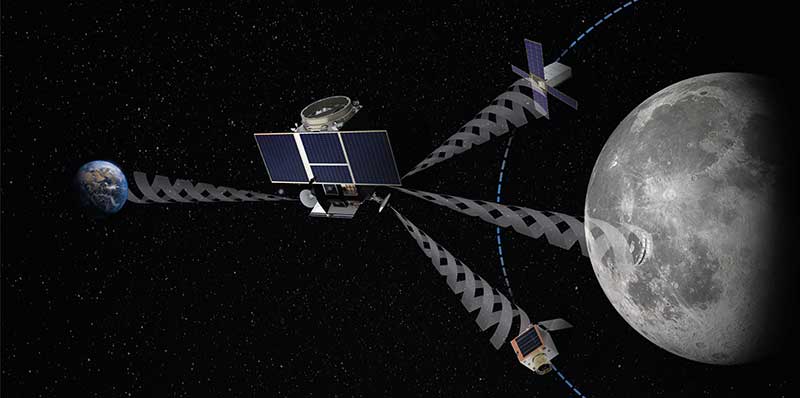
    Then in 2012, two discovery and preparation studies explored a seemingly radical question: could this spillover signal even be used to navigate our way around the moon, and if so, what kind of receiver would we need to build to be able to use these signals?

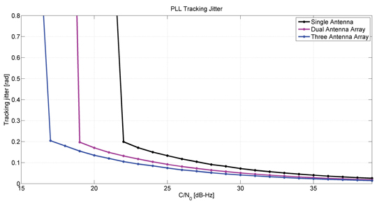
    The studies found that the signal from navigation satellites orbiting Earth could be used to navigate the moon’s surface. But with the signal being so weak, they found that a new type of receiver would need to be built, and at the time there was no clear application for this.

    Eight years later, ESA invested in the development of such a receiver, and is exploring whether it could be demonstrated on the Lunar Pathfinder mission. ESA is collaborating with Surrey Satellite Technology Ltd. and Goonhilly Earth Station on this mission, which will provide exciting new opportunities for science and technology demonstration. In particular, it will help lay the groundwork for providing navigation services around the moon, currently studied through two ESA NAVISP activities and culminating in the Moonlight initiative.

    “We have now accurate simulation results that show that navigation signals may be used at moon orbit and provide good performances,” said Dr. Javier Ventura-Traveset, head of the Galileo Science Office and in charge of coordinating all GNSS moon activities for ESA’s Navigation Directorate. “And with an innovative receiver in Lunar Pathfinder, we could have the first ever experimental evidence of this.

    Artist’s impression of the Lunar Pathfinder mission. (Image: SSTL)
    Artist’s impression of the Lunar Pathfinder mission. (Image: SSTL)

    “Furthermore, we are also studying how existing navigation constellations may be complemented by additional moon-orbiting satellites, providing additional ranging signals for an optimal navigation service including moon landing and moon surface operations. This is being done as part of the ESA NAVISP program and through the ESA Moonlight initiative.”

    “The discovery and preparation studies have been eye-openers and they are currently being followed up by a NAVISP activity aiming to develop the highly sensitive spaceborne navigation receiver planned to fly on board Lunar Pathfinder,” said ESA Radio Navigation Engineer Pietro Giordano. “This technology will enable improved performances and much more cost-effective ways to navigate and operate missions to and around the moon.”

  • Webinar to highlight GPS program updates, SMC space enterprise architecture

    Webinar to highlight GPS program updates, SMC space enterprise architecture

    GPS World, in conjunction with Spirent Federal Systems, will be hosting a webinar on Oct. 8 that will cover GPS program updates, as well as the program’s role in the Space and Missile Systems Center’s (SMC) space enterprise architecture.

    The event will also discuss the effects of COVID-19 and any future plans for the GPS program.

    Event speakers will include Col. Ryan Colburn, director of SMC’s Spectrum Warfare Division; Shawn Ryan, BAE Systems Navigation & Sensor Systems director of business development for SMC; Mike Shepherd, associate director of business development at Collins Aerospace Mission Systems; and Christopher Hogstrom, engineer at Spirent Federal Systems.

    Headshot: Ryan Colburn

    Col. Ryan Colburn leads a team charged with designing and integrating the United States Space Force’s current and future integrated satellite communications and position navigation and timing enterprise architectures. He works with military, commercial, allied and government partners to ensure SMC is able to design, acquire, integrate and field the space systems needed to support today’s warfighters.

    Headshot: Shawn Ryan

    Shawn Ryan provides local leadership for all SMC and Los Angeles Industrial NSS efforts and engagement. NSS, headquartered in Cedar Rapids, Iowa, develops, designs and manufactures the most advanced GPS receivers and anti-jam GPS antenna electronics for military applications.

    Headshot: Mike Shepherd

    Mike Shepherd leads integrated business development for A-PNT, FVL, TITAN and JADC2. Previously, he was the senior manager of the ground U.S. military GPS receiver business and managed major accounts for all branches of the U.S. military users of GPS and A-PNT systems.

    Headshot: Christopher Hogstrom

    Christopher Hogstrom joined Spirent Federal in 2020. He currently supports various engineering efforts as well as customer trainings and product demos. He has worked extensively with adaptive beamforming and its applications in GPS anti-jam technologies. Hogstrom received his Bachelor and Master of Science in Electrical engineering from Brigham Young University.

    Register for the event here.

  • Via acquires Fleetonomy for logistics and delivery technology

    Via acquires Fleetonomy for logistics and delivery technology

    Photo: Scharfsinn86/iStock / Getty Images Plus/Getty Images
    Photo: Scharfsinn86/iStock / Getty Images Plus/Getty Images

    Via, a provider of digital infrastructure for public mobility systems, has acquired Fleetonomy, a developer of fleet management software.

    Fleetonomy was founded in 2017 by CEO Israel Duanis and CTO Lior Gerenstein, with the vision of building the next generation of fleet management and optimization platforms, suitable for the challenges and opportunities that came with the shift to fleet-based on-demand services.

    According to Via, the purchase accelerates its expansion beyond public transit and strengthens its ability to meet increasing global demand for efficient, flexible solutions for logistics and delivery.

    Via’s technology is currently used in more than 150 cities and transit operators across the globe to power intelligent transit and delivery platforms, Via said. The need for essential transit and goods delivery has continued to grow during the COVID-19 pandemic, and Via plans to apply Fleetonomy’s technology and expertise in demand prediction and fleet utilization to advance its digitally-powered logistics solutions.

    “As we continue to build the next generation of public transportation and delivery infrastructure, we are proud to partner with Fleetonomy to step into this new phase of growth,” said Via Co-Founders Daniel Ramot and Oren Shoval. “We have been consistently impressed by Israel, Lior and the entire Fleetonomy team, and by the beautifully-designed and exceptionally-engineered products they have created. We share a vision for the future of mobility and look forward to realizing this vision together.”

  • From racecars to boundless opportunities

    From racecars to boundless opportunities

    Headshot: Julian Thomas
    Julian Thomas, founder & managing director, Racelogic

    When I started Racelogic nearly 30 years ago, I could not have foreseen how intrinsically embedded GPS would become in my life. I started out with the goal of supplying electronic control systems to the motorsport world. From traction control systems to paddle shifters for automatic cars, our technology rapidly built a reputation for quality and accuracy. It was this pursuit of accuracy that led me to GPS.

    GPS can be used for a wide variety of applications, but still not many people realize just how accurate it is for measuring the speed of a moving object. It was whilst looking for a solution to measure ground speed to use as a reference for a traction control system for a 4-wheel drive rally car that we came across an Ashtech 20-Hz GPS engine and were amazed to find out just how accurate the speed output was. This was a turning point in Racelogic’s history, which led to the development of one of our best-known products, the Velocity Box (VBOX), which is used to measure speed, distance and acceleration of vehicles for use in the test and development of new cars.

    It is undoubtedly an exciting time for GNSS. New signals and constellations are delivering a huge improvement in performance, which has spurred the release of new, lower cost, game-changing products into the marketplace. With cm-level position now becoming affordable for almost any application, it will be fascinating to follow how this changes the face of the positioning market, and see what innovations and novel applications will appear.

    Delivering solutions to these emerging applications will require agility and flexibility to integrate GPS with sector-specific technology. If this can be combined with solutions that overcome some of the limitations of GPS, then the opportunities are boundless. I for one am excited to see where the next 30 years takes us.

  • Earth-imaging and scientific payloads arrive for Ariancespace mission

    Earth-imaging and scientific payloads arrive for Ariancespace mission

    Earth-imaging and scientific payloads have arrived in French Guiana, both designed for Ariancespace’s Vega mission in November.

    The spacecraft were delivered by a chartered Antonov AN-124 cargo jetliner that touched down at Cayenne’s Félix Eboué Airport. They were then transported by road to the Spaceport, where processing is now underway in separate clean room areas of the S5 payload processing facility.

    According to Arianspace, the Vega’s mission with these satellites is designated Flight VV17 in Arianespace’s launcher family numbering system.

    The two satellites include SEOSAT-Ingenio, Spain’s optical observation satellite, and Taranis.

    SEOSAT-Ingenio

    Arianespace’s launch services contract for the SEOSAT-Ingenio satellite was signed with the European Space Agency for Spain’s Center for Development of Industrial Technology (CDTI). The satellite features optical technology, developed primarily by the Spanish space industry with Airbus in Spain as the prime contractor. Its liftoff mass will be approximately 840 kg.

    High-resolution imagery from SEOSAT-Ingenio is to be used for civil and military purposes in such applications as security, land management, natural resources, border surveillance, agriculture and natural disaster crisis management, Arianspace said. The satellite is owned by the Spanish Ministry of Science and Technology, with the CDTI leading the spacecraft project by delegation and also assuming its cost.

    Spain’s SEOSAT-Ingenio (left) is readied for the startup of its checkout process in the Spaceport’s S5 payload preparation facility, which will begin after the external wrapping is removed. The French Taranis scientific satellite (right) undergoes an initial inspection in another of the S5 clean room areas. (Photos: Arianspace)
    Spain’s SEOSAT-Ingenio (left) is readied for the startup of its checkout process in the Spaceport’s S5 payload preparation facility, which will begin after the external wrapping is removed. The French Taranis scientific satellite (right) undergoes an initial inspection in another of the S5 clean room areas. (Photos: Arianspace)

    Taranis

    Taranis, or Tool for the Analysis of RAdiation from lightNIng and Sprites, is named after the god of thunder in Celtic mythology. It will study impulsive transfers of energy between the Earth’s atmosphere and the space environment that occur above thunderstorms.

    Funded by the French CNES space agency, this satellite will have a liftoff mass in the 200-kg. category and is to provide data on the transient luminous events that have been observed in the past 30 years, particularly such phenomena that are called sprites, jets and elves.

    According to Arianspace, both SEOSAT-Ingenio and Taranis will operate in similar orbits at an altitude of approximately 700 km. In ride-sharing this launch on Arianespace’s light-lift Vega launcher, the two spacecraft will be deployed by a VESPA payload dispenser, produced by Airbus in Spain for Avio.