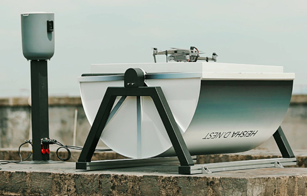
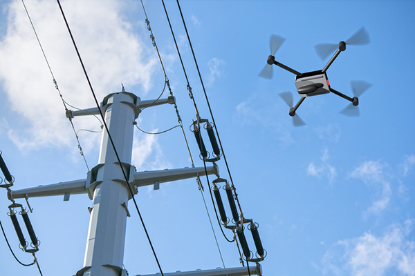
Heisha, a drone-charging solution and unattended drone system provider, has launched a new drone-in-the-box hardware platform, D.NEST.
D.NEST is an automatic drone-in-the-box hardware platform compatible with DJI drones, open-source project drones and vertical take-off and landing (VTOL) aircraft.
Based on Heisha’s third-generation charging pad C500, D.NEST is a reliable and stable automatic drone charging solution. Equipped with a built-in AI computer, remote-control base and local router, D.NEST is easy to maintain and redevelop, according to the company. Additionally, the hardware platform can be a data center and control center for different robots.
Heisha operates an open-source interface API and SDK, making it flexible. Designed for use with the DJI Mavic and Phantom series, D.NEST can also be customized for use with the M200, M210, M300, M600, open-source UAVs and VTOL fixed-wing UAVs.
Equipped with the 5-in-1 PCB control K100 and industrial-level materials, Heisha also provides a useful, stable and cost-effective drone-charging platform.
RedTail Lidar System’s RTL-400 delivers the trifecta
Summer is here, and with it comes the challenge of creating accurate topographic maps under tree canopies. The adoption of drone-based, 3D light detection and ranging — or lidar — is emerging as the go-to sensing technique to meet this challenge consistently, safely and cost effectively.
Designed specifically for use on small drones, the RTL-400 from RedTail Lidar Systems was developed with technology licensed from the U.S. Army Research Laboratory (ARL). The RTL-400 is designed to provide high-resolution 3D images of objects on the ground, flying at an altitude of up to 400 feet.
The RedTail team recently partnered with the West Virginia Department of Environmental Protection (WVDEP) Division of Mining and Reclamation to demonstrate the RTL-400’s ability to generate an accurate digital terrain model (DTM) under “leaf on” conditions. This can be challenging, because pulsed laser light needs to reach the ground to generate laser light ground returns.
One mission of the WVDEP Division of Mining and Reclamation is to assure compliance with the West Virginia Surface Mining and Reclamation Act and other applicable state laws. This task requires ongoing monitoring, mapping and assessment of sites across the state that are actively being reclaimed.
Originally utilizing photogrammetry to generate point clouds, the WVDEP was unable to create the accurate, under-canopy DTMs that they desired. Looking for an alternate method, they began to consider lidar.
The RedTail lidar team met with WVDEP representatives at a mine reclamation site in a remote area of south-central West Virginia. The terrain was a mixture of rolling hillside covered with grasses, brush and tree stands.
The RTL-400 demonstration flight mapped approximately 20 acres of the reclamation site in 12 minutes, flying at an altitude of 196 feet and a speed of 18 mph.
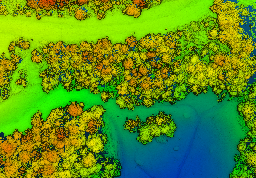
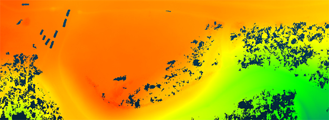
Once the data was collected, a digital terrain model (DTM) was created, revealing the RTL-400’s ability to generate the high-resolution, high-density point cloud needed to accurately map the terrain beneath the tree. 
Digital terrain model (DTM) generated from RTL-400 point cloud. (Image: RedTail)
The RTL-400 delivered all three key elements needed to provide DTMs in foliated areas:
a small beam divergence of 0.5 milliradians (.03 degrees) with a spot size of just 2 inches diameter at the canopy cover
the ability to analyze up to five returns from every transmitted pulse so that returns from the ground can be received and processed
a pulse density of 800 pulses in every square meter of the canopy (for the WVDEP flight). 
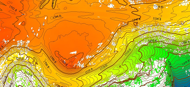
RTL-400 generated digital terrain model (DTM) overlaid with contour map. (Image: RedTail)
RedTail Lidar Systems is a division of 4D Tech Solutions Inc., a company focused on providing innovative technology-based solutions to address government and commercial customer needs. RedTail’s in-house technical expertise — coupled with a full suite of software and hardware design and manufacturing tools — allows the company to develop custom lidar solutions for manned and unmanned vehicle applications.
A point cloud is fundamentally a simple construct. It is a collection of points in 3D space, each point being given a coordinate in Cartesian convention. The points can also be given other properties, often these will be indicative of how they were obtained.
Examples might include the time at which they were “seen” by the surveying device that collected the data. The intensity or error in position that the point has might also be included.
Often point clouds will have around 100 million points after conducting a survey. Photography can also be overlaid on point clouds using photogrammetry techniques to essentially build 3D photography.
Image: OxTS
INS survey: point clouds
The principal method of collecting point-cloud data is by using lidar. Lidar technology is akin to radar: light is sent out from the device and bounces back off of objects. The difference is that radio uses large wavelength radio waves and lidar uses small wavelength lasers for high precision.
The time for light to return to the device is used with the speed of light to calculate the distance away. Typically, a lidar device will contain lasers with a fixed vertical angle, but which spin around in the horizontal plane. Internally, the device knows at what angle the laser is pointing vertically and its azimuth angle. This gives the device the position of the point on the object in 3D spherical coordinates.
The lasers inside produce thousands of points per second. Intensity, mentioned above, refers to the intensity of the reflected beam and indicates the reflectivity of the object.
What is a georeferenced point cloud?
Lidar requires navigation data to conduct a survey. We combine the navigation data with the lidar data to create georeferenced point clouds. Lidar devices know where points are in relation to each other, but they need to be told where they are in the world to be able to build a point cloud while moving the lidar.
The navigation data often comes from an inertial navigation system (INS). An INS is a sophisticated combiner of inertial measurement unit (IMU) and GNSS data to get the best navigation data — so a device knows where it is in the world and how it is moving.
The coordinates from the INS are added vectorially to the point coordinates of the lidar to get the final coordinates that would be used in the point cloud. This allows a user to put their lidar device on a vehicle like a van or an unmanned aerial vehicle (UAV) with an INS, to survey large areas efficiently instead of doing multiple static surveys and stitching them together.
Photo: OxTS
What are point clouds used for?
There are a wide range of applications for which point clouds can be used. They are increasingly used in real time for robots and autonomous driving computers to understand their environment and navigate through it. The data in a point clouds is convenient for recognizing and identifying surfaces and objects; for example, other cars, road signs and lane markings.
OxTS has been a global leader in inertial and GNSS technologies since 1998. OxTS is fundamentally involved in helping car manufacturers get the navigation data they require to go with lidar data in autonomous vehicle development, and in point clouds creation for use in surveying.
Distances and volumes are easy to calculate using point-cloud analysis software, and intensity can help identify different materials.
Another feature that lidar offers is multi-returns. This allows a laser pulse (which has a finite cross-section) to bounce back off of multiple surfaces to give multiple points from the same pulse. This is particularly useful for seeing windows and also seeing through them, and also for a myriad of other uses such as seeing the top of a treeline and the ground when flying over with a UAV.
It can also be used to see snow depth. The lidar can see the top layer of snow and also gets another strong return from the ground beneath.
At OxTS, we see lidar point clouds being used for driverless-car and work-vehicle development, coastal and forest management, infrastructure monitoring (signs, drains, bridges, road surfaces, railroads, etc.), creating 3D models of cities, pipeline exploration and more.
The final product is a simple file format, for which the possibilities are almost endless — and we see new applications using point clouds all the time.
Spirent Federal Systems has been awarded a contract to support anechoic chamber testing for a major U.S. military agency.
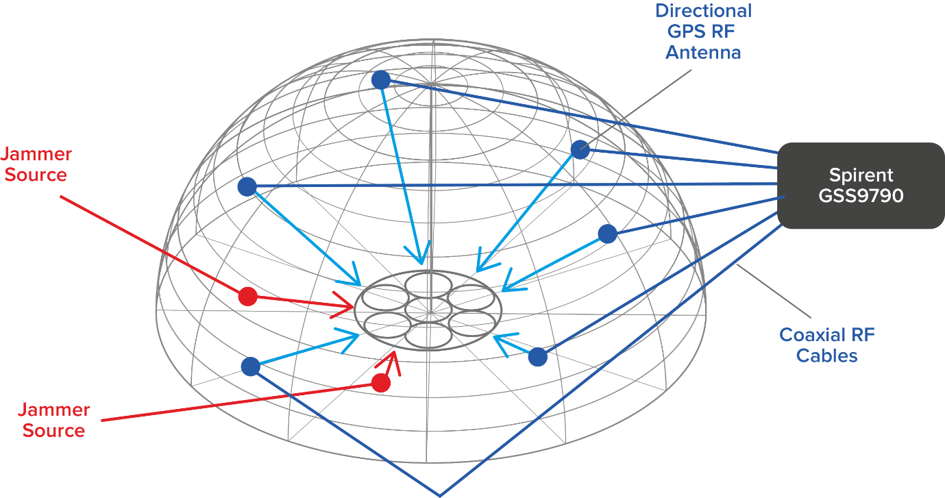
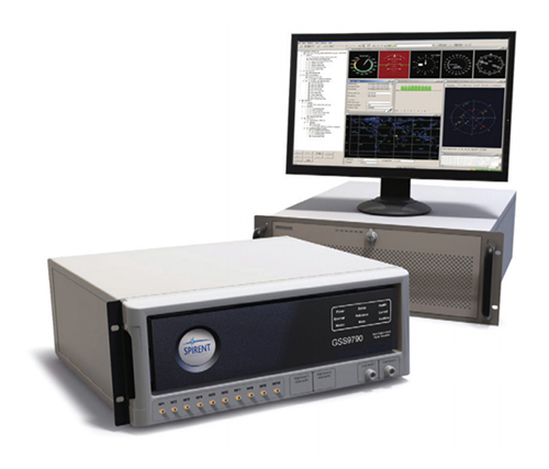
Spirent’s GSS9790 multi-output, multi-GNSS RF constellation wave-front simulator will be used as the signal generator attached to multiple transmission antennas for broadcast into the chambers.
Within this design, the antennas are structurally distributed to represent the correct arrival vectors of the simulated satellite signals on the device under test, creating the most realistic test environment possible. In addition, the GSS9790 supports interference sources located anywhere in the chamber to imitate different threat scenarios.
Image: Spirent
“Interference can threaten GNSS signals in multiple ways,” explained Jeff Martin, VP Sales. “We recognize the need for controlled, repeatable conditions to combat these threats. The GSS9790 delivers all the tools needed to successfully mitigate them.”
The GSS9790 simulator. (Photo: Spirent)
The Spirent GSS9790 supports classified Y-code, SAASM and M-code and can be found in key government labs across the country.
The Spirent GSS9790 enables verification of CRPA systems, spatial testing of single-antenna devices, and real-world-time-synchronized indoor GNSS implementations. The system is a development of the Spirent GSS9000. Combined with Spirent’s SimGEN software, it offers a powerful test platform for anti-jam and interference testing.
On Aug. 19, the U.S. Federal Communications Commission (FCC) granted a request for authorization from AT&T Services to use Galileo for emergency location purposes.
AT&T plans to use Galileo in conjunction with GPS to improve the accuracy of its E9-1-1 location services on mobile devices, and facilitate faster response from emergency services when wireless callers dial 9-1-1.
The request was approved by the FCC’s Public Safety and Homeland Security Bureau .
The FCC found that AT&T had satisfied the conditions for commercial mobile radio service (CMRS) providers to integrate foreign satellite signals into E9-1-1 services.
Under E9-1-1 requirements established in 2015, CMRS providers seeking to use foreign signals for E9-1-1 services must meet several conditions, including ensuring that integrating non-U.S. signals won’t cause interference with the E9-1-1 system.
Carriers also need to submit a signal integration plan including a mechanism to detect, mitigate and disable Galileo signals if they cause harmful interference.
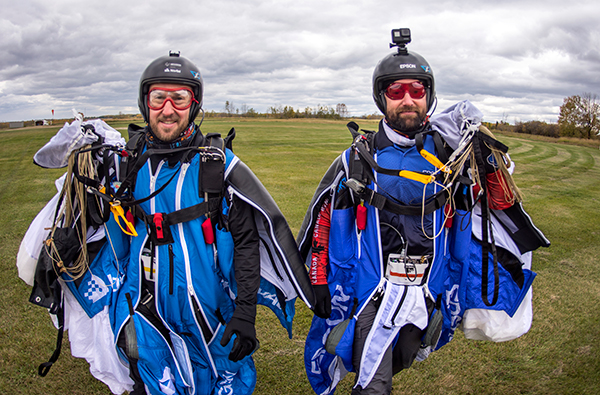
An applications engineer and his sky-jumping bud don wingsuits to test a NovAtel GNSS receiver integrated with an Epson IMU.
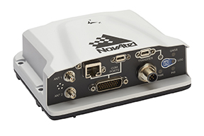
In September 2019, a specialized team assembled at an airstrip outside of Edmonton, Alberta, Canada. Their mission: Put the Hexagon | NovAtel PwrPak7D-E2 enclosed receiver through tricky test procedures that involved jumping out of an airplane at 10,000 feet.
Taking the NovAtel SPAN receiver to the skies was the brainchild of Andrew Levson, who is both a NovAtel engineer and a skydiving aficionado. He proposed using a wingsuit to test the receiver’s positioning accuracy.
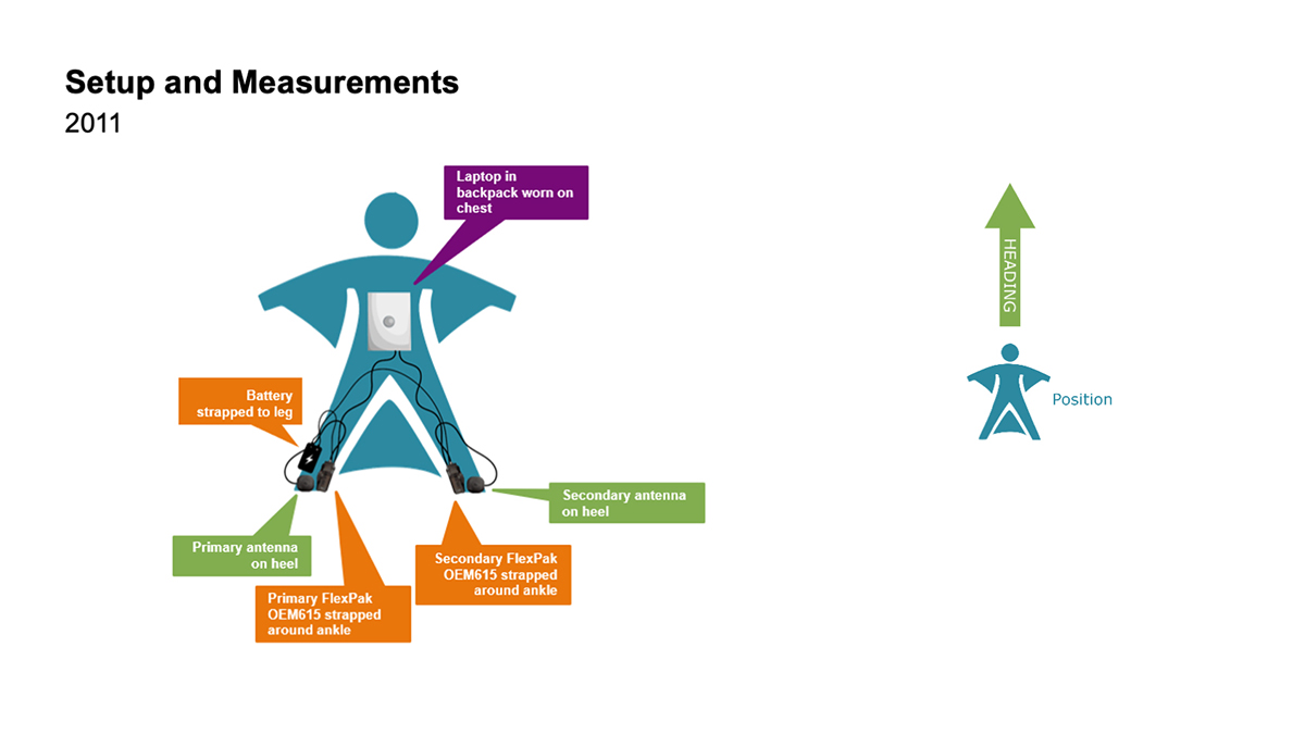
The first wingsuit dive took place in 2011, with NovAtel’s OEM615 receiver and ALIGN heading technology.
This time, the engineers aimed to test both NovAtel’s GNSS receiver featuring SPAN tightly coupled GNSS+INS functionality and its new companion, the Epson G370 inertial measurement unit (IMU). Both are packed in the PwrPak7D-E2 to provide uninterrupted positioning even in GNSS-denied environments.
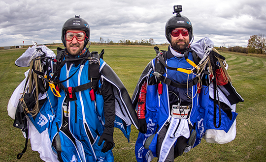
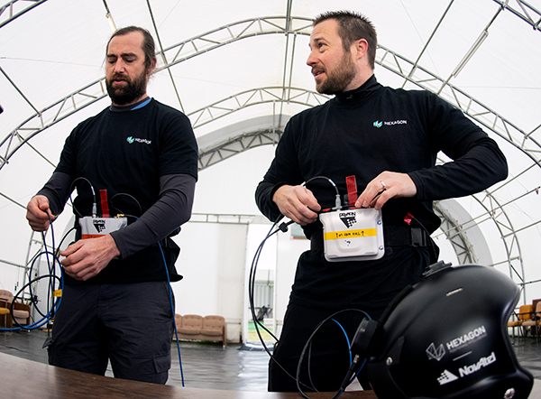
Wingsuit jumpers Andrew Levson (right) and Blair Egan suit up for the NovAtel tests. (Photo: NovAtel)
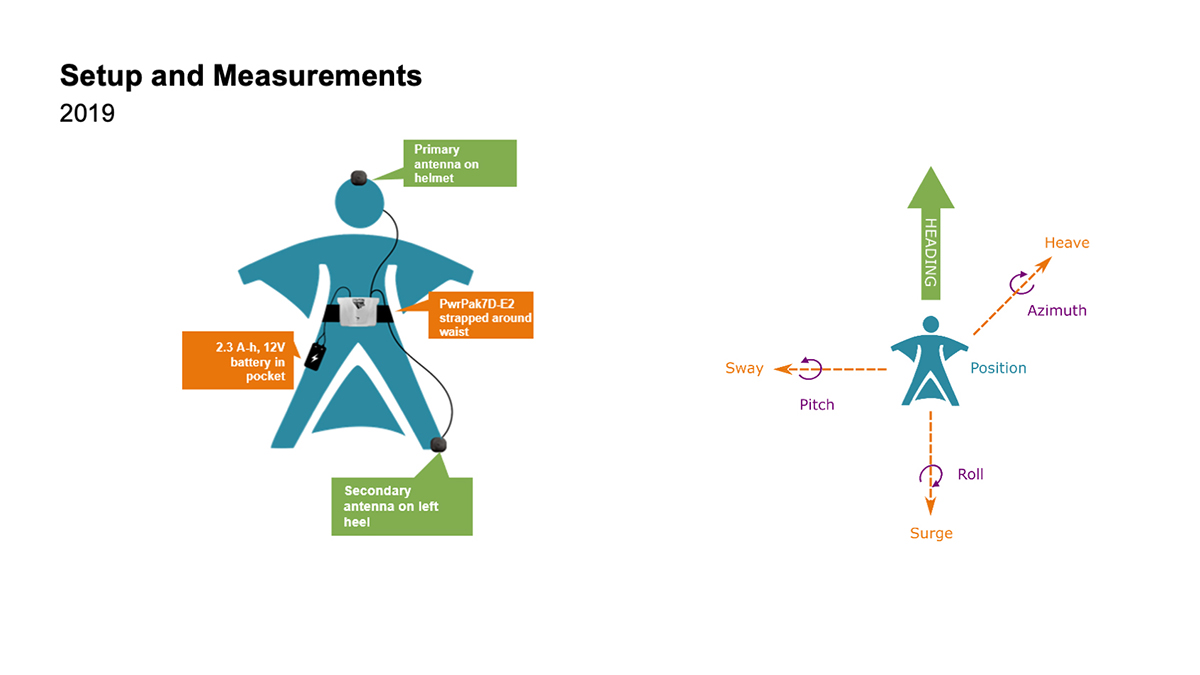
“We chose to revive the project, given that equipment has evolved with more comprehensive capabilities,” said Patrick Casiano, manager of Product Management and Applied Technology, NovAtel. “Between 2011 and 2019, we could significantly reduce the payload while increasing value in the data.” In 2011, NovAtel was only able to monitor Levson’s heading. In 2019, the team captured heading, azimuth, pitch and roll measurements.
“We wanted to prove that our equipment can work in a high-dynamic environment, which isn’t necessarily ideal conditions for collecting positioning data,” explained Kiera Fulton, associate product manager, Enclosures and Post-Processing Software, NovAtel. “By proving our products work in a less-than-ideal environment, we exemplify how robust our solutions are.”
Photo: NovAtel
Test Preparation
For the 2019 test, the team chose to gather attitude data. The team also asked Levson to perform specific skydiving maneuvers to rigorously test the positioning solution. “Rather than performing just a simple flight to the ground, we wanted to challenge the solution to reveal more,” Casiano said.
The test was not easy to implement. A lot of behind-the-scenes planning and preparation went into the project. Plus, unforeseen factors made the test more challenging, Fulton said, such as logistics and weather.
“The skydivers require specific weather conditions in order to jump safely,” Fulton said. “Considering how quickly the weather can change here in Alberta, the time windows in which the skydivers could safely jump were few and far between. We pulled through regardless of these adversities.”
When the day of the jump came, the skydivers jumped five times — as many jumps as the weather would permit. “Theoretically, one jump is enough,” Casiano explained. “But as engineers, we always want to have more data to work with.”
2011 wingsuit jump setup. (Image: NovAtel)Wingsuit Jumps Compared: Because of the PwrPak7D-E2’s small size yet strong processing power, Levson required fewer devices in 2019 than in 2011, when he was equipped with two receivers, two antennas, a laptop and a battery. The amount of positioning data also increased. (Image: NovAtel)
High-Flying Maneuvers
The skydivers executed four maneuvers during their jumps.
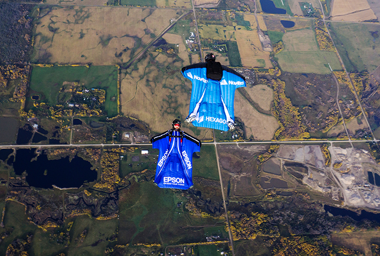
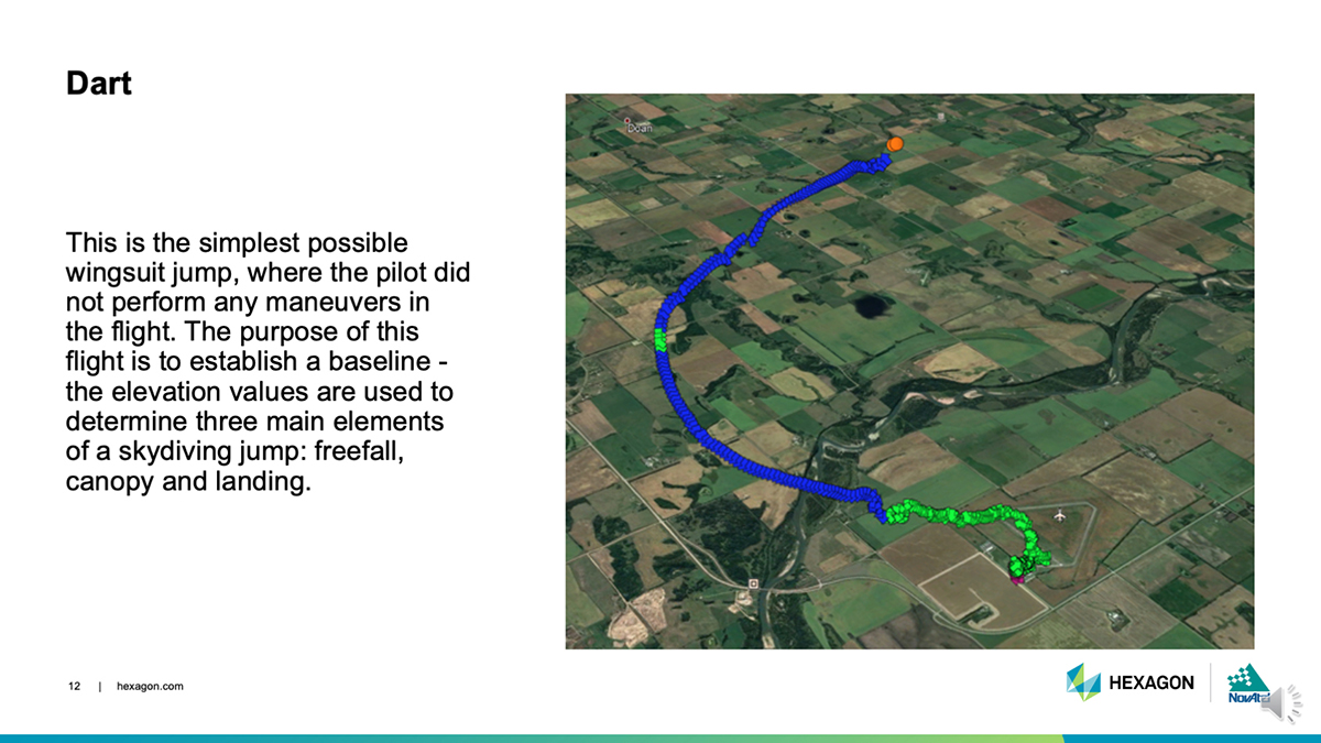
DART: This simple jump established a baseline for more complex maneuvers to follow. (Photo: NovAtel)
Dart. The skydivers first performed a straight jump, which the team called the Dart. The data from this jump provided a baseline for analyzing the positioning and attitude data.
“This was more important for the attitude analysis, as we have never collected inertial data in a skydiving jump before,” Fulton said.
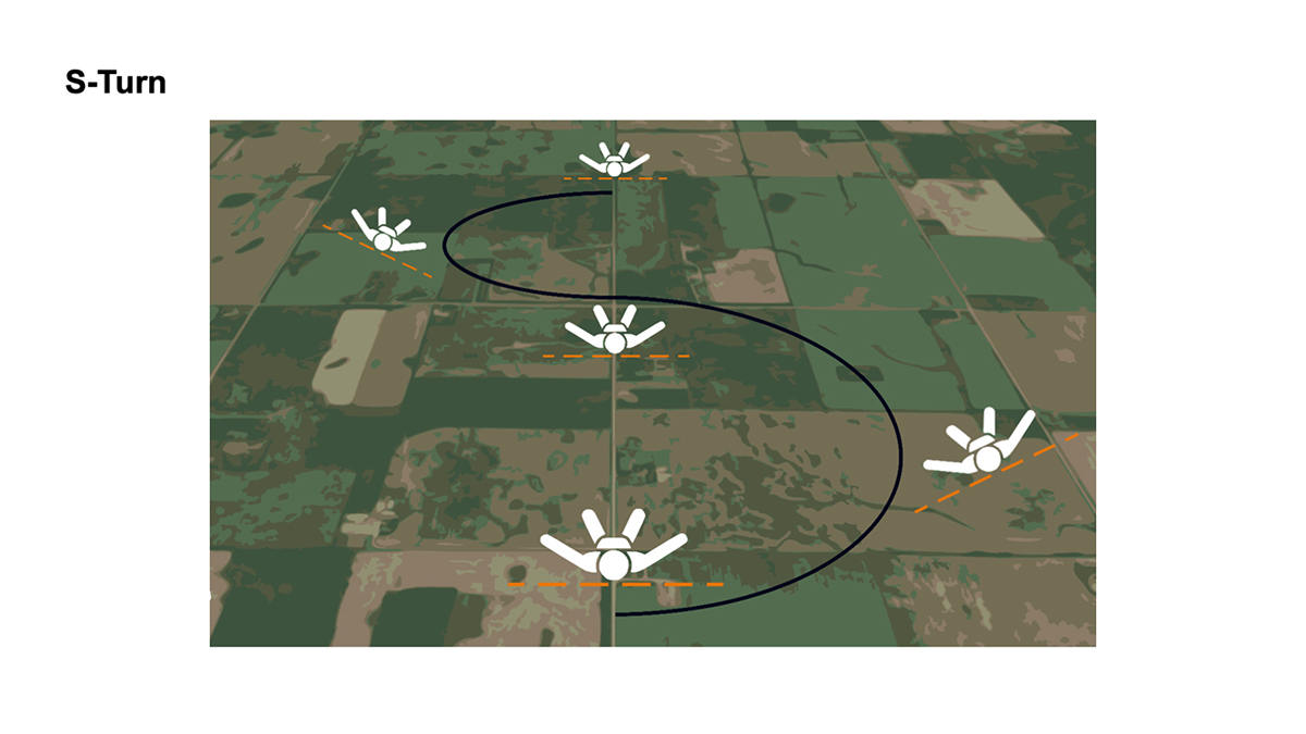
S-Turn: One of three completed maneuvers. (Image: NovAtel)
S-Turn. Next came the S-Turn. In this maneuver, Levson weaved from side-to-side to test how the equipment handles agile movements.
For the S-Turn, the engineers anticipated seeing the biggest changes in roll. “We were pleasantly surprised to see that the S-Turn is detectable in the azimuth data as well, indicating high correlation between roll and azimuth in a skydiver’s movements,” Fulton said.
The maneuver revealed that when Levson rolls, his body is using less surface area for wind resistance. As a result, he was falling to the ground faster, which then meant the dataset is shorter.
“This became another challenge during data processing, as the free-fall portion of the datasets were now becoming less than 3 minutes in duration,” Fulton said.
Data from the S-Turn also revealed the effect of crosswinds, which is detectable in the data.
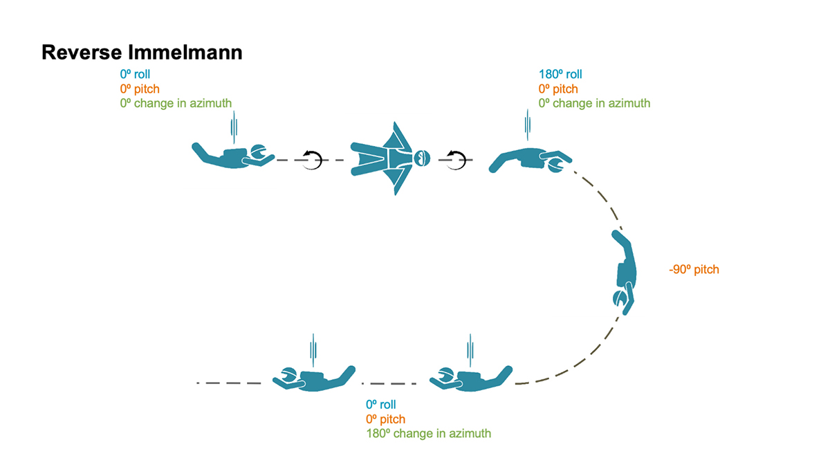
Reverse Immelmann: How the intricate maneuver works. (Image: NovAtel)
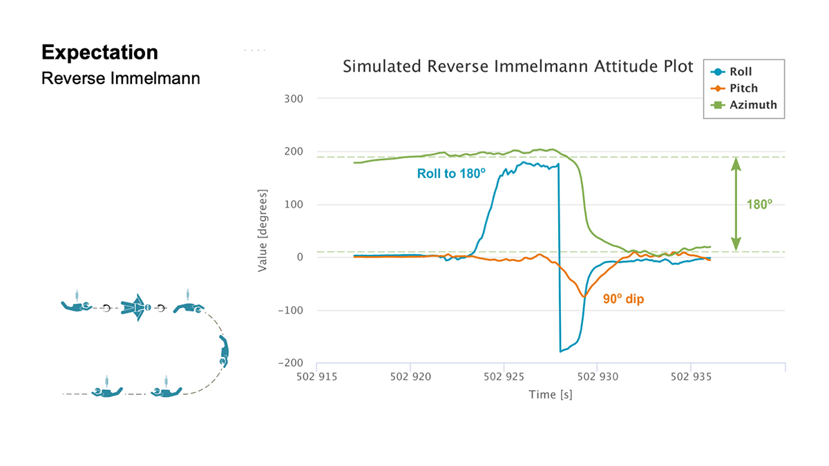
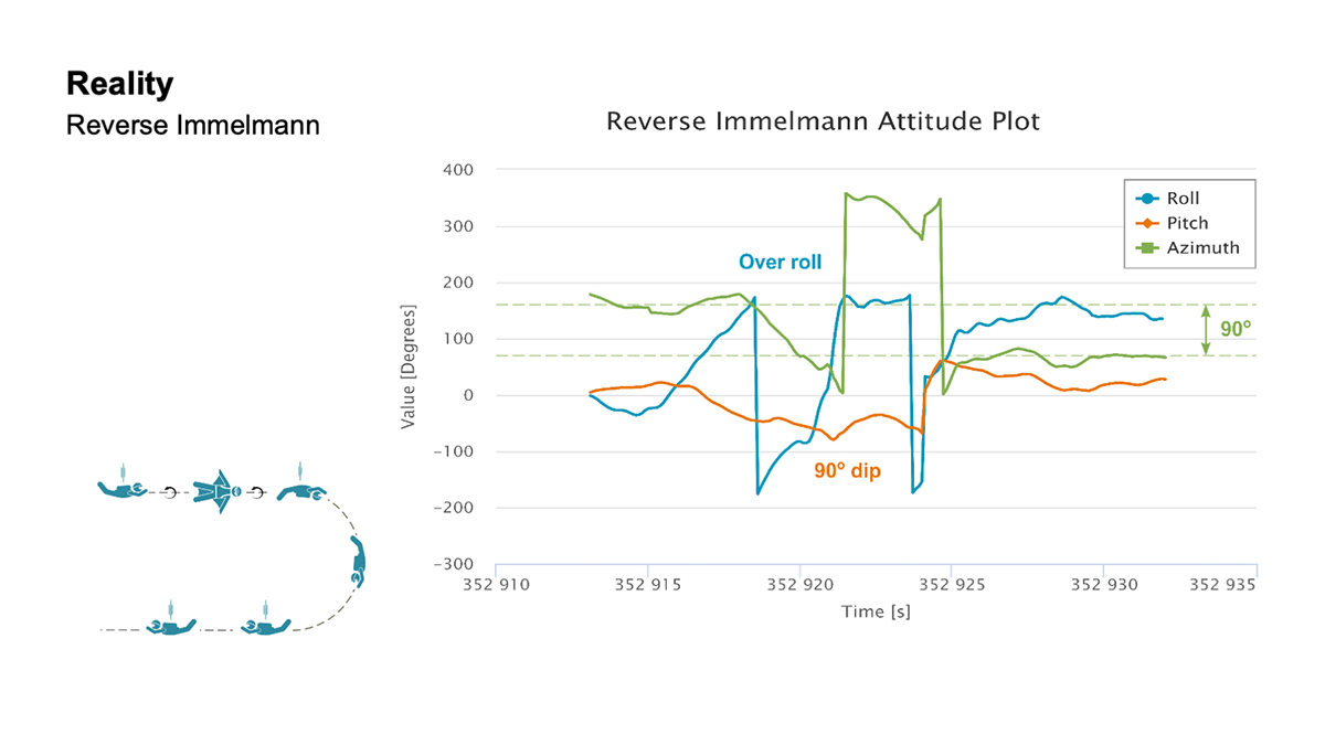
Reverse Immelmann. The third maneuver was the Reverse Immelmann. Levson flipped onto his back, began a downward turn until perpendicular to the ground, then leveled off, traveling in the opposite direction from where he began.
This complicated exercise provided data for all aspects of an attitude solution — roll, pitch and azimuth. By comparing the expected and real data, the team found several places where the maneuver wasn’t performed perfectly.
“There are many challenges once in the air that would have caused Levson to deviate from the trends in the data that we expected,” explained Fulton. “This is where we realized that our solution was working much more to evaluate the skydiver, rather than using the wingsuit to evaluate our product.”
Casiano agreed. “As a whole, the PwrPak7D-E2 was telling a story about Andrew’s flight,” he said.
The team also wanted to have the skydivers try a Cobra — a maneuver from aerobatics where an airplane momentarily lifts it nose and stalls — but time constraints prohibited it.
“If we had gotten this [a Cobra] recorded, it would have been detectable in the pitch and horizontal velocity data,” Fulton said. “Who knows what other findings we would have come across in this data!”
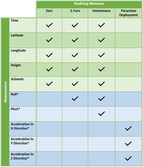
Measurement matrix: The asterisks (*) denote data values that can only be measured with an IMU. (Chart: NovAtel)
Applications
All these tests, of course, are designed to apply to real-world applications where the PwrPak7D-E2’s capabilities are used in dynamic environments.
For instance, an unmanned aerial vehicle (UAV) needs a feedback mechanism that tells the user whether it is moving or hovering. “In the wingsuit project, we proved that crosswind can be detected,” said Casiano. “This is an important finding for UAV applications, since a feedback loop from the PwrPak7 and the SPAN system can help rectify movement from external forces with counter propulsion to stay still. The PwrPak7D-E2 enclosures allow a data rate of up to 200 Hz, meaning you can capture motion with more detail.”
The PwrPak7D-E2 also works well for any black-box application where users want to record with the push of a button.
Inside the PwrPak7D-E2
Photo: NovAtel
The PwrPak7D-E2 is an all-in-one product. Its components are designed to work together seamlessly to provide positioning data, housed in NovAtel’s OEM7 firmware.
GNSS receiver card used to capture positioning data
Dual-antenna capability to provide accurate heading
Epson IMU to record attitude and motion
On-board logging to eliminate the need for constant monitoring on a PC
Post-Processing
Preparation enabled the team to process the data on site. The on-board logging feature on the PwrPak7D-E2 eliminated the need for constant monitoring during data collection. The unit is pre-configured so that at the time of the jump, Levson only needed to push a button for the unit to start collecting data.
Once the pair of skydivers landed, the ground team offloaded the data for processing, similar to using a memory stick, and moved it to a laptop computer.
“We pulled raw measurement data from the receiver and processed those measurements into position and attitude information,” Fulton said.
It took about 30 minutes to determine whether the dataset was viable. Later processing back in the office generated the charts such as those below.
Expectation: For both the S-Turn and Reverse Immelman maneuvers, a simulated plot was generated at the office to better understand the inertial data produced from the actual wingsuit jumps. (Chart: NovAtel)Reality: This chart shows the actual data. (Chart: NovAatel)
Dynamic Environments
Photo: NovAtel
The PwrPak7 series can be used in many environments in the automotive, agriculture, marine, defense and UAV fields.
“We are constantly trying to find ways to apply this product to other applications and industries,” Fulton said. “With more testing, we keep finding that the PwrPak7 can be used to solve more challenges.
“We want to push the boundaries of our products. True innovation comes from challenging yourself and hovering outside your comfort zone,” Fulton said. “For this project, we are more than satisfied with the results we found. In order to further challenge ourselves and this product, we look forward to applying the PwrPak7 in more scenarios.”
“The PwrPak7 is a robust unit that sets us up for more exploration,” Casiano said. “We are always looking for more challenges to put this unit through to see how the PwrPak7 can further help solve our customer’s problems.
But will there be more skydiving for NovAtel in Levson’s future?
“We could always revisit the skydiving project in another nine years,” Casiano said. “But who knows how the technology will evolve by then?”
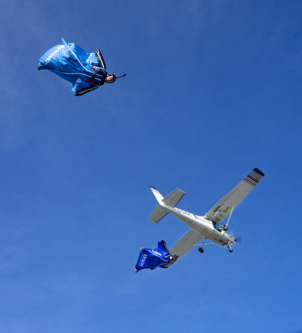
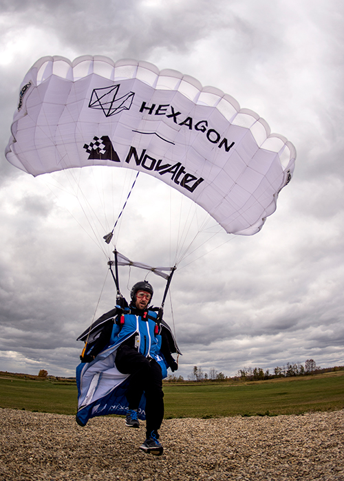
Post flight: Blair Egan (right) and Andrew Levson back on Earth. (Photo: NovAtel)
What it feels like to take the plunge
For those of us who have never jumped out of a plane, engineer and skydiver Andrew Levson provides insight.
“It’s not as scary as people think. Because the plane is moving fast, it’s mostly just windy and loud. You don’t get that roller coaster type feeling; in fact you don’t feel like you are even falling — freefall feels more like floating than falling. You definitely wouldn’t know you are flying at speeds over 100 mph.
“When you are climbing out of a plane, there is nothing else on your mind aside from the jump you are about to do. It is pure freedom, and there is often no stress, just a sense of peace and an intense focus on your plan for the jump. Once you get out of the aircraft, you get to fly your body in the way that you want to — most people only know of the position of falling with your body arched and belly toward the ground, but there are many different ways you can orient your body. Some of the lesser known ways to fly your body include your arms and legs spread out while flying a wingsuit (with your belly or back toward the earth) or flying with your head pointing straight at the ground.
“When you skydive, you get to explore the sky with your friends, which is an amazing and unique experience. During a skydive, it is common to experience an ultra-focus during the jump — time slows down a bit and you can see and feel things that are seemingly beyond your typical capability.Many people are amazed at how much skydivers are able to do in the short period of time that a single skydive lasts — about a minute for regular skydives and about two or three minutes when flying a wingsuit.”
The Federal Aviation Administration (FAA) plans to evaluate technologies and systems that could detect and mitigate potential safety risks posed by unmanned aircraft. The effort will be a part of the agency’s Airport Unmanned Aircraft Systems Detection and Mitigation Research Program.
The FAA Reauthorization Act of 2018 requires the agency to ensure that technologies used to detect or mitigate potential risks posed by unmanned aircraft do not interfere with safe airport operations.
The FAA plans to test and evaluate at least 10 technologies or systems. The evaluations are expected to begin later this year and will initially occur at the FAA’s William J. Hughes Technical Center, located next to the Atlantic City International Airport in New Jersey.
After the initial testing and evaluation in New Jersey, the agency expects to expand the effort to four additional U.S. airports. Those selections will be made at a later date.
According to the FAA, interested manufacturers, vendors and integrators of drone detection and/or mitigation technologies/systems will have 45 days to respond to its announcement.
In addition, the FAA expects to issue another solicitation in the coming weeks for airport operators interested in hosting the additional research and testing.
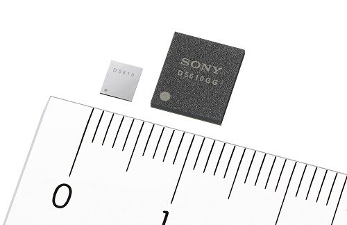
Sony GNSS receivers. (left) CXD5610GF, (right) CXD5610GG. (Image: Sony)
Sony Corporation plans to release a high-precision GNSS receiver for use in internet of things (IoT) and wearable devices. The new receivers have low power consumption for dual-band positioning operation — as little as 9 mW.
Increasing use of IoT and wearable devices that utilize location information has resulted in growing demand for GNSS receiver large-scale integrated circuits (LSIs). Precise positioning and reliable communications must be ensured to maintain proper operation of IoT and wearable devices, which are being used even in difficult communication environments and unstable conditions, such as multipath propagation situations caused by reflection off the ground or nearby buildings or the effects of the swinging of the arms when attached to a person’s wrist.
Additionally, device size constraints necessitate a compact battery, whereas satellite signal reception and positioning when using GNSS functionality typically consumes a lot of power, resulting in poor battery life.
The new LSIs support not only the conventional L1 band reception, but also L5 band reception, which is currently being expanded across GNSS constellations, thereby making them capable of dual-band positioning. Sony’s original algorithms enable stable, high-precision positioning even under the difficult conditions unique to wearable devices.
Also, the use of Sony’s original high-frequency analog circuit technology and digital processing technology delivers low power consumption during continuous positioning for dual-band reception operation.
The new LSIs will drive greater opportunities to develop new products and services such as smartwatches and other wearable devices that cannot use external power supplies, as well as IoT devices used for applications such as trackers. They also show promise in a wide variety of applications which require precise positioning and stable communications, such as automotive services.
High-precision, stable positioning via dual-band operation
Compared with the L1 band, the new signal method used in the L5 band employs signal units that are 10 times narrower to measure the range between the GNSS satellite and receiver, improving positioning precision and amplifying the transmission power from the satellite, resulting in high-precision, high-sensitivity positioning.
Quick, accurate GNSS signal reception via Sony’s original algorithms enables positioning that is more stable than conventional products even in changing reception environments, such as obstructing from buildings when on the move and acceleration of wearables due to swinging of the arms. This also leads to quick positioning time even from cold starts, which require more time.
Additionally, Sony’s original digital signal processing technology enables countermeasures against the performance degradation caused by radio interference from aircraft communications as well as spoofing attacks and other issues, thereby improving resistance to interference.
Low power consumption and high sensitivity are delivered by Sony’s original analog circuit technology, which enables low-voltage operation, as well as digital circuits and software algorithms that enable software processing via low clock frequencies. This innovative design keeps power consumption to only 9 mW, the lowest in the industry, when simultaneously receiving signals in both the L1 and L5 bands.
Built-in memory
The new LSI’s feature built-in non-volatile memory for storing firmware, etc. This design makes it possible to update the firmware without adding externally mounted memory and contributes to a more compact design for IoT and wearable devices by saving space. It also makes it possible to complete data-processing in the products, resulting in low power consumption and improved access speed.
Key specifications
Power Consumption
1.5 GHz/1.2 GHz simultaneous reception
9 mW
11 mW
1.5 GHz reception
6 mW
7 mW
1.2 GHz reception
7 mW
8 mW
Hot Start Sensitivity: –163dBm
Tracking Sensitivity: –167dBm
Hot Start Initial Positioning Calculation Time: Less than 1 second (at -130dBm)
User Interface: UART, I2C, SPI
Package: XFBGA 54 pin, LFBGA 72 pin
External Dimensions (LWH): 3.2×3.7×0.5 mm; 7.0×8.0×1.4 mm
Huber+Suhner extends its Sencity rail MIMO antenna portfolio with dual-band GNSS services
Huber+Suhner, an international manufacturer of components and systems for optical and electrical connectivity solutions, has extended the capabilities of its rail rooftop antennas with its launch of an embedded dual-band GNSS antenna that meets the railway industries’ stringent requirements.
Adding to its established Sencity rail antenna portfolio, the new multiple-input, multiple-output (MIMO) rooftop antenna enables railway operators to improve geospatial positioning and time precision of their operations.
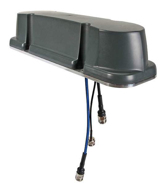
Photo: Huber+Suhner
Supporting both the upper and lower GNSS bands, the antenna enables pinpoint location accuracy for the rigorous applications such as autonomous trains. With greater transparency of movement on the tracks, railway operators can improve the operational planning of densely crowded railway tracks and metro lines.
“The GNSS port on the antenna supports a higher number of satellite constellations,” said Daniel Montagnese, Huber+Suhner product manager for railway antennas. “This enables operators to improve signal acquisition time, as well as reducing the impact of obstructions in order to increase efficiency on the tracks.”
The GNSS port is complemented by two broadband cellular and Wi-Fi compatible ports that can be deployed for a variety of different train-to-ground services.
The Sencity MIMO rail antenna supports the GPS, Galileo, BeiDou and GLONASS constellations. Its robust design also meets the stringent EN 50155 railway standard and is fire retardant according to EN 45545-2 and NFPA130.
Huber+Suhner is a global company with headquarters in Switzerland which develops and manufactures components and system solutions for electrical and optical connectivity. With cables, connectors and systems — developed from the three core technologies of radio frequency, fiber optics and low frequency — the company serves customers in the communication, transportation and industrial sectors.
While connected cars provide wonderful advantages, their integration with cloud connectivity come with a heightened risk for cyber attacks.
Commentary by Alexander Meisel
When it comes to connected cars, automakers are innovating fast. Consumers are experiencing increasing amounts of futuristic features, be they passenger connectivity, automated speed regulation or autonomous driving capabilities.
However, these innovations and their integration with cloud connectivity come with a heightened risk for cyber attacks. A recent study conducted by U.K. self-driving hub organization Zenzic found that becoming cyber-resilient will be the biggest technical obstacle to successfully deploy self-driving cars on roads by 2030. This mountain will be a big one to surmount, and it’s only growing in size: The auto industry has seen a 94% year-over-year increase in hacks since 2016.
How can automakers prioritize security while keeping up with the demand for innovation in today’s connected cars?
Carmakers must consider security from day one
To make sure that security is built into the very foundations of a car, automakers must make it a priority from the first day of design. This focus is lacking amongst carmakers at the moment. In fact, 19% respondents to one survey said they don’t do enough security testing in the design phase, and only 28% said that they do a lot of the testing during the design stage.
Automakers can use design principles to build in security from the outset. For example, the principle of complete mediation allows for enhanced security as it ensures that a software stem “requires access checks to an object each time a subject requests access.” This means that attackers are only invited to exploit a system on one single occasion due to checks on subjects’ permissions.
Carmakers can also ensure that they are not sacrificing security by considering its importance when purchasing components from separate suppliers. These components must be specific enough to enable security in the system, but generic enough to allow for innovation.
Automakers must make cybersecurity a priority from the first day of design.
Here, companies can leverage the software engineering principle of interface segregation. This means that a shrunken, clear interface should be supplied by the vendor, so that the customer only uses the methods that are of interest to them.
In turn, this allows systems to remain decoupled and thus easier to then build a rich interface on top of. However, carmakers will have to stay on top of the security of the part in the development phase, and ensure that dormant functions are not abused by at least logging their execution once somebody tries to call them out of context.
Developers and cybersecurity experts must become a core part of the team
Software development is relatively new territory for carmakers. Now, cybersecurity is a key component of building connected cars, and automakers need to embrace developers that have expertise in this area and make them part of the core team.
This cultural change must be championed by the business leaders to allow car security to advance alongside the innovative features that the industry is building. This can be done by implementing DevSecOps ideology into the team, in order to “build the mindset that everyone is responsible for security.”
Car development teams will likely need a group of cybersecurity experts who can educate the rest of the developers and are willing to participate in the development process in order to check and implement safe and secure functions. If a company doesn’t have this kind of expertise in-house, they can partner with an expert third-party to help them along this journey.
Innovation and security can complement each other
Cybersecurity doesn’t mean sacrificing feature innovation: developments are being made in the field of security too, such as biometric technologies that can be integrated into car design.
For example, Blackberry’s QNX technology “has built in concepts for hardware and software trust validation, hypervisor to maintain a separation between the safety critical and infotainment systems, and a core operating system which passes all the functional safety standards,” according to the company’s senior VP SVP, head of QNX, John Wall. Innovation need not suffer at the hands of security, and vice-versa.
Potential AV thieves would first look to use GPS data to disable or falsify a car’s GPS system, making it untraceable.
In addition, the world’s leading electric vehicle provider, Tesla, ensures security in its cutting-edge, connected cars by sending security updates to cars’ operating systems overnight, and even providing awards for hackers that manage to hack its cars.
Looking ahead to the possibilities of autonomous vehicles (AV) that can drive passengers without needing to have their owner inside, innovation in GPS will be necessary to ensure security and accountability of the car. Potential AV thieves would first look to use GPS data to disable or falsify a car’s GPS system, making it untraceable.
However, carmakers can make this impossible for hackers by not just logging the data in its raw form, but also combining it with other car data using cryptographic algorithms. This ensures that the GPS data remains traceable even after the hardware has been taken apart and sold on the auto-parts black market. In this way, the signature of the original data combined with the GPS position adds an additional layer of security.
Integrating security into connected car design is no simple feat, but it’s a necessary one for carmakers that want to ensure the safety of their passengers while on the roads. By using design principles, diversifying expertise within development teams, and understanding that security and innovation need not be a trade-off, they can do just that.
Alexander Meisel is an automotive cybersecurity engineer at intive. He has a computer networking diploma from Hochschule Furtwangen University, and he has served as a CTO and Development Team Director in previous companies. He has experience with venture capital, successful M&As, and product and technical marketing strategies. He is also a public speaker at technical conferences and trade shows.
A roundup of recent products in the GNSS and inertial positioning industry from the September 2020 issue of GPS World magazine.
OEM
Inertial sensors
Includes four models
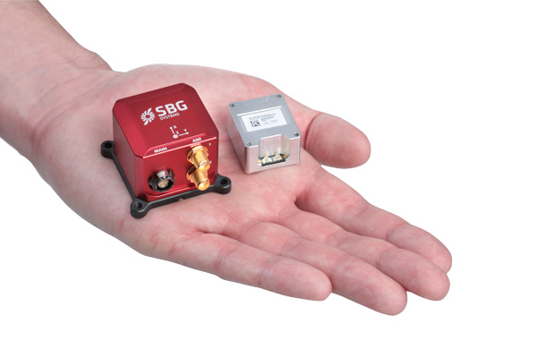
Photo: SGB Systems
The third-generation Ellipse series has a 64-bit architecture, allowing high-precision signal processing. All of the INS/GNSS devices now embed a dual-frequency, quad-constellation GNSS receiver for centimetric position and higher orientation accuracy. The Ellipse-A is a motion sensor; Ellipse-E provides navigation with an external GNSS receiver; Ellipse-N is a single-antenna RTK GNSS/INS; and Ellipse-D is a dual-antenna RTK GNSS/INS. With its new 64-bit architecture, the third-generation Ellipse series enables the use of high-precision algorithms and technology used in high-end inertial systems such as rejection filters and FIR filtering.
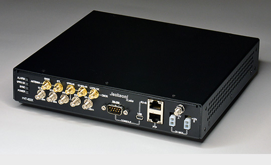
The PNT-6220 Assured Reference combines low-Earth-orbit (LEO) signals, GNSS, terrestrial, wireline and atomic clock services in one small solution for critical infrastructure applications. The PNT-6220 seamlessly combines concurrent L1, L2, L3 and L5 GNSS reception with a LEO-based Satellite Time and Location (STL) timing receiver. It also includes terrestrial receivers and PTP/IEEE-1588 edge grandmaster and PTP/IEEE-1588-slave capability. It provides assured PNT for critical infrastructure applications such as those described in the directives of Presidential Executive Order 13905. It can serve as a timing reference for 5G equipment, an ePRTC-capable reference, or a high-performance disciplined reference that supports PTP/IEEE-1588, STL, RF distribution and multi-frequency GNSS capability. The PNT-6220 can automatically select the most optimal UTC reference input and switch over among its numerous reference inputs if one or more are jammed or spoofed, as well as average several references for additional stability and accuracy.
Jackson Labs Technologies, jackson-labs.com
GNSS Receiver
Integrates correction service
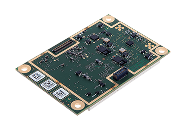
Photo: Septentrio
The AsteRx-m2 Sx OEM board provides a GPS/GNSS receiver with always-on sub-decimeter accuracy without the need for additional correction service subscriptions. GNSS corrections are automatically streamed to the receiver. The integration enables plug-and-play positioning with high accuracy available out of the box. The AsteRx-m2 Sx is an efficient positioning solution for small robots, aerial drones and automation applications. Advanced anti-jamming technology AIM+ ensures robust and reliable operation in challenging environments, even in the presence of RF interference.
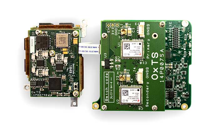
The xOEM v3 inertial navigation system includes the architecture from the company’s IP65-encased xNAV v3 as well as a full range of software interfaces, providing integrators maximum configuration flexibility, real-time monitoring, post-processing and analysis. Software interfaces can be customized using the OxTS NAVsuite. Plugins can be created using the company’s NAVsdk, allowing the xOEM v3’s software to be easily packaged and included as part of a product.The high-grade MEMS inertial sensors and real-time kinematic (RTK)-capable GNSS receiver within the xOEM v3 board set deliver high performance capabilities. The board set provides 0.1° heading accuracy, 0.05° pitch/roll accuracy and 2 cm global position accuracy. The board set is compact at 150 grams, which enables manufacturers to seamlessly integrate and build a high-performance INS into their products, such as commercial mapping applications on land and in the air. Its light weight means more payload capacity for other critical components. An add-on lidar georeferencing software package is also available with a sophisticated boresight calibration tool.
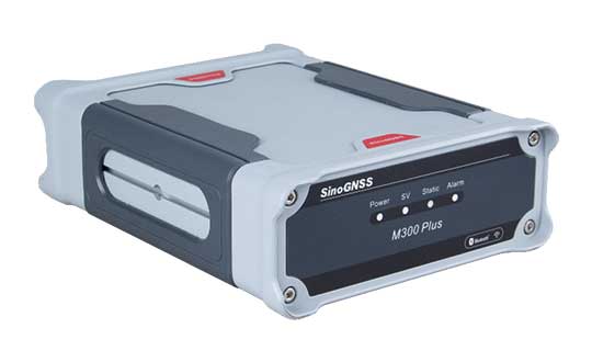
The M300 Plus GNSS receiver is designed to supplement the company’s M300 Pro, which is aimed at clients who need a more economical version for their CORS networks. The M300 Plus is also designed for monitoring projects and other applications. By using a powerful, adaptive detecting and canceling technology, the M300 Plus provides enhanced anti-jamming capability, which is critical for a reference station providing reliable GNSS data. Its built-in web server provides remote control of receiver configuration, status, firmware update and data download. It uses a 4G module as an internet backup, enhancing the stability of data connections.
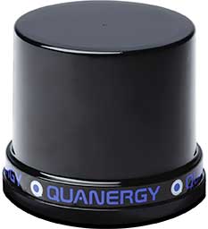
The MQ-8 family — 3D lidar sensors and perception software — are part of Quanergy’s Flow Management platform. Designed with a new smart beam configuration, the MQ-8 solution delivers up to 140 meters of continuous tracking range, enabling up to 15,000 m2 of coverage with a single sensor. It is suitable for flow management applications such as security, smart city, social distancing and smart space industries.
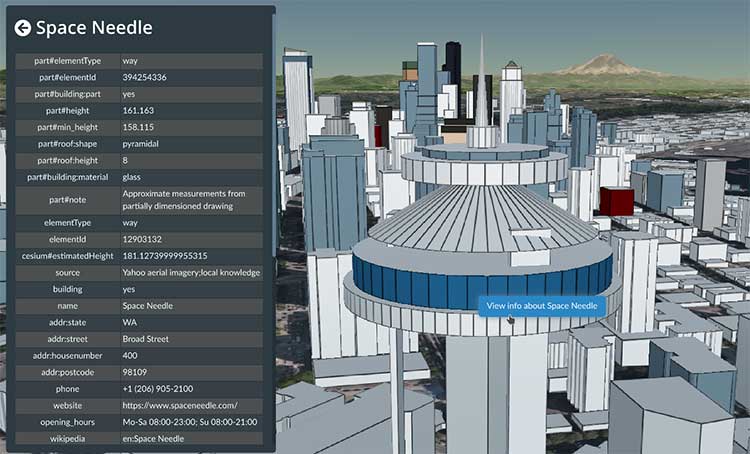
Cesium OSM Buildings expands the company’s suite of Global Base Layers including worldwide terrain, aerial imagery and streetmaps already available. With the new layer, 3D buildings can be visualized, styled and analyzed in an efficient and interoperable manner using 3D Tiles, the open standard developed by Cesium to stream massive 3D geospatial datasets. The layer gives geospatial developers urban context to 3D applications. The buildings are created for efficient visualization and are streamable to any device with 3D Tiles.Cesium OSM Buildings are derived from OpenStreetMap. Buildings are also regularly updated, firmly clamped to terrain, and individually selectable and styleable.
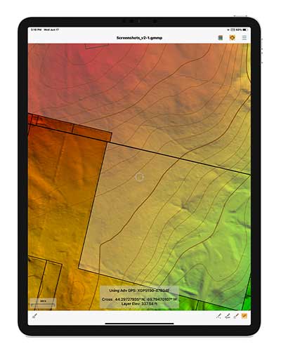
Version 2.1 of Global Mapper Mobile provides updates to both the free and Pro versions. The iOS and Android applications are designed for viewing and collecting GIS data, and provide situational awareness and location intelligence for remote mapping projects. A complement to the desktop version, the mobile app can display all supported vector, raster and elevation data formats. The release improves vector feature styling, terrain layer support and layer transparency setting. In the Pro version, it introduces advanced GPS support, allowing users to connect to external, high-accuracy Bluetooth GPS devices from vendors such as Eos Positioning and Bad Elf. It also allows access to detailed information including the satellite constellation, precise location information and the raw NMEA stream.
The AiRXOS Enterprise Energy Solution provides digital compliance, situational awareness of airspace and assets, inspection, emergency response/disaster recovery capabilities, analytics and asset performance tools in a connected platform. It runs on AiRXOS’ Air Mobility Platform — a secure, cloud-based, extensible platform that enables integration of an energy organization’s current applications and other UAS service suppliers. It brings all UAS lifecycle operations into one view, including infrastructure inspection, asset and crew management, and emergency operations after a natural disaster.
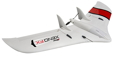
The Xeno FX is a fixed-wing platform optimized for efficient and cost-effective area survey and monitoring missions. Users can program the flight plan before launch to ensure thorough coverage of a target region. The fixed-wing design allows for efficient cruise and maximum time aloft. The Safe Launch protective feature means the propeller starts spinning only after the airframe has been safely hand launched. A quick-change modular payload system allows users to reconfigure their data-acquisition hardware for multiple missions. Constructed of Multiplex’s resilient Elapor foam, the folding wings make for compact storage and easy transport.
Congatec is offering a workload consolidation kit for vision-based situational awareness applications such as machine control and vision-based collaborative robotics.
The kit qualifies as an Intel internet of things (IoT) ready-for-production kit. It offers three virtual machines based on the hypervisor technology from Real-Time Systems.
One runs a vision-based artificial intelligence application based on the Intel OpenVino situational awareness software. The second is real-time capable and operates deterministic control software, and the third acts as an industrial IoT/Industry 4.0 gateway.