Esri has made available an interactive map of Ukraine that explores the events, locations and differences in languages in Crimea and Ukraine.
Blog
-
Esri Interactive Map Provides Geographic Look at Ukraine and Crimea
-
GIS in the Cloud
Geospatial Capability Without the Heavy Overhead

In the early 1990s, when I was the GIS manager for the Atlanta Regional Commission, I saw many counties and municipalities get into financial and political trouble by jumping into expensive “Cadillac” GIS operations without understanding the pitfalls. Occasionally the euphoria of the cutting-edge technology gave way to panic, as some local governments lost their GIS managers to fatter paychecks, leaving a GIS that no one could operate. That’s why I recommended that GIS newbies take baby steps first, starting with simple low-cost systems such as ArcView I and II fed with free GIS data from state or federal agencies. As their experience and comfort level grew, they could then ease into six-figure GIS operations with full aerial imagery collects. Although, to a lesser extent, the same pitfall still exists today.
A somewhat analogous situation existed in the early days of the Internet with organizations wanting their own websites. To have a website, an organization had to hire or have in-house HTML programming talent. The process was slow and expensive, and changes to the website could only be made by the HTML programmers. Today, numerous services such as www.wix.com or www.web.com permit anyone to build and update their own websites in the cloud without HTML experience.
The same kind of capability was needed for geospatial applications. ESRI, Intergraph, TerraGo, Google and others have provided online geospatial tools, but not the kind of environment that would encourage mass adoption. Digital Map Products, Inc., of Irvine, California, sort of backed into the vacuum with several web service solutions (LandVision, GovClarity and CommunityView) that embed GIS functions into real-world workflows to deliver geospatial capabilities for non-GIS professionals.
These services grew out of years of experience in the geospatial data business. In 1990, DMP started work as a data collector and integrator of parcel-level data. DMP developed public-private partnerships with county governments to continually update and share this valuable GIS data with a variety of public and private users. As a result, it now maintains one of the largest nationwide parcel boundary databases available. From these beginnings, DMP started creating applications around the data and deploying them through the Internet for the real-estate industry and local governments. DMP products became an authoritative and continuously updated source of parcel data that was quickly adopted by many counties, municipalities, home builders, commercial brokers, utilities and even some federal agencies.
Experience with cloud-based geospatial delivery services such as LandVision caused DMP to realize that it had a potentially powerful capability that could be expanded to meet broader local government needs. This led to the development of an entirely new generation of services, GovClarity and CommunityView, which drilled even deeper into the day-to-day work processes needed by governments. These two cloud-based services provide GIS capabilities that could only be matched by a strong in-house GIS team with considerable hardware and software support. GovClarity provides enterprise GIS tools and capabilities to municipal employees, while CommunityView improves public service by providing map-based query tools and information open to all public users.
Talking with several users of the three services, I learned that GovClarity and CommunityView are seeing increased adoption by local governments. Just like current website publication services, the DMP cloud-based services are providing GIS capabilities to customers without the headaches and expense of maintaining their own in-house GIS team. DMP does the heavy lifting by combining established geospatial services such as Bing and Pictometry, overlaying locally produced data, and then delivering the total package with custom-designed interfaces. The service, delivered through the local government’s website, is designed to be intuitive even by non-GIS staff members and constituents.
The City of San Juan Capistrano, California, is a good example that you can view for yourself. The site integrates Bing ortho imagery with street centerline data, and parcels and links to oblique views from Pictometry. There are numerous local data layers such as tracts, neighborhood associations, trash pick-up, hiking trails, and many others. The interface is limited but very easy to navigate for non-GIS users.
A nice feature is linked videoclips of their trails so a user can do a virtual walk/ride through in preparation for actual use (see image below).

For those who want to extend the capabilities of GovClarity and CommunityView, DMP provides API access to its underlying platform for further customization. There is even a capability to connect GovClarity to ArcGIS to leverage all GIS assets within the organization.
Talking with San Juan Capistrano’s City Engineer, Ziad Mazboudi, PE, about his experience with GovClarity and CommunityView, he cited several uses and benefits that the city experienced. GovClarity is being used as a GIS viewing and analysis platform by all departments without the need for separate GIS software or dedicated GIS staff. Users can view imagery and city data, do measurements, and update both feature and attribute data. The city has one GIS technician who builds local data layers that are uploaded to DMP for inclusion in GovClarity and CommunityView. Additionally, use of both ortho and oblique imagery with change detection has proved to be a powerful tool for code enforcement. As you can imagine, GovClarity is also a strong visualization environment for commission and public meetings. They project maps, ortho and oblique imagery on a big screen as an interactive viewing environment so everyone can see and quickly comprehend the issues being discussed.
CommunityView is the city’s public access site. The city has terminals at the front counters of many public offices that permit citizens to view and print maps and imagery. This has significantly reduced the time and difficulty answering questions and responding to the public. The same site is available 24/7 through home computers, and has resulted in strong customer satisfaction.
Many large counties have sophisticated geospatial operations, but the bottom line being the bottom line, those kinds of systems are not always practical for small municipalities and agencies. Ziad was pleased to report that building the city’s geospatial capability using a traditional in-house GIS department would have cost four to five times as much as the DMP cloud service.
Does DMP have a perfect solution? I don’t know, but time will tell. A downside is the need to maintain Internet connectivity, but DMP is working to build a work-around by caching data locally for limited periods of time in its mobile and tablet-based applications. DMP may or may not be a perfect solution, but the company seems to have hit a sweet spot with local governments and other clients by meeting their needs with a low-cost, low-risk and easy-to-use option. I believe DMP is worth your serious consideration.
R/Art
P.S. I’m going to attend GEOINT in Tampa next month. If you see me, please stop and say hello. I enjoy meeting my readers.
-
Comment Period on Pre-Operational CNAV Message Opens
A Federal Register Notice has been published allowing for a 30-day comment period on the proposed CNAV message on L2C and L5. The notice seeks comment from the public and industry regarding plans by the U.S. Air Force to broadcast pre-operational L2C and L5 civil navigation (CNAV) messages from certain GPS satellites beginning in April.
The Department of Transportation is the agency seeking comments. Its concerns about the plan drew ire in January.
“These messages will be formatted in accordance with Interface Specifications IS–GPS–200G and IS–GPS–705C, each dated January 31, 2013. However, a pre- operational signal means the availability and other characteristics of the broadcast signal may not comply with all requirements of the relevant Interface Specifications and should be employed at the users’ own risk,” the notice says.
According to the notice, the Department of Transportation seeks comments on the benefits, risks, or issues to users from the plan, including comments on the appropriate timeline for broadcasting pre-operational CNAV messages. Comments are requested from industry on:
- the receiver development benefits and other intended uses of pre-operational signals, and
- the benefits and potential impacts to users of continuous pre-operational CNAV messages with L2C and L5 signals set healthy.
The deadline to submit comments is April 4, 2014.
Comments should include the docket number [DOT– OST–2014–0028] and be submitted using one of the following methods:
(1) Federal eRulemaking Portal: www.regulations.gov.
(2) Fax: 202–493–2251.
(3) Mail: Docket Management Facility (M–30), U.S. Department of Transportation, West Building Ground Floor, Room W12–140, 1200 New Jersey Avenue SE., Washington, DC 20590–0001.
(4) Hand delivery: Same as mail address above, between 9 a.m. and 5 p.m., Monday through Friday, except Federal holidays. The telephone number is 202–366–9329.
The full Federal Register Notice can be downloaded here.
-
Topcon Announces Haul Truck System, DS-200 Upgrade at CONEXPO
Topcon Positioning Group has made several product and service announcements at CONEXPO-CON/AGG, being held this week in Las Vegas.
Haul Truck System. The HT-30 haul truck module for Sitelink3D features a small, portable GPS-enabled control box that mounts into the truck cab. As the truck is loaded, data about the load is input, such as material type, driver, and quantity. The load is then integrated into Sitelink3D and can be tracked for scheduling, rerouted if needed elsewhere, and recorded once delivery is made.
Whether the material is fill dirt, removal of overburden, select material, base course or even asphalt, HT-30 can be quickly plugged in so management and reporting can be maintained in real-time. For more information on the HT-30 or Sitelink3D, visit topconpositioning.com.
Topcon DS-200. Topcon has added the DS-200 with XPointing technology to its DS line of total stations in the North American market. XPointing technology allows the DS-200 to lock on to prisms quickly, even in dim or dark conditions, Topcon said.
The DS-200 can be configured for interaction with Topcon’s RC5 remote system, which allows users up to 1000 feet (300 meters) away to easily perform a QuickLock with a push of a button, Topcon said.
As a Hybrid Positioning capable total station, the DS-200 offers the use of both GNSS positioning and optical positioning technology designed to increase field efficiency. The system can become fully robotic with Hybrid Positioning technology, which can allow shots to measured with a GNSS receiver when the line-of-sight is blocked.
Standard additional features of the DS series include LongLink communications, TSshield security and maintenance technology, MAGNET integrated software onboard, and rugged water-resistant IP65 construction.
Enterprise Solutions. Topcon Positioning Group also announced a new workflow management system designed to connect all sites, all data, crews and equipment. Topcon Enterprise Solutions offers constant communication, data sharing, scheduling, updating, supporting, and accurate productivity data in real-time, no matter where the job or the office is located.
Cloud-based Topcon Enterprise Solutions provides seamless connectivity from any office or remote user, to any site, to each enabled machine and field crew, throughout the entire project life cycle, Topcon said.
 The system is designed to allow users quicker accessibility and management of increasing volumes of data, thereby exponentially increasing a company’s efficiency. Integrating data in a cloud-based environment from Topcon software services like Sitelink3D or MAGNET allows users to make time-sensitive decisions faster.
The system can also be deployed to key partners of the company, such as engineers and sub-contractors, enabling instant updating of job files, material volumes and equipment schedules instantly with assured accuracy.
In addition to site and data management, Enterprise Solutions includes the option to activate a corporate Topcon TotalCare account, providing immediate access to online training and technical support for virtually all Topcon products.
-
Navman Wireless Debuts Telematics Portal for Fleets
Fleet tracking provider Navman Wireless USA has announced a new web-based telematics portal designed to streamline management of mixed heavy equipment fleets by consolidating machine data from all OEM and Navman Wireless-tracked assets into a single interface.
The new solution complies with the AEMP Telematics Data Standard, provides one-stop fleetwide visibility without adding third-party hardware to machines that already have factory-installed OEM telematics, and supports integration of data into the enterprise office system for broader business use.
Fleet operators can request data access credentials from each OEM represented in their fleet. Data from each reporting source will be securely transmitted to operators’ servers and then aggregated for use in the portal’s widgets, dashboards, maps and reports.
Information available from the portal ranges from machine location, fleet utilization, fuel burn, and geofence and curfew violations to equipment use by jobsite, preventive maintenance schedules, and beyond. Related information such as machine inspection data and photographs of machine damage can be imported into the system for further data consolidation.
Other value-added features include the ability to sort reports by OEM, analyze data by machine category, and click to access real-time weather reporting from each jobsite to help fleet managers and equipment rental companies quickly ascertain the reason for low real-time utilization rates. Future enhancements such as idling data will be added as new versions of the AEMP standard dictate which data elements may be available from OEMs in a common format.
“For the past decade, contractors with mixed fleets have been increasingly handicapped in their use of telematics by the fractured nature of the reporting. Only the largest fleets with exceptional budgets and large IT teams have been able to afford to consolidate the data from each OEM website,” said Steve Blackburn, VP North America, Navman Wireless. “Our new portal offers a single view of all telematics data regardless of the source, giving operators insights and controls that can help drive new fleet efficiencies and profitability.”
The new Navman Wireless portal is scheduled to begin beta testing in April. It will be available by subscription and priced according to the number of assets tracked, with Navman Wireless support and ongoing upgrades included in the subscription package.
Navman Wireless is hosting a hospitality suite, Room B at the Marriott Courtyard Las Vegas Convention Center, at this week’s CONEXPO-CON/AGG conference. For more information, call 877-891-5009 or email [email protected].
-

Topcon Adds Advances to P-32 Asphalt Paving System
Topcon’s P-32 asphalt paving system. Topcon Positioning Group announces advances to its P-32 asphalt paving system with new components including the ST-3 sonic tracker, anti-vibration slope sensor and a firmware update to the full-color, graphical display GC-35 control box.
“The P-32 paver system was built to improve smoothness, ensure accurate slope and material thickness and provide unmatched operator ease-of-use,” said Kris Maas, machine control product marketing manager. “Announced in 2013, the P-32 saves time and improves safety by allowing an operator to view elevation and slope values of the screed from a single control box. With these new components, this state-of-the-art 2D control system will continue to improve the speed and quality of asphalt paving.”
The ST-3 sonic tracker is designed to enhanced position indication on string lines, give a wider range of linear detection and work better in tight areas. “The introduction of the ST-3 sonic tracker will increase productivity for users by providing smoother surface detections,” said Maas. “The smoother it can be, the faster the job will be finished.”
The new slope sensor to the P-32 system is designed to increase accuracy in the most challenging conditions. “This new slope sensor is amazingly resistant to vibrations and provides stable operation within dynamic temperature ranges,” said Maas.
A firmware upgrade to the GC-35 full-color, graphical display control box provides enhanced slope accuracy data. “The cross slope value will be displayed even when the control box is set in elevation control mode on both sides, which takes the guess work out of knowing whether the cross slope is correct. Additionally, block slope calibration protects users from accidentally changing the slope sensor while the P-32 system is in operation,” said Maas.
-
2014 Simulator Buyers Guide
In GPS World’s annual Simulator Buyers Guide, we feature simulator tools, devices, and software from six prominent companies. Also available as a downloadable PDF.
CAST Navigation
CAST-SGX GPS Satellite Simulator
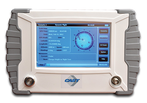
The new SGX GPS satellite signal simulator from CAST Navigation provides the user with dynamic, repeatable GPS RF signals for use in the laboratory or in the field for a wide range of GPS applications. The SGX simulator is housed in a portable, lightweight, handheld enclosure measuring 7 x 11 x 3 inches and weighing just over 4 pounds.
The SGX replaces the CAST-SIMCOM simulator, a 17- inch, 50-pound simulator. The SGX is lightweight and portable, operates on AC or battery power, and features 16 channels of L1 C/A and P codes. Based on CAST’s technology that has been developed for use in the company’s larger military products, it is extremely accurate and repeatable.
The SGX is controlled via an intuitive touchscreen interface that allows the user to select, start, and stop scenarios, change screen views, and change satellite RF power levels while a scenario is running. Three test scenarios are delivered with the simulator.
XGEN Plus Scenario Generation Software. This optional software gives the user the ability to generate custom scenarios for use with the SGX. The software allows for complete control over GPS almanac, ephemeris, and all satellite error sources.
The user can select from a variety of vehicle types and simulate static or dynamic motion. The user may also employ antenna gain patterns and vehicle silhouettes if desired. The user may generate a trajectory by defining a total mission profile using a six-degree-of-freedom model. The new scenarios can be downloaded via USB port or SD card interfaces.
CAST has been in the GPS simulation and support business for more than 30 years, designing, developing, manufacturing, and integrating innovative GPS/INS simulators and associated equipment for government, military, prime vendor, and consumer markets.
www.castnav.com phone: 978 858-0130
email: [email protected]
IFEN Inc.
NavX-NCS Professional GNSS Simulator
NavX-NCS Essential GNSS Simulator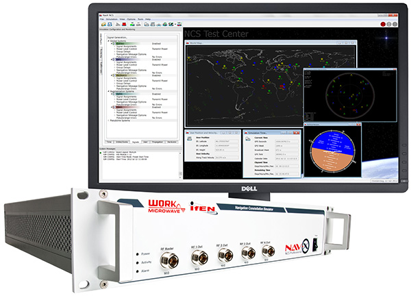
The absolute flexibility of the NavX-NCS Professional GNSS Simulator allows it to be configured with up to 108 channels and all of the following signals:
• GPS L1/L2/L5 C/A & P code and L2C
• GLONASS G1/G2 standard & high accuracy codes
• Galileo E1/E5/E6 (BOC/CBOC/AltBOC)
• BeiDou B1/B2
• SBAS L1/L5 (WAAS, EGNOS, MSAS, GAGAN)
• QZSS L1 & L1-SAIF
• IMESThe user is enabled to assign signals freely to any of the RF modules fitted to the simulator. This allows the same hardware to be used in a range of different configurations.
Signals may be added by software license with no need to return the hardware for upgrade.
Up to four independent RF outputs may be fitted, enabling the user to simulate multiple antenna locations simultaneously (allowing simulation of multiple antennas on one vehicle, multiple vehicles simultaneously, a mixture of static locations and mobile vehicles, and multiple antenna elements forControlled Reception Pattern Antenna [CRPA] testing).
The comprehensive and easy-to-use Control Center operating software allows the operator to quickly create realistic test scenarios for effective testing of user equipment.
IFEN also offers the NavX-NCS Essential GNSS Simulator, which is available with 21 or 42 channels and is capable of simulating GPS L1 (including SBAS L1), GLONASS G1, Galileo E1, BeiDou B1, QZSS L1, and IMES. The simulator is also supplied with Control Center operating software for comprehensive scenario generation.
www.ifen.com For USA and Canada
Mark Wilson
phone: 951-739-7331
email: [email protected] For Rest of World
Dr. Guenter Heinrichs
phone: +49-8121-2238-20
email: [email protected]
RaceLogic
LabSat 3
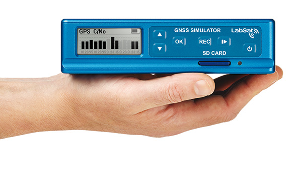
LabSat 3, the latest generation of GNSS simulators from Racelogic, is a low cost, stand-alone, battery powered, multi-constellation, RF record and replay device designed to assist GNSS engineers in the development and testing of their products. With its small size and all-in-one design, LabSat 3 makes it easier than ever to collect raw satellite data in the same environment that end users experience in everyday use. This enables repeatable and realistic testing to be carried out under controlled conditions.
LabSat 3 doesn’t need to be connected to a PC to record live-sky GNSS signals. With one-touch recording to SD card and a two-hour battery life, it can be used in any outdoor location to create real-world scenarios, for eventual replay back in the lab. As well as recording GPS, GLONASS, BeiDou, QZSS, Galileo, and SBAS signals, it can simultaneously log CAN bus, serial, or digital data, embedded alongside the satellite information. This additional information can then be replayed alongside the GNSS output, with synchronization to within 60 ns. A 1 PPS signal can also be generated using the internal GPS receiver.
LabSat 3 can be used as a replay system out of the box with a set of pre-recorded scenarios supplied as part of the package, recorded from various locations around the globe. SatGen software, a free version of which is included with LabSat 3, allows for scenario generation of user-defined trajectories, with precise control over velocity, heading, height, and constellation profiles. Routes are also easily created in Google Maps, and the software also supports NMEA and KML file import. SatGen gives the test engineer the ability to develop a product using simulations that would be difficult or impossible to record due to geographic location or safety constraints.
LabSat 3 is available in four variants: replay only, or record and replay, of a single channel — one of GPS/Galileo/SBAS/QZSS, GLONASS, or BeiDou; and replay only, or record and replay, of dual channels — two of GPS/Galileo/SBAS/QZSS, GLONASS, or BeiDou.
LabSat is currently used by many leading manufacturers of GPS chipsets, portable navigation devices, smartphones, and by major car companies in their test, development, and production processes.
www.labsat.co.uk; phone: +44 (0)1280 823803
Rohde & Schwarz
R&S SMBV100A: GNSS Simulator on Vector Signal Generator
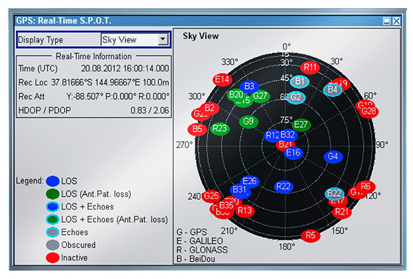
Rohde & Schwarz extends the functionality of the R&S SMBV100A vector signal generator by adding BeiDou/Compass capability to its integrated GNSS simulator. With the R&S SMBV-K107 option, the GNSS simulator now covers the BeiDou standard as well as the GPS, Galileo and GLONASS satellite navigation systems.
The new option allows users to generate real-time scenarios with up to 24 BeiDou satellites. R&S SMBV-K107 supports all possible BeiDou orbits and can therefore even simulate satellites that are not yet in orbit. It also supports hybrid scenarios with GPS, Galileo, or GLONASS satellites. A software update makes it easy to upgrade existing GNSS simulators for BeiDou. No hardware modifications are required.
The R&S SMBV100A permits users to quickly define their own satellite scenarios to test GNSS receivers under diverse conditions. A wide range of options are available for simulating realistic effects such as signal obscuration and multipath propagation. These scenarios can now be configured for BeiDou as well.
This inexpensive solution is one of the few on the market that does not require an external PC for testing receivers and components of satellite-based navigations systems. In addition to GNSS signals, the R&S SMBV100A can simulate mobile radio, wireless, and radio standards, allowing users to test several functions with a single instrument.
The new R&S SMBV-K107 option is now available from Rohde & Schwarz.
www.rohde-schwarz.com email: [email protected]
Spectracom
Configurable, Upgradeable GNSS Simulators
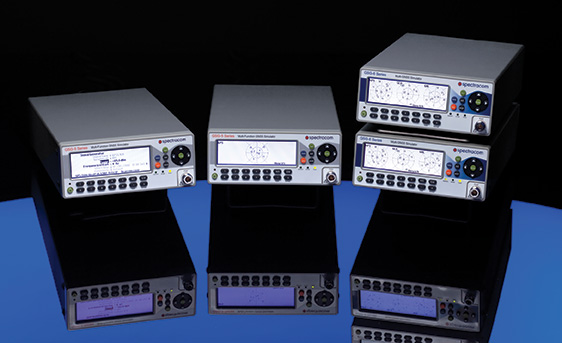
Spectracom multi-channel, multi-frequency GSG Series GPS/GNSS Signal Simulators are designed for research, development and manufacturing. They provide powerful, affordable, and easy-to-use application-specific GNSS testing solutions allowing users to simulate virtually any condition through built-in and user-defined scenarios. The simulators now feature expanded capabilities and a flexible, field upgradeable design that allows users to select only the features needed for a specific application, upgrade when necessary.
The GSG 5 and 6 Series simulators are portable and fully operational via front panel, web-based remote control (Ethernet, USB, GPIB), or SCPI protocol. The models include GSG StudioView PC Software to build, edit, and manage complex scenarios and trajectories. Advanced simulation features include: SBAS (WAAS, EGNOS, GAGAN, MSAS), multipath scenarios, interference detection and mitigation, white-noise generation, and trajectories. The new features and capabilities can be added to any GSG-5 or GSG-6 purchased since June 2012.
GSG-6 Series Multi-Frequency, Advanced GNSS Simulator
• Up to 64 channels and 4-frequencies simultaneously
• GPS, GLONASS, Galileo, BeiDou
• Sync multiple units for testing hundreds of signals
• L1, L2, L2C, L5, E1, E5, B1; [E6, B2, B3 capable HW, with FW upgrade available in the future]
• P-code, pseudo P(Y) in L1 and L2
• Add-ons for real-time scenarios, record and playback, Assisted-GNSS, RTK/Differential measurements, high velocity
• Fully upgradable to future constellations and signalsGSG-5 Series Multi-Channel, Advanced GNSS Simulator
• 4, 8 or 16 channels
• GPS, GLONASS, Galileo, BeiDou
• L1, E1, B1
• Upgradeable to more channels and frequenciesGSG-51 Low Cost Single Channel GPS Signal Generator
www.spectracom.com email: [email protected]; phone: 585-321-5800
• 1-channel GNSS tester for fast, simple manufacturing test and validation
• Fully upgradeable to GSG-5 and 6 series
Spirent Federal Systems
GNSS Simulators
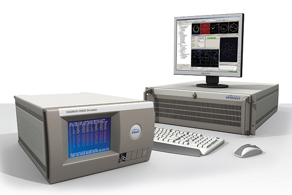
Spirent provides simulators that cover all applications, including research and development, integration/verification, and production testing.
GSS8000 (pictured). Spirent’s flagship simulator, the GSS8000, is fully approved for Y-code, SAASM, AES M-code and SDS M-code testing. Spirent provides options and configurations for testing GNSS interference effects and interference mitigation techniques, such as integrated GPS/inertial testing, CRPA testing, and jamming/anti-jam simulation.
Spirent has delivered simulators that produce legacy signals as well as modernized signals such as 2C, L5, and L1C. In addition to GPS, systems can include GLONASS L1/L2, Galileo, and Beidou-2, plus SBAS (WAAS, MSAS, and EGNOS) and Japan’s Quasi-Zenith Satellite System (QZSS).
CRPA Test System. Spirent’s Controlled Reception Pattern Antenna (CRPA) Test System generates both GPS L1/L2 and interference signals; multiple GSS8000 chassis may be combined to coherently control up to seven antenna elements. Null-steering and space/time adaptive CRPA testing are both supported by this comprehensive approach.
GSS7790. Spirent’s GSS7790 Multi-Output Simulation System allows the signal from each satellite to be mapped to a separate RF output. These signals can then be fed to individual transmit antennas, which, when suitably deployed in an anechoic chamber, replicate the spatial diversity of satellite and jammer signals incident on the receiver antenna. Additional flexibility is offered as the signal is further split into its GPS L1 and L2 components, as appropriate.
www.spirentfederal.com Jeff Martin, Director of Sales
Kalani Needham, Sales Manager
email: [email protected]
phone: 801-785-1448; fax: 801-785-1294 -
The Business — March 2014
The Business section of the May 2014 issue. Download the PDF.
Includes: Spirent’s SimSAFE Fights Signal Vulnerability; JAVAD TR-3 Receiver; Teleorbit Upgrades Simulation Environment; IFEN Contract for Galileo Signal Test Bed; Spectracom Program for Application-Specific Testing; Spectra Precision SP-80 Uses Six GNSS Systems; Briefs
-
Spirent’s SimSAFE Fights Signal Vulnerability
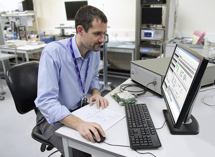
Spirent’s SimSAFE Fights Signal Vulnerability. By Tracy Cozzens
Spirent Communications now offers SimSAFE, a software solution that simulates legitimate GNSS constellations along with spoofed or hoax signals to evaluate receiver resilience and help develop counter measures.
Hoax or spoofing attacks work by mimicking genuine GNSS signals, which mislead GNSS receivers. The military and critical infrastructure — such as wireless networks, banking, and utilities — are especially interested in being able to detect and reject spoofing attacks.
“GNSS signal vulnerability is becoming a significant issue,” said John Pottle, marketing director of Spirent’s Positioning Division. “The industry is beginning to talk more about vulnerability and how we actually think about categorizing the threat — what approaches are there to evaluate performance in the presence of interference signals? If you’re a developer, what approaches are there to clean up your performance? You’ll see us at Spirent being quite a bit more vocal about these areas in the coming months.”
SimSAFE was developed in conjunction with Qascom, a small organization of half a dozen GNSS signal security and authentication experts headed by Oscar Pozzobon, who served as the chief solutions architect for SimSAFE. Pozzobon contributed his knowledge of GNSS security and vulnerabilities, which were then integrated into the SimSAFE system.
SimSAFE provides a means of emulating a spoofing attack, and then monitoring a receiver under attack to evaluate mitigation strategies and countermeasures.
“SimSAFE really gets into details on how a receiver reacts in the presence of the hoax signals,” Pottle said. “By really understanding that, really getting into how is the receiver is acting and reacting, you can understand better how your receiver is likely to behave, and tune it up.”
The SimSAFE laboratory-based test solution is fully controllable, so that users can evaluate a receiver’s response to a wide range of spoofing attacks. As Pottle put it, when fed both authentic and spoofed signals, “What’s the receiver going to see? It’s going to see the authentic signals, it’s going to see a couple of spoofed signals. And you can play around with the spoofed signals — that’s the controllable bit. While this is happening, the detector module within SimSAFE monitors and reports the receiver’s response to the attacks. At its most simple, that’s the power of SimSAFE.”
SimSAFE is aimed not only at receiver developers, a core audience of Spirent’s, but at anyone trying to build a system that may be subject to intentional interference, such as in the military or critical infrastructure. “Those people are starting to ask questions about what should I be worried about? What kind of an attack might I be open to? How can I be sure, if I’ve got a choice of three or four receivers, that I’m going to choose one that meets my needs in terms of resilience to intentional interference?” Pottle said. “Our belief is that SimSAFE will allow people to evaluate different receivers and strategies for mitigating spoofing attacks, and therefore help them to build the right level of resilience in their systems.”
SimSAFE is available in two variants. SimSAFE Simulated uses the simulator for all signals, both satellite and spoofed, using one or more channels for the spoofed signal.
Instead of a simulator, SimSAFE Live pulls authentic signals from sky with an antenna, so the user has the full power of the simulator to generate a much broader range of spoofing attacks. “The clever bit is aligning the spoofed signal with the real signal, getting the timing and frequency synced up,” Pottle said.
Spirent is also working on other technologies to mitigate spoofing, including work with interference signals from ground-based transmitters, adaptive antenna lab-based tests, and integration with inertial sensors, such as in military jets.
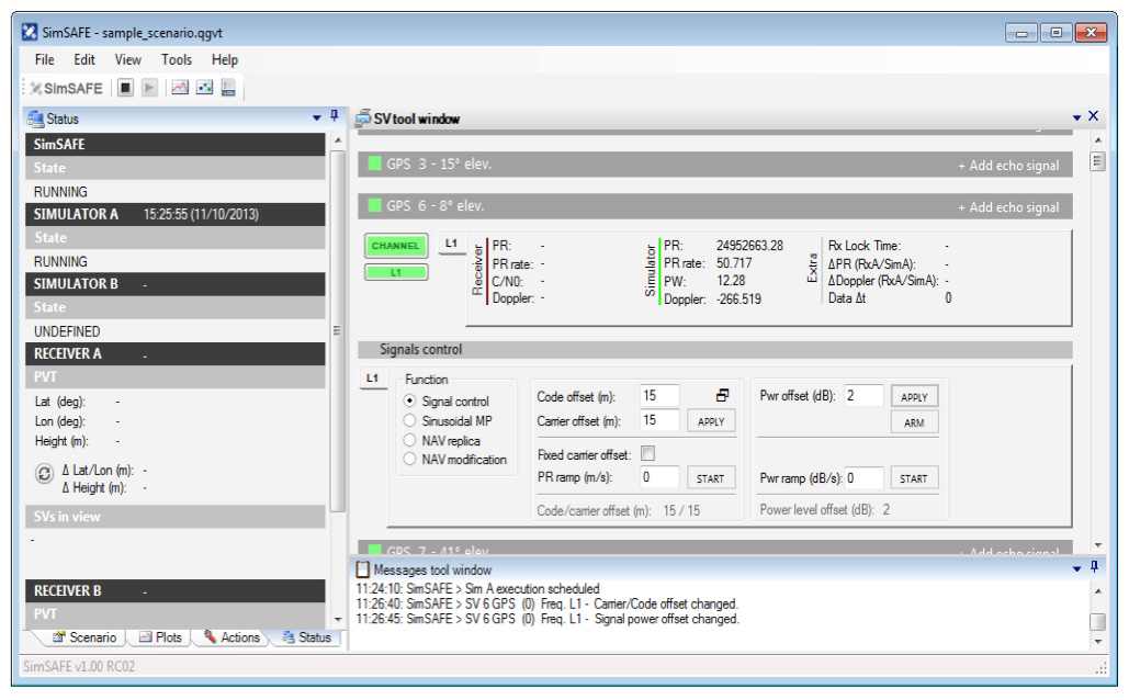
SimSAFE’s signal control capabilities. -
The System: Galileo Accomplishes In-Orbit Validation
Galileo Accomplishes In-Orbit Validation
Nucleus of Four Now Operational: It “Works, and Works Well”
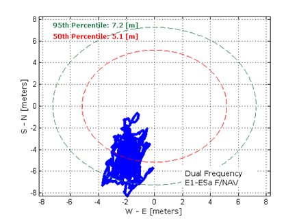
Dual-frequency Galileo positioning performance during the In-Orbit Validation phase: positioning accuracy is an average 8 m horizontal and 9 m vertical (95% of the time). Its average timing accuracy is 10 nanoseconds on average. Plot courtesy of ESA. The European Space Agency (ESA) announced fulfillment of the in-orbit validation (IOV) of Galileo on February 10. IOV was achieved with four satellites, the minimum number needed to perform navigation fixes.
“IOV was required to demonstrate that the future performance that we want to meet when the system is deployed is effectively reachable,” said Sylvain Loddo, ESA’s Galileo Ground Segment manager. “It was an intermediate step with a reduced part of the system to effectively give evidence that we are on track.”
Following a March 2013 first determination of a ground location, jointly by Galileo’s space and ground segments, program managers undertook a wide variety of tests all across Europe.
“More than 10,000 kilometers were driven by test vehicles in the process of picking up signals, along with pedestrian and fixed receiver testing. Many terabytes of IOV data were gathered in all,” said Marco Falcone, ESA’s Galileo System manager.
According to ESA’s elaboration on the test results, the system has proved itself capable of solely performing positioning fixes across the planet.
Galileo’s observed dual-frequency positioning accuracy is an average of 8 meters horizontal and 9 meters vertical, 95 percent of the time. Its average timing accuracy is 10 billionths of a second. Its performance is expected to improve as more satellites are launched and ground stations come on line.
For Galileo’s search-and-rescue function — operating as part of the existing international Cospas–Sarsat programme — 77 percent of simulated distress locations can be pinpointed within 2 kilometers, and 95 percent within 5 kilometers. All alerts are detected and forwarded to the Mission Control Centre within a minute and a half, compared to a design requirement of 10 minutes.
“Europe has proven with IOV that in terms of performance we are at a par with the best international systems of navigation in the world,” said Didier Faivre, ESA director of Galileo and Navigation-related Activities.
Historically Speaking. In a February 2013 GPS World article, Peter Steigenberger, Urs Hugentobler, and Oliver Montenbruck discussed Galileo-only positioning. “Using an ionosphere-free dual-frequency linear combination of pseudorange measurements on the Galileo E1 and E5a frequencies, the position of the TUME reference station [at the Technische Universität München (TUM) in Munich, Germany] could be determined with a 3D position error of less than 1.5 meters,’” the authors said.
Crystal Ball Gazing. The next two Galileo satellites, of the full operational capability (FOC) class, currently complete their testing for flight clearance at ESA’s ESTEC facility.
Six such satellites are destined to rise into space in 2014, according to ESA’s master plan. Should all those launches occur as scheduled, Galileo’s initial services could start by the end of the year.
GNSS Vulnerable: What to Do?
Too Much Sensitivity, Not Enough Robustness, Says Parkinson
Brad Parkinson, the founding architect of GPS, told a UK conference that the system needs to be made more robust to ensure worldwide availability of services to users. His concerns over GPS availability relate to threats such as the loss of authorized frequency spectrum (implicitly creating licensed jammers), space weather due to hyperactive ionospheric conditions, and deliberate or inadvertent jamming of GPS signals.
He warned that GPS is more vulnerable to sabotage or disruption than ever before, and charged that politicians and security chiefs are ignoring the risk. Western governments are “in their infancy in recognizing the problem,” he remarked further in an interview with London’s Financial Times. “[In the United States] I don’t know anyone that is really in charge of it. The Department of Homeland Security should be [but] … they don’t have any people that understand it very well. They’ve got one person without any budget to speak of.”
He also warned that Europe’s €5 billion Galileo system is equally at risk.
Parkinson proposed a three-stage program to:
- Protect (legally) the signal and physically eliminate jamming sources;
- Toughen the GPS/Galileo receiver’s resistance to interference;
- Augment the GPS signals with other satellites or with ground-based transmitters such as eLoran.
To support his proposal, Parkinson stated, “The number one need for all GPS or Galileo users is availability. Over the years, manufacturers of signal receiver technologies have focused too much on sensitivity and not enough on resilience or robustness. The maritime industry is a particular concern where users have taken GPS for granted. They must increase preparedness and backups as they do in aviation or other GNSS-using industries.
“Even today, most ships have only GPS and the vision of their crew to guide them when approaching harbors. As you can see from today’s conference, there are a wealth of solutions to toughen and back up GPS, many of which are not technologically difficult nor expensive, but still their adoption in sectors such as global shipping is certainly not adequate.”
As part of his protection program, Parkinson urged that penalties for jamming GPS networks be coordinated worldwide. “In Australia, if you cause interference likely to cause prejudice to the safe conduct of a vessel, it’s five years in the jug [jail] and $850,000.” Contrasting this with a U.S. case that may simply impose a forfeiture of the culprit’s jamming device, Parkinson added, “I’m calling for the community of nations to move to the Aussie-type penalties.”
In the toughening regard, Parkinson alluded to integration of GPS data with information derived from an inertial positioning system. “If you combine all of these things, a good set should be able to fly within 1 kilometer of a jammer with a 10-kilometer range,” said Parkinson. “That’s what I call toughening.”
Parkinson made his remarks as the keynote speech at GNSS Vulnerabilities and Resilient PNT 2014, hosted by the Royal Institute of Navigation. He will also deliver the keynote address, “Assured PNT: Assured World Economic Benefits,” for the European Navigation Conference on April 15 in The Netherlands.
GLONASS Seeks Broader Monitoring Footprint; Launch Imminent
Russia will deploy as many as seven ground monitoring and augmentation stations for GLONASS outside its national boundaries. GLONASS/GNSS Forum Association Executive Director Vladimir Klimov stated that “It is planned to deploy about six or seven stations on foreign territories this year.” Negotiations for the stations are now taking place with foreign nations.
Currently, there are 46 GLONASS ground stations on Russian territory, eight in neighboring countries, three in Antarctica, and one in Brazil. The United States recently spurned, with some Congressional trumpeting, a Russian tender to site one of the ground stations on U.S. soil.
New Instrument in Space. In mid-February, the most recent GLONASS-M satellite traveled to the Plesetsk cosmodrome for a probable mid-March launch. GLONASS-M 54 will carry a high-accuracy thermal stabilization unit, installed on the spacecraft for testing and flight qualification. The next-generation K-class of GLONASS spacecraft will loft this device to provide increased positioning accuracy.
Five GLONASS-M craft are planned for launch in 2014, in one triple and two single launches.
-
Recording and Replay for Multiple Constellations and Frequency Bands
The design and verification of a new class of portable wideband record-and-playback system considers the relative merits and limitations of both simulator and record/replay approaches. The authors also discuss the benefits of the different test approaches to the development and characterization of various GNSS receiver types.
By Steve Hickling and Tony Haddrell
As new GNSS systems become available, and users take receivers to ever more challenging environments, the need for repetitive and repeatable testing during development grows ever stronger. Simulators have traditionally demonstrated performance and repeatability in the laboratory environment, and this approach remains the only option for planned signals not yet broadcast from space. However, this approach is becoming more complex as the number of GNSS signals and their reception environments increase.
Another way of testing receivers is through field trials. This allows investigation of conditions difficult to simulate, such as multiple reflections and interferers. These environments, however, are time-varying, and thus not repeatable in the true sense. Therefore, proper comparisons can only be made by assessing all competing receivers in the same trial, and any performance anomalies seen cannot necessarily be tracked down by returning to the same location at some point in the future. Furthermore, developers would like to see for themselves any such anomalies and try to understand and correct them, but it is not always desirable or practical (and certainly not economical) to put development engineers in locations scattered all over the globe.
To tackle this problem, GNSS signal record-and-replay capability is gaining acceptance as a practical tool for recording a signal environment at a single point in time and replaying at will. In real terms this means a device must receive the radio signals from the GNSS satellites, reduce them to a form suitable for storage, and then recreate signals from the stored data in a manner that makes them look completely real to any receiver under test or development.
Some receiver manufacturers developed their own capability to do this. Early devices were of necessity restricted in the signals they could handle and store, limited both by budget and available technologies. The basic problems are the amount of data to be stored in real time and the ability to recover it in real time. Even the GPS L1-only low bandwidth C/A code requires at least 2 Mbytes per single second of recording, or more than 100 Mbytes per minute.
Fortunately, with digital storage technology advances, we can now make use of higher storage capacities (1 TByte of storage is readily available at reasonable cost) and also higher write/read bandwidths (100 MBytes per second is realistic). All we need is some hardware and a processor that can handle the data rates.
Once we have our wanted signals reduced to some form of digital representation, we can simply store and retrieve them at will, handling the recordings as simple, if somewhat large, data files. This allows file distribution between equipments, and a split between making the recording in the field and replaying it in the laboratory. In fact, many manufacturers have dedicated field recording teams who send the files back to the engineers interested in the signal environments.
Replaying the signals is in some ways similar to generating simulated signals. In both cases, the starting point is digital data, on the one hand recorded in the field, on the other hand calculated by mathematical algorithms using the scenario specified in the simulator. In both cases the signal is created by generating radio frequency (RF) carriers and modulating them according to the GNSS signal formats.
Contrast of Two Approaches. None of the characteristics of the record/replay device replace the functionality of the simulator; in fact, both are valid tools for development and testing. For instance, it is not possible with a record/replay device to manipulate individual satellite signals, nor to introduce specific errors in the radio signals. Equally, it is not really possible with a simulator to recreate a particular physical environment made up of many reflected signals, jammers, manmade noise, and moving scenery. With a simulator, the user has control over the power of the received satellite signal, whereas in the recorder the entire signal-to-noise ratio observed at the point of reception has been recorded, and the user can only control the amplitude of the entire noise plus signal.
Permanent Signal Monitoring
One other aspect of raw signal recording lies outside the receiver testing topic, but is of interest for GNSS signal monitoring. It uses the ability to record GNSS signals all of the time, in this case from a good signal environment, and then to retain any time spans where an anomaly in the signals has been detected by a monitor receiver. This is comparable to recording security CCTV pictures, where we expect nearly all of the resulting files to be redundant, but can retain the interesting bits to replay over and over for further analysis. For example, if it is known that a given timing receiver installation suffers periodic loss of lock, it is possible to make a recording using the loss of lock to signpost the interesting region in much the same way as a reverse trigger on an oscilloscope.
Limitations and Compromises
The sheer function of recording GNSS signals off-air has some built-in limitations. First, the signal recorded represents only a snapshot of the environment, although numerous recordings can be made at, say, busy and quiet times, day and night, etc. This is really a reversal of the “non repeatability” aspect of measuring performance in a particular location. In the recording sense, we only get repeatability, with no guarantee that the scenario captured represents worst case conditions. Thus, going back to the location in the future may or may not provide similar results.
In addition to this, there are some signal processing aspects that limit the fidelity of the replayed signals. The first is that any recorder must have an external GNSS antenna and a GNSS receiver front-end built in, and this combination will receive both the satellite signals and thermal noise. The level of the noise is much higher than that of the signals if we don’t do any correlation related processing, and the receiver will contribute some more noise of its own (the noise figure of the system). The second aspect is that in downconverting the radio signals to a usable frequency for sampling and storage, the recorder must use some frequency reference of its own, which will contribute some frequency uncertainty and some phase noise (or jitter on the frequency). The final aspect is the digitization of the downconverted signal to get it into a suitable form for manipulation and storage. Since we are essentially sampling noise here (with the GNSS signal buried in it) we need to look at fidelity in reproduction of the noise during playback, and the effect of any signal (a jammer or interferer) that is above the amplitude of the noise. In analyzing this last aspect, we may include the effect of any automatic gain control (AGC) used to present the correct amplitude signal to the analog to digital (A2D) converter.
A New Simulation Requirement
We wanted to create a much more comprehensive and flexible device than hitherto available, going part way towards the much more general (and expensive) instrumentation recorders that are currently the only alternative.
The requirement is for a flexible, self-contained device that can be easily carried or transported for recording purposes, so having an internal battery and built-in control functionality, and simultaneously a device that fits neatly into a networked and externally controlled laboratory environment.
The first approach was to cover all of the possible GNSS frequency bands, although as more are added with time, we realized that this needed to be moderated somewhat. So the product covers L1, L2, L5 and their derivatives for the differing GNSS systems GPS, GLONASS, Galileo, and BeiDou, and also the Inmarsat commercial band to cover the proprietary augmentation signals used by many high-accuracy receivers (see Figure 1, red outlines).
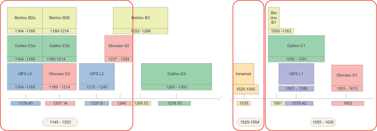
FIGURE 1. Frequency bands, outlined in red, supported by the new record-and-replay device. The next decision was what bandwidths to allow at each frequency, and how much of this bandwidth could be covered at once. The limitations here are driven by the data storage requirements of the signals being recorded, and the speed that they can be written to disk. The resulting solution allows bandwidths (BW) of up to 30 MHz at each frequency, and any three such bandwidths to be recorded at once. Physically, this is implemented with three channels with the ability to record any of the available frequencies or bandwidths. The user has, therefore, flexibility to set up recording for his particular needs, which may be just L1 covering BeiDou, GPS, Galileo, and GLONASS, or an L1,L2,L5, combination for a survey type application.
Of course, there are always requests for more capability, and we envisaged early on the ability to stack two devices to give six channels of 30-MHz BW for recording, say, GPS/Galileo and GLONASS at L1, GPS and GLONASS at L2, Galileo/GPS at L5, and an Inmarsat data carrier. See later for how this is achieved.
The whole product has to fit in a portable box with enough battery power for more than one-hour field campaigns, and also be capable of running from mains or vehicle power. The associated antenna needs to cover all of the frequency bands. Figure 2 shows the end result in its standalone configuration.
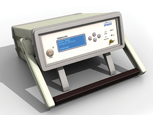
Figure 2. Portable solution for recording. One additional requirement was placed upon the design, and that is the ability to record and replay non-GNSS data simultaneously with the GNSS signals, and reproduce them, if desired, in synchronism with the replayed signals. This allows time ticks, events, assistance data, sensor data, or even video to be stored and replayed along with the raw signals.
Architecture and Implementation
The new record-and-replay device uses a fast computer running the Linux operating system as its control center and storage/retrieval engine. Dedicated hardware is used to format or recover the raw data, and this has access directly to the computer bus to minimize the delays in writing or reading the mass storage, which in this case is a solid state hard drive (SSD). The overall architecture is shown in Figure 3.
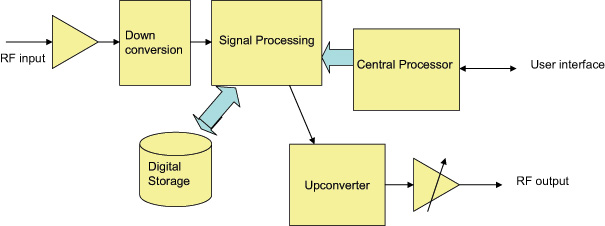
Figure 3. Concept-level architecture. The signal recording capability hinges around the RF planning, which has the task of supplying the necessary flexibility without adding more than minimal signal degradation.
For the RF functionality, the device contains a broadband front end and a three-channel RF amplifier (L1, Imarsat, and L2/L5), filtering the signal down to reasonable bandwidths for later downconversion. Three independent channels of downconversion to baseband I and Q analog signals have access to any of the RF channels and are based upon satellite TV technology architectures. The downconverters have baseband filters that can be commanded to a desired bandwidth by the control processor. This allows the use of narrower bandwidths where possible, allowing more recording time for a lower sampling rate. The baseband signals are sampled at 10 MHz or 30 MHz, paying attention to the Nyquist requirements for pre-digitisation filtering. Two bits for each of the I and Q signals are utilized for packing into the recorded file format. Figure 4 shows the arrangement.
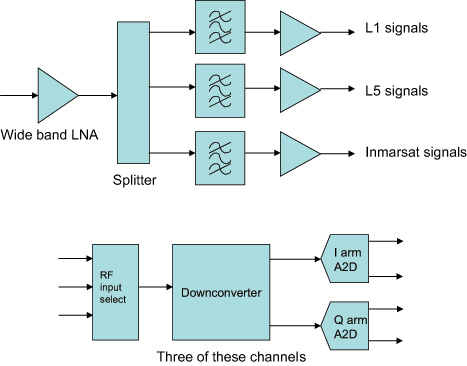
Figure 4 . The RF architecture. At this stage any additional synchronous data to be recorded, such as truth or assitance data, is inserted into the bit stream, and the data from all the channels in use is combined in a pre-determined format. Dedicated hardware is used for this, and large data buffers are provided to alleviate bottlenecks in sending data to the disks. Each file has an associated definition in a header, and contains synchronization data to allow the device to set up the replay path and recover the data bits in order to reproduce whatever combination was recorded. Note that resulting data files are given the same extension, regardless of content. Data files can be very big (at maximum bandwidth we record about 2.7 Gbytes per minute) and may be difficult to handle once recorded. To assist with this, the device has a second, removable SSD on board, allowing recorded files to be simply popped out of the caddy and shared with another device, or even mailed or couriered. The RF path for the replay consists again of three independent channels, able to generate any of the supported frequencies and modulate upon them the original signals recovered from the stored file. Once again, dedicated hardware and large buffers are needed to unpack the files and send the RF data to the correct channels or to the synchronous data outputs in the case of recorded digital data, as determined by the file header.
The data representing the recorded RF is converted back to analog form and filtered before being applied to modulators which regenerate the original channelized signals. Each channel has a programmable attenuator to “level” the amplitude, and the three channels are then combined together before passing through a common attenuator to provide user control over the replayed carrier to noise ratio (C/N0). Figure 5 shows the upconverter arrangement.
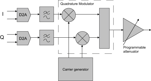
Figure 5. An upconverter channel. All frequencies created within the device need to be traceable to a common reference. In addition, this reference needs to be at least as good as the reference in any receiver to be tested, since both its offset from true frequency and its rates of change will be superimposed on the replayed data. Many commercial-grade GNSS receivers (such as those used in mobile phone) are specifically designed to cope with poor oscillators, for instance a low-grade temperature controlled crystal oscillator (TCXO), whereas more professional receivers may expect a couple of orders of magnitude better performance. We decided, therefore, to include an ovenized oscillator (OCXO) for use both in record and playback modes. One challenge presented by this decision is that the oven is necessarily thirsty for power, and therefore a bigger battery is needed than would otherwise be the case.
The OCXO used is a 10.23-MHz component, thus allowing direct generation of the wanted GNSS frequencies using integer ratios and avoiding as much phase noise as possible in the various RF channels. A dedicated phase locked loop (PLL) generates a reference for output to other devices, and a 10-MHz input connector is provided to lock the OCXO to an external reference. These capabilities are utilized when combining two such devices, since we must have the same frequency reference in each. Apart from locking the two oscillators together, this configuration also needs time synchronization between the sampling in both devices, and this is achieved via an additional cable connected between the accessory connectors. Once time and frequency synchronized, the devices behave as a single six-channel unit, using external RF splitter/combiners for the RF connections.
Design Challenges
RF Total Bandwidth. The GNSS bands covered by the device range from the L5 band to the GLONASS L1 band, a total range of 480 MHz allowing for signal bandwidths. Table 1 shows the relevant bands.
Whilst the RF front end must be wide open to this range, assuming the use of a single RF input port, it is obviously necessary to provide bandwidth narrowing by filtering as soon as possible, to exclude jammers or carriers using the space between the GNSS bands, and to avoid the sheer noise power overwhelming the RF circuits. Examination of the supported GNSS services shows them essentially packed into two clusters of frequencies, which provide a convenient way of filtering down the RF input into two RF “channels.” This gets the total bandwidth down to about 180 MHz. Figure 1, the opening graphic for this article, shows the groupings. Beidou B3 and Galileo E6 are currently out of scope for this product, but will be supported in a later version.
The Inmarsat-supported signals are assigned their own RF path, since their structure is data modulated carriers, usually with low SNR. Elsewhere in the Inmarsat band there are more powerful carriers supporting comms traffic, which can “grab” the AGC and therefore cause loss of SNR during the digitization process. Hence this band is processed though its own RF path, maintaining as low a bandwidth as possible consistent with the frequency allocations of the various (proprietary) GNSS augmentation data carriers.
Tradeoffs. Throughput of the recording or replay paths is the performance limitation of the current architecture. Thus a lot of discussions and simulations concerning possible bandwidth, sampling rates, and bit depth tradeoffs was undertaken at the outset of the design. In addition, we needed to decide whether to sample signals at an IF frequency or at baseband. Trials were conducted to determine the real rates of disk access, which are different to the often quoted write and read speeds of computer interfaces.
The results of the trials and simulation led us to adopt a maximum average data rate to/from the storage system of 50 Mbytes/second, this being shown to be available over a period of many hours. Actually, at this rate we fill up a 1-Tbyte disk in about five hours.
To service the GNSS signal bandwidths of interest, again there are two groups of signals. This time we are looking at either the commercial signals (“open service signals” in some systems’ parlance) used by consumer-type receivers, which are relatively narrow band, and the military, high-accuracy, or resilient signals of interest to surveying and precision applications. Therefore, we offer two sampling rates, approximately 10 and 30 MHz, to avoid building large files where more than half of the bandwidth was of no interest to the user.
Next, we have to look at bit resolution. Given that we have generally a noise-like signal with Gaussian characteristics, if we were looking at digitizing at an intermediate frequency (IF), it can be shown that a 2-bit analog-to-digital converter (A2D) would be sufficient to keep the digitization losses to less than 1dB. Obviously, the fewer number of bits we need to store the better, commensurate with achieving the performance targets.
Frequency planning for all of the possible frequencies and bandwidths of interest is a complex task. The requirement here was to downconvert each signal of interest to a low IF suitable for digitizing, whilst having control of the bandwidth to eliminate unwanted signals and fulfill the Nyquist criterion. In addition, we wanted each channel to be isolated from the others even when the replay path involving the generation of the IF carriers was considered.
We therefore decided to downconvert to baseband for each channel, to avoid cross-contamination via the various IFs that would have to be generated for replay. In other words, we adopted an IF of zero Hz. This in turn means that the final bandwidth-determining filters are at baseband, and can readily be controlled by software means rather than having to switch RF paths. By downconverting into quadrature baseband channels, all stored signals are at the same (zero) IF, and crosstalk and imaging during upconversion is avoided.
Thus the A2D architecture of 2 bits in the inphase (I) and 2 bits in the quadrature (Q) arms of the downconverted signal was adopted. Doing the calculation in terms of stored data, we see that we can operate three channels inside our target storage bandwidth, with a margin left for other features such as storing video at the same time.
- For 30M samples per second (SPS), each channel has 4 bits or 0.5 bytes
- Therefore, for three channels the storage bandwidth is 0.5 * 3 * 30 MSPS, or 45 Mbytes/s
To keep the optimum A2D characteristics, the AGC is designed to adjust the signal amplitude at the converter to give a Gaussian response to the four states determined by the two bits in each arm. The AGC operates independently in each channel. Figure 6 shows the final architecture for the device in block diagram form.
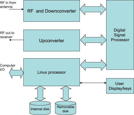
Figure 6. Final architecture. Real-Time Data Handling. Storage and retrieval of the digitized signals is carried out by dedicated hardware connected to the RF downconverter, the playback upconverter, and the main computer that “owns” the storage media. Large buffers allow the storage media to lag (record) and lead (playback) the real-time signals in time, and to take short breaks for housekeeping functions. Data is packed into a binary file according to a pre-determined sequence, which in turn is set by the number of channels and bandwidths in use. A file header is generated which contains all of the information necessary for reconstructing the data streams for replay. A synchronization sequence is added at the start of the file to allow recovery of the correct bits for each channel and each baseband quadrature arm, and to the correct timeslots for each component. Destroying the correct time reproduction is the most likely issue to cause faulty replay in any record/replay device. GNSS receivers don’t like discontinuous or slewing time!
This approach also allows the insertion of external digital data into the file. Providing the data processing hardware is aware of the individual bits into which this data is placed, digital data recorded at the same time as the raw signals may be regenerated synchronously during replay. Thus any data that is applied to a receiver in a real time trial can be available for the same trial any time after the event. Two streams of synchronous data can be recorded per channel potentially making six serial data streams per chassis available.
User Interfaces
A final challenge presents itself in the case of user interfaces. Although the operational options of the device are quite complex, there is a requirement to be able to capture field data with just the equipment itself and any necessary antenna setup. Consequently, the product has a display and control keys implemented on the front panel, allowing the user comprehensive access to the internal functions using a menu system and scrolling displays. Alternatively, for operation in a lab environment, a network connected user interface is specified, and this requirement is supported by a webserver running on the main processor in the device. Thus, simply opening a web browser and connecting to the device’s IP address allows full functional control.
In addition, connecting a mouse, keyboard, and monitor to the device allows access to the main processor, allowing the running of scripts thus providing full control of replays and receiver functions for running continuous tests in an automated laboratory environment. Using this approach, receiver modifications can be tested over many scenarios and locations many times each, to provide statistically relevant results, without taking up operator time. Remote monitoring is possible using the webserver.
Performance Testing
A range of tests and trials have been carried out to verify that the product meets its specifications, and to measure the performance in a number of real life scenarios.
Repeatability, Degradation, Attenuation. The first and most obvious thing to explore is the effect of the record and playback on signal-to-noise ratio. Since the RF circuits add some noise to the signal recorded, we would expect some degradation to take place here. Also, during replay, the receiver under test adds more noise, depending on its noise figure, although this should be the same as would be added when using “live” signals. Many receivers adjust for their noise figure when reporting C/N0 numbers (C/N0 is a signal to noise measurement normalized to a 1-Hz bandwidth and is the standard reported measurement for most GNSS receivers). However, by replaying back the recorded signal and noise at a higher level than would have been received in “live” conditions, we can eliminate almost all of the degradation. In live versus replayed tests for individual satellites using a JAVAD receiver, which allows us to test all of the supported bands and constellations, we found that replay is possible within ±1 dB of the original live signals. Replayed signals were about 10 dB above the original recorded level to achieve this, effectively swamping the receiver’s noise contribution.
An interesting aspect of controlling the C/N0 this way is the ability to attenuate the replayed signal and, therefore, increase the contribution of the test receiver’s noise figure. Thus, although the recorded C/N0 hasn’t changed, we can attenuate the replay level and use the receiver to add noise.
This process is not linear, and we obviously have to remove nearly all of the 10-dB excess to get started. The device keeps a table of attenuation vs C/N0 reduction, allowing the user to simply dial up the required C/N0 loss. Since this depends on the receiver noise figure, effects may differ slightly from receiver to receiver. Usefully the table is user definable allowing tailoring to a specific receiver.
Losses from Phase Noise, Other Factors. This category of degradation is more difficult to quantify, since the effects are on tracking and therefore range and phase measurement rather than signal to noise ratio. One way of looking at this is, therefore, to establish the positioning performance during live and replayed sessions, and measure the differences. This has some complexity, though, since putting the same signals into a receiver multiple times yields differing performance each time, meaning that we have to use some statistical analysis. Of course this isn’t possible on live signals, and is one reason why repeatable replayed signals are so important in developing GNSS receivers. Another aspect is the fact that some of the effects are differential among frequency bands (filter delays, for instance) and across bands as well (group delay) and also occur in the receiver under test, which will have been calibrated to mitigate its own contribution.
Figure 7 shows a comparison of static positioning for live and replayed signals using only GPS L1 and a 10-MHz sampling rate with an ST-Ericsson receiver, whilst Figure 8 is from a JAVAD receiver using all possible signals in live mode and GPS L1/L2 and GLONASS L1 in replay. In both cases the degradation is within 1 meter always, and much less than this when statistically analyzed.
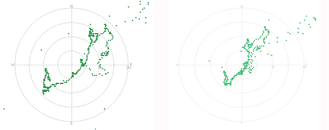
Figure 7. Static position GPS L1 comparison: live left, replayed right. 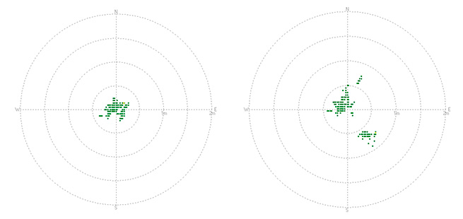
Figure 8. GPS L1/ L2 with GLONASS L1 comparison. Another opportunity to measure the effects is to run a zero baseline phase solution, whereby the receiver is used as the “base station” when receiving live signals which are simultaneously recorded. During replay, the same receiver is used as the “rover” with RTK corrections coming from the previously captured live session. In this setup, therefore, we are really only measuring differences in the replayed and live signals, and the usual measurement limitations of the receiver.
Figure 9 shows the results of one such test, with the pseudorange and carrier phase residuals plotted. This was carried out using two devices in master/slave mode recording GPS L1, L2, L5, and GLONASS L1, L2. As can be seen, the residuals are within “normal” expectations and are measured as 0.42 m RMS for the pseudorange and 1mm RMS for the carrier phase.
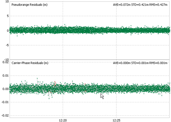
Figure 9. Residuals from zero baseline replay. Drive Test
One of the most common uses for the recorder is to capture the signals at a particular time in a chosen “difficult” environment, A number of representative trials were carried out and we were able to demonstrate consistent results and repeatability. In some cases, the replayed signals yield better performance than live ones, which of course is possible given the differing receiver responses per signal run.
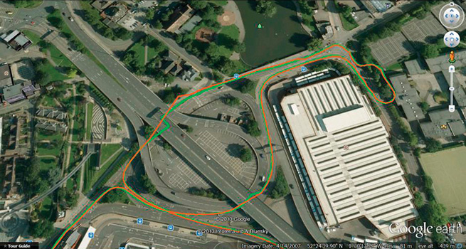
Also, the more times a receivers sees the same time span, the more ephemeris and iono data it can build up, especially true of built up areas where data acquisition is difficult. Figure 10 shows a small section of the City of Coventry in the UK, where the green trace is the “live” plot and the replayed one is in orange. Much of this route is under roads or buildings.
Figure 10. Live and replayed drive around in Coventry. Dynamic Range and Fidelity
When jamming signals are introduced, the dynamic range comes into play. The earlier discussion of the 2-bit I and 2-bit Q architecture is tested here as the performance of the AGC and A2D is critical in maintaining the fidelity of the GNSS signals in a jamming environment. Note that we are not addressing deliberate jamming here, any “controlled” jammers can be added with an RF mixer at replay. Instead, we are concerned with the everyday jamming environment encountered just about everywhere electronic equipment is deployed.
A test was carried out to determine the dynamic range of record/playback paths. A simulator was used as a GPS L1 signals source, and progressively larger jamming signal added via an RF power combiner. The resultant C/N0 in a test receiver was plotted using the live signals which were recorded at the same time. A subsequent replay of those signals was then plotted on top of the original C/N0s. The result is in Figure 11.
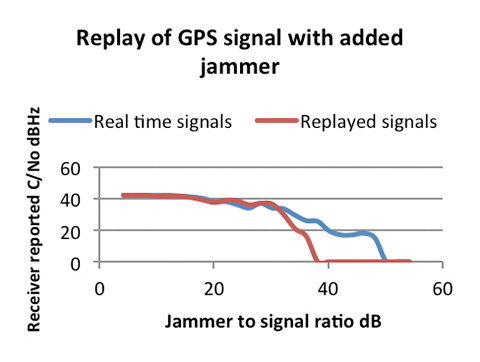
Figure 11. Results of the increasing jammer test. As can be seen, with low jammer powers the real-time and replayed C/N0s track very closely. The ST-Ericsson receiver we used has some signal processing mitigation built in, and so only shows slow degradation as the jammer power is increased. In the real-time run, it was able to track satellites with the J/S ratio greater than 44 dB (and therefore >25 dB above the noise)
On the replayed line, we see the dynamic range limitations start to dominate the replayed signal when the J/S reaches about 30 dB, or 11 dB above the noise, which aligns well with the theoretical analysis of the digitization strategy. This range is sufficient for most environments encountered in real tests.
In Use and Additional Capabilities
With so much flexibility we find that users have a diverse range of applications for the device. These range from multi-constellation usage at L1 only, allowing BeiDou, Galileo, GLONASS, and GPS to be captured, to full six-channel recordings using GPS, GLONASS, and Galileo at L1, L2, and L5 along with an Inmarsat-based assistance channel. For the first time in this class of device, recording of the “military” bandwidth signals is possible. User feedback has been favorable, especially since the unit opens up new capabilities for receiver development and testing.
A small margin of recording bandwidth has been put to use with the ability to record video alongside the raw GNSS signals, and to replay it simultaneously. This allows developers not only to see the performance of their receiver in difficult signal environments, but also to gain a visual idea of the physical environment. Figure 12 shows a receiver control panel along with video pictures of the recorded environment.
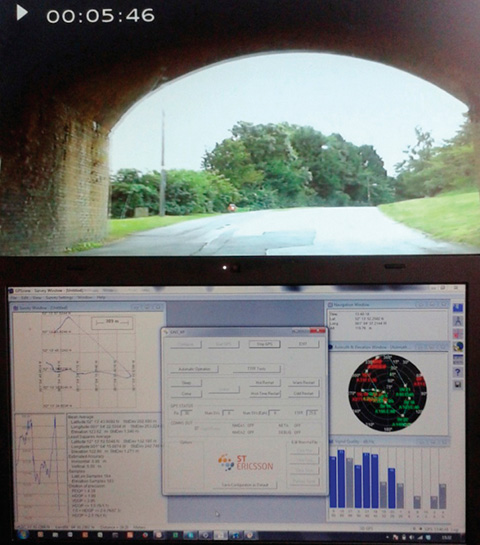
Figure 12. GPS L1 and video synchronized replay Conclusion
Early user feedback has validated the concept behind the device. Although the device will cover additional GNSS constellations and bands as they become operational, for the present the technology is stretched about as far as it can be consistent with the development of a timely and cost effective device. We will continue to address the compromises in the search for more performance, no doubt pushed by user demands.
Acknowledgment
The authors thank their colleagues at Integrated Navigation Systems and Spirent UK for support and access to design and user information.
Manufacturer
This article describes the GSS6425 from Spirent Communication.
Steve Hickling obtained his joint physics and electronics degree from the University of Birmingham. He is responsible for Spirent’s GNSS test solutions as lead product manager in the positioning business.
Tony Haddrell obtained his degree in physics at Imperial College, London, and is technical director at integrated Navigation Systems. He is a consultant to GNSS companies and a visiting lecturer at Nottingham University.