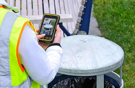
Handheld Group, a manufacturer of rugged mobile computers and smartphones, has launched the Nautiz X4 rugged handheld. The Nautiz X4 is a multipurpose compact handheld computer built for the mobile worker. It enables efficient and reliable data collection in the toughest environments, the company said.
The Nautiz X4 is a compact and lightweight rugged handheld computer that is optimized for efficient field data collection. It has been designed and developed specifically for mobile workers in tough environments in industries such as warehousing, logistics, transportation, utility, field service, security and public safety.
The Nautiz X4 rugged handheld computer has an integrated u-blox GPS receiver that provides professional-grade navigation functionality. It also offers multiple connectivity options, such as high-powered 3G and excellent Wi-Fi capability, the company said. It has a high-speed 1-GHz processor, 512 MB of RAM and 1 GB of flash memory. It runs Windows Embedded Handheld 6.5.
Measuring 156 x 74 x 25.5 millimeters (6.1 x 2.9 x 1.0 inches) and weighing 330 grams (11.6 ounces), the Nautiz X4 is an ergonomic work tool and one of the thinnest and lightest handheld computers in the rugged-device sector, the company said. It features a high-brightness, sunlight-readable resistive touchscreen for reliable computing in challenging worksite environments, and comes with either a high-performance 1D laser scanner or a 2D imager for fast, accurate scanning and barcoding tasks. The device also features a 5-MP camera with auto focus and LED Flash.
The Nautiz X4 has an IP65 Ingress Protection rating, which means that it is impervious to dust and highly resistant to water — the unit can be used in dusty work environments as well as in heavy rain, and can be rinsed off if dirty. It also meets stringent MIL-STD-810G military test standards for overall durability and resistance to humidity, shock, vibration, drops, salt and extreme temperatures.
“Mobile data collection is performed in warehouses as well as outdoors, in all kinds of weather and for long work hours. It may be cold and it may rain or snow. So the field worker needs a computing tool that can not only handle adverse weather conditions, but is also ergonomic and user-friendly,” said Jerker Hellström, CEO of Handheld Group. “For this, we are proud to introduce the Nautiz X4, a new rugged handheld computer that merges ultimate mobility with true field functionality in a handy package and at a very attractive price. We are confident that the Nautiz X4 will be the obvious choice for mobile workers in a wide range of industries.”
At the turn of the century, the premise was that GPS was revolutionary, would work everywhere we needed it, and everything else was old hat. Turns out that we need something that works indoors and in critical outdoor applications without a clear view of the sky, like downtown cores, dense forests, and in-and-out of coverage places like mountain valleys. A Canadian team out of Calgary obtained a couple of key patents and founded a business around navigating with sensors when GPS/GNSS was obscured or just plain not available. Just coincidentally, around the same time, cell-phone and tablet manufacturers were adding these same sensors to their devices so users could readily re-orient screens and play motion video games.
I spend winters in Florida, and in the summer I’m in Calgary, Alberta — of late, “summer” can be a somewhat misunderstood term when talking about weather in that part of Canada; many may recall the devastating floods in that region this year, but nevertheless it’s my home for several months of the year. This year while I was there, I visited Calgary-based Trusted Positioning, Inc., in its offices across from the University of Calgary (UofC), and again at the ION convention in Nashville. I recently had the opportunity to catch up with the staff again and to get a progress update on their unique business and positioning technology.
To bring us all up to scratch on who or what is Trusted Positioning, Inc., (TPI) and where they came from, here’s a brief refresher.
TPI has been around since 2009 as a spin-off of geomatics engineering research by its four founders at UofC. Naser El-Sheimy was the prof, and Chris Goodall (now TPI’s CEO) and Zainab Syed were his grad students when MEMS started to become of interest to the group — their focus had previously been largely on tactical grade IMUs and integration with GPS. They put together a report in 2000 on the opportunity that MEMS offered for navigation, and this started them thinking of potential commercial prospects.
So the following year, two proposals were submitted and ultimately accepted by Canadian government support agencies. This eventually provided start-up funding for what was to become TPI. Chris and Zainab earned their Ph.D.s in 2008, and Jacques Gregory joined them from Queens University in 2009. The first two or three years were tough, and El-Sheimy advises if you are not prepared to give up your existing lifestyle throughout the launch period — family, fun, vacations, finances, even sleep — don’t take on starting such a business. In this case, things ultimately worked out for the founders, and TPI is now launched and doing well.
In those days, the premise was that GPS was still revolutionary, would work everywhere we needed it, and everything else was old hat. Turns out as time passed we wanted something that worked indoors and also in a number of critical outdoor applications where there wasn’t exactly a clear view of the sky — like downtown cores, in dense forests, or in-and-out of coverage places like mountain valleys.
The pre-TPI research at UofC led to a couple of key patents that went with the team into the new business, and as the business grew, new in-house patents began to be developed — all around navigating with sensors when GPS/GNSS was obscured or just plain not around. Coincidentally, cell-phone and tablet manufacturers were then adding MEMS inertial components so users could readily reorient screens and play motion video games, so TPI began to use these sensors for inertial aiding or even inertial navigation for handheld personal navigation.
Nowadays, TPI has around 20 employees, has developed more than 20 distinct patents with more in the works, and has been licensing software since 2011. The initial Canadian government (NSERC and NRC) support funding has been replaced by equity investment of more than $2 million and key strategic partners who have signed on as investors. Plus, a strong technology/business-oriented board has been put together. Well-known industry players John Ladd (ex-CEO of NovAtel) and Werner Gartner (ex-CFO of NovAtel) have joined TPI’s board, and several past NovAtel executive team members have also invested a significant portion of the equity raised to date. It has to be a good sign when industry leaders like those invest and believe in the direction TPI is taking.
Don Dodge.
The latest advisor to lend support is Google’s “Developer Advocate” Don Dodge — a guy who specializes in picking out key technology companies at the right time, invests in them personally, and then helps guide them to greatness.
Before becoming a “Developer Advocate” at Google, Dodge was the director of Business Development for Microsoft’s Emerging Business Team. He was also part of the leadership for technology start-ups Forte Software, AltaVista, Napster, Bowstreet, and Groove Networks. “Indoor location and positioning technology is the next big thing,” says Don Dodge, “and sensors are the foundation of this technology. I’m excited to work with Trusted Positioning, the market leader in using sensors for indoor location.”
TPI doesn’t only use MEMS inertial sensors (accelerometers and gyroscopes) in phones; it also uses magnetometers, barometers, and available Wi-Fi networks and their associated location databases, GNSS, vehicle speed sensors, user updates, and camera inputs.
As its brochure says, “Sensor solution is always on when moving and provides a consistent accuracy output to seamlessly integrate with all available updates.”
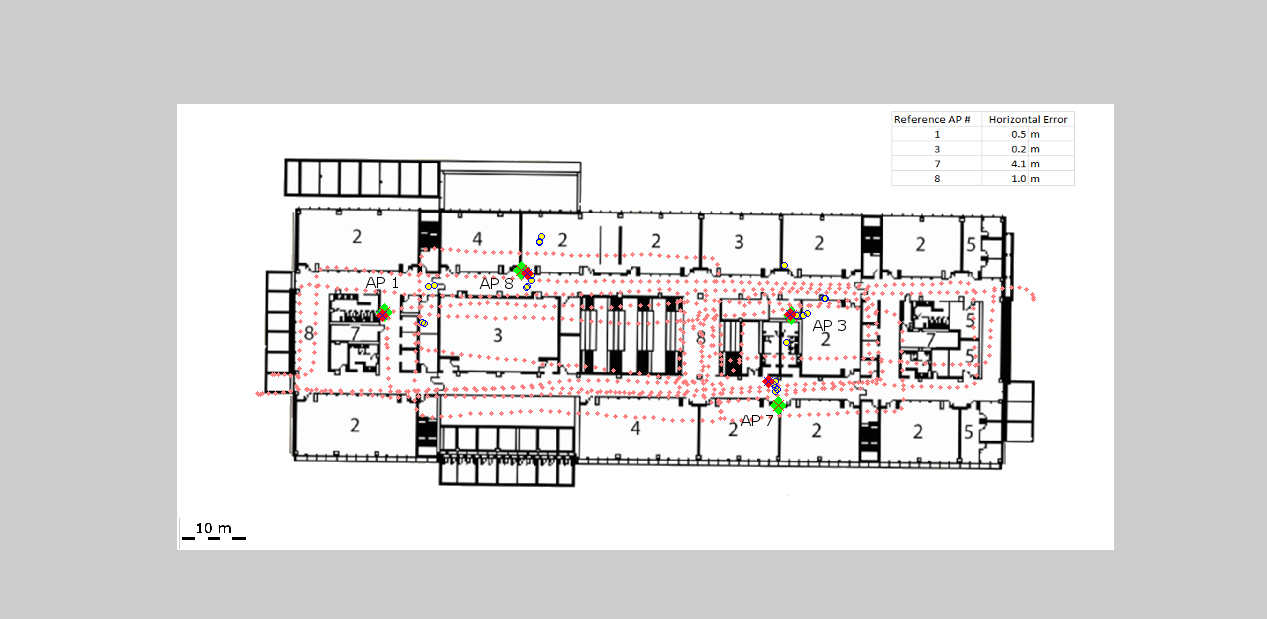
The problem with Wi-Fi is that the databases don’t stay totally reliable — so TPI solves this problem by also collecting data using other integrated sensors for positioning, which can then be used to update the very same Wi-Fi location data. This is one of the market areas that TPI believes it can access, since Wi-Fi positioning is becoming a more common navigation source. TPI would say Wi-Fi should be considered as only part of the solution, as it needs help from other sensors to work well.
Estimated Wi-Fi access point locations using sensors.
The Trusted Portable Navigator (T-PN) navigates while people walk or drive and use their cell phones in any orientation, anywhere and everywhere — including malls, airports or subways. T-PN combines the use of existing smartphone motion sensors with wireless updates (such as Wi-Fi and GNSS) for a complete solution with no extra hardware or infrastructure.
Over the last three years, TPI has developed an entire library of typical profiles for how people move and carry their cell phones. Algorithms detect particular movement profiles and then use appropriate filter adjustments to maintain or improve accuracy when in locations such as urban centers.
T-PN software has been released by TPI this year for integration in any mobile phone, tablet, or PC operating systems, with a view to capturing expanding mobile market applications, such as mobile advertising, indoor E-911, augmented reality, and fitness/recreation. Pedestrian navigation, navigation in parking garages, monitoring the location of devices in store displays, and assisting store visitors to find what they are looking for — all these potential applications are opportunities for TPI solutions. Therefore, TPI has so far chosen to market to mobile OEMs, MEMS and semiconductor manufacturers who can embed TPI software solutions in phones or in MEMS devices or components that go into these phones.
New technology areas that TPI is working on include wearables and using cameras as navigation sensors.
Now that a number of devices such as phones, watches, tablets, and (Google-like) glasses come with Bluetooth tethering, their movement can all be integrated to improve the navigation solution for people on the move.
TPI estimates that its sensor drift is approximately 4-8 percent of distance traveled when operating without any wireless updates. Chris Goodall calculates that adding multiple devices could improve overall accuracy of the navigation solution by up to threefold.
And how the heck do you use a camera as a navigation sensor without a massive visual database? Simple — just focus on a stationary object and calculate the turn rate of the camera/user. Not so easy, really, as continuously detecting stationary objects as the user moves sounds quite complex. How do you differentiate between objects moving and the camera/user moving? “Feature flow” over multiple images is apparently the answer in deriving velocity and turning rate. We’ll have to see when and how TPI will solve this problem and field a solution — but I suspect it may be very soon as TPI is apparently providing sneak-peak, hands-on demos at a number of upcoming trade shows this year.
Lots of companies are working on solutions to the indoor navigation problem, but as Goodall indicated, after first discussing things with TPI and then going off to try to do it themselves, people tend to come back to TPI. Its not as easy as it sounds, and it takes time and lots of trial and error to get anything that works, then making something that works reliably under all conditions is even harder. So TPI is now at the stage, with solutions that work well and work very reliably, that the company is are launching on consumer mobile phones and anticipate larger, mainstream deployments in 2014-2015. Look out for phones with TPI software in 2014 — and there is a rumor that the company may also make its software available to applications developers.
We’ll keep in touch with TPI and let you know from time to time as the company makes further inroads into this new market segment.
Trimble is adding to its airborne LiDAR portfolio with the Trimble AX60i and AX80. Both are highly capable, versatile systems that meet the demands of aerial survey operators for corridor and wide area mapping projects, Trimble said.
The new airborne systems, together with flight planning and analysis software tools, have been designed to provide rapid and efficient point cloud capture as well as high-resolution images and proven workflows with high productivity. The systems can be installed on either fixed wing or rotary aircraft.
Designed for low-altitude corridor mapping applications, the Trimble AX60i is an entry-level LiDAR system built on the same versatile platform as the high-altitude AX60 system, Trimble said. The platform allows AX60i users to upgrade to an AX60 in the future. The AX60i can be operated up to 5,000 feet above ground level (AGL) while offering a 400-kHz laser pulse repetition rate (PRR) with a single-channel, downward-looking laser.
The Trimble AX80 is a dual-channel LiDAR system that can be operated up to 15,500 feet AGL and is designed for the most demanding survey applications from high-altitude wide area mapping to detailed low-altitude corridor mapping. The AX80 offers an 800-kHz PRR with revolutionary forward- and backward-looking capability to enhance point density on the ground and improve image resolution. This two-dimensional oblique view offers unparalleled scanning of vertical facades of structures.
Trimble’s AX80 aerial imaging system.
An optional, fully-calibrated 80-Megapixel camera with forward motion compensation can be added to the AX60i and AX80 systems. The camera is integrated into the sensor head package and harmonized with the laser sub-system so that it does not need re-calibration each time the system is fitted to an aircraft.
These systems are optimized for precision applications, providing a uniform distribution of laser points across the entire field-of-view to widen the usable swath width. Operators can reduce track overlap or duplication, or fly at higher altitudes to achieve a given resolution. Together with a high-precision positioning system, integral power supplies and an in-flight monitoring tool, the Trimble AX60i and AX80 can allow operators to lower the complexity of airborne LIDAR surveys while increasing the quality of the output.
“The Trimble AX60i and AX80 systems extend our portfolio of aerial imaging solutions to meet a variety of mapping applications,” said Phil Sawarynski, business area director of Imaging Solutions for Trimble’s Geospatial Division. “They have been designed as true end-to-end solutions and are delivered with Trimble flight planning software and Trimble Inpho analysis software. Because everything is supplied by Trimble, operators can have confidence that the complete solution works together properly, and that the flight planning and post-mission analysis suites will enable them to provide a high-quality service to their customers.”
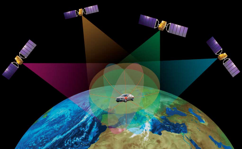
With the first Galileo services set to begin this year, the European Space Agency (ESA) is working directly with European manufacturers of mass-market satnav chips and receivers to ensure that their products are Galileo-ready.
“Our objective is to make sure, ahead of the European Union’s declaration of early Galileo services that mass-market devices are ready and able to make use of them,” explained Riccardo de Gaudenzi, head of ESA’s Radio Frequency Systems, Payload and Technology Division.
“In coordination with the European GNSS Agency, we put out an open call to satnav manufacturers offering testing with our laboratory facilities. We have gone on to work with five mass-market chipset makers and a comparable number of professional receivers manufacturers.”
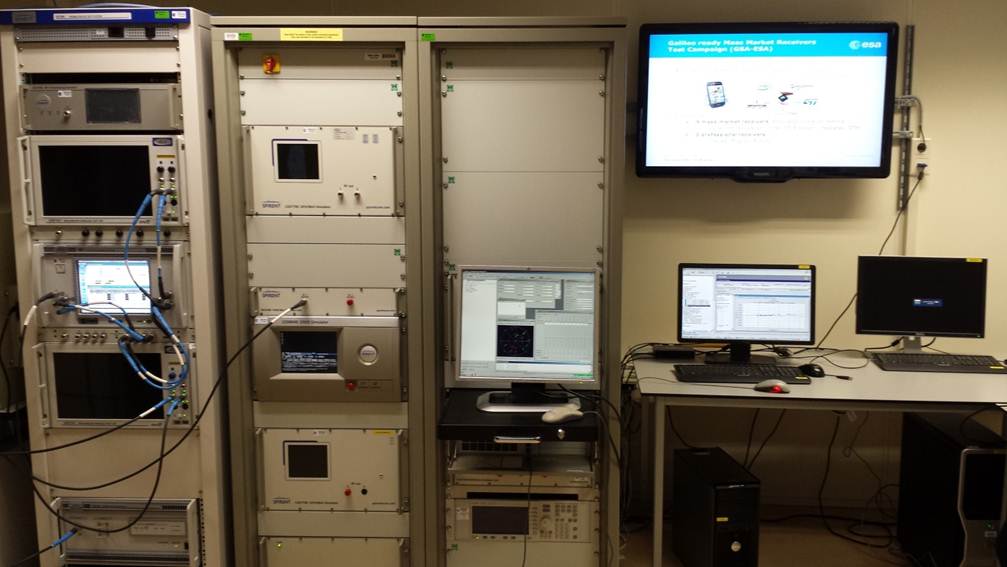
Key facilities being used at ESA’s Navigation Laboratory include its state-of-the-art “hybrid localization solution rack,” where receiver chips can be plugged in. This rack generates simulated constellations of Galileo, GPS and other satnav systems along with Wi-Fi or mobile networks which phone-based satnav chips often additionally employ. It can also simulate inputs from the kind of inbuilt gyro-type devices receivers employ for dead reckoning, to continue positioning measurements when satellites are out of view.
Hybrid localization solution rack.
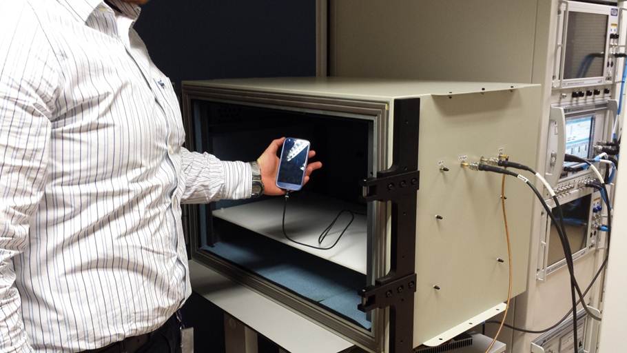
Another resource is the octobox — a mini anechoic chamber into which phones or mobile devices can be placed, to feed them simulated satnav and cellular network signals.
Octobox
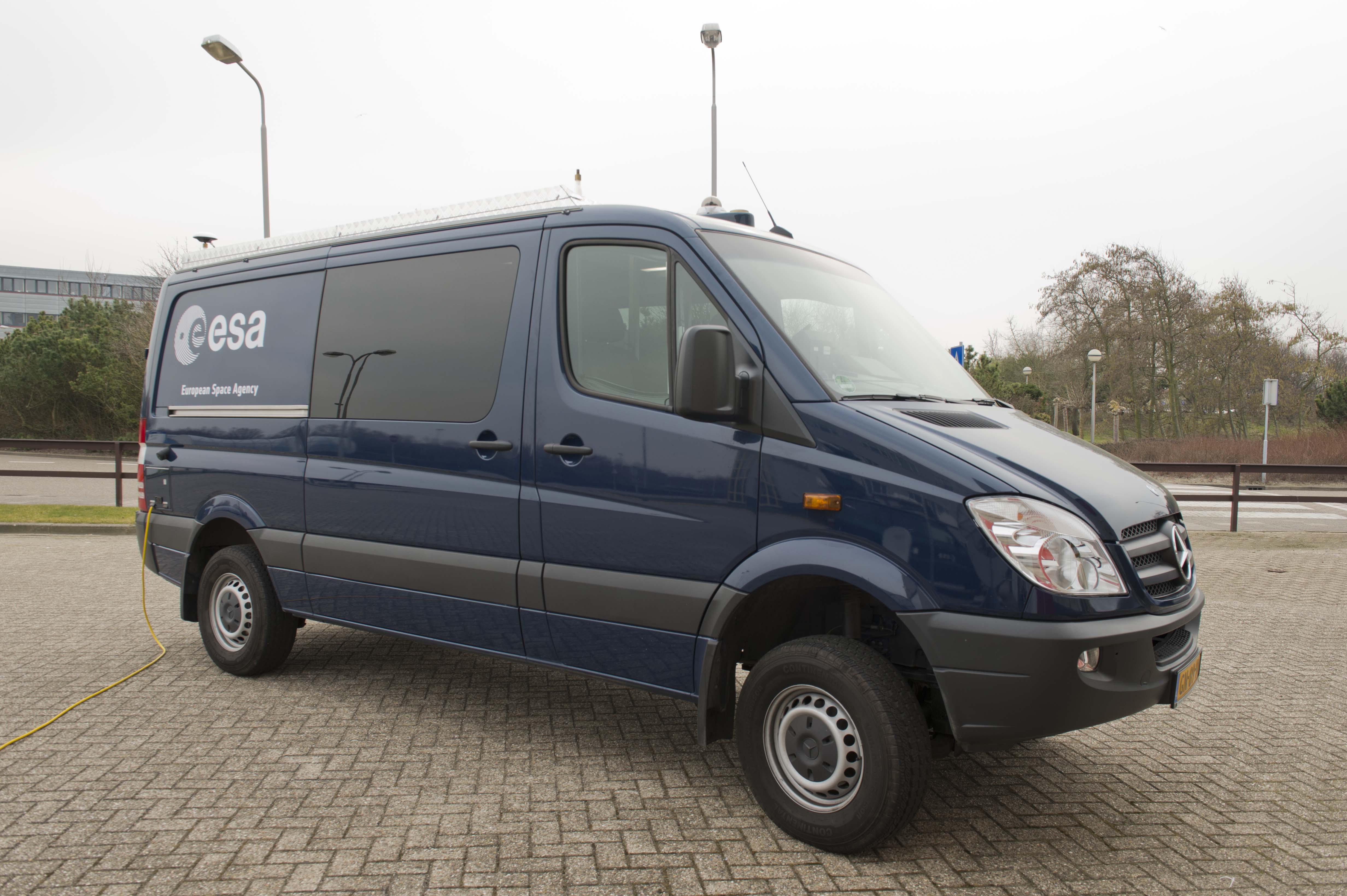
Testing in the field is carried out with the Lab’s Telecommunications and Navigation Testbed Vehicle. This fully equipped van carries its own extremely accurate receivers to assess the performance of the consumer items being tested.
Whether they are being used for vehicle navigation, shipment navigation, or precision agriculture, the performance of satnav terminals comes down to the specialized chips embedded within them. The same is true of mobile phones, although their chips tend to be optimized for low-power, high-sensitivity operations.Post
Test vehicle.
“This is a very useful initiative from our point of view, closing the loop between Galileo and industry,” commented Philip Mattos of ST Microelectronics, whose Teseo-2 receiver chips are used in satnavs and embedded in cars.
“Thanks to earlier collaboration with ESA and the EU, the millions of multi-constellation satnav chips we sell annually have been equipped for Galileo signals since 2009. It will take only a software update to enable them to start using Galileo,” Mattos said. “We have worked a lot with simulated Galileo signals, but this cooperation is allowing us to optimize our software based on access to actual signals and background technical information.”
Combining radio frequency and silicon elements, a single 1-cm square chip can detect signals from multiple satellite constellations — Russia’s GLONASS and China’s BeiDou as well as Galileo and GPS — then convert them into precise positioning measurements.
Beamed across thousands of kilometers of space, the signals are incredibly faint, barely distinguishable from background noise. But a technique called correlation gain synchronizes them with copies of each satellite’s broadcast code stored in the chip’s memory to boost them to usable levels.
Data from other systems, such as in-car accelerometers or gyros, can also be fed into the positioning measurements as desired.
For mass-market single-frequency designs, an ESA-created ionospheric model allows the subtraction of ionospheric delays, its performance coming close to dual-signal standards.
Chips also apply stored ephemerides data embedded in satellite signals — updates on where satellites are positioned in the sky — to speed up acquisition times.
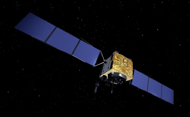
The first four Galileo satellites are already in orbit and operational. Over the course of 2014 six more satellites are planned to join them in three separate Soyuz launches. Galileo initial services are scheduled to start by the end of this year.
A contract to design and to deliver an advanced multi-GNSS constellation signal simulator and interface environment testbed was awarded by the European Space Agency (ESA) to IFEN GmbH on October 28, 2013. This contract is concluded in the context of the Signal Test Bed (SIGTB) activities of the European GNSS Evolution Programme (EGEP).
In addition to addressing the second generation of Galileo, which is planned to provide higher accuracy and signal robustness, the GNSS Signal Test Bed will include the following capabilities:
Flexible adaptability to all signal and message standards, whatever the future may bring.
Extensive investigation of intentional signal interferences.
Testing of GNSS signal performance in newly evolving standards.
Generation of even more realistic test scenarios that include background and intentional interference.
Refined scenarios of various distortions of GNSS signals.
Too Much Sensitivity, Not Enough Robustness, Says Parkinson
Brad Parkinson, the founding architect of GPS, told a UK conference that the system needs to be made more robust to ensure worldwide availability of services to users. His concerns over GPS availability relate to threats such as the loss of authorized frequency spectrum (implicitly creating licensed jammers), space weather due to hyperactive ionospheric conditions, and deliberate or inadvertent jamming of GPS signals.
He warned that GPS is more vulnerable to sabotage or disruption than ever before, and charged that politicians and security chiefs are ignoring the risk. Western governments are “in their infancy in recognizing the problem,” he remarked further in an interview with London’s Financial Times. “[In the United States] I don’t know anyone that is really in charge of it. The Department of Homeland Security should be [but] … they don’t have any people that understand it very well. They’ve got one person without any budget to speak of.”
He also warned that Europe’s €5 billion Galileo system is equally at risk.
Parkinson proposed a three-stage program to:
Protect (legally) the signal and physically eliminate jamming sources;
Toughen the GPS/Galileo receiver’s resistance to interference;
Augment the GPS signals with other satellites or with ground-based transmitters such as eLoran.
To support his proposal, Parkinson stated, “The number one need for all GPS or Galileo users is availability. Over the years, manufacturers of signal receiver technologies have focused too much on sensitivity and not enough on resilience or robustness. The maritime industry is a particular concern where users have taken GPS for granted. They must increase preparedness and backups as they do in aviation or other GNSS using industries.
“Even today, most ships have only GPS and the vision of their crew to guide them when approaching harbours. As you can see from today’s conference there are a wealth of solutions to toughen and backup GPS, many of which are not technologically difficult nor expensive, but still their adoption in sectors such as global shipping is certainly not adequate.”
As part of his protection program, Parkinson urged that penalties for jamming GPS networks be coordinated worldwide. “In Australia, if you cause interference likely to cause prejudice to the safe conduct of a vessel, it’s five years in the jug [jail] and $850,000.” Contrasting this with a U.S. case that may simply impose a forfeiture of the culprit’s jamming device, Parkinson added, “I’m calling for the community of nations to move to the Aussie-type penalties.”
In the toughening regard, Parkinson alluded to integration of GPS data with information derived from an inertial positioning system. “If you combine all of these things, a good set should be able to fly within 1 kilometer of a jammer with a 10-kilometer range,” said Parkinson. “That’s what I call toughening.”
Parkinson made his remarks as the keynote speech at GNSS Vulnerabilities and Resilient PNT 2014, hosted by the Royal Institute of Navigation. He will also deliver the keynote address, “Assured PNT: Assured World Economic Benefits,” for the European Navigation Conference on April 15 in the Netherlands.
The United Launch Alliance Delta 4 rocket family will launch a new GPS IIF satellite from Cape Canaveral Thursday night.
Liftoff is scheduled for Thursday at 8:40 p.m. EST, at the start of a 19-minute launch opportunity, according to the United Launch Alliance. The window is timed to deliver the GPS IIF-5 satellite directly into Plane A of the navigation network 11,000 miles above Earth.
GPS IIF-5 will replace the aging spacecraft known as GPS IIA-28 in Plane A, Slot 3 of the constellation. The GPS IIA-28 satellite was launched aboard Delta 249 on November 5, 1997, as the final member of the Block IIA series. It will go into a reserve role in the network for the remainder of its useful life.
This is the first of three GPS launches planned through July to replace aging craft in the constellation. GPS IIF-5 incrementally upgrades the constellation with improved accuracy, enhanced internal atomic clocks, better anti-jam resistance, a civil signal for commercial aviation, and a longer design life, all features of the Boeing-build Block IIF series. This will be the fifth of 12 Block IIF spacecraft being built to form the backbone of the GPS fleet for the next 15 years.
The Delta’s flight will last three hours and 33 minutes from liftoff until spacecraft separation, firing its cryogenic upper stage in three different burns to reach an initial parking orbit and taking a two-step transfer route to reach the circular GPS orbit tilted 55 degrees to the equator.
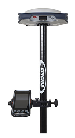
Spectra Precision introduced today its next-generation Spectra Precision SP80 GNSS receiver. Designed to meet the evolving needs of the survey market, the new SP80 combines GNSS technology and a combination of communication capabilities with an ergonomic design, the company said. The SP80 is specifically designed for mainstream surveying and construction applications such as cadastral, topographic, control, stakeout and network RTK.
Spectra Precision SP80 features Spectra Precision’s Z-Blade GNSS-centric technology running on a new-generation, 240-channel 6G chipset. The SP80 is capable of fully utilizing all six available GNSS systems (GPS, GLONASS, BeiDou, Galileo, QZSS and SBAS), but can also be configured to use only selected constellations in an RTK solution (GPS-only, GLONASS-only or BeiDou-only).The SP80 is also compliant with the new RTCM 3.2 standard, including the recently approved MSM RTCM messages, which means it supports all available GNSS corrections.
The extended communication capabilities of the SP80 receiver provide a combination of a 3.5G GSM/UMTS modem, Wi-Fi and Bluetooth connectivity, and an optional transmit UHF radio. The receiver’s built-in Wi-Fi and 3.5G modem can provide an Internet connection for RTK corrections and also send SMS or e-mails with system alerts. The SP80 features a unique anti-theft technology to safeguard the receiver and can detect if it is has been disturbed while in the field (for example, when operating as a GNSS base). The anti-theft protection feature informs the surveyor via SMS or e-mail if the SP80 receiver is moved and can provide its position to facilitate recovery.
The Spectra Precision SP80 is rugged and waterproof, yet compact, lightweight and ergonomic for ease of use in the field, Spectra Precision said. When the UHF transmit radio module is used, its UHF antenna remains protected inside the rugged rod, extending the radio range performance. Powered with dual hot-swap batteries for typical all-day operation, the SP80 receiver is an ideal tool for any surveyor.
“The Spectra Precision SP80 introduces several major enhancements and innovations, including the new 6G GNSS ASIC with enhanced Z-Blade technology, unique SMS and e-mail messaging and patented inside-the-rod mounted UHF antenna,” said Olivier Casabianca, business area director of Trimble’s Spectra Precision Division. “In addition, SP80 was designed as an extremely reliable receiver, making it suitable for a variety of challenging surveying projects.”
Wind generates electricity by turning the blades of turbines. Individual turbines can range in height from several dozen to several hundred meters tall, with blade lengths measuring several dozen meters. Image credit: USGS
Wind energy is one of the fastest-growing sectors of renewable energy in the United States. About 3% of the total electricity in the United States was generated by wind turbines in 2012 (according to the U.S. Energy Information Administration), which is equivalent to the annual electricity use for about 12 million households. The amount of electricity generated by wind has increased from about 6 billion kilowatt hours (kwh) in 2000 to 140 billion kwh in 2012.
In response to the Department of Interior’s Powering Our Future initiative, the U.S. Geological Survey (USGS) has begun investigating how to assess the impacts of wind energy development on wildlife at a national scale.
Assessment Experience
The USGS has extensive experience assessing energy resources, and it’s that expertise that makes the USGS qualified to assess nationwide impacts of wind energy development. One of the major reasons behind the success of USGS energy resource assessments is the scientifically robust methodology that underpins them.
USGS energy resource assessment methodologies are publicly available and are technically peer reviewed externally, and just as importantly, are used consistently in every assessment. That means that a USGS oil and gas assessment in Alaska provides comparable information to a USGS oil and gas assessment in Texas, or that a USGS geothermal assessment in California is comparable to a USGS geothermal assessment in Nevada.
A Different Kind of Assessment
USGS has recently undertaken a project to develop a methodology for assessing wind energy impacts on wildlife at a national scale. This research is different from previous USGS energy assessments. Instead of looking at technically recoverable resources of oil, gas, geothermal or coal, or even technically accessible storage areas for carbon sequestration, the USGS is developing a method for determining the impacts of a type of energy production. This work will merge the experience the USGS has creating assessment methodologies with its expertise in wildlife ecology and wind-wildlife research, as well as in land change science.
Wind turbines are often grouped together in facilities to maximize electricity-generating capacity. This image shows a wind farm on BLM land in California. Image credit: BLM
Wind energy can impact both wildlife and their habitats. Wildlife impacts include potential bird and bat mortality from collisions with turbine blades, and in some cases, species avoidance of habitat near turbines. Habitat impacts include the turbine pads in addition to service roads, transmission lines, substations, meteorological towers, and other structures associated with wind energy siting, generation, and transmission.
Turbine Locations
The first step in understanding the impact of wind energy development is to determine where the wind turbines are located. Prior to this study, there was no publicly available national-level data set of wind turbines. There were maps that showed turbines locations in a few states, and there were national-level maps that showed wind power facilities, but not individual turbines, or information about those turbines, such as height, blade length, or energy producing capacity.
A screenshot of the USGS WindFarm Mapping Application, which allows users to access the more than 47,000 individual wind turbines contained within the national wind turbine database. This view shows facilities in Southern California, color-coded for their wind-generating capacity. The red and yellow turbines have a higher electricity-generating capacity than the green and blue turbines do.
To remedy the lack of information, the USGS created this publicly available national dataset and interactive mapping application of wind turbines. This dataset is built with publicly available data, as well as searching for and identifying individual wind turbines using satellite imagery. The locations of all wind turbines, including the publicly available datasets, were visually verified with high-resolution remote imagery to within plus or minus 10 meters.
Knowing the location of individual turbines, as well as information such as the make, model, height, area of the turbine blades, and capacity creates new opportunities for research, and important information for land and resource management. For example, turbine-level data will improve scientists’ ability to study wildlife collisions, the wakes causes by wind turbines, the interaction between wind turbines and ground based radar, and how wind energy facilities overlap with migratory flyways.
Next Steps
In addition to the value this powerful tool has to Federal and State land managers, non-governmental organizations, the energy industry, scientists, and the public, it will be a useful component in the methodology that the USGS is developing for assessing wind energy impacts. The USGS is bringing together scientists with expertise in landscape-level science, wildlife biology, and other associated disciplines to create the methodology. Once developed, the methodology will be externally peer-reviewed and tested with pilot-level data projects. Once peer reviewed, the revised methodology will be published for others to understand and use.
Trimble has introduced the Juno T41 rugged handheld computer with integrated Ultra-High Frequency RFID capabilities. In addition to high-speed 1D/2D barcode imaging technology, smartphone capability and enhanced, real-time 1-2 meter GPS accuracy, the Juno T41 series now offers new models that provide more functionality and configuration choices for data collection and mobile workforce management, Trimble said.
“Often the RFID tag is specifically used because the item being tracked is in difficult or harsh environments where a barcode won’t survive,” said Jim Sheldon, general manager of Trimble’s Mobile Computing Solutions Division. “The rugged design of this handheld computer is an ideal solution for reading RFID in outdoor and extreme situations.”
The RFID capability can be combined with Enhanced GPS and/or smartphone connectivity so customers can choose a specific handheld model that meets their needs.
The Juno T41 R will automatically recognize tags across a variety of frequencies and work with any size or style of RFID tag that is designed for customized solutions. UHF RFID is an increasingly commonplace technology using the 860 to 960 MHz frequency range.
Using the latest EPCglobal Gen 2 RFID technology from Trimble’s ThingMagic Division, the device uses two different antenna ranges to read or recognize the unique identification of an asset anywhere in the world.
FCC Certified (North America): 902-928 MHz bands
ETSI Certified (EU): 865.6-867.6 MHz bands
ACMA Certified (AU/NZ): 920-926 MHz bands
Trimble Juno T41 RFID handheld computers feature a 1-GHz processor and 512-MB RAM and 32-GB onboard storage with either Android 4.1 or Microsoft WEHH 6.5 operating systems. Other standard features include an 8-MP integrated camera, multi-touch capacitive 4.3-inch sunlight-readable display, all-day battery life and 2-4 meter GPS accuracy capability. Other features include:
Rapid-read, high-accuracy performance on multiple tags with multiple orientations, even in crowded conditions.
Consistent read-range over 3.5 meters for 5 cm2 (2″) UHF tags in unobstructed space.
Integrated antenna with the ability to transmit up to +30 dBm (1 Watt) power for demanding applications.
>Configurable performance settings and use-case parameters in the pre-loaded Trimble SearchLight application.
Software Development Kit to customize all settings including read-range, power-consumption and other features.
The Juno T41 models are built to meet military-grade standards of ruggedness for drops, temperature, altitude, humidity extremes, vibration, chemical exposure and shock with either an IP65 or IP68 rating for water and dust.
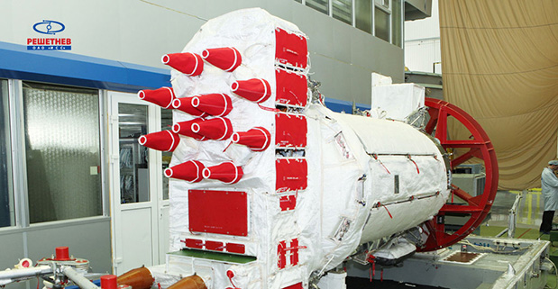
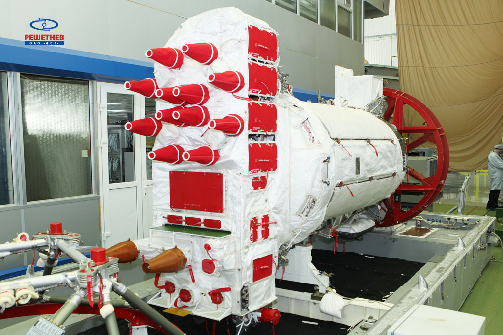
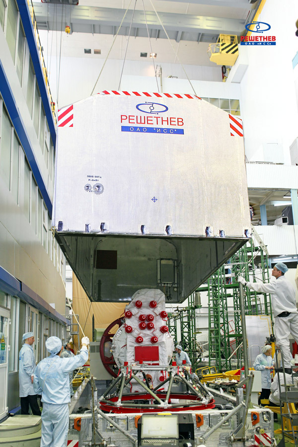
On the night of February 12-13, the GLONASS-M #54 spacecraft left ISS-Reshetnev’s facilities in Zheleznogorsk, Russia, and was transported by air to the Plesetsk cosmodrome.
A Soyuz 2.1b / Fregat rocket with the navigation satellite GLONASS-M #54 on board is scheduled for launch in mid-March. The exact launch date is due to be set at a meeting of the state commission.
As soon as the satellite arrived to the spaceport, the joint team of ISS-Reshetnev specialists and the cosmodrome’s staff members started the launch preparation campaign.
Five satellites of the GLONASS-M series are planned for launch in 2014 to maintain GLONASS in its full operational capability. Three satellites will be launched in a single batch, while the other two will fly into orbit in two single launches.
GLONASS-M #54 will also carry an additional instrument – a high-accuracy thermal stabilization unit that was installed on the spacecraft to undergo testing and flight qualification. Next-generation spacecraft intended for the GLONASS system are going to be equipped with this instrument to provide increased positioning accuracy.
Three more GLONASS-M spacecraft have already been built by ISS-Reshetnev and are being stored at the company’s premises waiting for launch.
Russia will deploy up to seven ground monitoring and augmentation stations for GLONASS outside of Russia, reports The Voice of Russia radio. GLONASS/GNSS Forum Association Executive Director Vladimir Klimov explained the plans at a conference.
“It is planned to deploy about six or seven stations on foreign territories this year,” Klimov said. Negotiations for the stations are now taking place with foreign nations, he said.
About 50 GLONASS ground stations are planned for construction. The stations will significantly improve GLONASS performance and provide efficient applications for high-precision navigation services and smooth monitoring of systems of coordinates and Earth rotation parameters, he said.
Currently, there are 46 GLONASS ground stations on Russian territory, eight in neighboring countries, three in Antarctica, and one in Brazil.