Blog

  • Quad-Constellation Receiver: GPS, GLONASS, Galileo, BeiDou

    The implementation changes and first live tests of BeiDou and Galileo on Teseo-3 GNSS chips developed in 2013 are covered, bringing it to a four-constellation machine. By 2020, we expect to have four global constellations all on the same band, giving us more than 100 satellites — under clear sky, as many as 30 or 40 simultaneously.

    By Philip G. Mattos and Fabio Pisoni

    Multi-constellation GNSS first became widely available in 2010/2011, but only as two constellations, GPS+GLONASS. Although receivers at that time may have supported Galileo, there were no usable satellites. BeiDou was a name only, as without a spec (an interface control document, or ICD), no receivers could be built. However, the hardware development time of receivers had been effectively shortened: the Galileo ICD had been available for years, BeiDou codes had been reverse-engineered by Grace Gao and colleagues at Stanford, and at the end of 2011 they were confirmed by the so-called test ICD, which allowed signal testing without yet releasing message characteristics or content.

    The last weeks of 2012 saw two great leaps forward for GNSS. Galileo IOV3 and 4 started transmitting at the beginning of December, bringing the constellation to four and making positioning possible for about two hours a day. At the end of December, the Chinese issued the BeiDou ICD, allowing the final steps of message decode and ephemeris calculation to be added to systems that had been tracking BeiDou for many months, and thus supporting positioning. The Teseo-2 receiver from STMicroelectronics has been available for some years, so apart from software development, it was just waiting for Galileo satellites; however, for BeiDou it needed hardware support in the form of an additional RF front end. Additionally, while it could support all four constellations, it could not support BeiDou and GPS/Galileo at the same time, as without the BeiDou ICD the spreading codes had to be software-generated and used from a memory-based code generator, thus blocking the GPS/Galileo part of the machine.

    The Teseo-3 receiver appeared late in 2013, returning to the optimum single-chip form factor: RF integrated with digital silicon and flash memory in the same package, enabling simultaneous use of BeiDou and GPS/Galileo signals. Multi-constellation in 2012 was GPS+GLONASS, which brought huge benefits in urban canyons with up to 20 visible satellites in an open sky. Now, for two hours a day in Europe while the Galileo IOVs are visible, we can run three constellations, and in the China region, GPS/BeiDou/Galileo is the preferred choice.

    This article covers the first tracking of four Galileo satellites on December 4, 2012, first positioning with Galileo, and first positioning with BeiDou in January 2013. It will cover static and road tests of each constellation individually and together as a single positioning solution. Road tests in the United States/Europe will combine GPS/GLONASS/Galileo, while tests in the China region will combine GPS/Galileo/BeiDou. Results will be discussed from a technical point of view, while the market future of multi-constellation hardware will also be considered.

    In the 2010–2020 timeframe, GLONASS and BeiDou (1602 MHz FDMA and 1561 MHz respectively) cost extra silicon in both RF and digital hardware, and cause marginal extra jamming vulnerability due to the 50 MHz bandwidth of the front end. The extra silicon also causes extra power consumption.

    After 2020, GLONASS is expected to have the L1OC signal operational, CDMA on the GPS/Galileo frequency, and BeiDou is expected both to have expanded worldwide, and also to have the B3 signal fully operational, again on 1575 MHz. At that point we will have four global constellations all on the same band, giving us more than 100 satellites. With a clear sky, the user might expect to see more than 30, sometimes 40, satellites simultaneously.

    Besides the performance benefits in terms of urban canyon availability and accuracy, this allows the receiver to be greatly simplified. While code generators will require great flexibility to generate any of the code families at will, the actual signal path will be greatly simplified: just one path in both RF (analog) and baseband (digital) processing, including all the notch filters, derotation, and so on. And this will greatly reduce the power consumption.

    Will the market want to take the benefit in power consumption and silicon area, or will it prefer to reuse those resources by becoming dual-frequency, adding also the lower-L-band signals, initially L5/E5, but possibly also L2/L3/L6 ? The current view is that the consumer receiver will go no further than L5/E5, but that the hooks will be built-in to allow the same silicon to be used in professional receivers also, or in L2C implementations to take advantage of the earlier availability of a full constellation of GPS-L2C rather than GPS-L5.

    This article presents both technical results of field trials of the quad-constellation receiver, and also the forward looking view of how receivers will grow through multi-frequency and shrink through the growing signal commonalities over this decade.

    History

    Galileo was put into the ST GPS/GNSS receiver hardware from 2006 to 2008, with a new RF and an FPGA-based baseband under the EU-funded GR-PosTer project. While a production baseband (Cartesio-plus) followed in high volume from 2009, in real life it was still plain GPS due to the absence of Galileo satellites.

    The changed characteristics in Galileo that drove hardware upgrades are shown in Figure 1. The binary offset carrier BOC(1,1) modulation stretches the bandwidth, affecting the RF, while both the BOC and the memory codes affect the baseband silicon in the code-generator area.
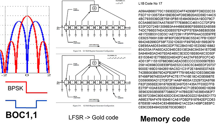
    Figure 1. Changes for Galileo.
    Figure 1. Changes for Galileo.

    Next was the return to strength of the GLONASS constellation, meaning receivers were actually needed before Galileo. However the different center frequency (1602 MHz), and the multi-channel nature of the FDMA meant more major changes to the hardware. As shown in Figure 2 in orange, a second mixer was added, with second IF path and A/D converter.
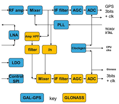
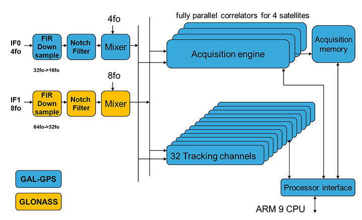
    Figure 2. Teseo-2 RF hardware changes for GLONASS.
    Figure 2. Teseo-2 RF hardware changes for GLONASS.
    Figure 3. Teseo-2 and Teseo-3 baseband changes for GLONASS.
    Figure 3. Teseo-2 and Teseo-3 baseband changes for GLONASS.

    The baseband changes added a second pre-processing chain and configured all the acquisition channels and tracking channels to flexibly select either input chain. Less visible, the code-generators were modified to support 511 chip codes and 511kchips/sec rates.

    Teseo-2 appeared with GPS/GLONASS support in 2010, and demonstrated the benefit of GNSS in urban canyons, as shown by the dilution of precision (DOP) plot for central London in Figure 4. The GPS-only receiver (in red) has frequent DOP excursions beyond limits, resulting either in bad accuracy or even interrupted fix availability. In contrast, the GNSS version (in blue) has a DOP generally below 1, with a single maximum of 1.4, and thus 100 percent availability. Tracking 16 satellites, even if many are via non-line-of-sight (NLOS) reflected paths, allows sophisticated elimination of distorted measurements but still continuous, and hence accurate, positioning.
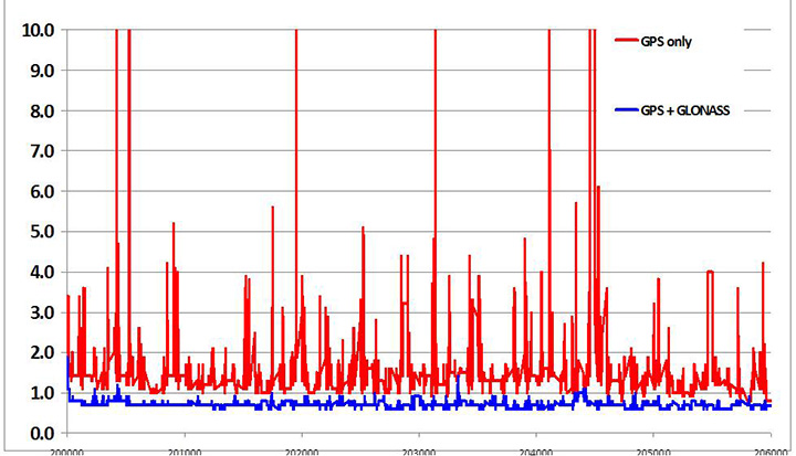
    Figure 4. DOP/accuracy benefits of GNSS.
    Figure 4. DOP/accuracy benefits of GNSS.

    BeiDou

    Like Galileo, BeiDou is a story of chapters. Chapter 1 was no ICD, and running on a demo dual-RF architecture as per the schematic shown in Figure 5. Chapter 2 was the same hardware with the test ICD, so all satellites, but still no positioning. Chapter 3 was the full ICD giving positioning in January 2013 (Figure 6), then running on the real Teseo-3 silicon in September 2013, shown in Figure 7.
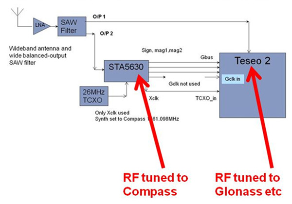
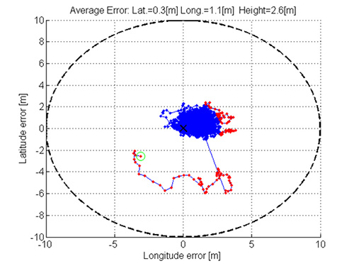
    Figure 5. Demo Teseo-2 dual RF implementation of BeiDou.
    Figure 5. Demo Teseo-2 dual RF implementation of BeiDou.
    Figure 6. Beidou positioning results.
    Figure 6. Beidou positioning results.
    Figure 7. Teseo 3 development board.
    Figure 7. Teseo 3 development board.

    The Teseo-3 has an on-chip RF section capable of GPS, Galileo, GLONASS and BeiDou, so no external RF is needed.

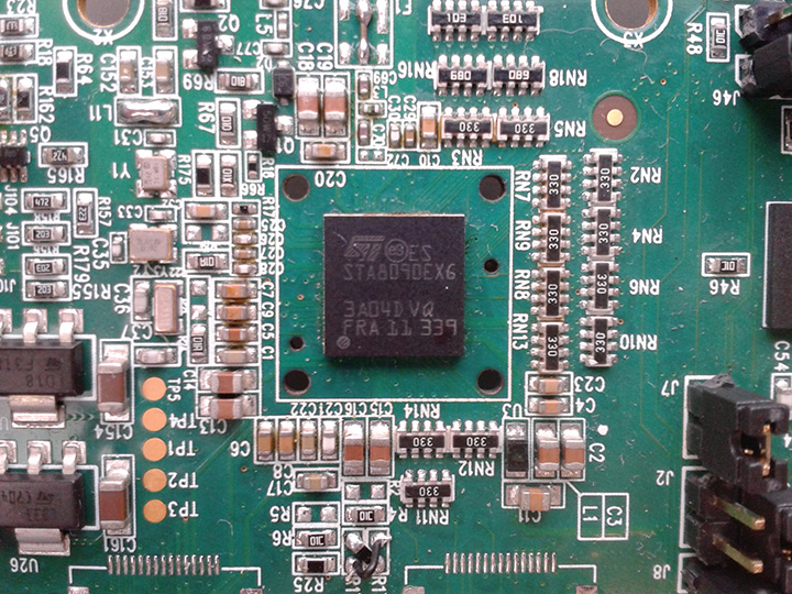
    The clear green space around the Teseo-3 chip in the photo and the four mounting holes are for the bolt-down socket used to hold chips during testing, while the chip shown is soldered directly to the board. Figure 8A shows the development board tracking eight BeiDou satellites visible from Taiwan.

    However, the silicon is not designed to be single-constellation; it is designed to use all the satellites in the sky. Figure 8b shows another test using GPS and BeiDou satellites simultaneously.
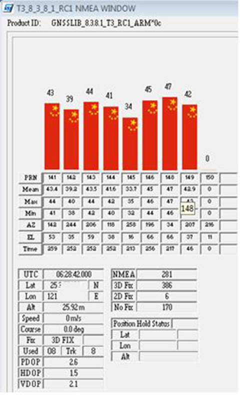
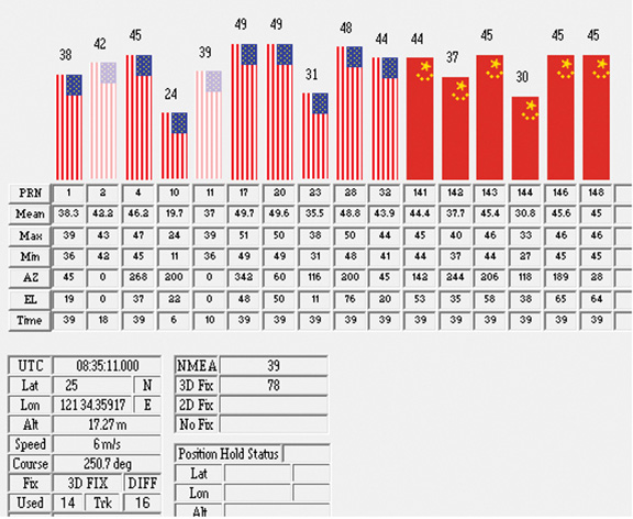
    Figure 8A. Beidou.
    Figure 8A. Beidou.
    Figure 8b. GPS+Beidou.
    Figure 8b. GPS+Beidou.

    A mobile demo on the Teseo-3 model is shown running GPS plus BeiDou in Figure 9, a road test in Taipei. Satellites (SV) up to 32 are GPS, those over 140 are BeiDou, in the status window shown: total 13 satellites in a high-rise city area, though many are non-LOS.
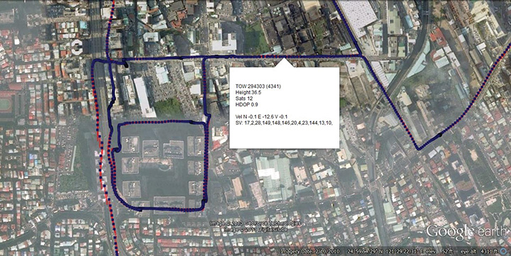
    Figure 9. GPS + Beidou roadtrack in Taipei.
    Figure 9. GPS + Beidou roadtrack in Taipei.

    Extending the hardware to add BeiDou, which is on 1561 MHz and thus a third center frequency, meant adding another path through the IF stages of the on-chip radio. After the first mixer, GPS is at 4 MHz, and GLONASS at about 30 MHz, but BeiDou is at minus 10 MHz. While the IF strip in general is real, rather than complex (IQ), the output of the mixer and input to the first filter stage is complex, and thus can discriminate between positive frequencies (from the upper sideband) and negative ones (from the lower sideband), and this is normally used to give good image rejection. In the case of BeiDou, the filter input is modified to take the lower sideband, that is, negative frequencies, and a second mixer is not required; the IF filter is tuned to 10 MHz. The new blocks for BeiDou are shown in green in Figure 10. The baseband has no new blocks, but the code generator has been modified to generate the BeiDou codes (and, in fact, made flexible to generate many other code types and lengths). Two forms of Teseo-3 baseband are envisaged, the first being for low-cost, low-current continues to have two input paths, so must choose between GLONASS and BeiDou as required. A future high-end model may have an extra input processing path to allow use of BeiDou and GLONASS simultaneously.
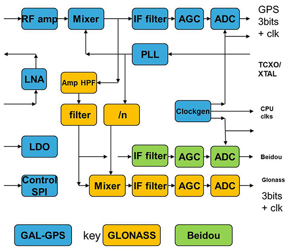
    Figure 10. Teseo-3 RF changes for Beidou shown in green.
    Figure 10. Teseo-3 RF changes for Beidou shown in green.

    Galileo Again

    Maintaining the chronological sequence, Galileo gets a second chapter in three steps. In December 2012, it was possible for the first time to track four IOV satellites simultaneously, though not to position due to the absence of valid orbit data. In March 2012, it was possible for the first time to demonstrate live positioning, and this was done using Teseo-2 simultaneously by ESA at ESTEC and STMicro in Naples and Milan, our software development centres.

    The demos were repeated in public for the press on July 24, 2013, at Fucino, Italy’s satellite earth station, with ESA/EC using the test user receiver (TUR) from Septentrio, and ST running simultaneous tests at its Italian labs. Figure 11 and Figure 12 show the position results for the data and pilot channels respectively, with independent LMS fixes. In real life, the fixes would be from a Kalman filter, and would be from a combined E1-B/E1-C channel, to take advantage of the better tracking on the pilot.
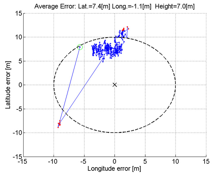
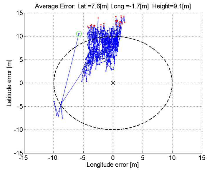
    Figure 11. Galileo positioning, E1-B.
    Figure 11. Galileo positioning, E1-B.
    Figure 12. Galileo positioning, E1-C.
    Figure 12. Galileo positioning, E1-C.

    Good accuracy is not expected from Galileo at this stage. The four satellites, while orbited to give good common visibility, do not also give a good DOP; the full set of ground monitoring stations is not yet implemented and cannot be well calibrated with such a small constellation. Finally, the ionospheric correction data is not yet available. Despite these problems, the residuals on the solutions, against a known fixed position for the rooftop antenna, are very respectable, shown in Figure 13.
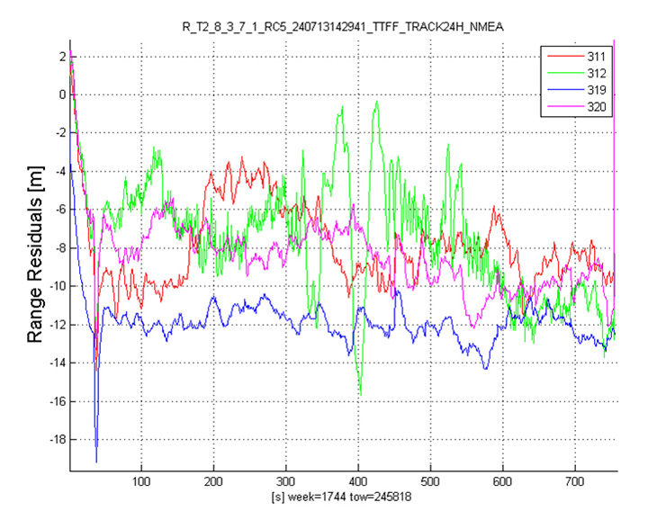
    Figure 13. Galileo residuals, L1-B.
    Figure 13. Galileo residuals, L1-B.

    The common mode value is unimportant, representing only an offset in the receiver clock, and 10 meters is about 30 nanoseconds. The accuracy indicator is the spread between satellites, which is very respectable for a code-only receiver without full iono correction, especially around 640 on the TOW scale, where it is less than 2 meters. The rapid and major variation on the green data around t=400 is considered to be multipath, as the roof antenna is not ideally positioned with respect to other machinery and equipment also installed on the roof.

    QZSS and GPS-III/L1C

    Teseo-2 has supported the legacy (C/A code) signal on QZSS for some time, but Teseo-3 has been upgraded to handle the GPS-III/L1-C signal, waiting for modernized GPS. This signal is already available on the QZSS satellite, allowing tests with real signals. Significant changes were required in the baseband hardware, as the spreading code is a Weill code, whose generation complexity is such that it is generated once when the satellite is selected, then replayed real time from memory. Additionally it is long, in two domains. It is 10230 chips — that is, long to store but also long in time, with a 10-millisecond epoch. On Teseo-3, the legacy C/A code is used to determine code-phase and frequency before handing over to the Weill code for tracking.

    Using a long-range crystal ball and looking far into the future, a model of the future Teseo-4 DSP hardware is available, with 64 correlation taps per satellite. Running this on the captured QZSS L1-C signal gives the correlation response shown in Figure 14. Having multiple taps removes all ambiguity from the BOC signal, simultaneously removing data transitions, which can alternatively be pre-stripped using the known pilot secondary code (which on GPS III is 5 dB stronger than the data signal). The resultant plot represents 2,000 epochs, each of 10 milliseconds, plotted in blue, with integrated result for the full 20 seconds shown in the black dashed line. Assuming vehicle dynamics is taken out using carrier Doppler, this allows extremely precise measurement of the code phase, or analysis of any multipath in order to remove it. This RF data was captured on a benign site with a static antenna, so it shows little distortion.
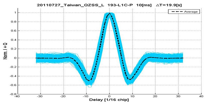
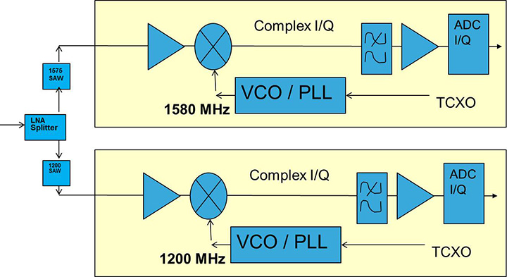
    Figure 14. L1-C tracking on QZSS satellite.
    Figure 14. L1-C tracking on QZSS satellite.
    Figure 15. Dual RF implementation of dual-band front end.
    Figure 15. Dual RF implementation of dual-band front end.

    The Future

    Having already built in extreme flexibility to the code generators to support all known signals and generalized likely future ones, the main step for the future is to support multiple frequencies, starting with adding L5 and/or L2, but as before, ensuring that enough flexibility is built in to allow any rational user/customer choice. It is not viable for us to make silicon for low-volume combinations, nor to divide the overall market over different chips. Thus our mainstream chip must also support the lower volume options.

    We cannot, however, impose silicon area or power consumption penalties on the high-volume customer, or he will not buy our product.

    Thus, our solution to multi-frequency is to make an RF that can support either band switchably, with the high band integrated on the volume single-chip GNSS. Customers who also need the low band can then add a second RF of identical design externally, connected to the expansion port on the baseband, which has always existed for diagnostic purposes, and was how BeiDou was demonstrated on T2. By being an RF of identical design to the internal one, it incurs no extra design effort, and would probably be produced anyway as a test chip during the development of the integrated single-chip version. Without this approach, the low volume of sales of a dual-band radio, or a low-band radio, would never repay its development costs.

    Conclusions

    All four constellations have been demonstrated with live satellite signals on Teseo-2, a high-volume production chip for several years, and on Teseo-3 including use in combinations as a single multi-constellation positioning solution. With the advent of Teseo-3, with optimized BeiDou processing and hardware support for GPS-3/L1C, a long-term single-chip solution is offered.

    For the future, dual-frequency solutions are in the pipeline, allowing full advantage of carrier phase, and research into moving precise point positioning and real-time kinematic into the automotive market for fields such as advanced driver-assistance systems.

    Acknowledgments

    Teseo III design and development is supported by the  European Commission HIMALAYA FP-7 project.

    This article is based on a technical paper first presented at ION-GNSS+ 2013 in Nashville, Tennessee.

    ST GPS products, chipsets and software, baseband and RF are developed by a distributed team in: Bristol, UK (system R&D, software R&D; Milan, Italy (Silicon implementation, algorithm modelling and verification); Naples, Italy (software implementation and validation); Catania, Sicily, Italy (Galileo software, RF design and production); Noida, India (verification and FPGA). The contribution of all these teams is gratefully acknowledged.


    Philip G. Mattos received an external Ph.D. on his GPS work from Bristol University. Since 1989 he has worked exclusively on GNSS implementations, RF, baseband and applications. He is consulting on the next-generation GNSS chips, including one-chip GPS (RF+digital), and high-sensitivity GPS and Galileo for indoor applications, and combined GPS/Galileo/GLONASS chipsets. In 2008-2009, he re-implemented LORAN on the GPS CPU, and in 2009-2010 led the GLONASS implementation team. He is leading the team on L1C and BeiDou implementation, and the creation of totally generic hardware that can handle even future unknown systems.

    Fabio Pisoni has been with the GNSS System Team at STMicroelectronics since 2009. He received a master’s degree in electronics from Politecnico di Milano, Italy, in 1994. He was previously with the GNSS DSP and System Team in Nemerix SA and has earlier working experience in communications (multi-carrier receivers).

  • The Business — January 2014

    The Business section from the January 2014 issue (Download the PDF).

    Includes: Raytheon Receives $16M Contract  for Miniaturized Airborne Receivers; Loctronix Ships Software-Defined Radio Module; Amazon Demonstrates Drone Deliver; CHC Delivers 520 Receivers in Myanmar Contract; Qualcomm Chipset Offers 4G LTE World Mode; u-blox Launches Timing Module; Broadcom Offers Location Chip with BeiDou Support; more.

  • Expert Advice: The Low Cost of Protecting America

    Dana A. Goward
    Dana A. Goward

    By Dana A. Goward

    Highly precise and free for use by anyone with an inexpensive receiver, GPS and other GNSS are great. Their navigation and timing signals have been incorporated into nearly every aspect of modern life, from synchronizing power grids to financial systems, the Internet, telecommunications, and transportation. The U.S. Department of Homeland Security estimates that these signals are used by all 16 of U.S. critical national infrastructure sectors, and are essential to the functioning of 11.

    Jamming Threat Growing. When these faint signals can’t be received, people start to feel the impact immediately. Usually outages have minimal impact because they are localized and short-lived. Often they occur because the user is temporarily in an area without a good view of the sky. More and more often, though, they are due to the presence of one of a growing number of people with jamming devices (many of which also block cell phone frequencies).

    Inexpensive, easy to obtain, and illegal, jammers are spreading as people become more concerned about privacy and being tracked by their employer, spouse, the National Security Agency, and others. Although the government tries to collect information on jamming incidents, no widespread detection system has been established, and few verbal reports are received. For the calls that do come in, it is often impossible to determine which are because of user error and which are purposeful interference.

    For those cases where jamming is discovered, locating and identifying the perpetrator is difficult and often impossible. As one example, in spite of near-daily disruption of GPS that caused the shutdown of a new landing system at Newark International Airport, it took the Federal Aviation Administration and the Federal Communications Commission more than two years of concerted effort to identify the single perpetrator.

    If a navigation satellite outage became widespread and lasted more than a few hours because of a major solar flare, software problem, hacker or cyber-attack, most authorities agree that the impacts would be catastrophic. While much of the information is classified, we do know that transportation would immediately become much less efficient and more dangerous; even many traffic lights are coordinated using satellite timing. Telecommunications, financial, energy and other systems would soon begin to fail as their back-up timing systems lost synchronization with each other. Power grids would lose synchronizations and outages may occur as transmission points became overloaded.

    More than speculation, these problems have been documented in academic papers, proven in government tests in the United States and the United Kingdom, and the early stages of such impacts have been observed in localized and short-term outages in the United States. Most dramatically, they have been demonstrated by North Korea’s intentional jamming of South Korea.

    Spoofing. Of equal concern is the problem of spoofing. The world’s preeminent ethical spoofer of satellite navigation receivers, Todd Humphreys of the University of Texas, Austin, has demonstrated how easy it is to take control of unmanned aircraft and ships on autopilot by sending a slightly stronger navigation signal, making the receiver think it is somewhere other than where it is. Iran claims to have done something similar, capturing a U.S. military drone in 2010. Humphreys has also shown (on paper) how time-stamps on automated financial transactions could be altered through spoofing. This could do things like reverse the buy-sell equation at a stock exchange, allowing someone to sell at a higher price before buying at a lower one.

    The Government Solution

    What is to be done? The challenges have been extensively documented and discussed since at least the 1990s. In 2004, President Bush issued the National Space Policy (NSPD-39) that addressed the problem. Although portions of it are still classified, contained within the publically releasable section was direction for the U.S. Department of Transportation (DOT) to, in coordination with the Department Homeland Security (DHS): “develop, acquire, operate, and maintain backup position, navigation, and timing capabilities that can support critical transportation, homeland security, and other critical civil and commercial infrastructure applications within the United States, in the event of a disruption of … space-based positioning, navigation, and timing services.”

    eLoran Recommended. In response, the two departments consulted numerous experts and commissioned a study by the Institute for Defense Analysis (IDA) to determine what system or systems should be procured. The IDA study team, which included Brad Parkinson, widely recognized as the father of GPS, unanimously recommended that an existing and outdated nation-wide navigation system called Loran-C be greatly updated and modernized to eLoran. Such a system would provide a navigation and timing signal comparable with and complementary to GPS. They concluded that:

    “eLoran is the only cost-effective backup for national needs; it is completely interoperable with and independent of GPS, with different propagation and failure mechanisms, plus significantly superior robustness to radio frequency interference and jamming. It is a seamless backup, and its use will deter threats to US national and economic security by disrupting (jamming) GPS reception.”

    What the IDA did not find, but that has since become evident, is that establishing an eLoran system could be an important part of a network to identify and locate jamming attempts. Since all eLoran transmitters would be synchronized with GPS, and many navigation receivers would have both GPS and eLoran sensors, differences between the two systems could be immediately detected and reported.

    The body in charge of coordinating navigation and timing issues for the federal government is the National Space-Based Position Navigation and Timing Executive Committee (NPEC). It is chaired by the Deputy Secretaries of Transportation and Defense. Responding to early briefings on the IDA report (which was not formally published until 2009), the Departments of Transportation and Homeland Security in 2007 told the NPEC that they had decided eLoran was the right answer. After further federal deliberations over how to create an eLoran system, 2008 saw:

    • A press release by DHS saying that the department would implement eLoran, using the old Loran-C infrastructure (February 7, 2008)
    • The DHS 2009 Budget in Brief (February 2008) propose transferring legacy Loran-C systems and $34.5 million/year from Coast Guard to the National Protection & Programs Directorate (NPPD) within DHS, stating:

    “The FY 2009 budget transfers the budget authority for the LORAN C system from the United Sates Coast Guard to the NPPD. The Department, acting as Executive Agent, will begin development of enhanced eLORAN as a backup for GPS in the homeland.”

    • The National PNT Executive Committee endorse the above decisions (March 2008).

    Failure to Launch

    Unfortunately, DHS funding for 2009 came as part of a continuing resolution, and the Congress did not see fit to approve the transfer of funds from Coast Guard to NPPD.

    This was because influential members of Congress wanted the nation to have eLoran, but were concerned about the lack of a plan for transition of this important capability from one agency to another. The administration was asked to develop and submit a plan with with the next budget cycle. A year later, though, no plan had been presented, and the President’s request (and enacted legislation) for 2010 contained no request to move and upgrade the system. In fact, it contained provisions for shutting down and defunding the old Loran-C system without providing funds for NPPD or any other agency to establish the new eLoran capability.

    No Solution at All. What happened between one budget year and the next to take the nation from “solution-in-hand” to “no solution at all” is not a matter of public record. Internal administration budget deliberations are not generally released to the public. It does appear, though, that a new administration putting together its first real budget quite rightly wanted to shut down an antiquated system, but did not understand the importance of a new one. This, and many other factors, unquestionably played a role.

    Movement Backward

    Without any funding, DHS has since conducted several studies and experiments, but has done very little of substance to address this critical infrastructure issue. While Department of Defense (DOD) officials talk about the need for resilience, experts throughout government and industry decry the lack of action, and the Department of Transportation still has acquiring “backup position, navigation, and timing capabilities” on its to-do list, none have seen fit to move forward on their own.

    Felling Towers. Worse, DHS is actually reducing the nation’s ability to create eLoran and a wide-area interference detection and mitigation system. An ongoing effort to fell towers and dispose of equipment from the legacy Loran-C system will significantly increase the cost and time-to-operation of the new system the nation needs.

    The Way Forward

    Fortunately, awareness and understanding of the problem within government, and the general public has continued to grow.

    The U.S. National Space-Based Positioning, Navigation, and Timing (PNT) Advisory Board published a seminal white paper in 2010 on the topic, strongly recommending the establishment of an eLoran system. Todd Humphreys, the UK navigation authority, and others have provided numerous graphic demonstrations of the folly of relying upon just one electronic navigation system, and how things can go horribly wrong. Some of these have been well publicized. Other incidents are known only to a few.

    There are also signs that the U.S. intelligence, cyber, and defense communities are becoming more and more concerned. North Korea’s repeated jamming of satellite navigation and timing signals has delivered a particularly powerful lesson. South Korea has reacted by committing to establishment of a robust eLoran system. The UK has established an eLoran system and is expanding it. Russia and China have retained their versions of Loran-C and are using it to augment satellite services. Russia has announced it will upgrade its system to eLoran in cooperation with the UK, and China may not be far behind. Saudi Arabia is upgrading its system to eLoran, and India has plans for an eLoran network in the near future. In December, Iran announced it has established a land-based system with “powerful transmitters” that is “completely different with GPS.”

    Allies, adversaries, and economic competitors are augmenting satellite services with strong terrestrial ones. The United States will soon be one of only a small number of major economies that does not have a strong, difficult-to-disrupt terrestrial system protecting its critical infrastructure and providing value-added utilities. DOD’s chief information officer expressed interest in eLoran as part of DOD’s pivot to the Pacific. But providing a system at home is not in Defense’s job description, nor should it be.

    Respected leaders at the Departments of Transportation and Homeland Security still see this as an important issue that needs to be addressed. The question for them now is not one of technology. The technology decision made in 2008 has since been revalidated by a plethora of academic papers, risk estimates, and white papers. eLoran still appears to be the most effective and least expensive solution available. DOT and DHS must resolve questions of governance and how to fund the system in one of the most difficult federal budgetary climates in decades.

    How? The answer could lie in a public-private partnership (P3). In such an arrangement, the government would bring its interests and the infrastructure it owns to the table. An entity in the non-profit sector or industry would provide investment to refurbish the infrastructure, stand up, and operate the system. Such a P3 enterprise could not only pay for itself, but be an on-going source of revenue for both the government and the private entity.

    The Business Model: Demand

    A well-configured eLoran system can provide navigation accuracy to within 8 to 10 meters and timing accuracy to within 30 nanoseconds. This meets the needs of an estimated 95 percent of users in the United States. While eLoran does not offer the sub-meter precision of a high end, augmented GPS/GNSS system, it has its own advantages. In addition to being very difficult to disrupt, its high-power (typically 400 kW transmitters), low-frequency (100 kHz) signal easily penetrates and is usable underground, inside buildings, and underwater — where satellite and cell phone signals on much higher frequencies cannot reach.

    The UK experience with eLoran and private surveys in the United States have shown high commercial demand for a ubiquitous, wireless, precise, and resilient time and navigation service. Power companies want to synchronize grids with a signal that can’t be disrupted by a delivery driver trying to avoid being tracked by his boss. Cell phone companies would be happy to have alternative timing capability in their networks, provided through inexpensive eLoran receivers. Operators of autonomous vehicles want a robust navigation signal and guaranteed communications. And it would be welcomed by the many users who, research shows, rely upon GPS/GNSS time for mission-critical applications, and who have no secondary source on which to fall back in the event of a disruption.

    Since eLoran easily penetrates inside buildings, underground, and underwater, it can be used for timing and navigation in many places where no other navigation and timing sources are available. For example, it has been used for underground and underwater navigation. When paired with an accurate satellite signal before going underground or submerging, eLoran could enable a navigation receiver to maintain a comparable level of precision for several hours. Even after that, it would provide the navigator an accurate underground/underwater compass, and a good position.

    The eLoran navigation and timing system now in operation in the United Kingdom also generates revenue by transmitting data. While the full potential of this third-party data-channel capability is still being explored, the ability to assure data delivery to, and communicate with such areas is appealing to many commercial and government organizations. Potential first-responders and commercial benefits appear almost limitless.

    The Business Model: Costs

    The cost for the P3 to standup and operate an eLoran system in the United States would be exceptionally low. Most of the needed infrastructure is already owned by the federal government in the form of the sites for the shuttered Loran-C system. Many of these still have transmission towers and other equipment that could be repurposed. Re-using this infrastructure and equipment would greatly reduce both the time and expense needed, compared to standing up the new system from scratch.

    Operating and maintenance costs would also be low. Solid-state equipment, remote monitoring, and other advances in technology make the process of re-establishing a transmission site fairly inexpensive. Today’s eLoran transmitting site consists of a tower, an equipment enclosure for the transmitter, a fence, and a backup generator. With only a modest investment to refurbish existing infrastructure, regular outlays to service capital debt would be minimal, at best.

    Some estimates predict that a terrestrial precise navigation and timing system, such as the one established in the United Kingdom and the one up for contract by South Korea, could be established in the continental United States within three years and for approximately $40 million, if the existing infrastructure were repurposed. Operating costs are estimated at approximately $16 million per year.

    Business Model: Revenues

    Significant national and homeland security concerns, high demand, and low cost (especially compared to any government space program) — clearly, but for a series of unfortunate bureaucratic reasons, eLoran would have been established in the United States, probably as a government-owned and operated system, long ago.

    But high demand and low cost are also excellent ingredients for a business enterprise, provided there are sources of revenue. An eLoran P3 could have multiple sources of revenue. Depending upon the type of partnership and business model(s) the government selected, surplus revenue could also be generated to help fund other programs or offset the deficit. Some of the possibilities include:

    ◾    Guaranteed Delivery Data Transmission. As mentioned earlier, eLoran’s high power and low frequency mean that the signal penetrates where few others will. In addition to navigation and timing information, which are inherent in the basic signal, low-rate data can also be included between the primary pulses. The highest demonstrated data transfer rate to date has been 1300 bps, which is fine for texting and issuing commands. Many believe that, with a modicum of research, that rate can be much higher. As the owner of the high-power transmitter network, the P3 would generate revenue the same as any telecommunications provider: by charging per message or for time on the network.

    Applications could include:

    • Assured wireless control of remote equipment and vehicles, including indoors, underground and underwater;
    • Information delivery to first responders and other crews regardless of location — especially good for pre-programmed emergency and operational commands to evacuate, use another procedure, and so on.
    • Immediate device updates and reprogramming. The ability to reach all of the enabled devices on a given network at the speed of light and virtually simultaneously has unlimited potential.

    ◾    PNT Interference Detection and Monitoring. One of the biggest challenges to countering jamming satellite navigation and timing signals is the lack of a detection network. The eLoran transmitter and receiver network will continuously synchronize with GPS/GNSS signals and instantly detect when differences between the two dissimilar systems occur. Instant reports could be generated to inform federal, state, and local authorities of the anomalies and their locations. Mobile disruptors could even be tracked as they drove down the highway, sailed through the port, or flew across the sky. The P3 could generate revenue by contracting to provide such information to private parties and government agencies concerned about interference incidents.

    ◾    Licensing Receivers. One of the simplest ways to generate revenue and endow the P3 would be for the government to assess a small fee on every eLoran and satellite navigation receiver sold in the United States. A one dollar fee per unit could generate more than $20 million per year and fund operation of the entire system. Such a fee could be discontinued as other sources of revenue from the system made it unnecessary.

    ◾    Broad-based User Fees. Since navigation and timing signals are essential to so much U.S. critical infrastructure, a case could be made that the cost to endow the P3 should be spread as broadly as possible across the technologies it supports. For example, a temporary 8-cent fee on every monthly U.S. cell phone and electric bill for just one year could provide enough funding to endow the P3 in perpetuity.

    ◾    Value-Added Services For High-End Users. More than 90 percent of the users of precise time in the United States require it at the microsecond (1,000 nanoseconds) level of accuracy. eLoran can provide a signal accurate to 30 nanoseconds. To achieve that level of precision, the eLoran network transmits data that compensates for low-frequency signal propagation over non-homogenous terrain. This correction data could be encrypted. Most users would access the signal at the microsecond level of accuracy for free. Revenue could be generated by charging those who desire the higher level of precision a fee for the encrypted portion of the signal.

    eLoran is an essential national and homeland security capability. The above list of potential revenue sources is just a sampling of the many ways a P3 could be funded. The point is that financing the enterprise need not come from tax dollars, and should not be an obstacle to its creation.

    The Public-Private-Partnership

    The U.S. government has had some great successes solving previously intractable problems through public-private-partnerships. Probably the best known of these are the P3s formed for housing on military bases. Establishing a business model that has private partners constructing and managing on-base housing produced more and higher quality housing for our troops.

    Such arragnements must be carefully managed, however.  Both the Congressional Budge Office and the Office of Management and Budget are understandably concerned that P3s may get a project going, but soon the costs may fall entirely on the government.

    Success in any endeavor often depends upon its execution. The type of partnership the government selects and creates will be key. While, at its heart, a P3 is just a contract, the nature and provisions of government contracts are endlessly varied. Issues to address will include how the infrastructure is provided, if it is to be retained in perpetuity by the government or will be conveyed to the private party, what length of contract will allow the private partner to recoup its initial investment, and the business model(s) to be pursued.

    The type of governance will also be important. Models vary from establishment of a self-funded government corporation to oversee daily operations, to an agency-supervised, performance-based contract that only requires regular reports on system availability and performance.

    Of course, the concerns of CBO and OMB must be met. Fortunately, the federal government is not without experience with P3s. Also, there are many supporting resources available, such as the National Council for Public Private Partnerships.

    We Have to Do It

    Establishing a public-private partnership will bring together the best of both the government and the private sector. For its part, the government will bring the legacy infrastructure and its interest in safeguarding the public good to the table. The private sector will bring financing, technical know-how and innovation. A better system for America will result than would have been possible if either were to act alone.

    It is unquestionably in our urgent national interest to address the problem now, before jamming becomes more widespread, or we have a larger, more damaging event. The need is clear. The technology exists and works great. All that remains is for dedicated leaders within government and the private sector to work together and implement the solution.


    Dana A. Goward is the president and executive Director of the Resilient Navigation and Timing Foundation, a non-profit organization devoted to educating people about the need for and encouraging resilient navigation and timing ecosystems with services that complement each other and have different failure modes. See www.RNTFnd.org.

  • Innovation: Cycle Slips

    Innovation: Cycle Slips

    Detection and Correction Using Inertial Aiding

    By Malek O. Karaim, Tashfeen B. Karamat, Aboelmagd Noureldin, Mohamed Tamazin, and Mohamed M. Atia

    A team of university researchers has developed a technique combining GPS receivers with an inexpensive inertial measuring unit to detect and repair cycle slips with the potential to operate in real time.

    GPS World photo
    INNOVATION INSIGHTS by Richard Langley

    DRUM ROLL, PLEASE. The “Innovation” column and GPS World are celebrating a birthday. With this issue, we have started the 25th year of publication of the magazine and the column, which appeared in the very first issue and has been a regular feature ever since. Over the years, we have seen many developments in GPS positioning, navigation, and timing with a fair number documented in the pages of this column.

    In January 1990, GPS and GLONASS receivers were still in their infancy. Or perhaps their toddler years. But significant advances in receiver design had already been made since the introduction around 1980 of the first commercially available GPS receiver, the STI-5010, built by Stanford Telecommunications, Inc. It was a dual-frequency, C/A- and P-code, slow-sequencing receiver. Cycling through four satellites took about five minutes, and the receiver unit alone required about 30 centimeters of rack space. By 1990, a number of manufacturers were offering single or dual frequency receivers for positioning, navigation, and timing applications. Already, the first handheld receiver was on the market, the Magellan NAV 1000. Its single sequencing channel could track four satellites. Receiver development has advanced significantly over the intervening 25 years with high-grade multiple frequency, multiple signal, multiple constellation GNSS receivers available from a number of manufacturers, which can  record or stream measurements at data rates up to 100 Hz. Consumer-grade receivers have proliferated thanks, in part, to miniaturization of receiver chips and modules. With virtually every cell phone now equipped with GPS, there are over a billion GPS users worldwide. And the chips keep getting smaller. Complete receivers on a chip with an area of less than one centimeter squared are common place. Will the “GPS dot” be in our near future?

    The algorithms and methods used to obtain GPS-based positions have evolved over the years, too. By 1990, we already had double-difference carrier-phase processing for precise positioning. But the technique was typically applied in post-processing of collected data. It is still often done that way today. But now, we also have the real-time kinematic (or RTK) technique to achieve similar positioning accuracies in real time and the non-differenced precise point positioning technique, which does not need base stations and which is also being developed for real-time operation. But in all this time, we have always had a “fly in the ointment” when using carrier-phase observations: cycle slips. These are discontinuities in the time series of carrier-phase measurements due to the receiver temporarily losing lock on the carrier of a GPS signal caused by signal blockage, for example. Unless cycle slips are repaired or otherwise dealt with, reduction in positioning accuracy ensues. Scientists and engineers have developed several ways of handling cycle slips not all of which are capable of working in real time. But now, a team of university researchers has developed a technique combining GPS receivers with an inexpensive inertial measuring unit to detect and repair cycle slips with the potential to operate in real time. They describe their system in this month’s column.


    “Innovation” is a regular feature that discusses advances in GPS technology and its applications as well as the fundamentals of GPS positioning. The column is coordinated by Richard Langley of the Department of Geodesy and Geomatics Engineering, University of New Brunswick. He welcomes comments and topic ideas.


    GPS carrier-phase measurements can be used to achieve very precise positioning solutions. Carrier-phase measurements are much more precise than pseudorange measurements, but they are ambiguous by an integer number of cycles. When these ambiguities are resolved, sub-centimeter levels of positioning can be achieved.

    However, in real-time kinematic applications, GPS signals could be lost temporarily because of various disturbing factors such as blockage by trees, buildings, and bridges and by vehicle dynamics. Such signal loss causes a discontinuity of the integer number of cycles in the measured carrier phase, known as a cycle slip. Consequently, the integer counter is reinitialized, meaning that the integer ambiguities become unknown again. In this event, ambiguities need to be resolved once more to resume the precise positioning and navigation process. This is a computation-intensive and time-consuming task. Typically, it takes at least a few minutes to resolve the ambiguities.

    The ambiguity resolution is even more challenging in real-time navigation due to receiver dynamics and the time-sensitive nature of the required kinematic solution. Therefore, it would save effort and time if we could detect and estimate the size of these cycle slips and correct the measurements accordingly instead of resorting to a new ambiguity resolution. In this article, we will briefly review the cause of cycle slips and present a procedure for detecting and correcting cycle slips using a tightly coupled GPS/inertial system, which could be used in real time. We will also discuss practical tests of the procedure.

    Cycle Slips and Their Management

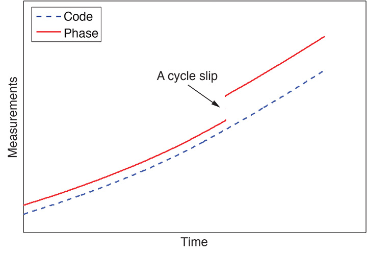
    A cycle slip causes a jump in carrier-phase measurements when the receiver phase tracking loops experience a temporary loss of lock due to signal blockage or some other disturbing factor. On the other hand, pseudoranges remain unaffected. This is graphically depicted in FIGURE 1. When a cycle slip happens, the Doppler (cycle) counter in the receiver restarts, causing a jump in the instantaneous accumulated phase by an integer number of cycles. Thus, the integer counter is reinitialized, meaning that ambiguities are unknown again, producing a sudden change in the carrier-phase observations.

    FIGURE 1. A cycle slip affecting phase measurements but not the pseudoranges.
    FIGURE 1. A cycle slip affecting phase measurements but not the pseudoranges.

    Once a cycle slip is detected, it can be handled in two ways. One way is to repair the slip. The other way is to reinitialize the unknown ambiguity parameter in the phase measurements. The former technique requires an exact estimation of the size of the slip but could be done instantaneously. The latter solution is more secure, but it is time-consuming and computationally intensive. In our work, we follow the first approach, providing a real-time cycle-slip detection and correction algorithm based on a GPS/inertial integration scheme.

    GPS/INS Integration

    An inertial navigation system (INS) can provide a smoother and more continuous navigation solution at higher data rates than a GPS-only system, since it is autonomous and immune to the kinds of interference that can deteriorate GPS positioning quality. However, INS errors grow with time due to the inherent mathematical double integration in the mechanization process. Thus, both GPS and INS systems exhibit mutually complementary characteristics, and their integration provides a more accurate and robust navigation solution than either stand-alone system. GPS/INS integration is often implemented using a filtering technique. A Kalman filter is typically selected for its estimation optimality and time-recursion properties.

    The two major approaches of GPS/INS integration are loosely coupled and tightly coupled. The former strategy is simpler and easier to implement because the inertial and GPS navigation solutions are generated independently before being weighted together by the Kalman filter. There are two main drawbacks with this approach: 1) signals from at least four satellites are needed for a navigation solution, which cannot always be guaranteed; and 2) the outputs of the GPS Kalman filter are time correlated, which has a negative impact upon the system performance. The latter strategy performs the INS/GPS integration in a single centralized Kalman filter. This architecture eliminates the problem of correlated measurements, which arises due to the cascaded Kalman filtering in the loosely coupled approach. Moreover, the restriction of visibility of at least four satellites is removed. We specifically use a tightly coupled GPS/reduced inertial sensor system approach.

    Reduced Inertial Sensor System. Recently, microelectromechanical system or MEMS-grade inertial sensors have been introduced for low-cost navigation applications. However, these inexpensive sensors have complex error characteristics.

    Therefore, current research is directed towards the utilization of fewer numbers of inertial sensors inside the inertial measurement unit (IMU) to obtain the navigation solution.

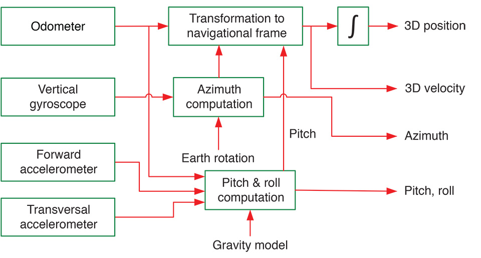
    The advantage of this trend is twofold. The first is avoidance of the effect of inertial sensor errors. The second is reduction of the cost of the IMU in general. One such minimization approach, and the one used in our work, is known as the reduced inertial sensor system (RISS). The RISS configuration uses one gyroscope, two accelerometers, and a vehicle wheel-rotation sensor. The gyroscope is used to observe the changes in the vehicle’s orientation in the horizontal plane. The two accelerometers are used to obtain the pitch and roll angles. The wheel-rotation sensor readings provide the vehicle’s speed in the forward direction. FIGURE 2 shows a general view of the RISS configuration.

    FIGURE 2. A general view of the RISS configuration.
    FIGURE 2. A general view of the RISS configuration.

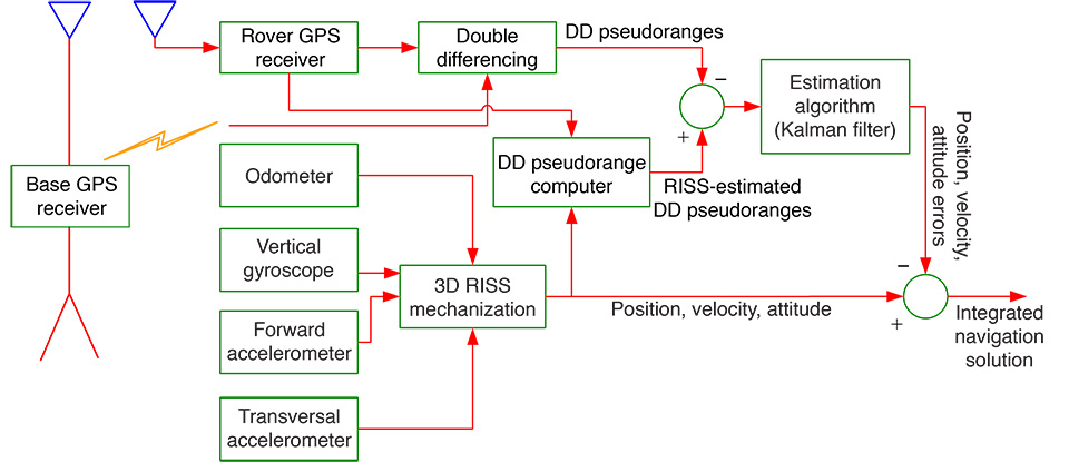
    A block diagram of the tightly coupled GPS/RISS used in our work is shown in FIGURE 3. At this stage, the system uses GPS pseudoranges together with the RISS observables to compute an integrated navigation solution. In this three-dimensional (3D) version of RISS, the system has a total of nine states. These states are the latitude, longitude, and altitude errors ( Inn-E1; the east, north, and up velocity errors Inn-E2  ; the azimuth error Inn-E3 ; the error associated with odometer-driven acceleration Inn-E4 ; and the gyroscope error  Inn-E5.

    The nine-state error vector xk at time tk is expressed as:
    Inn-E6    (1)

    FIGURE 3. Tightly coupled integration of GPS/RISS using differential pseudorange measurements.
    FIGURE 3. Tightly coupled integration of GPS/RISS using differential pseudorange measurements.

    Cycle Slip Detection and Correction

    Cycle slip handling usually happens in two discrete steps: detection and fixing or correction. In the first step, using some testing quantity, the location (or time) of the slip is found. During the second step, the size of the slip is determined, which is needed along with its location to fix the cycle slip. Various techniques have been introduced by researchers to address the problem of cycle-slip detection and correction. Different measurements and their combinations are used including carrier phase minus code (using L1 or L2 measurements), carrier phase on L1 minus carrier phase on L2, Doppler (on L1 or L2), and time-differenced phases (using L1 or L2). In GPS/INS integration systems, the INS is used to predict the required variable to test for a cycle slip, which is usually the true receiver-to-satellite range in double-difference (DD) mode, differencing measurements between a reference receiver and the roving receiver and between satellites. In this article, we introduce a tightly coupled GPS/RISS approach for cycle-slip detection and correction, principally for land vehicle navigation using a relative-positioning technique.

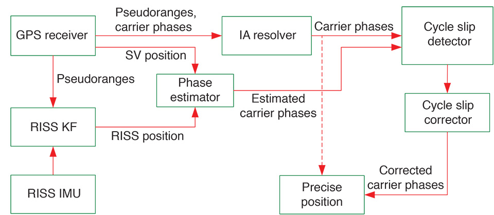
    Principle of the Algorithm. The proposed algorithm compares DD L1 carrier-phase measurements with estimated values derived from the output of the GPS/RISS system. In the case of a cycle slip, the measurements are corrected with the calculated difference. A general overview of the system is given in FIGURE 4.

    FIGURE 4. The general flow diagram of the proposed algorithm.
    FIGURE 4. The general flow diagram of the proposed algorithm.

    The number of slipped cycles Inn-E7 is given by
    Inn-E8   (2)
    where
    Inn-E9is the DD carrier-phase measurement (in cycles)
    Inn-10is DD estimated carrier phase value (in cycles).
    Inn-11is compared to a pre-defined threshold μ . If the threshold is exceeded, it indicates that there is a cycle slip in the DD carrier-phase measurements.

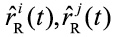
    Theoretically, Inn-E7  would be an integer but because of the errors in the measured carrier phase as well as errors in the estimations coming from the INS system, Inn-E7 will be a real or floating-point number.

    The estimated carrier-phase term in Equation (2) is obtained as follows:
    Inn-12    (3)
    where
    λ is the wavelength of the signal carrier (in meters)
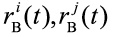
    Inn-13are the estimated ranges from the rover to satellites i and j respectively (in meters)
    Inn-14are known ranges from the base to satellites i and j respectively (in meters).
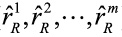
    What we need to get from the integrated GPS/RISS system is the estimated range vector from the receiver to each available satellite ( Inn-15). Knowing our best position estimate, we can calculate ranges from the receiver to all available satellites through:
    Inn-16(4)
    where
    Inn-17 is the calculated range from the receiver to the mth satellite
    xKF is the receiver position obtained from GPS/RISS Kalman filter solution
    xm is the position of the mth satellite
    M is the number of available satellites.
    Then, the estimated DD carrier-phase term in Equation (3) can be calculated and the following test quantity in Equation (2) can be applied:
    Inn-18   (5)
    If a cycle slip occurred in the ith DD carrier-phase set, the corresponding set is instantly corrected for that slip by:
    Inn-19   (6)
    where s is the DD carrier-phase-set number in which the cycle slip has occurred.

    Experimental Work

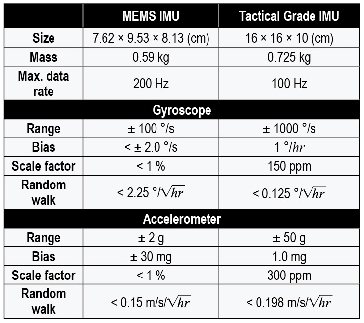
    The performance of the proposed algorithm was examined on the data collected from several real land-vehicle trajectories. A high-end tactical grade IMU was integrated with a survey-grade GPS receiver to provide the reference solution. This IMU uses three ring-laser gyroscopes and three accelerometers mounted orthogonally to measure angular rate and linear acceleration. The GPS receiver and the IMU were integrated in a commercial package. For the GPS/RISS solution, the same GPS receiver and a MEMS-grade IMU were used. This IMU is a six-degree of freedom inertial system, but data from only the vertical gyroscope, the forward accelerometer, and the transversal accelerometer was used. TABLE 1 gives the main characteristics of both IMUs. The odometer data was collected using a commercial data logger through an On-Board Diagnostics version II (OBD-II) interface. Another GPS receiver of the same type was used for the base station measurements. The GPS data was logged at 1 Hz.

    Table 1. Characteristics of the MEMS and tactical grade IMUs.
    Table 1. Characteristics of the MEMS and tactical grade IMUs.

    Several road trajectories were driven using the above-described configuration. We have selected one of the trajectories, which covers several real-life scenarios encountered in a typical road journey, to show the performance of the proposed algorithm. The test was carried out in the city of Kingston, Ontario, Canada. The starting and end point of the trajectory was near a well-surveyed point at Fort Henry National Historic Site where the base station receiver was located. The length of the trajectory was about 30 minutes, and the total distance traveled was about 33 kilometers with a maximum baseline length of about 15 kilometers. The trajectory incorporated a portion of Highway 401 with a maximum speed limit of 100 kilometers per hour and suburban areas with a maximum speed limit of 80 kilometers per hour. It also included different scenarios including sharp turns, high speeds, and slopes.

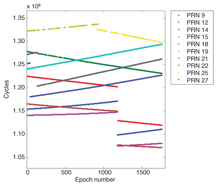
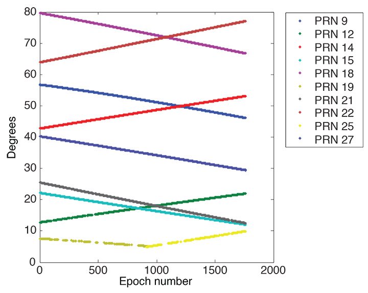
    FIGURE 5 shows measured carrier phases at the rover for the different satellites. Some satellites show very poor presence whereas some others are consistently available. Satellites elevation angles can be seen in FIGURE 6.

    FIGURE 5. Measured carrier phase at the rover.
    FIGURE 5. Measured carrier phase at the rover.
    FIGURE 6. Satellite elevation angles.
    FIGURE 6. Satellite elevation angles.

    Results

    We start by showing some results of carrier-phase estimation errors. Processing is done on what is considered to be a cycle-slip-free portion of the data set for some persistent satellites (usually with moderate to high elevation angles). Then we show results for the cycle-slip-detection process by artificially introducing cycle slips in different scenarios. In the ensuing discussion (including tables and figures), we show results indicating satellite numbers without any mention of reference satellites, which should be implicit as we are dealing with DD data.
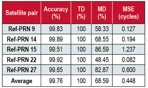
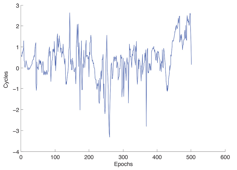
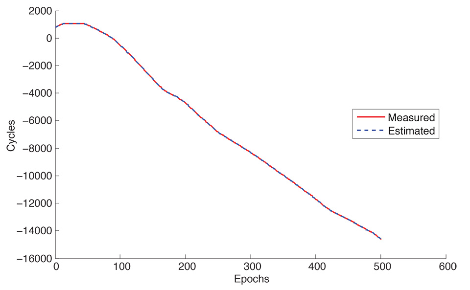
    FIGURE 7 shows DD carrier-phase estimation errors whereas FIGURE 8 shows DD measured carrier phases versus DD estimated carrier phases for sample satellite PRN 22.

    FIGURE 7. DD-carrier-phase estimation error, reference satellite with PRN 22.
    FIGURE 7. DD-carrier-phase estimation error, reference satellite with PRN 22.
    FIGURE 8. Measured versus estimated DD carrier phase, reference satellite with PRN 22.
    FIGURE 8. Measured versus estimated DD carrier phase, reference satellite with PRN 22.

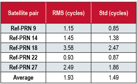
    As can be seen in TABLE 2, the root-mean-square (RMS) error varies from 0.93 to 3.58 cycles with standard deviations from 0.85 to 2.47 cycles. Estimated phases are approximately identical to the measured ones. Nevertheless, most of the DD carrier-phase estimates have bias and general drift trends, which need some elaboration. In fact, the bias error can be the result of more than one cause. The low-cost inertial sensors always have bias in their characteristics, which plays a major role in this. The drift is further affecting relatively lower elevation  angle satellites which can also be attributed to more than one reason. Indeed, one reason for choosing this specific trajectory, which was conducted in 2011, was to test the algorithm with severe ionospheric conditions as the year 2011 was close to a solar maximum: a period of peak solar activity in the approximately 11-year sunspot cycle.

    Table 2. Estimation error for DD carrier phases (in cycles).
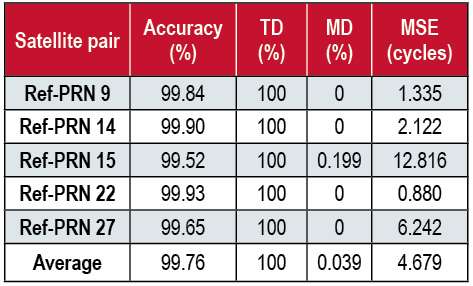
    Table 2. Estimation error for DD carrier phases (in cycles).
    Moreover, the time of the test was in the afternoon, which has the maximum ionospheric effects during the day. Thus, most part of the drift trend must be coming from ionospheric effects as the rover is moving away from the base receiver during this portion of the trajectory. Furthermore, satellite geometry could contribute to this error component. Most of the sudden jumps coincide with, or follow, sharp vehicle turns and rapid tilts. Table 2 shows the averaged RMS and standard deviation (std) DD carrier-phase estimation error for the sample satellite-pairs. We introduced cycle slips at different rates or intensities and different sizes to simulate real-life scenarios. Fortunately, cycle slips are usually big as mentioned earlier and this was corroborated by our observations from real trajectory data. Therefore, it is more important to detect and correct for bigger slips in general.

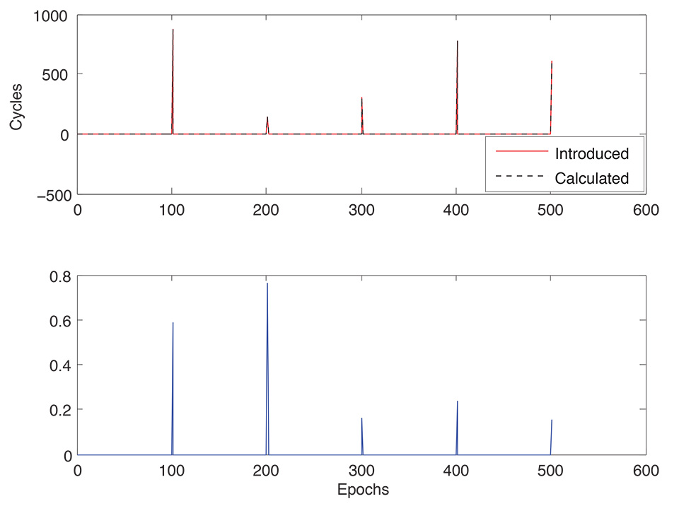
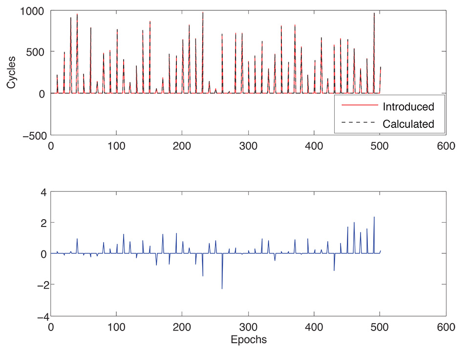
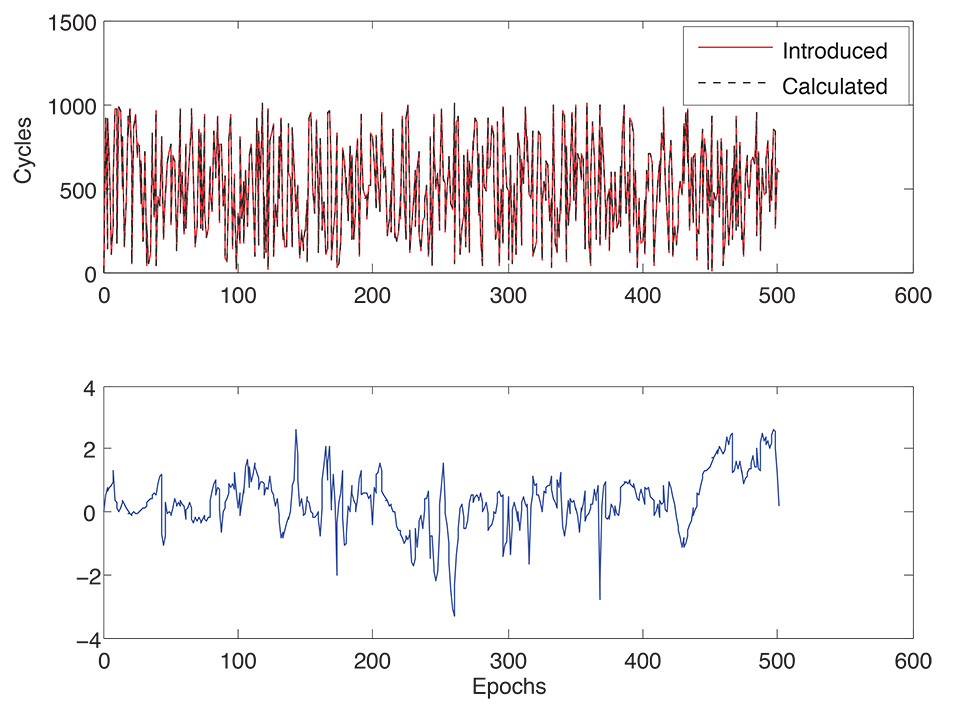
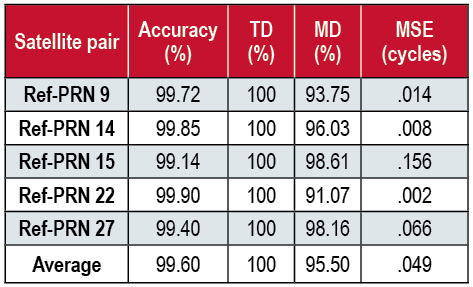
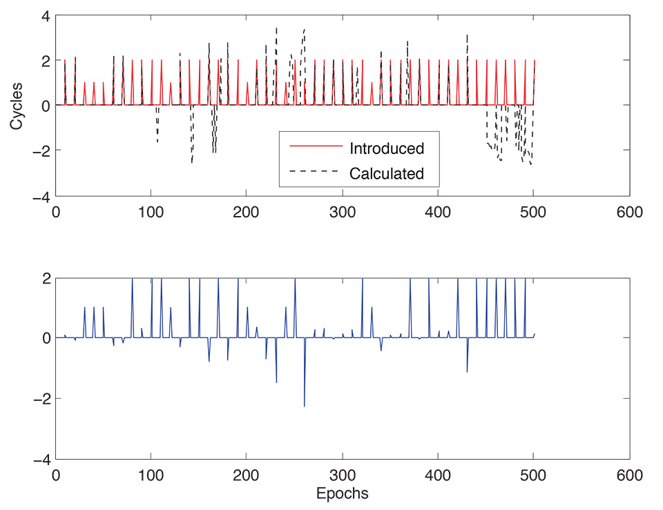
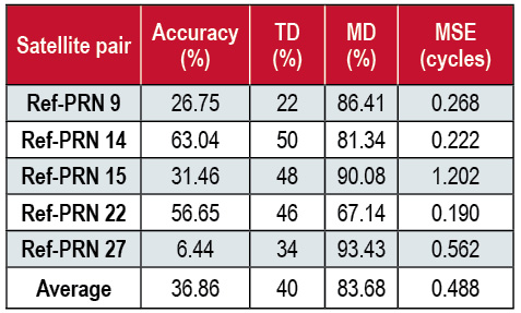
    Introducing and Detecting Cycle Slips. To test the robustness of the algorithm, we started with an adequate cycle slip size. Cycle slips of size 10–1000 cycles were introduced with different intensities. These intensities are categorized as few (1 slip per 100 epochs), moderate (10 slips per 100 epochs), and severe (100 slips per 100 epochs). This was applied for all DD carrier-phase measurement sets simultaneously. The threshold was set to 1.9267 (average of RMS error for all satellite-pairs) cycles. Four metrics were used to describe the results. Mean square error (MSE); accuracy, the detected cycle slip size with respect to the introduced size; True detection (TD) ratio; and Mis-detection (MD) ratio. Due to space constraints and the similarity between results for different satellites, we only show results for the reference satellite with PRN 22. FIGURES 9–12 show introduced versus calculated cycle slips along with the corresponding detection error for sample satellites in the different scenarios. TABLES 3–5 summarize these results.

    FIGURE 9. Introduced and calculated cycle slips (upper plot) and detection error (lower plot). Few cycle slips case, reference satellite with PRN 22.
    FIGURE 9. Introduced and calculated cycle slips (upper plot) and detection error (lower plot). Few cycle slips case, reference satellite with PRN 22.
    FIGURE 10. Introduced and calculated cycle slips (upper plot) and detection error (lower plot). Moderate cycle slips case, reference satellite with PRN 22.
    FIGURE 10. Introduced and calculated cycle slips (upper plot) and detection error (lower plot). Moderate cycle slips case, reference satellite with PRN 22.
    FIGURE 11. Introduced and calculated cycle slips (upper plot) and detection error (lower plot). Intensive cycle slips case, reference satellite with PRN 22.
    FIGURE 11. Introduced and calculated cycle slips (upper plot) and detection error (lower plot). Intensive cycle slips case, reference satellite with PRN 22.
    FIGURE 12. Introduced and calculated cycle slips (upper plot) and detection error (lower plot). Small cycle slips case, reference satellite with PRN 22.
    FIGURE 12. Introduced and calculated cycle slips (upper plot) and detection error (lower plot). Small cycle slips case, reference satellite with PRN 22.
    Table 3. Few slips (1 slip per 100 epochs).
    Table 3. Few slips (1 slip per 100 epochs).
    Table 4. Moderate slips (10 slips per 100 epochs).
    Table 4. Moderate slips (10 slips per 100 epochs).
    Table 5. Intensive slips (100 slips per 100 epochs).
    Table 5. Intensive slips (100 slips per 100 epochs).

    All introduced cycle slips were successfully detected in all of the few, moderate, and severe cases with very high accuracy. A slight change in the accuracy (increasing with higher intensity) among the different scenarios shows that detection accuracy is not affected by cycle-slip intensity. Higher mis-detection ratios for smaller cycle-slip intensity comes from bigger error margins than the threshold for several satellite pairs. However, this is not affecting the overall accuracy strongly as all mis-detected slips are of comparably very small sizes. MD ratio is zero in the intensive cycle-slip case as all epochs contain slips is an indicator of performance compromise with slip intensity.

    It is less likely to have very small cycle slips (such as 1 to 2 cycles) in the data and usually it will be hidden with the higher noise levels in kinematic navigation with low-cost equipment. However, we wanted to show the accuracy of detection in this case. We chose the moderate cycle slip intensity for this test. TABLE 6 summarizes results for all satellites.

    Table 6. Small slips (1–2 cycles) at moderate intensity (10 slips per 100 epochs).
    Table 6. Small slips (1–2 cycles) at moderate intensity (10 slips per 100 epochs).

    We get a moderate detection ratio and modest accuracy as the slips are of sizes close to the threshold. The MSE values are not far away from the case of big cycle slips but with higher mis-detection ratio.

    Conclusions

    The performance of the proposed algorithm was examined on several real-life land vehicle trajectories, which included various driving scenarios including high and slow speeds, sudden accelerations, sharp turns and steep slopes. The road testing was designed to demonstrate the effectiveness of the proposed algorithm in different scenarios such as intensive and variable-sized cycle slips.

    Results of testing the proposed method showed competitive detection rates and accuracies comparable to existing algorithms that use full MEMS IMUs. Thus with a lower cost GPS/RISS integrated system, we were able to obtain a reliable phase-measurement-based navigation solution. Although the testing discussed in this article involved post-processing of the actual collected data at the reference station and the rover, the procedure has been designed to work in real time where the measurements made at the reference station are transmitted to the rover via a radio link. This research has a direct influence on navigation in real-time applications where frequent cycle slips occur and resolving integer ambiguities is not affordable because of time and computational reasons and where system cost is an important factor.

    Acknowledgments

    This article is based on the paper “Real-time Cycle-slip Detection and Correction for Land Vehicle Navigation using Inertial Aiding” presented at ION GNSS+ 2013, the 26th International Technical Meeting of the Satellite Division of The Institute of Navigation held in Nashville, Tennessee, September 16–20, 2013.

    Manufacturers

    The research reported in this article used a Honeywell Aerospace HG1700 AG11 tactical-grade IMU and a NovAtel OEM4 GPS receiver integrated in a NovAtel G2 Pro-Pack SPAN unit, a Crossbow Technology (now Moog Crossbow) IMU300CC MEMS-grade IMU, an additional NovAtel OEM4 receiver at the base station, a pair of NovAtel GPS-702L antennas, and a Davis Instruments CarChip E/X 8225 OBD-II data logger.


    Malek Karaim is a Ph.D. student in the Department of Electrical and Computer Engineering of Queen’s University, Kingston, Ontario, Canada.

    Tashfeen Karamat is a doctoral candidate in the Department of Electrical and Computer Engineering at Queen’s University.

    Aboelmagd Noureldin is a cross-appointment professor in the Departments of Electrical and Computer Engineering at both Queen’s University and the Royal Military College (RMC) of Canada, also in Kingston.

    Mohamed Tamazin is a Ph.D. student in the Department of Electrical and Computer Engineering at Queen’s University and a member of the Queen’s/RMC NavINST Laboratory.

    Mohamed M. Atia is a research associate and deputy director of the Queen’s/RMC NavINST Laboratory. 


    FURTHER READING

    • Cycle Slips

    “Instantaneous Cycle-Slip Correction for Real-Time PPP Applications” by S. Banville and R.B. Langley in Navigation, Vol. 57, No. 4, Winter 2010–2011, pp. 325–334.

    “GPS Cycle Slip Detection and Correction Based on High Order Difference and Lagrange Interpolation” by H. Hu and L. Fang in Proceedings of PEITS 2009, the 2nd International Conference on Power Electronics and Intelligent Transportation System, Shenzhen, China, December 19–20, 2009, Vol. 1, pp. 384–387, doi: 10.1109/PEITS.2009.5406991.

    “Cycle Slip Detection and Fixing by MEMS-IMU/GPS Integration for Mobile Environment RTK-GPS” by T. Takasu and A. Yasuda in Proceedings of ION GNSS 2008, the 21st International Technical Meeting of the Satellite Division of The Institute of Navigation, Savannah, Georgia, September 16–19, 2008, pp. 64–71.

    Instantaneous Real-time Cycle-slip Correction of Dual-frequency GPS Data” by D. Kim and R. Langley in Proceedings of KIS 2001, the International Symposium on Kinematic Systems in Geodesy, Geomatics and Navigation, Banff, Alberta, June 5–8, 2001, pp. 255–264.

    Carrier-Phase Cycle Slips: A New Approach to an Old Problem” by S.B. Bisnath, D. Kim, and R.B. Langley in GPS World, Vol. 12, No. 5, May 2001, pp. 46-51.

    “Cycle-Slip Detection and Repair in Integrated Navigation Systems” by A. Lipp and X. Gu in Proceedings of PLANS 1994, the IEEE Position Location and Navigation Symposium, Las Vegas, Nevada, April 11–15, 1994, pp. 681–688, doi: 10.1109/PLANS.1994.303377.

    Short-Arc Orbit Improvement for GPS Satellites by D. Parrot, M.Sc.E. thesis, Department of Geodesy and Geomatics Engineering Technical Report No. 143, University of New Brunswick, Fredericton, New Brunswick, Canada, June 1989.

    • Reduced Inertial Sensor Systems

    “A Tightly-Coupled Reduced Multi-Sensor System for Urban Navigation” by T. Karamat, J. Georgy, U. Iqbal, and N. Aboelmagd in Proceedings of ION GNSS 2009, the 22nd International Technical Meeting of the Satellite Division of The Institute of Navigation, Savannah, Georgia, September 22–25, 2009, pp. 582–592.

    “An Integrated Reduced Inertial Sensor System – RISS / GPS for Land Vehicle” by U. Iqbal, A. Okou, and N. Aboelmagd in Proceedings of PLANS 2008, the IEEE/ION Position Location and Navigation Symposium, Monterey, California, May 5–8, 2008, pp. 1014–1021, doi: 10.1109/PLANS.2008.4570075.

    • Integrating GPS and Inertial Systems

    Fundamentals of Inertial Navigation, Satellite-based Positioning and their Integration by N. Aboelmagd, T. B. Karmat, and J. Georgy. Published by Springer-Verlag, New York, New York, 2013.

    Aided Navigation: GPS with High Rate Sensors by J. A. Farrell. Published by McGraw-Hill, New York, New York, 2008.

    Global Positioning Systems, Inertial Navigation, and Integration, 2nd edition, by M.S. Grewal, L.R. Weill, and A.P. Andrews. Published by John Wiley & Sons, Inc., Hoboken, New Jersey, 2007.

  • The System: Two More Threes for Space

    Artist's concept of a GPS III satellite in orbit, courtesy of Lockheed Martin.
    Artist’s concept of a GPS III satellite in orbit, courtesy of Lockheed Martin.

    Air Force Orders GPS III Satellites 05 and 06 from Lockheed Martin

    A December 12 contract modification provided Air Force funding to Lockheed Martin to complete the fifth and sixth GPS III space vehicles (SV 05-06).  Lockheeed originally received funding to procure long-lead parts for satellites five through eight (SV 05-08) in February 2013.

    The $200,700,415 cost-plus-incentive-fee modification (P00276) on an existing contract (FA8807-08-C-0010) for GPS III space vehicles 05 and 06 means that work will be performed at Littleton. Colorado and Clifton, New Jersey, and is expected to be completed by Dec. 14, 2017 for space vehicle 05 and June 14, 2018 for space vehicle 06.  The Air Force Space and Missile Systems Center Contracting Directorate, Los Angeles Air Force Base, California, is the contracting activity.

    Galileo Achieves First Airborne Tracking

    The European Space Agency’s Galileo satellites have achieved their first aerial fix of longitude, latitude, and altitude, enabling the inflight tracking of a test aircraft.

    ESA’s four Galileo satellites in orbit have supported months of positioning tests on the ground across Europe since the first fix in March. Now the first aerial tracking using Galileo has taken place, determining the position of an aircraft using only its own independent navigation system.

    The milestone took place on a Fairchild Metro-II above Gilze-Rijen Air Force Base in the Netherlands on November 12. It was part of an aerial campaign overseen jointly by ESA and the National Aerospace Laboratory of the Netherlands, NLR, with the support of Eurocontrol, the European Organisation for the Safety of Air Navigation, and LVNL, the Dutch Air Navigation Service Provider.

    A pair of Galileo test receivers was used aboard the aircraft, the same kind employed for Galileo testing in the field and in labs across Europe. They were connected to an aeronautical-certified triple-frequency Galileo-ready antenna mounted on top of the aircraft.

    Tests were scheduled during periods when all four Galileo satellites were visible in the sky. The receivers fixed the plane’s position, as well as determining key variables such as the position, velocity, and timing accuracy; time to first fix; signal-to-noise ratio; range error; and range–rate error.

    Testing covered both Galileo’s publicly available Open Service and the more precise, encrypted Public Regulated Service, whose availability is limited to governmental entities.

    Flights covered all major phases: take off, straight and level flight with constant speed, orbit, straight and level flight with alternating speeds, turns with a maximum bank angle of 60 degrees, pull-ups and push-overs, approaches and landings.

    The flights also allowed positioning to be carried out during a wide variety of conditions, such as vibrations, speeds up to 456 km/h, accelerations up to 2 ghorizontal and 0.5–1.5 gvertical, and rapid jerks. The maximum altitude reached during the flights was 3,000 meters.

    GPS III Prototype Proves Constellation Compatibility

    The Lockheed Martin prototype of the next-generation GPS satellite, the GPS III, has proven that it is backwardly compatible with the existing GPS satellite constellation in orbit.

    During tests concluded on October 17, Lockheed Martin’s GPS III testbed successfully communicated via cross-links to Air Force simulators of the current GPS constellation in orbit. The current GPS constellation includes GPS IIR, GPS IIR-M, and GPS IIF satellites.

    Testing also demonstrated the ability of an Air Force receiver to track navigation signals transmitted by the GPS III Nonflight Satellite Testbed (GNST). The GNST is a full-sized, functional satellite prototype at Cape Canaveral Air Force Station.

    “These tests represent the first time when the GNST’s flight-like hardware has communicated with flight-like hardware from the rest of the GPS constellation and with a navigation receiver,” explained Paul Miller, Lockheed Martin’s director for GPS III Development. “This provides early confidence in the GPS III’s design to bring advanced capabilities to our nation, while also being backward-compatible.”

    The first flight-ready GPS III satellite is expected to arrive at Cape Canaveral in 2014, for launch by the Air Force in 2015.
    GPS III satellites will be the first GPS space vehicles with a new L1C civil signal designed to make it interoperable with other international global navigation satellite systems.

    The GNST has helped to identify and resolve development issues prior to integration and test of the first GPS III flight space vehicle (SV 01). It has gone through the development, test, and production process for the GPS III program first, significantly reducing risk for the flight vehicles, improving production predictability, increasing mission assurance, and lowering overall program costs.

    The GPS III team is led by the Global Positioning Systems Directorate at the U.S. Air Force Space and Missile Systems Center.

    Lockheed Martin is the GPS III prime contractor, with teammates including ITT Exelis, General Dynamics, Infinity Systems Engineering, Honeywell, ATK, and other subcontractors.

    Good News for Users and Manufacturers

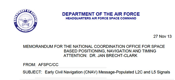
    The U.S. Air Force is directing transmission of continuous CNAV message-populated L2C and L5 signals starting in April 2014. The move is designed to help development of user equipment compatible with the civil signals. Full text of the CNAV memo appears below.

    CNAV-header

    Galileo FOC Satellites Endure Simulated Space Tests

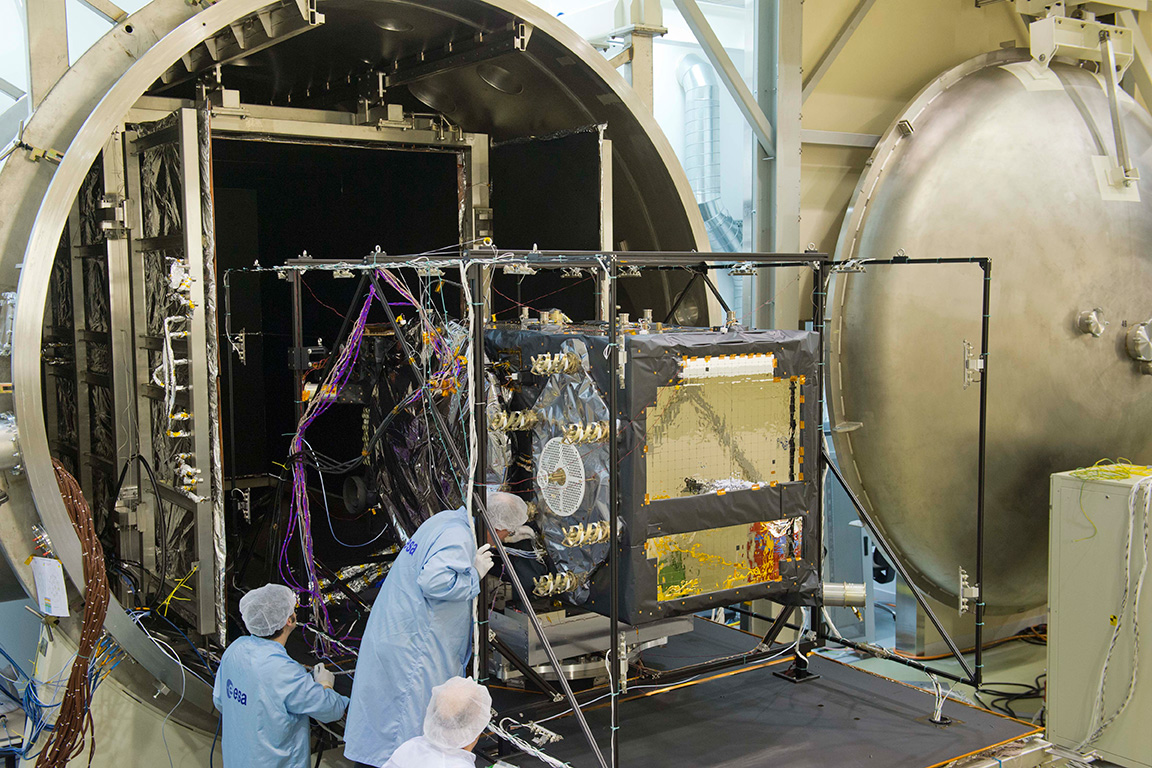
    The European Space Agency’s newest Galileo satellite has emerged from five weeks of simulated space conditions. On November 29, a hatch slid open to end its thermal-vacuum test, a milestone on the way to orbit.

    The satellite was placed in the 4.5-meter-diameter Phenix chamber in ESA’s ESTEC Test Centre in Noordwijk, the Netherlands, in late October. Once inside, the air was pumped out to create a space-quality vacuum. Temperature extremes were also reproduced, with the six copper walls of the thermal tent cooled by liquid nitrogen down to –180°C.

    A second Galileo vehicle has  been undergoing the same rigors at the site, along with a vibration and shock test to reproduce separation from the launcher. Thermal-vacuum testing on the second model will begin in early 2014. The two satellites will be launched on a Soyuz rocket from Europe’s Spaceport in French Guiana in mid-2014.

    The next satellite is expected to arrive at ESTEC in March, with further satellites following every seven weeks or so. A total of 22 FOC satellites are being built by OHB in Germany, with navigation payloads being delivered from Surrey Satellite Technology Ltd. in the UK.

    The first Galileo Full Operational Capability satellite emerges from the Phenix test chamber after five weeks of thermal–vacuum testing.
    The first Galileo Full Operational Capability satellite emerges from the Phenix test chamber after five weeks of thermal–vacuum testing.
  • Data Sources for BeiDou, Real-Time Ephemeris

    From the GNSS R&D Discussion Group on LinkedIn

    Hello, everyone, I am looking for a tool/software which can generate a satellite geometry distribution map of Chinese BeiDou over Asia. Just like a GPS PDOP global map. Could anyone give me a help? Thanks a lot in advance.

    Comments

    Maybe this tool helps you: AVIGA Service Volume Simulator: www.navpos.de/Publications/AVIGA_Pro_Flyer.pdf


    We use this tool to plot satellite coverage: www.agi.com/


    We have a standard mission planning tool that can do it (GPS, GLONASS, Galileo and BeiDou) and is included with our post-processing software, called EZSurv. If you’re interested to try the planner, I can send an evaluation copy of it.


    You can use the (free!) Trimble online Planner (www.trimble.com/GNSSPlanningOnline/#/SatLibrary). Supports GPS, GLONASS, Galileo, BeiDou, QZSS. There was an offline tool available, too, but can’t find it anymore. Really helpful tools, thanks Trimble!


    We at GMV have our own Service Volume Simulator, named polaris (www.gmv.com/en/space/Polaris/). polaris has been (and is being) extensively used in the Galileo and EGNOS programmes.

    From the CANSPACE Discussion Group (ListServ)

    I’d like to view broadcast SV health data that is accurate to the minute. When I use IGS stations, I can only find health data in nav files to the resolution of two hours. Could someone point me to where I could find SV health data with the granularity of 1 minute or better?

    Comments

    Some IGS stations stream data, including ephemerides, in real time. Presumably, any change in SV health would be reflected in an updated ephemeris. Real-time ephemeris data from the global network is provided on available Ntrip streams. Georg Weber (the scientific director in the Department of Geodesy at the German Federal Agency for Cartography and Geodesy (BKG) and a member of the IGS Real-time Working Group and the Radio Technical Commission for Maritime (RTCM) Services Special Committee (SC) 104 on Differential Global Navigation Satellite Systems (DGNSS)) kindly supplied this information:

    “If I understand things correctly, then an updated navigation message is disseminated immediately when GPS operators become aware of a problem and that this is the only real-time source of information regarding SV health coming directly from the system. Hence real-time access to RTCM broadcast ephemeris messages is what you are asking for. Here is how to get it:


    The Navigation message is only updated every two hours (currently) so the granularity you require is not possible, as the health flag is an official designation from the GPS control center.  The fastest changing navigation files are in the IGS Data centers called “hourDDD0.13n” for example, for today here: ftp://cddis.nasa.gov/gps/data/hourly/2013/318/hour3180.13n.Z

    This file gets updated hourly (or more) with the contributions from the navigation files of the IGS network.
    A faster way of noting changes would be to monitor several worldwide data real-time streams from public stations using the BNC software to monitor the health flags, but while the data will come in real-time the changes in flag status only take place every two hours, but at least you will see a health flag change very quickly. Check out:

    http://www.igs-ip.net/home

    http://igs.bkg.bund.de/ntrip/download

    I hope that is helpful.

  • Out in Front: A Glow under the Snow

    Out in Front: A Glow under the Snow

    Prague is now the headquarters of the European GNSS Agency (GSA).
    Prague is now the headquarters of the European GNSS Agency (GSA).

    A holiday card from a colleague in Europe calls to mind GNSS’s headlong course into the future, coupled with that most backward-reflective of human preoccupations, history.

    The European GNSS Agency (GSA), whence originated this card, moved from Brussels to Prague in September 2012, in a nod to the pan-European nature of the European Union (EU) generally and its GNSSs, Galileo and EGNOS, in particular. No EU agency headquarters had been sited in Eastern Europe, and it was deemed that some soon must do. Prague made a strong bid for the GSA.

    A political, cultural, and economic center of central Europe under its current name since the year 908, it has a settlement history dating back to 1306 BC. Good King Wenceslaus, who looked out upon the snow round about, deep and crisp and even, and about whom we sang festively this past season, ruled from Prague around 935, subsequently rose to sainthood, and is the patron saint of Bohemia, the Czech homeland.

    The GSA has a rather variegated mission: it “manages public interests related to European GNSS programmes.” This includes everything from marketing to security — in a sense, everything satnav-related that scientists and engineers do not do. Its list of tasks and responsibilities includes 12 subheads and 61 bulleted points.

    Carlo des Dorides, GSA executive director, noted upon opening the new headquarters in 2012 that Prague derives from the Slavic word praga, for threshold. “I think this is appropriate for the GSA and Galileo, as it represents the beginning of a key step for both.” EC vice-president Antonio Tajani added, “Galileo is important not only for space policy and science, but for the services and jobs that it brings.”

    Thus the many GSA staffers labor to wring full advantage for modern economies from the space-based radio signal generators, amid the cobblestone streets and ancient monuments of one of the best-preserved ancient European cities, a UNESCO Cultural Heritage site.

    While busily plunging into the future, we cannot escape our past.

  • Raytheon Granted $8.5M Change Order for OCX M-Code Implementation

    Raytheon Intelligence and Information Systems has been awarded a change order for work that costs up to $8.5 million on its existing contract to ensure that the new military signal, M-code, works with the GPS Operational Control System, according to an announcement from the Pentagon as reported by Space News.

    Raytheon is building the ground station (OCX) for a new generation of satellites that will bring more safety and precision to GPS. The contract modification is to assure implementation of M-code capabilities across OCX Block 1 and 2. M-code is the new highly secure, anti-jam signal designed for the GPS III constellation. The current GPS ground control system lacks M-code capability.

    The OCX is designed to work with the advanced GPS III positioning, navigation and timing satellites, slated to start launching in 2015, and also will be backwardly compatible with existing GPS satellites.

    Raytheon won the $886.4 million prime contract to develop the OCX in February 2010. Work will be performed at Raytheon’s facility in Aurora, Colorado, and is expected to be completed by August 31, 2016.

    The Air Force Space and Missile Systems Contracting Directorate, Los Angeles Air Force Base, California, is the contracting agency.

    Details on the contract change order: Raytheon Intelligence and Information Systems, Aurora, Colo., has been awarded an unpriced change order (P00112) with a not-to-exceed of $8,595,748 on an existing contract (FA8807-10-C-0001) for M-Code Implementation on the Operational Control System.  The contract modification is to assure implementation of M-Code Capabilities across OCX Block 1 and 2. Work will be performed at Aurora, Colo., and is expected to be completed by Aug. 31, 2016.  Fiscal 2014 research and development funds will be obligated at definitization.  The Air Force Space and Missile Systems Contracting Directorate, Los Angeles Air Force Base, Calif., is the contracting activity.

  • Part 2: Is It Legal to Fly Drones for Mapping in the United States?

    After I published last month’s Is It Legal to Fly Drones for Mapping in the United States? article, I received a bit of reader feedback and attended a small conference focused on UASs for mapping. I learned and experienced a few new thoughts about UASs for mapping in the United States, so I thought I’d share them in a second installment.

    In early December, I attended the UAS Precision Farming Forum, a local conference that was sponsored by Yamhill County (Oregon) and targeted at the agriculture market. Yamhill County covers 718 square miles (1,860 square kilometers) and contains a healthy number of agricultural and vineyard farms.

    The conference was filled to capacity with 120 attendees, a complete lineup of speakers, and even a couple of exhibitors — not bad for a county-hosted local conference. This, and other such conferences around the United States, speaks volumes about the intense interest in UASs for agricultural uses in the U.S. For instance, the Association of Unmanned Vehicle Systems International (AUVSI) hosts an annual conference that attracts more than 8,000 attendees.

    At the Yamhill conference, I was most interested in hearing what speakers, attendees and exhibitors were saying about the FAA rules on civilians flying UAVs. The FAA is pretty clear (at least when responding to me and others) about the rules for civilian use.

    First of all, the most prolific user of UASs for mapping in Oregon seems to be Oregon State University, who possess eight Certificates of Authorization (CoA) from the FAA (Federal Aviation Administration) to operate UASs for research purposes, according to Dr. Michael Wing, associate professor of Geomatics. Dr. Wing explained that applying for a CoA from the FAA is an intense process requiring a lot of detail.

    PROJECT SITE PLATFORM SENSOR PARTNERS
    Forest Canopy/Structure McDonald Forest Prioria Maveric EO n-Link
    Search and Rescue McDonald Forest Aerospace Vapor/VTOL EO/IR n-Link
    Xmas Tree Research OSU No. Willamette Mikrokopter VTOL EO OSU, n-Link
    Potato Research HAREC Lockheed/Procerus EO/IR Boeing, n-Link, USDA
    Potato Research HAREC Tetracam HawkEye EO/IR Boeing, n-Link, USDA
    Large Scale Potato Res. Boardman Lockheed/Procerus EO/IR Boeing, n-Link, USDA
    Large Scale Potato Res. Boardman Tetracam HawkEye EO/IR Boeing, n-Link, USDA
    Flight Research Olympia Tetracam HawkEye Boeing, n-Link

    Dr. Wing also presented the bill of materials (BOM) for one of the UASs they are using, a Zephyr II.

    RiteWing Zephyr II
    RiteWing Zephyr II – 54″ Wingspan

    Zephyr II components (per OSU):

    2.4GHz Tx/Rx radio $360
    4500mAh LiPo battery $30
    Airspeed sensor $25
    ArduPilot APM 2.5 $160
    Canon S100 $300
    RiteWing Zephyr II $325
    TTC Radio $86
    uBlox GPS module $76
    Voltage regulator $15
    Total: $1,377

    When I asked Dr. Wing about the CoA restrictions, he said the CoAs require him to have an FAA-licensed pilot on site for each mission.

    If you recall from last month’s article, the FAA was very clear in responding to my queries that civilian commercial operation of UASs in the U.S. are prohibited unless the operator possesses a CoA from the FAA. Furthermore, the FAA says that commercial operation of UASs in the U.S. airspace is not allowed. The FAA is working on rules to integrate commercial UAS operation into the U.S. NAS (National Airspace System). The local AUVSI president, in his keynote speech, essentially said the same thing.

    I went to the exhibition area because I wanted to talk to the exhibitors and understand who their target market was, since commercial operations of UASs are prohibited. Their answers were interesting. Their first answer was that “farmers can fly UAS as hobbyists.” Recall that hobbyists (or modelers as the FAA refers to them) can operate UASs up to 400 feet above ground level (AGL). I asked the FAA specifically about this. They say that any commercial usage of UASs is prohibited. For example, you can take the same UAS that you fly for fun, and you are permitted to fly it below 400 feet AGL. However, once you use the same UAS for commercial purposes (such as mapping your farm), you are violating the FAA rules.

    When I pushed the vendor about this, his next answer was “as long as the farmer only flies it above his or her farm, they are allowed.” While I can sort of understand the logic behind his first statement, this statement didn’t make sense to me. If he’s using it for a commercial purpose, what difference does it make if it is over his own property or not? The problem I have with the vendor’s attitude is that he has little risk. It’s not against the FAA rules to sell UASs for commercial purposes. FAA rules are only violated when someone uses a UAS for commercial purposes. The bottom line: caveat emptor (buyer beware). The FAA is likely not going to pursue the manufacturer or distributor of the UAS, only the operator (the farmer).

    But, is it really against FAA rules to operate commercial UASs in the U.S.? The vendor claimed that he asked the FAA, and said that you will get a different answer from the FAA depending on who you speak to. To some extent, I understand the confusion. Furthermore, when I asked the FAA to cite examples of litigation, enforcement actions, etc., I was told I would need to file a Freedom of Information Act request (FOIA), which I did about November 12. Beyond acknowledging my request, the FAA has sent nothing. I’m told from others that they have made similar requests (months ago) and have still not received the FOIA information. This certainly casts a cloud of doubt over the confidence the FAA has in its position.

    Has anyone actually tested the FAA’s position in court?

    Thanks to Twitter, I linked up with an attorney who is representing a UAS operator who is being sued by the FAA for flying a UAS for commercial purposes in the United States. Attorney Brendan M. Schulman says his client’s case is the first to test the FAA rules in court. Mr. Schulman says that the FAA has no basis on which to enforce the rules. He’s arguing that the “FAA’s position is based on policy statement and not an enforceable regulation.”

    Schulman’s client, Raphael Pirker, a Swiss citizen and resident, was assessed a $10,000 fine pursuant 49 U.S.C. §§46301(a)(1) and (d)(2) and 46301(a)(5). The FAA argues that Pirker:

    1. On or about October 17, 2011, you were the pilot in command of a Ritewing Zephyr powered glider aircraft in the vicinity of the University of Virginia (UVA), Charlottesville,

    2. The aircraft referenced above is an Unmanned Aircraft System (UAS).

    3. At all times relevant herein you did not possess a Federal Aviation Administration pilot certificate.

    4. The aircraft referenced above contained a camera mounted on the aircraft which sent real time video to you on the ground.

    5. You operated the flight referenced above for compensation.

    6. Specifically, you were being paid by Lewis Communications to supply aerial photographs and video of the UVA campus and medical center.

    7. You deliberately operated the above-described aircraft at extremely low altitudes over vehicles, buildings, people, streets, and structures.

    8. Specifically, you operated the above-described aircraft at altitudes of approximately 10 feet to approximately 400 feet over the University of Virginia in a careless or reckless manner so as to endanger the life or property of another.

    9. For example, you deliberately operated the above-described aircraft in the following manner:

    a. You operated the aircraft directly towards an individual standing on a UVA sidewalk causing the individual to take immediate evasive maneuvers so as to avoid being struck by your aircraft.
    b. You operated the aircraft through a UVA tunnel containing moving vehicles.
    c. You operated the aircraft under a crane.
    d. You operated the aircraft below tree top level over a tree lined walkway.
    e. You operated the aircraft within approximately 15 feet of a UVA statue.
    f. You operated the aircraft within approximately 50 feet of railway tracks.
    g. You operated the aircraft within approximately 50 feet of numerous individuals.
    h. You operated the aircraft within approximately 20 feet of a UVA active street containing numerous pedestrians and cars.
    i. You operated the aircraft within approximately 25 feet of numerous UVA buildings.
    j. You operated the aircraft on at least three occasions under an elevated pedestrian walkway and above an active street.
    k. You operated the aircraft directly towards a two story UVA building below rooftop level and made an abrupt climb in order to avoid hitting the building.
    1. You operated the aircraft within approximately 100 feet of an active heliport at UVA.

    10. Additionally, in a careless or reckless manner so as to endanger the life or property of another, you operated the above-described aircraft at altitudes between 10 and 1500 feet AGL when you failed to take precautions to prevent collision hazards with other aircraft that may have been flying within the vicinity of your aircraft.

    11. By reason of the above, you operated an aircraft in a careless or reckless manner so as to endanger the life or property of another.

    To view the entire complaint, click on FAA_Pirker_Complaint.

    Schulman argues:

    “In this proceeding, the FAA uses those same policy statements as a pretext for applying federal aviation regulations to the operation of model airplanes. This approach violates the most basic tenets of regulatory law and the Administrative Procedures Act which require a valid notice and comment rulemaking process before legislative rules are issued. Both at the time of Mr. Pirker’s model aircraft operation in 2011, and still today, there exist no enforceable federal aviation regulations concerning the operation of civilian “drones,” whether that operation is for commercial purposes or otherwise. For the reasons set out below, the Administrator’s civil penalty is improper as a matter of law and the Complaint must be dismissed in its entirety.”

    To view Schulman’s entire brief, click on FAA-v-Pirker. Per Schulman’s brief, he has asked the court to dismiss the case for reasons he outlines. He is awaiting the judge’s response. If the case is not dismissed, Schulman says the next step is discovery and a hearing.

    On a related note, Schulman’s law firm, Kramer Levin Naftalis & Frankel LLP, announced on December 18 that they launched a new practice group named Unmanned Aircraft Systems Practice Group. Following is the announcement:

    In light of the increasing use of drones for commercial purposes, Kramer Levin Naftalis & Frankel LLP has launched a practice group dedicated to providing counsel to clients in this rapidly growing industry. The Unmanned Aircraft Systems Practice Group is a multidisciplinary team of Kramer Levin attorneys who are versed in the legal complexities of the nascent commercial drone revolution.

    Emerging commercial drone technology presents a number of economic opportunities, as well as the prospect of enhanced worker safety in hazardous conditions, humanitarian benefits in search-and-rescue and disaster missions, and environmental advantages through improved agriculture, energy and infrastructure management. Kramer Levin’s new practice will provide sophisticated and creative problem-solving approaches in this uncharted legal territory.

    “Unmanned aircraft technology will define the next century in countless industries in the United States and will present new legal challenges in a number of areas including regulatory policy, aviation law, property rights, and intellectual property law, to name a few,” said Paul S. Pearlman, Kramer Levin’s managing partner. “As the definitive leaders in this field, we saw an opportunity to formalize a practice area led by informed attorneys who can advise clients in a wide range of industries.”

    The firm is currently representing Raphael Pirker, the world’s foremost civilian drone pilot, in the first federal case ever involving the operation of commercial drones in the United States. Kramer Levin attorneys also regularly advise individuals, corporations, venture capital firms, educational institutions and robotics developers worldwide on the use of unmanned aircraft technologies in commercial, educational, public interest and scientific applications.

    “The landmark case we are litigating will have enormous regulatory and economic implications for the industry’s future,” said Brendan Schulman, special counsel at Kramer Levin who has two decades of hands-on experience with unmanned aircraft and understands how the technology works and how to apply it safely and effectively. “This is a game-changing moment for forward-thinking businesses, and we are here to assist our clients navigate legal issues so they can become the next decade’s pioneers in their industries.”

    In addition to Mr. Schulman, the new practice area will include attorneys from a number of existing firm practice areas including corporate, environmental law, litigation, intellectual property, insurance, government relations, and regulatory issues.

    I’ll keep you updated on the FAA v. Pirker case as it evolves.

    Thanks, and see you next month. Happy Holidays!

    Follow me on Twitter at https://twitter.com/GPSGIS_Eric

  • 2013: A Positive Year for Location Industry


    2013 was an up-and-down roller coaster of a year for the location industry…and 2014 appears to be more of the same. What was the big story? Google buying Waze? While it is easy to predict what will happen, the harder thing to do is to predict when it will happen. With that in mind, LBS Insider reached out to industry veterans to discuss the big buzz in 2013 in the industry — and what the future holds, next year and beyond.

    It’s that time of year — to assess the big deals and trends — good, bad and ugly — in the worldwide location industry. Some of the stories seem obvious, such as the Google acquisition of Waze for more than $1 billion.

    “The valuation remains a mystery to many in the mapping community, but it is always nice to see a truly great exit in this business.  There haven’t been enough for an industry that is both foundational in mobile and online, and really hard to do well,” said Marc Prioleau, president of Prioleau Advisors.

    Prioleau says one of the big stories of 2013 was the reemergence of Apple Maps.  “For all the flak they took, they’ve worked hard to make them better.  Their default position in iOS has given them traffic, as has the extension to OSX in the Maverick’s release,” he said.  “Last year you saw Apple start to buy companies that could extend the features (like HopStop), a sign that they think they’ve fixed the major problems and are working on moving forward. They are also hiring aggressively and have brought in some very good people.”

    Last year, Prioleau predicted that the combination of data with location to derive better location-based context would be a big thing.  “I think a lot has happened in that area with much more to come.  It’s happening in apps (see Foursquare recommendations), advertising (PlaceIQ and others), CRM (SAP Precision retailing as an example),” he said. “There is a lot more to come here, and we should expect many new applications, most of which will do things badly, but some — likely the ones with the most targeted data — will do things that really change the model.”

    Prioleau says MapBox is making mapping cool again (and Prioleau is a director at the company).  “Just when all was going to be subsumed by the Google Maps juggernaut, MapBox is doing new interesting data visualization work,” he said.

    Crowdsourcing being embraced by the wider mapping community is another big trend Prioleau has identified.  “Everyone knows about OSm, but then you add Waze for crowdsourcing real-time traffic plus map corrections. Google is in deep with MapMaker, and even Nokia is pushing crowdsourced input,” he said.  “It’s no longer the battle between crowdsourced maps and professional maps. It’s how to make the two work together.”

    Prioleau sees the location industry having a few benchmarks in 2014.  “I’ll stick with the same prediction as last year:  Data + location for better location context. Google Now is a great benchmark,” he said. “Break out in location-based ad targeting. The technology is better, and the providers really understand the advertising market now. Complementary ad technologies like Real Time Bidding are maturing, and these will fit in to a model that really works. And if for no other reason, if we keep predicting it, it will be right one year, right?”

    Prioleau believes Google Map domination will begin to show cracks. “Google has a great platform, but as they monetize it more aggressively, more companies will look for alternatives,” he said. “Apple maps will be one. HERE will be another. But solutions from MapBox and others will grow as well.”

    In terms of connected car and other automotive technology, Prioleau says new and interesting applications will come from local search, driver services, and diagnostics — rather than just basic navigation.

    Another industry insider, Mike Dobson, president of TeleMapis, said 2013 was a quiet year for location-based services.  “Even the biggest deal, Google’s acquisition of Waze, does not look as if it will have much impact, other than as a defensive strategy. Perhaps the most interesting aspect of the year was the stream of patents covering LBS and GIS-like applications from both Apple and Google, not to mention those of several start-ups,” he said.

    From his perspective, Dobson said 2013 was yet another year in waiting, but 2014 looks like it might actually be exciting. “It appears that Google will finally make its move into the in-car navigation market. Apple is beginning to play with the idea of allowing its users access to a more GIS-like parsing of its map database,” he said. “Perhaps the biggest change will be a new focus on thematic maps that aim not to be navigation aids, but to perform the function of information devices for travelers and others using directed search technology. I suspect that 2014 will be another slow year for indoor positioning, but maybe it will flourish as a subset of BIM.”

    Indoor Mapping Still Considered Trend for Location Industry

    While many in the location industry have seen new companies and products coming to the indoor positioning market, at least one analyst says that Wi-Fi positioning has been weak.

    “The biggest trend in 2013 was indoor mapping, the beginning of the hockey stick adoption curve in my opinion. Major retailers like Home Depot, Lowes, etc., launched indoor maps with product search/locator,” said industry veteran Kris Kolodziej. “What was overblown was indoor Wi-Fi positioning. The latency and accuracy is not good enough for micro location. It’s good enough to know what store/venue you’re in, but that’s about it.”

    Kolodziej said that the big deal in 2014 will be ibeacons or Bluetooth low energy (BLE) for micro location and proximity services. “BLE solves the many shortcomings Wi-Fi has,” he said.

    Prioleau says that in-door location will be big, but it is where outdoor location was in the early 1990s:  many technologies and technology providers all pushing different solutions — and most will not succeed.

    “Beyond the location technology, the market needs to figure out how the money will flow from beneficiaries of the market (retailers, brands) to the providers of indoor location technology (mostly semiconductor companies and tech companies).  There is no natural connection,” he said.

  • NovAtel Supplies Reference Receivers for IRNSS Ground Segment

    NovAtel Supplies Reference Receivers for IRNSS Ground Segment

    The NovAtel G-III reference receiver.
    The NovAtel G-III reference receiver.

    NovAtel Inc., a manufacturer of GNSS precise positioning technology, has announced an agreement with the Indian Space Research Organisation (ISRO) to supply reference receiver products for use in the Indian Regional Navigation Satellite System (IRNSS) ground segment.

    India-based Elcome Technologies Pvt. Limited, a sister company to NovAtel in the Hexagon Group of Companies, will provide local integration, training and technical support services for the NovAtel receivers.

    These receivers are based on NovAtel’s G-III reference receiver platform, the same platform used for the Third Generation WAAS Reference Receiver (WAAS G-III), which will monitor the GPS signals for the FAA’s modernized Wide Area Augmentation System network.

  • GE and ikeGPS Offer Mobile MapSight Device for Utility Workers

    GE and ikeGPS Offer Mobile MapSight Device for Utility Workers

    GE MapSight combines GPS, laser rangefinder, digital camera, and a digital compass into an all­-in-one field data collection device.
    GE MapSight combines GPS, laser rangefinder, digital camera, and a digital compass into an all­-in-one field data collection device.

    GE’s Digital Energy business is branding ikeGPS’ field measurement product as MapSight. The product integrates laser, camera and GPS technologies, enabling utilities to quickly and accurately collect measurement and location data on any of their joint-use utility poles or field assets, ikeGPS said in a statement announcing the partnership.

    The MapSight solution addresses many complexities of field data collection, the company said. It dramatically reduces the time required and cost incurred to collect joint-use pole data such as wire heights, widths, clearances, attachment points, diameters and span heights. The MapSight solution — which provides front-end remote measurement and data collection for utility assets — works seamlessly with GE’s SmallWorld Electric Office to provide an end-to-end data collection solution for utility workers. Once collected, the MapSight device can feed data directly into GE’s FieldSmart mobile applications and SmallWorld technology suite. Using the device, utility workers can greatly improve field data collection efficiency, typically reducing the time required to collect utility asset data by more than 50 percent, ikeGPS said.

    The MapSight handheld.
    The MapSight handheld.

    “ikeGPS is proud to announce that our solutions to the electric utilities segment have been integrated with GE’s software and branded as MapSight,” said Glenn Milnes, CEO, ikeGPS. “This agreement further validates the one-of-a-kind measurement capabilities that our solution offers GE and its utility customers.”

    MapSight enables field utility workers to remotely capture the location of their utility assets and every necessary measurement from a single photograph. This ability enables utility workers to measure the height of a span, the height of an object when the base is not visible and the distance between any two poles or points in the field and in real time. The geo-located photo provided by MapSight allows for further measurements to also be performed in the field. Another advantage of MapSight is that the unit provides field workers with consistent data, taking the guesswork out of measuring utility poles and assets. With the unit’s ability to geo-locate and time stamp photos, utility workers can easily verify when and where a measurement was made.

    “Together, GE and ikeGPS have created an end-to-end solution set for field utility data collection and analyzation,” said Bryan Friehauf, product line leader–software solutions, GE’s Digital Energy business. “Previously, data had to be collected manually using analog tools such as hot sticks, measuring wheels and a pen and paper. Our MapSight device streamlines the data collection and analyzation processes for field utility workers by enabling the collection of joint-use utility pole data quickly, digitally and remotely on a single, easy-to-use platform.”