The ESA announced the Soyuz site at Europe’s Spaceport in French Guiana is now ready for its first launch. ESA yesterday handed over the complex to Arianespace, marking a major step towards this year’s inaugural flight.
According to the announcement, construction of the Soyuz site began in February 2007, although initial excavation and ground infrastructure work began in 2005 and 2006, respectively. Russian staff arrived in French Guiana in mid-2008 to assemble the launch table, mobile gantry, fuelling systems and test benches. The first two Soyuz launchers arrived from Russia by sea in November 2009 to be assembled in the new preparation and integration building.
Soyuz mobile gantry.
The French space agency, CNES, as prime contractor for the building work, along with its European and Russian partners, has spent recent months qualifying the site – known as Ensemble de Lancement Soyuz, or ELS for short. The tests covered all the mechanical, fluid and electrical elements, such as the pad’s umbilical arms and fuelling vehicles, and all the buildings, including the launch control centre that will house the combined European and Russianteams.The ‘acceptance review’ this week declared that the site is ready for its first rocket. At the same time CNES handed over the facilities to ESA.
The last step this week was ESA’s hand-over to Arianespace.
According to the announcement, the launch site is almost identical to the other Soyuz sites in Kazakhstan and Russia, although adapted to conform to European safety regulations. The most visible difference is the 45 m-tall mobile gantry, which provides a protected environment as payloads are installed on the vertical launcher. Its internal movable work platforms provide access to the Soyuz at various levels.
The ESA reports that from now on Arianespace is responsible for the Soyuz launch site and will begin the campaign this month to qualify its launch operations. A launch rehearsal will ensure that the Soyuz and the new facilities work together perfectly, while allowing the teams to train under realistic launch conditions. This simulated launch campaign will include the vehicle’s transfer to the launch zone, its erection into the vertical position, its installation on the pad, and the testing of ground and launcher interfaces. These final tests will give the green light for the first Soyuz flight from French Guiana in the third quarter of 2011.
By Oscar Pozzobon, Chris Wullems, and Marco Detratti
Modern GNSS will provide access control to the signal through spreading-code encryption and/or authentication at the navigation data level. This will require support within the receiver for secure cryptographic keys and the implementation of security functions. This article reviews vulnerabilities of these security functions, and reviews design considerations to mitigate attacks.
The threat of spoofing attack on GNSS has led to the design of signals and receiver technologies addressing this problem at signal, data, and receiver levels. Transportation, governmental, financial, and access-control applications demand trusted position velocity and time. Security functions in the receiver require implementation of cryptographic functions and key storage in the receiver. We can distinguish three uses of cryptographic keys and functions:
signal access control;
navigation data authentication and access control; and
position, velocity, time, and signal authentication state privacy and integrity.
The need to protect the cryptographic functions and keys, software, hardware, and data communication of next-generation secure GNSS receivers against attacks is imperative, to prevent signal spoofing and signal and position access to an hostile party. Here we provide guidelines that can support the design of tamper-resistant GNSS receivers.
Signal access control is achieved through spreading-code encryption. The spreading sequence is encrypted with a stream cipher, and the receiver needs the key in order to locally reproduce the signal and perform operations of acquisition and tracking. If the stream cipher frequency is considerably lower than the original code chipping rate frequency, such as the GPS W-code with respect to the P-code, other codeless and semi-codeless techniques can be used for signal tracking. However, these techniques lie outside the objective of this study that will focus on the need for keys to decode the signal, and the requirements to protect them.
Direct sequence spread-spectrum (DSSS) access-control schemes can be implemented with a binary-stream cipher that acts as pseudorandom spreading sequence, or the spreading sequence can be modulo 2 summed to a stream cipher at the same or different frequency. The encryption module in the transmitter needs the key and initialization vector (IV) to perform the encryption operation. It is assumed that the transmitted signal (neglecting signal amplitute) will be:
(1)
where Oak and Obk are the publicly known spreading codes such as the C/A and P-code of GPS for every K satellite, SCk is the is the stream cipher (W code for GPS) and Dk is the transmitted data. After the AD conversion the signal will be:
(2)
where e(n) is the thermal noise introduced in the sampling process.
After the carrier removal by multiplication with sin (2π fIFn) to obtain the quadrature arm containing the encrypted signal, and after the application of a low-pass filter to cut the 2π (2 fIF) frequency, the remaining signal for every satellite is:
(3)
The encryption module in the receiver needs the key and IV to recreate the local signal and perform code acquisition and tracking. Cryptographic keys in GNSS are assumed to be secured in the ground and space segment, and the ground control center performs operations of key loading to the satellites. However, key loading to the GNSS receiver is a sensitive operation. An adversary might obtain the keys and use them to access the encrypted signal in other receivers.
A malicious key recovery could be used to generate false encrypted signals, leading to a risk of signal spoofing. Key loading to the receiver can be achieved with a public key encryption and public key infrastructure, where the stream cipher key and IV are encrypted with the receiver public key, and only the receiver private key can decrypt the cipher key and IV.
The receiver private key and stream cipher key must be protected by a tamper-resistant module to prevent attacks. Figure 1 shows a high-level block diagram of a GNSS receiver with functions to access encrypted codes. There are two areas to be protected, depending on the security objectives:
Limit access of the signal to a restricted group: prevent signal spoofing. The red blocks shows the critical components to protect these objectives, including the storage of the secret keys, the stream cipher generation, and the final local secret code (LSC) replica (4) which is a noise-less signal from which the stream cipher can be easily obtained by modulo 2 sum of the local not-secret Obk code (5).
(4)
(5)
The red blocks should be protected in order to avoid key recovery or cipher stream analysis by an attacker.
Figure 1. Signal access control sensitive blocks.
Control access to Position, Velocity and Time (PVT). The yellow blocks show the critical components that should also be further protected in order to limit the PVT access. The tracking functions provide information such timing and pseudorange measurement that can be used for positioning, and the communication line should be protected. The navigation processing block performs the position and time solution, and the access to the data shall be protected.
Data Authentication, Access Control. A system might provide access control and authentication to the navigation data only. In such a design, the spreading sequence is publicly known, while the data is encrypted or contains authentication messages. The security objectives can be distinguished as:
◾ Access control to data of the acquisition and tracking functions. If fundamental parameters for the position solutions are encrypted (such as transmission time and satellite position) and therefore unavailable, a GNSS receiver could attempt the PVT solution with standard approaches. Therefore the Navigation Message Encryption (NME) restricts the access of PVT only to the user group that has the cryptographic keys for the navigation message decryption.
◾ Navigation Data Integrity. Navigation data can be authenticated (with cryptographic authentication schemes such as Message Authentication Schemes [MAC] or digital signatures). The objective of Navigation Message Authentication (NMA) is to provide an enhancement to the integrity of the messages towards intentional attacks. Such design can be an option in order to reduce the signal spoofing risk, as an attacker needs to rely on the messages (with a receiver-spoofer architecture for example).
Figure 2 provides an high-level architecture of a GNSS receiver block diagram that supports NMA and/or NME. The red blocks shows the sensitive parts that must be protected. In case of NMA the key that verifies the integrity (for example, a public key certificate) must be stored securely to avoid an attacker substituting the key and spoofing the navigation data with alternative keys (for example, the root CA could be stored in ROM). A trusted clock component is included in the diagram, as it can be an interesting option to consider in order to avoid NMA spoofing attacks.
Figure 2. Schematic of assistance solution.
PVT and Signal Authentication State Integrity and Privacy. Many applications require a PVT integrity to be cryptographically verifiable. Applications that require secure tracking systems (anti-theft, hazmat tracking, road toll, navigation statistics for insurance companies) and information security applications based on GNSS (location-based access control and geo-encryption) require PVT integrity. It is trivial to tamper with the data communication between a GNSS receiver and a final application (for example, interfering with the serial output of the chipset) and generate false PVT, in a data-spoofing attack. In Figure 2 the cryptographic keys used to add integrity to the PVT messages are typically different from the keys used for NMA or NME, and are application-specific. Such an architecture could be also the choice for differential corrections authentication, where the navigation processing block could verify the integrity of the correction data before aiding the position solution algorithm.
Attacks on Security Functions
This section identifies attacks that can compromise the functions of the previous section. Attacks to the signal are not pertinent to this work. We distinguish the attacks in two main categories: physical attacks and side-channel attacks. Among physical attacks, we distinguish:
Microprobing. This refers to techniques that attempt to access the physical components of GNSS receiver such as the baseband processor and RAM/ROM memory chip surface to observe and manipulate sensitive data. A microprobing attack can be targeted to recover the cryptographic keys.
Focused Ion Beam. FIB is a technique for deposition and ablation of materials in semiconductors, where chip material can be removed with micrometer resolution. It consists of a vacuum chamber with a particle gun. FIBs are used by attackers for manually probing the signal of interest. A micrometer hole is created to reach the signal of interest and filled with platinum, terminating with a pad. The signal can then be connected to an external probe.
Software Attacks. These happen through vulnerabilities of the communication interface or security protocols, or through malicious firmware upgrades in the baseband processor.
Eavesdropping Techniques. These monitor sensitive communication lines (such as baseband to HW correlator where the spreading code could be observed).
The most common side-channel attacks are timing, power, and fault analysis, in which an attacker seeks to exploit side-channel information in order to recover a cryptographic key. The most effective mitigation strategy against such attacks is to design and implement the cryptosystems with the assumption that information (time and power) will leak. Different types of side-channel attacks and their respective countermeasures are:
Fault-Generation Techniques. These are used to investigate ciphers and extract keys by generating faults in the system, either by intentionally causing faults or by natural faults that occur. Faults can be most often caused by changing the voltage, tampering with the clock, changing temperatures, and applying radiation of various types.
Timing Analysis. This class of attack allows cryptanalysts to extract keys by analyzing the time taken to execute cryptographic algorithms. Every logical operation in a computer takes time to execute, and the time can differ based on the input; with precise measurements of the time for each operation, an attacker can work backwards to the input.
Simple and Differential Power Analysis. SPA or DPA is a class of attack that allows cryptanalysts to extract secret keys and compromise the security of smart cards and other cryptographic devices by analyzing their power consumption. Differential power analysis attacks use statistical analysis and error-correction statistical methods to obtain information about the keys.
Electromagnetic Radiation Analysis. This is concerned with the monitoring/recording of radiation for the purpose of obtaining information about the operation of associated hardware, which could be used ultimately to determine cryptographic keys. Fluctuations in current generate radio waves, making whatever is producing the currents, in principle, subject to a van Eck (TEMPEST) attack. If the currents concerned are patterned in distinguishable ways, which is typically the case, the radiation can be recorded and analyzed in order to infer information on the operation of such hardware.
Acoustic Analysis is concerned with the observation of the acoustic emissions from a chip in order to obtain information about the code being executed. Information about the operation of cryptosystems and algorithms can be obtained in this way. Flowing currents heat the materials through which they flow. Those materials also continually lose heat to the environment due to other equally fundamental facts of thermodynamic existence, so there is a continually changing thermally induced mechanical stress as a result of these heating and cooling effects. That stress appears to be the most significant contributor to low-level acoustic (that is, noise) emissions from operating CPUs. If the surface of the CPU chip, or in some cases the CPU package, can be observed, infrared images can also provide information about the code being executed on the CPU, known as a thermal imaging attack.
Mitigation Strategies
We derived several design considerations to mitigate attacks from our experience during the development of the Trusted Innovative GNSS rEceiveR (TIGER) project. The TIGER is a tamper-resistant GNSS receiver which provides PVT integrity, signal spoofing and jamming detection, and signal state attestation with an open GNSS signal.
Cryptographic subsystem. This is designed for resistance against timing-based attacks. Timing-based attacks targeted to the cryptographic module can be prevented by careful implementation of the cryptographic functions. A non-exhaustive list of countermeasures that can be considered for mitigation of timing-based attacks includes:
Ensure that the time a cryptographic operation takes is independent of the input data or key bits. These operations should take the same number of clock cycles.
Ensure that the software implementation of critical code does not contain conditional branches (i.e., IF statements). Functions should use operations such as AND, OR, or XOR instead .
Ensure time taken for multiplication and exponentiation is the same, such that an attacker cannot learn how many multiplications and how many exponentiations have been performed. A simple method is to always perform both multiplication and exponentiation.
Addition of delays such that all operations take the same amount of time, although this can have a detrimental effect on performance. The addition of random delays can increase attack difficulty.
Protection from Electronic Level Interception/Monitoring. One approach for mitigation of microprobing attacks is the use of a tamper-detection mesh. A tamper mesh acts as a continuously powered sensor in which all the paths are continuously monitored for interruptions and short-circuit. For single-chip solutions the mesh is integrated as a top-level metallization layer. For multichip solutions the mesh can be developed in order to cover all the sensitive components. In both cases the tamper-detection mesh is connected to a supervisory circuit that performs an action if tamper is detected such as zeroization of the cryptographic keys and the memory content.
The designer of the mesh must be careful in the pattern design in order to avoid entry points or escape routes that can easily provide access for an attacker. Such vulnerability was found for example in the ST16SF48A tamper mesh. One approach considered in the TIGER security mesh design is the combination of a tamper mesh glued with epoxy to a metal shield (Figure 3). The mesh is wired internally to a security supervisor and linked via connectors. Any attempts to lift the metal shields or tamper the mesh will trigger the security supervisor (SUP) that immediately erases the keys and memory. Furthermore the metal shield limits the electromagnetic emissions, reducing the risk of TEMPEST attacks.
Figure 3. TIGER tamper mesh concept.
Designing the PCB in order to run sensitive signals (such as data communication lines) in the inner layers is another security enhancement that has been integrated in TIGER. TIGER has been designed also to support the GORE Secure Encapsulated Module, which is an envelope that completely covers the module and is connected to the internal security supervisor. This tamper mesh is targeted at FIPS 140-2, Level 4, DoD, NSA Type 1 security and CESG Enhanced Grade security.
Security Supervisor Circuit. A security supervisor can be an option to monitor the tamper mesh status and other physical attacks. The concept of a security supervisor is to store the cryptographic keys in a secure memory, and erase them if a security event is triggered. Security supervisors support the security level requirements of FIPS 140-2 and Common criteria with functions as real-time clock, tamper comparator, tamper logic inputs (for case switch, for example), temperature sensor (required for FIPS 140-2 level 4), and nonimprinting key memory.
A security supervisor has been integrated in TIGER (Figure 4) to support these security functions and facilitate the certification process. The cryptographic keys are loaded to the security supervisor in a non-inprinting key memory via a security processing microcontroller, which performs encryption functions and GNSS security processing such as secure timing synchronization, spoofing, and jamming detection. The non-inprinting key memory addresses the security risk created by the tendency of the memory cells to exhibit charge accumulation or depletion in the oxide layers of the devices composing the memory cells.
Figure 4. TIGER hardware security components.
Standard Memory cells suffer from charge accumulation or depletion in the oxide layers when the data is stored over a long period of time, leaving an imprint of the data that was stored. This data can be recovered also after a memory clear operation.
The non-inprinting key memory addresses this security risk as the technology has been designed and developed to eliminate the problem of oxide stress with a continuous complementing of the device’s SRAM powered by the back-up battery. In case of tamper event the entire memory is cleared leaving no traces in specific sectors.
Tamper-resistant coatings (TRC). This is referred as the use of a protective layer of resin or thermal spray ceramic that limits the direct access to PCB traces and components. Although it can make the attacker’s job harder, with the possibility to break the outer layer traces or components at the first attempt, it does not stop subsequent microprobing attacks once the hardware design has been discovered.
Conclusion
Future secure GNSS receivers should be designed with the considerations presented here in order to protect sensitive signals and the position and time data integrity.
Acknowledgment
The TIGER project received funding from the Galileo Supervisory Authority, via the European Community’s framework programme ([FP7/2007-2013][FP7/2007-2011]) under grant agreement n° 228443.
The material in this article was first presented at the ESA/IEEE NAVITEC 2010 conference, in Noordwijk, the Netherlands, as “Security Considerations in the design of tamper resistant GNSS receivers.”
Oscar Pozzobon is the technical director and co-founder of Qascom S.r.l. Italy. He received a diploma in computer science engineering and a degree in information technology engineering from the University of Padova, Italy, and a master’s degree in telecommunication engineering from the University of Queensland, Australia.
Chris Wullems is a co-founder of Qascom S.r.l. Italy. He has been engaged in projects that range from secure tracking for hazardous and safety-critical applications to development of GNSS receiver security technologies.. He received his Ph.D. from Queensland University of Technology in Australia.
Marco Detratti received a M. Sc. in electronic engineering from the University of Perugia, Italy, and a diploma of advanced studies from the University of Cantabria, Spain. At present he is with the European GNSS Agency (GSA) acting as market innovation officer. His research interests include evolution of GNSSs, implementation and prototyping issues of GNSS receivers, and emerging applications of GNSS technologies.
By Thomas A. Stansell, Kenneth W. Hudnut, and Richard G. Keegan
The new GPS L1C signal will be broadcast by the Block III satellites, with first launches as early as 2014. L1C innovations significantly enhance PNT performance as well as interoperability with other GNSS signals. The authors describe the benefits of its new features and how best to make use of each one.
A highly evolved racehorse of a signal with outstanding technical performance, L1C was designed to significantly improve autonomous navigation, and to be interoperable with L1 signals from other GNSS providers. Its structure evolved from the earliest GPS signals: it shares with the C/A signal the L1 center frequency of 1575.42 MHz, coherence between the carrier frequency, the code clock rates, and the data rate, and the provision of a navigation data message.
L1C inherited significant improvements from subsequent developments, specifically WAAS, L5, and L2C. WAAS was the first GPS-related signal to use forward error correction (FEC) for its data. L5 was the first open signal design to use longer spreading codes (10,230 chips), to have separate data and data-less (pilot carrier) signal components, to employ an improved navigation message structure (CNAV), and to employ overlay codes to achieve a longer equivalent code length, improve correlation performance, and eliminate the need for bit synchronization. The L2C signal adopted most of these improvements but, instead of an overlay, substituted a much longer pilot carrier spreading code, not only to optimize correlation performance but also to decrease the number of time ambiguities after tracking the spreading codes.
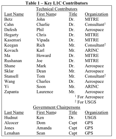
The L1C signal design is amazing, not only because of its highly evolved and outstanding technical performance but also because a committee designed this racehorse of a signal rather than it becoming a camel. Table 1 lists key members of the L1C technical committee in alphabetical order. The list has two groups, technical contributors and government chairpersons. When each new signal aspect is introduced, the key contributor or contributors from this list will be identified.
Table 1. Key L1C contributors.
L1C is intended to be interoperable with L1 signals from other GNSS providers. To identify its signal type, we note that Galileo officials have identified three types of services, “open”, “commercial”, and “publicly regulated”. An open service is freely available to all users. A commercial service is limited to users who pay a fee to access the signal, which otherwise is denied by encryption. A publicly regulated service (PRS) also is encrypted but intended only for public safety applications. GPS is adopting the open service definition but will continue to distinguish encrypted signals as “military” because there are no encrypted commercial GPS services. L1C will be a new GPS open service signal, joining L1 C/A, L2C, and L5.
Although the term “civil signal” often is used, there can be confusion about its meaning. Within the U.S. government it is common to use the word “civil” to mean civil government agencies, e.g., the Department of Transportation (DOT). However, it’s clear the GPS C/A, L2C, L5, and L1C signals are “open” and intended for use by anyone. Therefore, we will use the term “civilian” or “open” in order not to imply that any of these signals is restricted in its use.
L1C Signal Development
The L1C signal structure has evolved from the earliest GPS signals first launched in 1978. It shares with the C/A signal the L1 center frequency of 1575.42 MHz, coherence between the carrier frequency, the code clock rates, and the data rate, and the provision of a navigation data message. Significant improvements have been inherited from subsequent developments, specifically WAAS, L5, and L2C. For GPS or GPS-related signals, WAAS was the first to use forward error correction (FEC) for its data. L5 was the first open signal design to use longer spreading codes (10,230 chips), to have separate data and data-less (pilot carrier) signal components, to employ an improved navigation message structure (CNAV), and to employ overlay codes to achieve a longer equivalent code length, improve correlation performance, and eliminate the need for bit synchronization. The L2C signal adopted most of these improvements but, instead of an overlay, substituted a much longer pilot carrier spreading code, not only to optimize correlation performance but also to decrease the number of time ambiguities after tracking the spreading codes, i.e., extend the duration of GPS time ambiguity from 1 ms after tracking the C/A code and 20 ms after tracking the L5Q code to 1.5 sec for L2C.
Before giving details of the L1C signal in which we identify the primary contributor(s) for each innovation, it’s appropriate to recognize the special contributions of two members of the L1C technical team.
The first is Dr. Charles R. (Charlie) Cahn. Cahn has been a major contributor to GPS since before GPS was conceived. In particular, he was a key contributor to the Air Force 621B program which anticipated GPS. (He, Dr. James J. (Jim) Spilker, Dr. Robert Gold, and Mr. Burt Glazer deserve most of the credit for developing the original GPS C/A and P code signal structures, other than the NAV message.) Cahn discussed the merits of having a separate data-less or pilot channel in a 621B report [1], with Stansell he again recommended this for GPS in a 1975 Spartan Study Report, and finally the idea was adopted by the RTCA for L5 in accordance with recommendations from Cahn, Stansell, and Keegan. Also, Cahn was the first to recommend an overlay code on the L5 data signal to eliminate the need for the always problematic bit synchronization process. In a step toward L1C, Cahn was a primary contributor to the L2C design. In particular, he designed the code generators, including the 1.5 sec pilot code, and the chip by chip multiplexing technique which permitted two signal components in one bi-phase signal. In addition to consulting for The Aerospace Corporation and several commercial GPS companies, Cahn recently invented a more effective method to combine multiple signals on one carrier, called Phase-Optimized Constant-Envelope Transmission (POCET) modulation [2]. It is expected to be used on later versions of GPS III satellites to improve transmitter efficiency.
The second special recognition is for Dr. John Betz. Betz has played a very significant role for more than a decade in helping define the military M-code, in working with international partners to define and negotiate compatibility and interoperability signal parameters, in helping negotiate a significant part of the 2004 EU/US agreement, and in evaluating and supporting a wide variety of GPS programs and initiatives. Betz was a vital contributor to the overall L1C design through interaction with other team members, development of ways to compare alternatives, suggesting use of new signal processing concepts, and bringing experts from MITRE who performed significant analyses and developed key signal components.
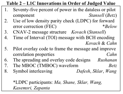
Table 2 lists, in order of the authors’ judgment of value to user communities, the most important new characteristics of the L1C signal. The list also shows the primary contributor(s) for each characteristic.
Table 2. L1C Innovations in order of judged value.
Improvements made to the previously modernized civilian GPS signals, L5 and L2C, were a starting point for the L1C design. These included: having a pilot carrier; longer spreading codes (10,230 chips minimum); overlay or long pilot codes to eliminate the need for bit synchronization, to improve correlation properties, and to decrease the number of time ambiguities aft
er locking to the spreading codes; use of FEC to improve data demodulation performance and provide bit synchronization; and the flexible and higher precision CNAV message. The following paragraphs describe the additional improvements incorporated in L1C.
A key issue was whether additional signals could be added to the L1 carrier without negatively impacting legacy signals. Several combining methods were considered, and it was determined that, with the right combining technique, L1C could be added without detriment. Use of POCET, subsequently invented by Cahn, will further enhance this capability.
An “industry standard” rate ½ constraint length 7 convolutional coding method had been adopted for forward error correction (FEC) on WAAS, L2C, and L5 signals. However, the team agreed it was appropriate to consider other possibilities. Betz arranged for Ma to address the team on at least two occasions, providing a good tutorial on other advanced FEC methods which would allow message demodulation at even lower signal-to-noise ratios.
While the FEC options were being considered, another breakthrough occurred. Since at least 1999 Stansell had encouraged development of a way to take better advantage of GPS message redundancy. Rising to this challenge, Kovach proposed a modification of the CNAV message structure that he and Art Dorsey (Lockheed-Martin) had developed for L5 and L2C. The modified message, called CNAV-2, is equally flexible, equally precise, but more efficient, allows faster time to first fix (TTFF), and permits message demodulation at signals as weak as the carrier can be tracked. This final attribute requires FEC encoding of entire message blocks (sub-frames) rather than having the continuous process used for L2C and L5. As a result, when signal levels are very weak, bit symbols from two or more messages can be combined to improve the energy available per symbol, i.e., the L1C data demodulation threshold can be improved by combining symbols from two or more messages.
As a result of the message format improvements and performance evaluations by Shane, the team settled on the Low Density Parity Check (LDPC) FEC block encoding technique. This technique is as effective as turbo codes but without intellectual property constraints. Software developed by Shane was used by Sklar and Wang to define the specific L1C implementation, with performance simulation help from Kasemsri and Zapanta.
The most important new attribute of L1C resulted from a proposal by Betz to take advantage of the improved FEC and message redundancy attributes of L1C by having two separate data messages. Half the total signal power would be in the pilot carrier and the other half would be split evenly between two messages, one with full precision and the second with less precision but which could be acquired more quickly for faster TTFF. Stansell appreciated the opportunity for less power in the message but recommended that instead of having a second message the saved power should be added to the pilot carrier, for a 75/25 split between pilot and data power. The reasoning was that code and carrier measurements on the pilot are vital to navigation whereas messages are redundant, slowly changing, and are becoming available from other sources, such as the Internet and from cell phone networks. The issue was settled by an international survey of manufacturers, universities, and government organizations. The final L1C signal design, with the 75/25 power split, was selected by these experts from a group of five signal options.
Another L1C message innovation came about through a collaboration between Kovach and Cahn. The idea was to have a separate message sub-frame with very powerful encoding to identify GPS time of week to within a two hour interval. The sub-frame is called Time of Interval (TOI), and Cahn recommended a 52 symbol (26 bit) BCH code to provide the 9 bits of TOI information. Although orbit parameters may be available from a number of sources, precise and unambiguous time is vital for navigation, and TOI serves this and other purposes. With this level of encoding, TOI can be obtained from just one message at very low signal levels. Furthermore, the identical TOI is broadcast from every GPS satellite at the beginning of every 18 second L1C message. Therefore, it is possible to combine symbols from two or more GPS signals to demodulate TOI even under very adverse signal conditions. After locking to the pilot code and its overlay, one TOI establishes time of week within ±1 hour for all GPS signals.
TOI is particularly effective because of a recommendation by Cahn to overlay the pilot spreading code with another code which frames the entire data message. The L1C overlay code is 18 seconds long (the message length) and is unique to each GPS satellite. Because of this, the TOI defines which of the 400 possible 18 second intervals within a 2 hour time span begins at the next message frame, which also is the beginning of the next overlay code. If receiver time is known or can be determined to within an hour, TOI and the GPS spreading codes establish time for all GPS satellites.
Although it would have been adequate to adopt spreading codes from the L5 signal design, Betz introduced Rushanan to the L1C technical team and recommended that he study alternate code structures with improved characteristics. After an extensive study, Rushanan recommended a set of length-10223 Weil-codes extended with a fixed 7-bit pad to provide the primary L1C spreading codes. These codes have improved performance characteristics, as detailed in [3], [4], and [5]. In addition, the team asked Rushanan to define the 1800 chip pilot overlay codes, also described in [3], [4], and [5]. Stansell specifically requested that Rushanan optimize the ability to synchronize to the overlay code with as little observation time as possible. As a result, within one or two seconds after a signal is acquired, its 18-second time frame is established. After the first satellite is acquired, the maximum time difference for signals from other satellites is less than ±10 ms for receivers near the earth, so only two possible states of the overlay code must be examined to resolve the 18 second message phase for any other satellite. If the GPS almanac, an estimated position, and even a rough time estimate are available, as usually is the case, message time phase can be resolved even faster for subsequent signal acquisitions.
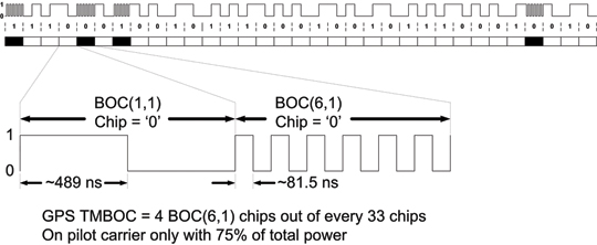
The L1C waveform originally was to have been a pure BOC(1,1) (a 1.023 MHz square wave modulated by a 1.023 MHz spreading code). Negotiations between the U.S. and the European Union (EU) at that time resulted in an agreement [6] that both GPS and Galileo would use a baseline BOC(1,1) signal. However, the EU reserved the right to further optimize their signal within certain bounds. Some of the optimization proposals were known as CBCS and CBCS. However, in further EU/US discussions it was decided that L1C and the Galileo E1 open service signal should have identically the same spectrum. This was a significant challenge because of different baseline signal structures and existing designs. The breakthrough came when Betz proposed what is called MBOC. The MBOC waveform has 10/11th of its power in BOC(1,1) and 1/11th in BOC(6,1). However, L1C and E1 OS achieve this result in very different ways. The Galileo technique is called CBOC, as described in a number of papers. [8], [9], and [10]. The GPS technique is called TMBOC and is defined by IS-GPS-800A [11] as well as by [3], [4], [5], and [8]. Whereas Galileo has a 50/50 power split between pilot and data and includes the BOC(6,1) component in each, GPS includes the BOC(6,1) waveform only in the pilot component by modulating four of every 33 spreading code chips with a 6 MHz square wave and 31 chips with a 1 MHz square wave. With 75% of the power in the pilot, the result is 3/4 x 4/33 or 1/11, as required. It is likely the BOC(6,1) signal component will be ignored by consumer grade GNSS receivers where a narrow RF bandwidth is preferred. Fortunately that is a loss of only 12% (0.56 dB) of the L1C pilot power. However, for commercial and professional grade receivers, the extra waveform transitions (wider Gabor bandwidth) can be used to improve code tracking signal-to-noise ratio, and with certain advanced techniques it should be possible to improve multipath mitigation. This final point depends on careful control or calibration of the transmitted code timing and symmetry.
Finally, Dafesh recommended that the team consider data symbol interleaving. The team accepted this suggestion, and Sklar and Wang designed the interleaver. Because of the powerful FEC, by scattering data symbols throughout sub-frames 2 and 3, it is possible to recover an entire message even if portions are blocked by, for example, walking or driving past trees or other obstructions.
All team members deserve credit for sharing, challenging, and improving concepts. Particular examples are the strong aviation navigation background provided by Hegarty and the in depth design experience for a wide range of receiver types and civilian applications provided by Keegan. In addition, Yi had the primary responsibility for documenting L1C in IS-GPS-800.
It also is important to recognize the contributions of the many professionals who responded to the worldwide survey of manufacturers, universities, and government experts. Stansell conducted each of the survey presentations, some in person and others over the Internet. One or more of the Government Chairpersons also participated, usually Hudnut or Lenahan. There were responses from organizations in 10 countries: Japan (34), the USA (26), Russia (7), the United Kingdom (5), Canada (4), Australia (1), Finland (1), Germany (1), Switzerland (1), and Taiwan (1). This is not a complete picture because a number of the responses were from individual experts while others were a consensus response from a larger group. Five signal design options were presented, and the preferred design received 62 percent of the 81 responses. As a result, the L1C signal has a 75/25 split between pilot and data power and the data rate is 50 bits per second.
L1C Signal Description
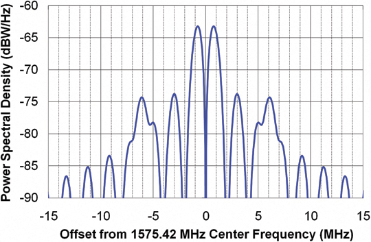
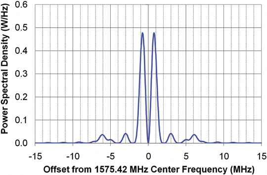
The official L1C signal description is given by IS-GPS-800; the most recent version A was released on June 8, 2010. Figures 1 and 2 show the L1C power spectral density with, respectively, a logarithmic (dBW/Hz) scale and a linear (Watts per Hz) scale. Figure 3 is the same as Figure 1 but also includes the C/A and M Code signals; it assumes both signals are transmitted with the same total power.
Figure 1.Figure 2.Figure 3.
These plots illustrate three important aspects of the L1C spectrum. First, L1C is designed to have only a small impact on reception of the legacy C/A signal. This is important for the compatibility of signals with respect to each other. A good way to evaluate the impact of one signal on another is called the Spectral Separation Coefficient (SSC), which quantifies the amount of interfering power from one signal to another, under the assumption that each signal is transmitted with the same power but with different spreading codes.
The SSC between a C/A signal and the L1C signal is –68.3 dB/Hz. The spectral separation illustrated in Figures 1, 2, and 3 assures that L1C signals will have very little impact on acquiring and tracking the legacy C/A signals. Therefore, L1C is judged to be compatible with the C/A signal.
Figure 3 also illustrates that L1C and the M Code signals have very little impact on each other. The SSC between L1C and M Code is –82.8 dB/Hz. This is important because M-Code power may be substantially higher than the civilian signals, so a larger negative SSC is important to maintaining compatibility.
The third aspect of the L1C spectrum is the additional signal power at ±6.138 MHz. This component of signal power differentiates a binary offset carrier BOC(1,1) waveform from the L1C multiplexed BOC or MBOC waveform. Exactly 1/11th of the L1C signal power is a BOC(6,1) component, whereas 9/11th of the power is a BOC(1,1) component.
75 Percent in the Pilot Carrier. Figure 4, which shows the required post-correlator C/N0 required to phase track either the L1C or C/A signals as a function of tracking loop bandwidth, illustrates the main advantages of having 75 percent of the L1C signal power in the pilot component. The carrier-tracking threshold for equivalent signal power using a Costas loop is 6 dB worse than tracking with a phase-locked loop (PLL). A Costas loop is needed for the C/A signal because it is modulated by data, whereas a PLL can be used for the dataless L1C pilot signal. This 6 dB advantage more than compensates for having only 75 percent (-1.25 dB) of the L1C power in the pilot. The vertical displacement between the two curves illustrates the 4.75 dB L1C tracking threshold advantage.
Figure 4. Required post Correlator C/N0 versus tracking loop bandwidth.
The horizontal displacement of the curves shows another L1C advantage. For a given C/N0 threshold, the L1C loop bandwidth can be increased by a factor of three. In turn, this allows tracking with G forces 32, or nine times higher. For third-order loops capable of tracking acceleration, this allows tracking with 27 times higher jerk. Such differences are likely to be more important than tracking threshold for high-dynamic applications such as machine control.
Although Figure 4 assumes the L1C and L1 C/A signals have the same total power, the minimum received L1C signal power specified in IS-GPS-800A is –157 dBW, and the equivalent for C/A in IS-GPS-200E is –158.5 dBW. In other words, the intent is for L1C to be transmitted with 1.5 dB more power than C/A. Therefore, the figure is conservative by 1.5 dB in evaluating the L1C advantages over C/A. Thus, the actual threshold advantage is 4.75 + 1.5 = 6.25 dB.
For narrowband or other receivers not punctual correlating the BOC(6,1) signal component, the pilot carrier is 29/33 or 0.56 dB weaker, so the net advantage is 4.75 – 0.56 + 1.5 = 5.69 dB.
LDPC Block Encoding
Low-density parity check (LDPC) encoding provides three key advantages. First, to demodulate the critical part of the L1C message with a bit error rate (BER) of 10-5 requires an Eb/N0 (ratio of energy per bit to the noise power in a 1-Hz bandwidth) of 2.2 dB versus 96 dB for the C/A signal. When taking into account that only 25 percent of L1C signal power is in the data component, the required total power of the L1C signal can be 1.4 dB less than the C/A signal for an equivalent BER. As a result, this performance allows the pilot component of L1C to have 75 percent of the total L1C power.
Second, LDPC gives near-optimum performance with no intellectual property constraints. Third is the ability to block-encode Subframes 2 and 3 of the L1C message, described next.
CNAV-2 Message. Figure 5 compares the L5 and L2C CNAV message structure to the L1C CNAV-2 structure. CNAV was a major step forward compared to the original NAV message in terms of flexibility, precision, time to first fix (TTFF), and integrity. Instead of the fixed 30-second structure of the NAV message, CNAV consists of multiple six-second messages that are differentiated by a message-type number. The sequence of broadcast message types is defined by the GPS control segment, which greatly improves flexibility. The round-off error in the NAV message can affect pseudorange calculations
by up to 40 centimeters, whereas the equivalent CNAV error contributes about 3 centimeters. Orbit and clock precision is substantially improved. Because a minimum of three message types are needed for the necessary orbit and clock parameters, as little as 18 seconds is needed to gather the necessary information after locking to a signal. On the other hand, if four message types are being sent sequentially, and the receiver locks just after the beginning of a message, it can take 30 seconds to gather the necessary data. TTFF typically is improved. Importantly, each CNAV message includes a 24-bit cyclic redundancy check (CRC) word that makes it practically impossible to have bit errors in a message that passes the CRC check.
Figure 5. CNAV and CNAV-2 message structures.
CNAV-2 improvements to the CNAV structure all but guarantee an 18-second TTFF after signal acquisition. Message efficiency is improved by eliminating the need to identify each six-second message, to have complete time-of-week (TOW) information in each six-second message, and to have three rather than two 24-bit CRC words every 18 seconds. Even more important, GPS time is defined modulo 18 seconds upon acquisition of only one signal, and it is defined modulo two hours by decoding only one 26-bit, 0.52-second time-of-interval (TOI) word at the beginning of each message. In addition, TOI is so well encoded (52 symbols for nine data bits) that it can be demodulated in very weak signal conditions, which can be further enhanced by combining the identical TOI symbols transmitted by every satellite at the beginning of every 18-second message.
Figure 6 illustrates the ability to combine message symbols from several sequential Subframe 2 data blocks so vital clock and ephemeris data can be demodulated at the weakest signal level the receiver can track. This feature is made possible because the symbols in subframe 2 will not change for at least 15 minutes (50 repeats) and typically no more often than one to two hours (200 to 400 repeats). This provides up to 8.4 dB of message demodulation improvement. The figure also shows other L1C improvements: 4.8 dB of carrier track threshold extension, and a TTFF of 18 seconds after successfully demodulating subframe 2 from the minimum number satellites for a position fix.
Subframe 3 of the L1C message contains less time-critical information such as almanac, ionospheric correction terms, and so on. This subframe also is LDPC block-encoded so it is quite robust, although it does not offer the ability to combine symbols from sequential messages.
Figure 6. L1C and C/A performance comparison.
Pilot Overlay Code
Figure 5 shows that the pilot overlay code consists of 1,800 chips that frame the 18-second message. In comparison with the L5 20-millisecond (ms) pilot overlay code, it not only is 900 times longer but also is unique to each satellite. This improves cross-correlation performance in general and particularly when two satellites have the same pseudorange.
The long L1C overlay code can be acquired reliably after only one or two seconds of signal lock. Its length does not cause a relevant delay in TTFF, but it provides many advantages. First, synchronizing to the overlay code on one satellite defines GPS time for all satellites modulo 18 seconds (in comparison to 1 ms with the C/A code). Even with infrequent use, the receiver’s RTC, which typically is better than 5 parts per million (ppm), should have sufficient accuracy — better than ± 9 seconds — to completely resolve GPS time with one signal acquisition. In 24 hours with a clock frequency error of 5 ppm the time drift would be less than ½ second.
Even if the RTC is in error by several times 18 seconds, resolving accurate time can be done quickly by computing position fixes with multiple time hypotheses spaced 18 seconds apart. Pseudorange changes at rates up to ±1,440 kilometers per 18 seconds. Because some satellites are approaching, others are moving away, and all of them are changing range at different speeds (different Doppler frequencies), determining which position fix is correct out of several 18-second GPS time hypotheses will be straightforward since only one will be reasonable. (Care must be taken to avoid any extremely rare instances where two results may seem reasonable.)
The worst clock error with aided GPS (A-GPS) is ±2 seconds, which is adequate to completely resolve GPS time after acquiring only one L1C signal. This capability can aid acquisition of and navigation with other signals, such as C/A or signals from other GNSS providers. The 18-second overlay code will provide benefits as soon as even a few L1C signals are available.
The L1C overlay code, in conjunction with the repeating symbols of message subframe 2, also enables data demodulation to begin at any point within an 18-second message. It is not necessary to wait for the message frame to begin. The receiver can begin collecting data symbols at any time, and 18 seconds later it will have assembled all the subframe 2 clock and ephemeris information and can begin to navigate. An exception occurs when the satellite message is updated, between once every 15 minutes to once every two hours. This capability significantly improves TTFF whenever satellite messages are needed for navigation, for example, when they aren’t still valid from a previous collection or aren’t provided by an A-GPS service.
Spreading and Overlay Code Designs
The L1C MBOC waveform (time-multiplexed BOC, or TMBOC), shown in Figure 7, enabled GPS and Galileo to have open-service L1 signals with an identical spectrum, although implemented quite differently. L1C places all the BOC(6,1) chips in the pilot carrier. This is because the BOC(6,1) component is intended to improve code-tracking performance by increasing code loop signal-to-noise ratio (SNR) and by allowing advanced multipath-mitigation techniques to have the advantage of more code transitions. Because these measurements are made almost exclusively on the three times (4.8 dB) more powerful pilot signal, there is no reason to lose the code tracking benefit by having BOC(6,1) chips in the data signal component. In addition, narrowband receivers such as those predominantly used for consumer applications cannot process BOC(6,1) chips, so it would be undesirable to deny full message signal power to such receivers.
Figure 7. The GPS MBOC (TMBOC) modulation.
For receivers tracking only the BOC(1,1) component of L1C MBOC, there are on average 43.5 code transitions per 33 chips. For those tracking both components, there are on average 89.5 code transitions per 33 chips. This provides up to 3.1 dB of improvement in code loop SNR for wideband receivers code tracking with both types of chips. (The amount of improvement depends on receiver RF bandwidth.)
Classic multipath-mitigation techniques such as the double-delta don’t work well with the BOC(6,1) waveform, but recent advances promise improvement by using the extra transitions in the MBOC signal. Some developers worry that the full benefit may not be achieved unless code symmetry and time alignment of the two components is better than the signal specification permits. If the satellites cannot provide the needed signal symmetry and alignment, such problems likely can be overcome by ground calibration of these characteristics, either directly by each receiver or indirectly by an observing network.
Symbol Interleaving. Symbol interleaving means that before a message is transmitted, the satellite scatters the 10-ms message data symbols from subframes 2 and 3 throughout these subframes in
a fixed and known pattern. After a receiver has demodulated (or otherwise measured) the symbols belonging in a subframe, they are reassembled into the proper order before the LDPC block decoding is performed. In other words, the scattering done in the satellite is undone by the receiver. The objective is to provide a measure of protection against certain types of signal fading. For example, if a sequence of symbols from the satellite is lost because the receiver passes behind an object such as a tree, only half the symbols in this part of the message would be affected if the adjacent symbols in the original message are received either before or after the signal blockage. Thus, with reasonable signal levels and the benefit of powerful LDPC block encoding, the entire message could be reconstructed.
Performance Metrics and Comparison
A main objective for the L1C signal structure was to significantly improve the autonomous navigation capability for GPS users. Key weaknesses in the current C/A signal include the thresholds for bit synchronization, message synchronization, and data-bit demodulation. To achieve navigation at very low signal levels, users of the L1 C/A signal had to employ external sources for time synchronization, data acquisition, and, to extend the tracking loop threshold, external data-bit aiding to enable phase-locked tracking rather than Costas tracking of the C/A signal. The new signal structure addresses all of these shortcomings and provides a robust autonomous navigation system that requires no external aiding for most commercial applications.
Message Frame Synchronization and Time of Transmission. For autonomous navigation, frame synchronization has two important roles. The first is to set GPS time, modulo frame duration, which is required to establish the unambiguous time of transmission. Frame synchronization, or knowledge of frame start, also enables assembly of the received bits into the appropriate data words. In both L1 C/A and L5, frame synchronization is accomplished by recognizing a synch word within a data subframe, which requires accurate demodulation of data bits. For L1C, frame synchronization is inherent in the signal structure and does not require demodulation of data bits. This is very important for two reasons. The first is to establish GPS time of transmission very quickly, especially when the satellite message is not needed, for example, if it was acquired previously or obtained by other means. The second is when satellite ephemeris data is necessary, but the signals are very weak. The L1C message structure facilitates this capability.
Overlay Code on Pilot Carrier. One frame of data consists of 1,800 symbols modulated onto the data carrier which, at 100 symbols per second, is 18 seconds long. However, synchronized to this 18-second data frame is a pseudorandom code modulated on the dataless pilot carrier. This 100 chips per second overlay code is a linear-shift-register code that is truncated to be 1,800 chips long. The overlay codes were chosen to have very low minor auto-correlation and cross-correlation peaks so a very short segment of the code can be used to establish its underlying code phase.
If a 100-chip segment of the received code is correlated over a replica of the entire code, the proper correlation peak would be easily distinguished, thus establishing the GPS time epoch at the start of the code. Since this code epoch and the start of the data frame are synchronized, the start of the entire data frame is established, modulo 18 seconds. The start of the data frame by definition establishes the GPS time of transmission, also modulo 18 seconds. This is accomplished without decoding a single data bit by using the power advantage of the pilot carrier.
However, using the message to resolve the 18-second time ambiguity often is not needed. For example, the receiver’s real time clock (RTC) is likely to be accurate to within ±9 seconds. Alternately, almost any source of external aiding can provide time to within ±2 seconds. In either case, if the receiver already has a valid satellite ephemeris, navigation can begin after receiving a little over 1 second of the stronger pilot carrier signal. Ephemeris data can be available in a number of ways, including prior reception from the satellite, from a separate communications channel, or from one of several predicted ephemeris sources.
Message Frame – Data Format. A message frame consists of 1,800 symbols that comprise two distinct data types. The first data type, in subframe 1, is the Time of the Frame (TOI or Time of Interval) modulo two hours. The second data type is further separated into two blocks, subframe 2 containing data that is fixed for a period of time and subframe 3 containing data that can change from frame to frame.
Time of Interval Subframe. The TOI is a count of the number of 18-second message intervals in each 2 hour time period. Two hours is the maximum duration of any ephemeris message before being replaced by the satellite. (Fifteen minutes is the minimum.) There are 400 18-second intervals in 2 hours, so it requires 9 bits to represent the 400 intervals. These nine bits are block-encoded into 52 symbols using a BCH(51,8) code, where the 8 data bits are the least significant bits of the TOI. The most significant bit (MSB) of the TOI is then mod-2 added to the BCH codeword and also appended to the resulting codeword as its MSB, resulting in a 52-symbol codeword. This coding provides a BER of 10-5 for an Eb/N0 of –1.9 dB per coded symbol or a C/N0 of +18.2 dB-Hz at the correlator output for the data channel. Since the data channel contains only 25 percent of the total L1C power, the C/N0 of the composite signal would be +24.2 dB Hz. Symbol demodulation is performed using the pilot carrier tracked by a PLL as the phase reference. Since the pilot carrier contains 75 percent of the total power, its C/N0 would be +23 dB-Hz. With a (single-sided) loop-noise bandwidth of 10 Hz, the loop SNR for the carrier channel PLL would be +10 dB.
Note that a 10-5 BER is not required for successful demodulation of TOI. Therefore, weaker signals can be used successfully if the PLL loop bandwidth can be smaller in such weak signal conditions.
The most straightforward method to decode the TOI is brute force maximum likelihood estimation. All possible code words for the 400 possible data words can be pre-computed. Each then can be compared (correlated) with the received code word. The data word that corresponds to the code word with the highest correlation would be the result of the decoding process.
Finally, since all satellites simultaneously transmit the same TOI, the received code word from several satellites can be combined to increase the effective Eb/N0. The target BER of 10-5 thus can be achieved at an even a lower C/N0 than the single satellite value. In this case, the decoding process described above can be performed on a composite code word derived from two or more satellite signals, weighted appropriately for the signal strength from each one.
As an example, consider a receiver with access to an external source of the ephemerides. By combining the TOI code word from five satellites, the average C/N0 required per satellite would only be 17.2 dB-Hz, so time could be established to ±1 hour in slightly over 1 second.
Because of the 18-second overlay code, decoding TOI is not required for receivers with an internal clock good to ±9 seconds or with external time aiding, the worst of which today is within ±2 seconds.
Data Subframes. The remaining data bits are separated into two additional subframes. (TOI is in the first subframe.) The second subframe contains data that does not change for at least 15 minutes, and typically for an hour or two. This subframe provides the satellite ephemeris and the interval time-of-week (ITOW) count, which identifies the start time of the two-hour interval since the beginning of the GPS week, which, in turn, frames the TOI count of 18-second intervals within each two-hour frame. The third subframe contains data that normally changes from frame to frame, such as the satellite constellation almanac.
The block of data containing the satellite ephemeris (subframe-2) consists of 576 clock and ephemeris bits along with a 24-bit CRC, for a total of 600 bits. These are encoded with a rate-½ LDPC Block code into 1,200 symbols. The block of data containing variable data (subframe-3) consists of 250 data bits along with a 24-bit CRC, for a total of 274 bits. These are also encoded with a rate-½ LDPC Block code into 548 symbols. The 1,748 symbols of the two data subframes are combined and interleaved using a simple 38 x 46 row-column block interleaver. These interleaved symbols plus the 53 TOI symbols make up the entire 1,800-symbol (900-bit) message frame.
Since both the LDPC codes and the interleaver operate on independent blocks of data, the resulting symbols for subframe-2 are identical and in the same location in each message frame for between 15 minutes and two hours. Since the data decoding uses the pilot carrier as the phase reference, the subframe-2 symbols can be coherently combined over many 18-second message frames before decoding to improve BER performance.
One reasonable subframe-2 strategy would be to check the CRC after LDPC-decoding the first received message to determine if there are any remaining bit errors. If errors are detected, do the same with the second message. If errors exist in the second message, coherently combine the symbols from the two messages, properly weighted, LDPC-decode the combination, and check the resulting CRC for errors. If necessary, this process can be used on as many messages as needed to obtain a perfect result.
Framing the data messages with the pilot overlay code and the repeating characteristic of subframe 2 permits data collection over any arbitrary 18-second interval. It doesn’t matter where data collection begins. The overlay code tells the receiver which symbol is which, and the repeating subframe-2 message can be compiled from any place in the previous message to the same place in the following message. The powerful CRC assures that a good message is perfect. When the ephemeris is needed from a satellite, rather than from an alternate source, these characteristics allow TTFF to be slightly over 18 seconds, with assurance the information is correct.
Since LDPC FEC has been adopted by the current state-of-the-art wireless standards such as 802.11n and 802.16e, employing it in the latest GPS signal structure should be simple for the receiver designer. In fact, synthesizable cores are available for WiMax LDPC decoders from several sources, and LDPC decoders are as commonplace in wireless signal basebands as Viterbi decoders for the convolutional codes of L2C, L5, and SBAS have become in GPS basebands.
For subframe-2 data, the Eb/N0 required to achieve a BER of 10-5 is approximately 2.2 dB. For subframe-3 data, the Eb/N0 required for this same performance is approximately 2.7dB.
Signal Structure
The L1C signal is a composite of two signals that are phase/frequency coherent with synchronized spreading codes and symbol timing. The pilot signal has 75 percent of the total power, is a carrier-only signal, and is spread by a 10-ms long code plus an 18-second overlay code. The data signal has 25 percent of the total power, is spread by a 10-ms long code, and is data modulated with 10-ms symbols.
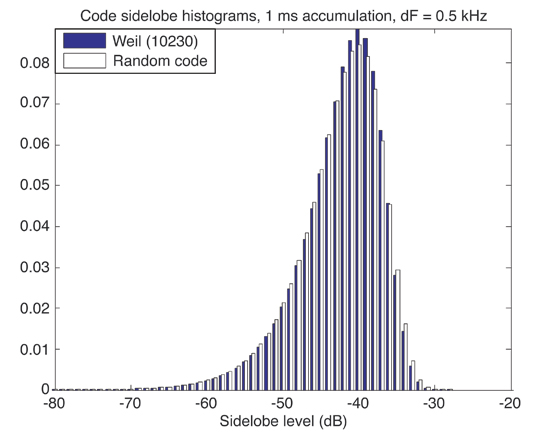
Spreading Codes. The spreading code for both L1C signals are 10,230 chip codes with a chip rate of 1.023 MHz, producing a 10-ms long code. This corresponds to one symbol for the data carrier and one chip of the overlay code for the pilot carrier. These codes are not linear shift register sequences like all other codes employed by GPS, but are pseudo-random sequences derived from Weil sequences of length 10223. This sequence is extended by a 7-bit sequence 0110100, which is the same for all satellites, to the required length of 10230. The location within the particular Weil sequence where the extension sequence is inserted is called the insertion index. A pair of Weil indices and a corresponding pair of insertions points then determines the pair of codes for each satellite.
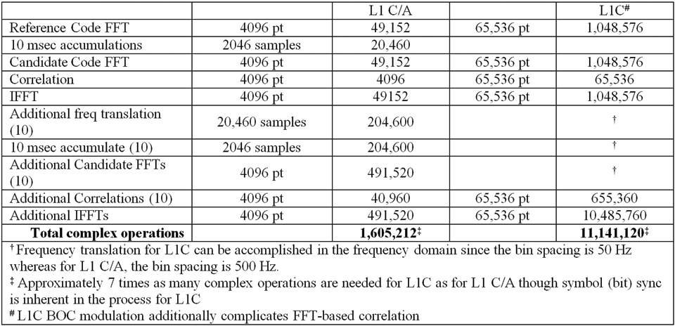
Synchronization to one of these Weil-based codes can be accomplished with a standard time-domain correlator, but the number of potential hypotheses has increased by a factor of ten compared to the C/A signal. However, this is no different than time-domain correlation for an L5 code, which also are 10,230 chips long. Synchronization also can be accomplished using FFT-based frequency-domain correlation, however it does require an FFT of length 65,536 (for a standard radix-2 implementation) since the FFT must span 2 full code periods at a minimum of 2 samples per code chip (40,920).
To compare L1C frequency domain correlation with L1 C/A, a frequency search window and integration time must be hypothesized. A simple example would be a 10-ms coherent integration time and ±250 Hz frequency uncertainty. Table 3 compares the number of complex operations required for L1 C/A vs. L1C.
Table 3. Comparison of FFT-based correlation for L1C versus L1 C/A. (Click to enlarge.)
For cases where large search window uncertainties exist, and frequency domain correlation provides a computational benefit, an alternate approach to L1C synchronization would be to first obtain L1 C/A synchronization using an FFT-based search, providing frequency and 10 timing hypotheses (perhaps more with potential cross-correlations for L1 C/A). These L1C hypotheses could be tested by simple time-domain correlation that would benefit from the much better cross-correlation properties of the L1C codes.
For cases where time uncertainty is not large, a time domain search of the L1C code would be no more difficult than the equivalent for L1 C/A. For cases where the time uncertainty is small but the frequency uncertainty is large, time-domain partial-period correlations could be combined in an FFT structure that would span a large frequency uncertainty with a single time hypothesis. For example, the 10,230 chips could be separated into 62 segments, each 165 chips long. The 62 segments could then be combined using a zero filled 64-pt FFT to produce 64 full correlations spanning ±3 kHz.
MBOC Waveform. The L1C spreading code is further modulated with a code clock synchronized 1.023 MHz square wave creating the BOC(1,1) signal that forms the majority of the L1C code symbols. This produces a code that appears as a 1 MHz square wave, synchronized to the Weil-based code edge, whose polarity indicates the state of the Weil-based code chip. This BOC(1,1) sequence modulates all of the data channel chips and 29 of every 33 pilot channel chips. The other 4 out of 33 Pilot channel chips are modulated by a BOC(6,1) code symbol in which a 6 MHz square wave is used instead of the 1 MHz square wave for the BOC(1,1) chips. (Recall that ‘1’ signifies 1.023 MHz and ‘6’ signifies 6.138 MHz.) For receiver designers who choose not to punctual correlate the BOC(6,1) component of the pilot carrier, the pilot carrier power will be reduced by ~0.6 dB.
The BOC(6,1) signal component provides an opportunity for better performance of advanced multipath mitigation techniques. The presence of multipath interference not only impacts the code-tracking process of a GPS receiver but also distorts the waveform seen by the phase-tracking process of the receiver. The distortion of the phase of the received signal is most problematic when the reflector creating the multipath signal is very close to the receiving antenna, because the path length of such a multipath signal changes very slowly. Since the path length changes very slowly, it appears as an almost constant bias error in the phase measurements. The only way to observe this distortion, and hence measure its impact on the phase measurements, is to observe the phase of the carrier very close to the code transitions. The estimate of this distortion obviously is better the more frequently it can be observed. This is particularly important because the distortion is not constant but slowly changes. The MBOC signal combination provides
just over twice the number of transitions at which to observe the phase distortion than the BOC(1,1) signal alone, which is important for higher fidelity measurements during short intervals when the slowly changing distortion is highly correlated .
L1C Status
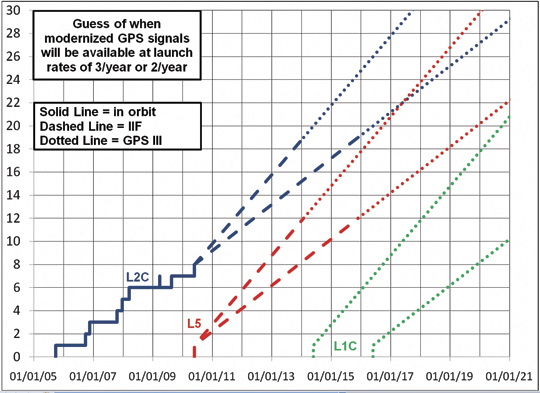
Companies already are designing L1C into their new chipsets, even though the first satellite to carry the signal is not expected before 2014. When will L1C be available from enough satellites to be meaningful? Figure 8 is a guesstimate of how modernized GPS signals will become available over the next decade. The projections assume either two or three successful satellite launches per year, and many observers think two per year may be realistic. Because GPS only launches on need to sustain the constellation, the actual launch rate depends on the lifetime of the satellites now in orbit. The first launch of a GPS III may be delayed until all IIF satellites have been launched, or the first GPS III, if available, may be launched before the last IIF to test the new design in space as soon as possible.
Some L1C signal and message characteristics will significantly benefit users of C/A and other GNSS signals by, for example, quickly resolving time for all GNSS signals. Therefore, L1C will provide meaningful benefit as soon as even one signal can be tracked from any location on earth. That might be possible with as few as six GPS III satellites in orbit, depending on where in the constellation they are deployed.
Figure 8. Guesstimate of modernized GPS signal availability.
Tom Stansell heads Stansell Consulting, after eight years with the Johns Hopkins Applied Physics Laboratory, 25 years with Magnavox (staff VP), and five years with Leica Geosystems (VP), pioneering Transit and GPS navigation and survey products. He led technical development of the GPS L2C signal and coordinated the GPS L1C project (2004–2006). He is a member of the Editorial Advisory Board of GPS World.
Ken Hudnut applies new technologies such as GPS to earthquake research as a geophysicist for the U. S. Geological Survey in Pasadena, California. He served as project manager for the GPS L1C signal design project from 2003. He received his Ph.D. from Columbia University.
Rich Keegan has 36 years of experience in radio navigation including Transit, Timation, Omega, Loran C, as well as GPS for the past 28 years. He has been the principal of a consultancy in digital communications and navigation since 2000. He was a member of the L2C and L1C modernization committees.
By Yuri Urlichich, Valeriy Subbotin, Grigory Stupak, Vyacheslav Dvorkin, Alexander Povalyaev, and Sergey Karutin
A team of authors from Russian Space Systems, a key developer of navigation and geospatial technologies in the Russian aerospace industry, describes the new L3 CDMA signal to be broadcast by GLONASS-K satellites and the progress to date in developing the SDCM augmentation system.
INNOVATION INSIGHTS by Richard Langley
IT’S NO LONGER JUST A GPS WORLD. Russia’s GLONASS, or Global′naya Navigatsionaya Sputnikova Sistema, will soon have a full complement of satellites in orbit providing positioning, navigation, and timing worldwide.
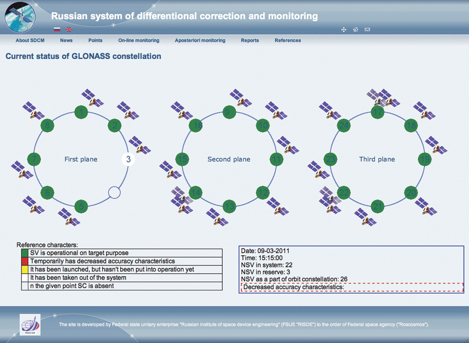
The Soviet Union began development of GLONASS in 1976 just a few years after work started on GPS. The first satellite was launched in 1982 and a fully populated constellation of 24 functioning satellites was achieved in early 1996. However, due to economic difficulties following the dismantling of the Soviet Union, by 2002 the constellation had dropped to as few as seven satellites. But the Russian economy improved, and restoration of GLONASS was given high priority by the Russian government. The satellite constellation was gradually rejuvenated using primarily a new modernized spacecraft, GLONASS-M. The new design offered many improvements, including better onboard electronics, a longer lifetime, an L2 civil signal, and an improved navigation message. The GLONASS-M spacecraft still used a pressurized, hermetically sealed cylinder for the electronics, as had the earlier versions. Today, 26 functional GLONASS-M satellites are on orbit, 22 of them in service and providing usable signals, with four more having reserve status. A full constellation of 24 satellites should be available later this year with launches of several GLONASS-M satellites and the latest variant, the GLONASS-K satellite.
GLONASS-K satellites are markedly different from their predecessors. They are lighter, use an unpressurized housing (similar to that of GPS satellites), have improved clock stability, and a longer, 10-year design life. They also include, for the first time, code-division-multiple-access (CDMA) signals accompanying the legacy frequency-division-multiple-access signals. There will be two versions: GLONASS-K1 will transmit a CDMA signal on a new L3 frequency, and GLONASS-K2, in addition, will feature CDMA signals on L1 and L2 frequencies. The first GLONASS-K1 satellite was launched on February 26 and is now undergoing tests.
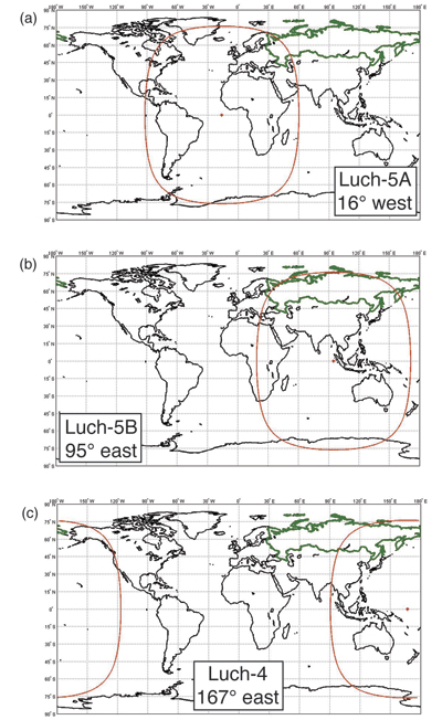
GLONASS is being further improved with a satellite-based augmentation system. Called the System for Differential Correction and Monitoring or SDCM, it will use a ground network of monitoring stations and Luch geostationary communication satellites to transmit correction and integrity data using the GPS L1 frequency. The first of these satellites, Luch-5A, will be launched this year.
In this month’s column, a team of authors from Russian Space Systems, a key developer of navigation and geospatial technologies in the Russian aerospace industry, describes the new L3 CDMA signal to be broadcast by GLONASS-K satellites and the progress to date in developing the SDCM augmentation system.
The Russian Global Navigation Satellite System (GLONASS) is once again approaching full operation. As of March, 22 satellites are in service, providing nearly continuous global coverage. These satellites are modernized GLONASS or GLONASS-M satellites, transmitting the legacy frequency-domain-multiple-access (FDMA) navigation signals in the L1 and L2 frequency bands.
The structure of the navigation signals transmitted by the satellites determines the accuracy of the pseudorange measurements, which, in turn, affects a user’s position accuracy. Evolution of the GLONASS navigation signals is a top priority for the overall system development. A new version of the satellites, GLONASS-K, will broadcast a code-division-multiple-access (CDMA) signal in the L3 band for the first time in the system’s history. In addition to the change in signal parameters, new navigation information will be transmitted to users through this signal. Further GLONASS navigation signal development assumes that a new CDMA civil signal will also become available in the L1 and L2 bands.
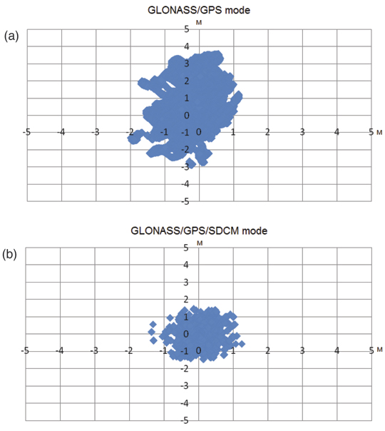
The evolution of GNSS augmentation is also an important task in the development of satellite navigation in Russia. The Russian satellite-based augmentation system (SBAS), the System for Differential Correction and Monitoring (SDCM), is entering into the deployment phase and that is why some aspects of interoperability and compatibility with other SBASs become important. Taking into account the fact that satellite channels are the most efficient and universal tool to supply GNSS users with precise ephemeris and clock parameters and the positive experience of regional systems (such as the Quasi-Zenith Satellite System), we can see the potential for the development of a precise positioning service.
In this article, we will discuss plans for modernizing GLONASS, covering both the new signals and the augmentation service.
Navigation Signals
The main task for GLONASS development is an extension of the ensemble of navigation signals. This extension means that new CDMA signals in the L1, L2, and L3 bands will be added to the existing FDMA signals. The GLONASS satellites will keep broadcasting the legacy signals until the last receiver stops working.
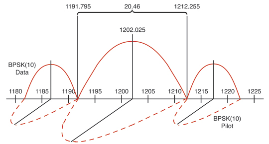
The first phase in the implementation of CDMA technology on GLONASS-K satellites includes a new signal in the L3 band on a carrier frequency of 1202.025 MHz. The first GLONASS-K satellite was launched on February 26, 2011, and is undergoing tests. The ranging code chipping rate for the CDMA signal is 10.23 megachips per second with a period of 1 milliseconds. It is modulated onto the carrier using quadrature phase-shift keying (QPSK), with an in-phase data channel and a quadrature pilot channel. The signal spectrum is shown in Figure 1.
Figure 1. L3 CDMA signal spectrum (frequencies in MHz).
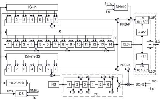
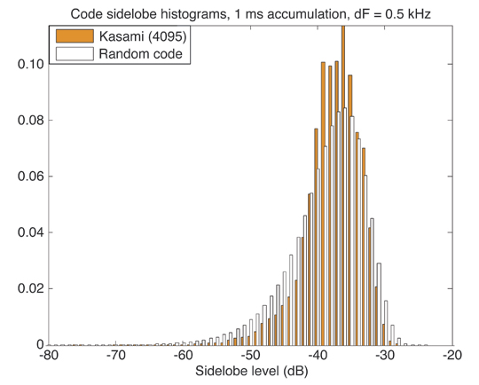
A block diagram of how the GLONASS L3 signal is formed is presented in Figure 2. The set of possible ranging codes consists of 31 truncated Kasami sequences. (Kasami sequences are binary sequences of length 2m – 1 where m is an even integer. These sequences have good cross-correlation values approaching a theoretical lower bound. The Gold codes used in GPS are a special case of Kasami codes.) The full length of these sequences is 214 – 1 = 16,383 symbols, but the ranging code is truncated to a length of N = 10,230 with a period of 1 milliseconds and with the following initial state (IS) in the generator (G) registers: G2 – IS = 00110100111000, G1 IS = n, G3 IS = n + 32. It these equations, n is the system number of the satellite in the orbit constellation. For these codes, inter-channel jamming is about –40 dB.
Figure 2. Formulation of L3 CDMA signal.
The navigation message symbols (NSs) are transmitted at a rate of 100 bits per second with half-rate convolution coding (CC) with a memory of 6. This means that the duration of an NS is 10 milliseconds and the duration of the CC symbols is 5 milliseconds. The CC switch (see Figure 2) should be in the lower position for the first half of each NS.
The pseudorandom sequence of the L3 data signal, PRS-D, is modulo-2 summed with a periodic 5-bit Barker code (BC = 00010) b
efore phase modulation. Barker code symbols have a duration of 1 millisecond and are synchronized with the pseudorandom code symbols. The pseudorandom sequence of the L3 pilot signal, PRS-P, is modulo-2 summed with a 10-bit Neuman-Hoffman code (NH = 0000110101). The Neuman-Hofman code symbols have a duration of 1 millisecond and are synchronized with the information symbols. The Barker and Neuman-Hoffman codes are used for CC synchronization in the L3 user’s receiver (see Further Reading for background details).
The navigation message superframe (2 minutes long) will consist of 8 navigation frames (NFs) for 24 regular satellites in the GLONASS first modernization stage and 10 NFs (lasting 2.5 minutes) for 30 satellites in the future. Each NF (15 seconds long) includes 5 strings (3 seconds each). Every NF has a full set of ephemerides for the current satellite and part of the system almanac for three satellites. The full system almanac is broadcast in one superframe. A time marker is located at the beginning of a string and given as a number of a string within the current day in the satellite time scale.
The GLONASS system and the satellites’ time scales are coordinated with the Russian national time scale, UTC(SU), which is periodically adjusted for a leap seconds. A special flag, A, is used in each frame to inform users about an anomalous fifth string of this frame. If А = 0, the fifth string will be normal with a 3-second duration; if А = 1, the fifth string will be either 2 seconds or 4 seconds. The correction value (+1 second or –1 second) is also transmitted in the special NF flag, KP. If KP = 11, the fifth string will be shorter due to a correction of –1 second; if KP = 01, it will be longer due to a correction of +1 second. A user should not use the short string. A string is lengthened by adding “0” to the normal string. This algorithm is implemented with the objective of simplifying the time scale correction process in user equipment.
Modulation and Multiplexing. There are intensive studies being carried out for developing new CDMA signals in the L1 and L2 bands in addition to the L3 signal described above. The main difficulties to be overcome in these studies are to ensure a low-power spectral density (PSD) of –238 dBW/m2/Hz in the 1610.6–1613.8 MHz radio astronomy band and the multiplexing of more than two signal components, providing a constant signal level.
The first task could be solved by using a modulation with a low PSD level in the radio astronomy band, such as a binary offset carrier (BOC) modulation with a subcarrier frequency of 5.115 MHz and a spreading code chipping rate of 2.5575 megachips per second (BOC(5, 2.5)) as shown in Figure 3.
Figure 3. BOC(5, 2.5) signal spectrum (frequencies in MHz).
There are two well-known methods of signal multiplexing — time multiplexing and amplitude equalizing. The time multiplexing technique is used for the GPS L2C signal, while the amplitude equalizing method is used for the composite BOC (CBOC) signals in the Galileo E1/L1 band and the alternative BOC (AltBOC) signals in E5a-E5b bands. This method has the disadvantage of about 10–16 percent loss of the transmitter power on the equalization. However, it has an advantage: simple user equipment architecture and, more importantly, the possibility of step-wise implementation of the multicomponent signal. The step-wise approach is compatible with older receivers. New user equipment will be able to track both old and new signal components, as well as a combined signal consisting of old and new components. Vector and phase diagrams for two-, four-, and six-component AltBOC signals are shown in Figure 4. Even with six components, losses are lower than about 16 percent, but it is possible to avoid any loss using time multiplexing. That is why the final decision about future GLONASS signals has not yet been made.
Figure 4. Vector and phase relationships for AltBOC signals with (a) 2-, (b) 4-, and (c) 6-components, with losses of 0, and about 15 and 16 percent respectively.
There have been extensive studies on the definition of the ensemble of code sequences with a minimum level of interchannel jamming. It was found that the jamming level for random shifts does not depend on the code type, but rather depends on the number of symbols, N, in a period. Cross-correlation functions for Kasami 4095 and Weil 10230 codes are shown in Figures 5 and 6. (Kasami codes, as previously mentioned, are being used for the GLONASS L3 CDMA signal. Weil codes are prime length sequences constructed from the well-known Legendre sequences and are used for the GPS L1C signal.) For comparison, we show cross-correlation functions for random codes with equal lengths on the same figures. It is obvious that the histograms of predefined and random codes are close to being equal. Sidelobe dispersion levels are lower than 0.1 dB.
The results obtained from the studies allow us to draw a conclusion about the invariance of the stochastic characteristics of inter-channel interference using a code structure with a fixed length of N symbols. That is why it is possible to choose an ensemble of binary code sequences on the basis of generation simplicity.
Figure 5. Kasami and random code cross-correlation functions (4,095 symbols).Figure 6. Weil and random code cross-correlation functions (10,230 symbols).
GLONASS Augmentation Development
SDCM has been under development since 2002. The main elements of the system, including the network of reference stations in Russia and abroad, the central processing facility (CPF), and the SDCM information distribution channel, have been designed.
Ground Stations. The SDCM uses 14 monitor stations in Russia and two in Antarctica at Russia’s Bellingshausen and Novolazarevskaya research stations. Eight more monitor stations will be added in Russia and several more outside Russia. The additional overseas stations may include sites in Latin America and the Asia-Pacific region.
Central Processing. Raw measurements (GLONASS and GPS L1 and L2 pseudorange and carrier-phase measurements) from the ground stations come to the SDCM CPF. The CPF calculates the precise satellite ephemerides and clocks, controls integrity, and generates the SBAS messages. The format of these messages is compliant with the international standard also used by the Wide Area Augmentation System (WAAS), the European Geostationary Navigation Overlay Service (EGNOS), and the Japanese Multi-functional Transport Satellite (MTSAT) Satellite-based Augmentation System (MSAS).
Format Limitations. The current SBAS format has a limited capability for broadcasting corrections for GLONASS and GPS satellites combined. There is space for only 51 satellites, insufficient for the current number of satellites on orbit. As a result, studies are looking into the efficiency of SDCM data broadcasting in an attempt to resolve this contradiction. The three main options are: use a dynamic satellite mask, use two CDMA signals, or provide an additional SBAS message.
Under the first option, SDCM satellites would only broadcast corrections and integrity data for those GLONASS and other GNSS satellites in view of users in the territory of the Russian Federation. For the second option, SDCM satellites would transmit two CDMA signals with independent sets of correc
tions and integrity data on each signal. The third option assumes that the SDCM data stream would have additional messages with information about satellites not included in the initial list of 51.
The first scenario is possible with the current version of the SBAS format. The other two options require some changes in the format of SBAS messages and international coordination. But the SDCM CPF is ready to operate in all of these modes.
Distribution. The main advantage of SBAS is its universal space channel to users. The SDCM orbit constellation will consist of three geostationary satellites from the multifunctional space relay system Luch (see Figure 7). Luch, which means “ray” or “beam” in Russian, will be used to relay communications between low Earth-orbiting spacecraft and ground facilities in Russia in a similar fashion to that of NASA’s Tracking and Data Relay Satellite System. The satellites will also include transponders for relaying SDCM signals from the CPF to users. The first satellite, Luch-5A, will be launched this year and will occupy an orbital slot at 16° west longitude. Luch-5B will be launched in 2012 to a slot at 95° east longitude. The full constellation will be deployed by 2014 with the launch of Luch-4 into a slot at 167° east longitude.
Figure 7. Multifunctional relay system Luch.
Wideband transponders (22 MHz) will be installed on board the Luch-5A and Luch-5B satellites. These transponders will transmit signals on a carrier frequency of 1575.42 MHz. As the SDCM service area is Russian territory, the main beam will be directed to the north with an angle of 7 degrees relative to the direction to the equator. The transmitted power will be 60 watts and will give a signal power level at the Earth’s surface roughly equal to that of GLONASS and GPS signals, about –158 dBW.
SDCM will also provide service through the Internet. A system website (www.sdcm.ru) already gives users information about real-time and a posteriori GLONASS and GPS monitoring (see Figure 8). An SDCM data-broadcasting ground system has been developed and is being tested now. It will help to verify SDCM data before the Luch satellites are launched. SDCM SBAS messages will be transmitted through the Internet in real time using the SISNeT (Signal in Space through the Internet) approach. The SISNeT protocol was developed for relaying EGNOS messages over the Internet.
Figure 8. SDCM website, www.sdcm.ru.(Click to enlarge.)
A set of experiments was carried out to evaluate SDCM performance. In one experiment, 130 hours of raw pseudorange data was processed to generate the results shown in Figure 9. The upper plot shows the positioning results of a stand-alone receiver working only with the GLONASS and GPS signals. The lower plot presents results of GLONASS/GPS/SDCM navigation. It is clear that the SDCM ephemeris and clock corrections improve user accuracy by more than a factor of two.
Figure 9. SDCM tests results; (a) without and (b) with SDCM corrections.
However, precise point positioning (PPP) technology, based on post-processing dual-frequency carrier-phase measurements with precise satellite ephemeris and clock data, expands the areas of practical use of satellite positioning without complex user ground infrastructure of reference stations and wireless communication channels. Studies have already demonstrated that decimeter-level PPP is possible using GLONASS data or GLONASS data in combination with GPS data. Tests are under way to deliver the precise satellite ephemeris and clock data over the Internet to allow real-time PPP. We can envisage that some time in the future, the ephemeris and clock data could be provided to users in real time using satellite signals.
Future SDCM Satellites. The first SDCM satellites will provide service over the main part of Russia, excluding northern regions. To cover those regions, the SDCM orbit constellation could be enlarged using satellites in circular, inclined geosynchronous orbit (GSO); inclined, elliptical geosynchronous orbit (IGSO); or Molniya-type highly elliptical orbit (HEO) with an orbital period of precisely one-half of a sidereal day.
A comparative availability analysis for satellites with different orbits shows that using four GSO/IGSO/HEO satellites in two planes allows a user anywhere in Russia to continuously receive a signal from two satellites with a minimum elevation angle of 5 degrees. If the elevation mask angle is 30 degrees, availability will fall to 0.9 for IGSO satellites and 0.8 for HEO satellites. An orbit constellation of GSO satellites provides an availability of 0.8 and 0.3 for 5- and 30-degree mask angles respectively.
It is important to point out that the development of satellite orbit and clock prediction technology allows us to consider the possibility of using GSO, IGSO, or HEO satellites for ranging signal broadcasting. In that case, the navigation message could include precise ephemerides and clock data for all GNSS satellites to provide the data for a PPP service as mentioned earlier.
Conclusion
GLONASS development is entering a new historical phase. New CDMA navigation signals and deployment of a national SBAS system will provide not only a new quality of navigation service, but the basis for a regional precise navigation system with an accuracy of a few decimeters for users in Russia and neighboring countries.
Acknowledgment
This article is based on the paper “GLONASS Developing Strategy” presented at ION GNSS 2010, the 23rd International Technical Meeting of The Institute of Navigation, Portland, Oregon, September 21–24, 2010.
Yuri Urlichich is the general director and general designer of the Joint Stock Company (JSC) Russian Space Systems, formerly the Russian Institute of Space Device Engineering, headquartered in Moscow. He is a GLONASS general designer, doctor of science, professor, and author of more than 150 papers and 20 patents.
Valeriy Subbotin is a first deputy general director and general designer of JSC Russian Space Systems and a doctor of science. He has worked in the space industry for more than 40 years and has published more than 45 papers.
Grigory Stupak is a deputy general director and general designer of JSC Russian Space Systems, a GLONASS deputy general designer, and a professor of Bauman Moscow State Technical University (BMSTU). He has worked in the space industry for 35 years and has published more than 150 papers.
Vyacheslav Dvorkin is a deputy general designer of JSC Russian Space Systems and a doctor of science. Dvorkin has been developing GLONASS, GNSS augmentations, and user equipment for more than 35 years. He is an author of 50 papers in the satellite navigation field.
Alexander Povalyaev is a deputy head of division in JSC Russian Space Systems and a professor of Moscow Aviation Institute. He has been developing methods and algorithms for processing GNSS carrier-phase measurements for 30 years and has published more than 40 papers.
Sergey Karutin is a deputy head of division in JSC Russian Space Systems and an assistant professor at BMSTU. Karutin has been on the GLONASS team since 1998, developing GNSS augmentations and user equipment. He received a Ph.D. degree in 2004.
GLONASS Interface Control Document, Edition 5.1, Russian Institute of Space Device Engineering, Moscow, 2008.
“The Spreading and Overlay Codes for the L1C Signal” by J.J. Rushanan in Navigation, Vol. 54, No. 1, Spring 2007, pp. 43–51.
Spread Spectrum Systems for GNSS and Wireless Communications by J.K. Holmes, Artech House, Inc., Norwood, Massachusetts, 2007.
“The Galileo Code and Others” by G.W. Hein, J.-A. Avila-Rodriguez, and S. Wallner in Inside GNSS, Vol. 1, No. 6, September 2006, pp. 62–74.
• System for Differential Correction and Monitoring
“Russian System for Differential Correction and Monitoring: A Concept, Present Status, and Prospects for Future” by S.V. Averin, V.V. Dvorkin, and S.N. Karutin in Proceedings of ION GNSS 2006, the 19th International Technical Meeting of the Satellite Division of The Institute of Navigation, Fort Worth, Texas, September 26–29, 2006, pp. 3037–3044.
Minimum Operational Performance Standards for Global Positioning/Wide Area Augmentation System Airborne Equipment, RTCA/DO-229D, prepared by SC-159, RTCA Inc., Washington, D.C., December 13, 2006.
“Appendix B. Technical Specifications for the Global Navigation Satellite System (GNSS)” in Aeronautical Telecommunications: International Standards and Recommended Practices, Annex 10 to the Convention on International Civil Aviation, Vol. I. Radio Navigation Aids, (6th ed.), International Civil Aviation Organization, Montreal, Quebec, Canada, 2006.
• SISNeT
“Proposal of an Internet-Based EGNOS Receiver Architecture and Demonstration of the SISNeT Concept” by E. González, M. Toledo, A. Catalina, C. Barredo, F. Torán, and A. Salonico in Proceedings of ION GPS/GNSS 2003, the 16th International Technical Meeting of the Satellite Division of The Institute of Navigation, Portland, Oregon, September 9-12, 2003, pp. 1628–1641.
• Precise Point Positioning
“An Evaluation of OmniStar XP and PPP as a Replacement for DGPS in Airborne Applications” by J.S. Booth, and R.N. Snow in Proceedings of ION GNSS 2009, the 22nd International Technical Meeting of the Satellite Division of The Institute of Navigation, Savannah, Georgia, September 22–25, 2009, pp. 1188–1194.
“Precise Point Positioning for Real-Time Determination of Co-Seismic Crustal Motion” by P. Collins, J. Henton, Y. Mireault, P. Héroux, M. Schmidt, H. Dragert, and S. Bisnath in Proceedings of ION GNSS 2009, Savannah, Georgia, September 22–25, 2009, pp. 2479–2488.
“Orbits and Clocks for GLONASS Precise-Point-Positioning” by R. Píriz, D. Calle, A. Mozo, P. Navarro, D. Rodríguez, and G. Tobías in Proceedings of ION GNSS 2009, Savannah, Georgia, September 22–25, 2009, pp. 2415–2424.
“Study on Precise Point Positioning Based on Combined GPS and GLONASS” by X. Li, X. Zhang, and F. Guo in Proceedings of ION GNSS 2009, Savannah, Georgia, September 22–25, 2009, pp. 2449–2459.
I spent a day at the GIS In Action 2011 in Portland, OR this week. While it was a relatively small conference (~200 attendees), the former Governor of Wyoming and current Esri Director of Policy & Public Sector Strategy, Jim Geringer, was the keynote speaker who had a interesting perspective.
The most interesting part of Mr. Geringer’s keynote was not really about GIS, at least not technically. He posed the question “If you had 10 minutes at the top, what would you talk about?”
It’s an interesting question. What if you had your 10 minutes at the top? What would you talk about? The “top” may be your state Governor or it could be your organization’s IT department chief, Budget Director, or anyone else with little knowledge about GIS but who makes policy and/or budget decisions that affect your department’s GIS.
Mr. Geringer, undoubtedly one who was on the receiving end of many of these 10 minute lightning talks, emphasized that you’ve got to make your talk relevant to something that is on that person’s list of current topics. Following is a slide that Mr. Geringer displayed when talking about this subject.
For example, if there’s a severe drought in your state, it might be in the Governor’s Top 10 list of concerns. In that case, you might emphasize the importance of GIS in analyzing the water resource problem and how it might help develop solutions. Another example might be criminal activity in your city. If you were to have 10 minutes with your City Mayor, you could explain how GIS could be (or is) used to analyze trends in criminal activity so that crime-fighting resources might be more efficiently allocated.
I think the Governor’s point well-taken. It’s very easy (I’m guilty of it as much as anyone) to get caught up in our own world of technology and forget how to explain to people outside of our geospatial industry how important geography is in most challenges we face.
Another interesting subject the former governor discussing were the top 10 issues facing state government, from his perspective.
His point is well-made that all of these issues have a geographic element to them.
To emphasize the #1 issue facing U.S. state governments, he presented the following slide.
And, of course, a conversation about GIS trends would not be complete without a discussion about the explosion of mobile devices.
Another presentation I attended at the conference was one from Jon Aschenbach who discussed a snowboarding half-pipe mapping project on Mount Hood in Oregon.
The problem was that the operator didn’t know exactly where to position the half-pipe during the fall before the snow fell. If they didn’t position it correctly, they would have to move it mid-season, due to lack of snow, at a cost of $10,000+.
The elevation difference from the top of the half-pipe to the bottom of the half-pipe is nearly 1,000 feet.
The crew collected topographic data when the snow was largely melted to understand the best placement for the half-pipe. If they place the half-pipe optimally, they will avoid rocks emerging in the late spring as the snow begins to melt and enjoy a longer season and avoid having to move the half-pipe.
During the winter, the crew took measurements to understand the depth of the snow at certain locations on the half-pipe.
One of the challenges was finding a solid surface to locate the GPS base station and also to optimize the range of the spread-spectrum RTK radios.
According to the presentation, Mount Hood receives an average of 550 inches of snowfall each year. It’s high elevation helps retain snow into the summer. It’s a world-class area for skiing and snowboarding. Olympic snow ski and snowboard teams train at Mount Hood during the summer.
First Overload Interference/Desensitization to GPS Receivers, Systems, and Networks Report to FCC
The joint working group co-led by the U.S. GPS Industry Council and Lightsquared, investigating potential problems of LightSquared/GPS interference, delivered its first monthly report on March 15 as directed by the FCC. The report (PDF) lays out a schedule for receiver selection and testing and names 34 members, two working group co-chairs, and four information facilitators of a technical working group (TWG) supervising and analyzing the assessment of GNSS receivers operating under conditions of a dense national network of high-powered cell-phone transmitters. “TWG members represent a diverse group of interested parties including equipment and chipset manufacturers, aerospace/aviation companies, wireless providers, engineering firms, public safety, and various federal agencies. Additionally, several individuals have volunteered to be advisors to the TWG,” said the report.
The TWG held its first meeting on March 3 in Arlington, Virginia, and via a conference bridge for members around the globe who were unable to attend in person. In that and subsequent teleconferences, the TWG focused on the first seven items from the Work Plan:
Establish pertinent analytical and test methodologies and assumptions underlying the test regime: definition of harmful interference, relevant information regarding terrestrial broadband network, interference analysis assumptions, and evaluation of potential test methodologies.
Select categories of receivers and receivers to be tested.
Develop operational scenarios.
Establish methodology for analyzing test results.
Derive test conditions based on the established operational scenarios.
Write test plan and procedures.
Identify and engage appropriate test facilities.
LightSquared provided technical details to the TWG regarding the equipment planned for its terrestrial broadband deployment, including the channelization plan, output power, out-of-band emission (OOBE) characteristics, and emissions mask.
The GPS community is concerned that desensitization/overload due to strong signals outside of the GPS band may cause GPS receivers to operate in a non-linear mode with reduced gain (that is, gain compression) for the desired GPS signal. Other receiver impairments may also arise as a result of the nearby strong signals.
The TWG has agreed to move forward with a combination of laboratory-based and field-based testing programs. Field testing will be performed at outdoor test locations using transmitters, filters, and antennas similar to those that LightSquared plans to deploy in its commercial operations.
Other items of interest in the report:
Definition of Harmful interference at the GPS/GNSS/Augmentations/L-Band Receiver. “The TWG members have discussed a number of receiver parameters related to the definition of harmful interference. In the FCC Rules, harmful interference is defined as ‘interference which endangers the functioning of a radionavigation service or of other safety services or seriously degrades, obstructs, or repeatedly interrupts a radiocommunication service operating in accordance with [the ITU ] Radio Regulations.’
“Harmful interference affects different types of receivers in different ways. The key factors that pertain to the functioning of GPS receivers and/or whether service is degraded, obstructed, or interrupted are accuracy (position, velocity, time), availability (ability to perform a given function), coverage (within what space can a function be performed), integrity (what is the probability that the results are correct), and continuity (what is the probability that a given function can be completed). Metrics for harmful interference are developed from an understanding of the consequential relationship between negative impacts and receiver parameters, which include effective C/N0, PVT accuracy, time to first fix, loss of lock, cycle slips, etc. The signal conditions to be taken into account are defined in the GPS Standard Positioning Service (SPS) Performance Standard, 4th Edition, Interface Specifications (ISs), GPS policy, and both the present and planned future signal environments will be considered.Environmental and field conditions in which GPS receivers operate will also be considered.
“It should be possible to assess interference impact, up to that which includes harmful interference, using metrics in terms of receiver parameters that include measurable changes in effective C/N0 as well as position accuracy, time to first fix, loss of lock, cycle slips, etc. Related to this discussion is whether there is any margin that could be budgeted for terrestrial broadband operation, and if so, what that amount could be. When considering systems guaranteed for safety-of-life operations, there may be very little or no margin.
“There is general agreement within the TWG that the device testing protocols should include changes in effective C/N0 and degradation of other key performance measures so as not to exclude data that might be relevant for the post-testing analytical phase using operational scenarios.
Overload interference/desensitization at the GPS/GNSS/Augmentations/L-band Receiver. “Desensitization/overload due to strong signals outside of the GPS band may cause the GPS receiver to operate in a non-linear mode with reduced gain (i.e., gain compression) for the desired GPS signal; there may also be other receiver impairments caused by strong signals outside the GPS band. The TWG will consider these mechanisms further after testing is underway and sufficient samples are available to adequately assess such mechanisms.”
Evaluation of Potential Test Methodologies. “The TWG has agreed to move forward with a combination of laboratory-based and field-based testing programs. Laboratory tests are repeatable, allow for the creation of a fully controlled environment and the ability to test multiple scenarios and many devices in an efficient, repetitive manner. Field tests expose devices to a real-world environment where measurements can be performed at various distances and morphologies from terrestrial broadband network sites in order to gauge the effects of distance and physical environments on terrestrial broadband signal strength and potential interference. One advantage of field testing is that it captures a complete, live test environment comprehensively and helps develop keener testing or analysis insights that modeling cannot offer. The major disadvantage or concern is that field testing uses the present environment, not the environment that might exist at some future or past time. Interference testing analysis has to consider worse-case assumptions, and not only the current test reality.
“Laboratory testing will be performed either using conducted testing, where devices are connected directly to transmission sources via 50 ohm connectors, or through radiated testing in anechoic or other radiated emissions chambers. While conducted testing is the preferred laboratory methodology, anechoic chambers will be used where conducted testing is not practical, is not recommended by the manufacturer, or where connectorized devices cannot be made available within the established test timeline.
“Field testing will be performed at outdoor test locations that will utilize transmitters, filters, and antennas similar to those that will be deployed by Lig
htSquared in its commercial operations.”
The TWG identified seven categories of receivers that it considers representative of non-military GPS user equipment operating in the United States: aviation, cellular, general location/navigation, high precison, timing, space-based receivers, and networks.
Seven sub-teams are focusing on these receiver categories. The sub-teams are responsible for determining device selection and prioritization criteria, defining operational scenarios, listing testing conditions and test plan procedures, and recommending appropriate test facilities.
Save Our GPS Coalition Forms
Representatives from a variety of industries and companies have formed the Coalition to Save Our GPS to resolve what it terms a serious threat to the national positioning, navigation, and timing service: the FCC conditional waiver to Lightsquared allowing expansion of terrestrial use of the satellite spectrum immediately neighboring that of GPS, potentially causing severe interference to millions of GPS receivers.
“GPS is essential to Americans every day — it’s in our cars, the airplanes in which we fly and the ambulances, police cars, and fire trucks that help keep us safe. It’s also used in many industrial applications and even synchronizes our wireless, computer, and utility networks,” the group stated. “LightSquared’s plans to build up to 40,000 ground stations transmitting radio signals one billion times more powerful than GPS signals as received on earth could mean 40,000 ‘dead spots’ — each miles in diameter — disrupting the vitally important services GPS provides.”
The Coalition (www.SaveOurGPS.org) includes representatives from aviation, agriculture, transportation, construction, engineering, surveying, and GPS-based equipment manufacturers and service providers.
Initial members of the coalition are the Aeronautical Repair Stations Association, Air Transport Association, Aircraft Owners and Pilots Association, American Association of State Highway and Transportation Officials, American Rental Association, Associated Equipment Distributors, Association of Equipment Manufacturers, Case New Holland, Caterpillar Inc., Edison Electric Institute, Esri, Garmin, General Aviation Manufacturers Association, Deere & Company, National Association of Manufacturers, OmniSTAR, and Trimble. More members are expected to join in the near future.
The following is from a statement issued by the coalition:
“[In] The unusual waiver granted in January to LightSquared by the FCC . . . the usual FCC process of conducting extensive testing followed by approvals was not followed. Instead, the process was approve first, then test. Additional safeguards are needed, so the coalition recommends:
“The FCC must make clear, and the NTIA must ensure, that LightSquared’s license modification is contingent on the outcome of the mandated study. The study must be comprehensive, objective, and based on correct assumptions about existing GPS uses rather than theoretical possibilities.
“The FCC should make clear that LightSquared and their investors should not proceed to make any investment in operating facilities prior to a final FCC decision (or at least make it explicit that they do so at their own risk). While this is the FCC’s established policy, it failed to make this explicit in its order.
“Further, the FCC’s, and NTIA’s, finding that ‘harmful interference concerns have been resolved’ must mean ‘resolved to the satisfaction of preexisting GPS providers and users.’ Resolution of interference has to be the obligation of LightSquared, not the extensive GPS user community of millions of citizens. LightSquared must bear the costs of preventing interference of any kind resulting from operations on LightSquared’s frequencies.
“This is a matter of critical national interest. There must be a reasonable opportunity for public comment of at least 45 days on the report produced by the working group.”
WAAS Official Again
The Federal Aviation Administration (FAA) announced on March 18 that WAAS PRN 135 has resumed normal operations. “The WAAS team recently received the final report from Lockheed Martin on the failure of Galaxy 15,” reported FAA GNSS program manager Leo Eldredge. “After a review of that report, the team determined that the satellite was ready to be returned to operations.”
The FAA said that PRN 135 is currently located at ~120°W and enroute to its final destination of 133.1°W, but is now broadcasting operational corrections that can be used by both aviation and ground users, including those in Northwest Alaska.
In April 2010, satellite operator Intelsat reported it had lost contact with PRN 135 (named Galaxy 15) and it was drifting uncontrolled. At that time, the FAA reported that it would drift out of WAAS service within a few weeks. Instead, PRN 135 remained within a usable condition/location, although drifting east, until December 2010, when it ceased operating. On December 23, Intelsat reported that the power from the Galaxy 15 battery completely drained during its loss of Earth lock and the baseband equipment command unit reset, as it was designed to do. Shortly thereafter Galaxy 15 began accepting commands, and Intelsat engineers began receiving telemetry in the operations center.
Intelsat determined that static electricity charge caused the initial failure, and has uploaded new software to prevent the event from occurring again. There are now three operational WAAS GEO satellites:
◾ PRN 133 located at 98°W.
◾ PRN 135 located at 133.1°W (currently at ~120°W); will arrive at 133.1°W on or about April 4, 2011.
◾ PRN 138 located at 107.3°W.
EGNOS SOL Operational
The European Geostationary Navigation Overlay Service (EGNOS) was declared operational for safety-of-life (SOL) services on March 2. The service consists of GPS corrected signals intended for transport applications, particularly aviation, where lives could be endangered if the performance of the navigation system is degraded.
The SOL coverage area, expected performances, and conditions of use are described in the EGNOS Safety-Of-Life Service Definition Document (SDD, see env-gpsworld-integration.kinsta.cloud/egnosSOL). The two operational EGNOS satellites — Inmarsat-3-F2/AOR-E at 15.5 degrees west longitude using PRN code 120, and Artemis at 21.5 degrees east longitude using PRN code 124 — now transmit Message Type 2, indicating that the signals are available for safety-critical purposes.
Air-navigation service providers can now publish SBAS precision approach procedures, localizer performance with vertical guidance (LPV), based on EGNOS. On March 22, EGNOS operator European Satellite Services Provider published the first EGNOS LPV approaches for use at Pau Airport, near the Pyrénées in southern France.
EGNOS improves accuracy and provides integrity to the GPS signal over most of Europe and parts of North Africa. The system uses a monitoring network of 40 ground stations to provide the corrections with 99.9 percent availability over the core service region. Accuracy is measured by GPS user equivalent range error typically about 4.2 meters after EGNOS corrections for GPS signals from satellites at a 5-degree elevation, and 2.4 meters for satellite signals arriving from a 90-degree elevation. If reliability falls below a minimum level, EGNOS users are alerted within six seconds.
Russian SBAS Satellite Passes Transponder Tests
The Luch-5A geostationary communication satellite under construction has successfully completed a cycle of transponder tests. The satellite includes a transponder for the System for Differential Correction and Monitoring (SDCM), the Russian satellite-based augmentation system. SDCM will provide integrity monitoring of
GPS and GLONASS satellites and differential corrections and analyses of GLONASS performance: real-time differential corrections with horizontal accuracy of 1–1.5 meters, vertical of 2–3 meters.
As it was in the beginning, now and always, and to the ages of ages — or at least into the conceivable near future: GPS was, is, and shall be a dual-use system.
Why, then, reading through the March 15 report of the Technical Working Group (TWG) to the FCC on LightSquared/GPS interference, do we find no mention at all of military receivers?
Presumably DoD and the GPS Directorate are both concerned and active on a separate front vis à vis the FCC, but what/how/when? Would it not be beneficial for the dual uses to present a united front in some way, or at least to collaborate to some extent? To observe, if nothing else, each other’s testing?
It turns out there are separate LightSquared/GPS Industry Council and government testing structures, the latter under under the National Space-Based PNT Systems Engineering Forum (NPEF), which will include military receiver tests. Several government members of the TWG are also members of the NPEF. The Executive Secretariat to the NPEF is also a core member of the TWG.
The two testing groups collaborate and try to be on the same page as to technical assumptions, test methodology, measures of effectiveness, and so on. They will observe and participate in each other’s tests as much as they can — with the exception of national security issues.
Testing of the military receivers is not a part of the TWG primarily because of classification. Any discussion of vulnerabilities of military equipment is generally classified at least at the Secret level.
Outside of the TWG, there have been direct meetings between LightSquared and the military officers leading the military receiver testing. The military have asked technical questions and LightSquared has answered them and provided examples of its hardware. LightSquared has flown technical experts to Colorado Springs to meet with HQ Air Force Space Command test leads.
“To the maximum extent possible,” said Anthony Russo, director of the U.S. National Coordination Office for Space-Based Positioning, Navigation, and Timing, “we’ll invite LightSquared to review test plans and make inputs on test methodology, but we do anticipate that some of the end results will be classified and therefore have to be conveyed separately to the FCC.”
“There is certainly good collaboration between the LightSquared-led TWG and the independent federal testing activities I directed under the NPEF charter. LightSquared has been extremely cooperative in supporting this,” he added.
In addition to classification issues, there are other reasons to do independent federal testing. LightSquared is focusing on the potential in-band overload issue, while the GPS community is concerned about any potential interference scenario — including out-of-band emission issues that LightSquared is not looking at.
Russo anticipates at least two reports will go to the FCC in June: “One from LightSquared where we make inputs, but have no official say on what they conclude; and one from me, based on NPEF results, submitted through the PNT EXCOM to the FCC. I expect the latter report to be at the Secret level, although we may be able to do a redacted version for LightSquared and the general public.”
Early morning on February 2, 2011, I went to work in my job as a road surveyor in the Bungoma District of Kenya. Here, land disputes are common, though the government is trying to reduce the conflicts by issuing land titles and certificates.
I carried with me a small handheld GPS, the Magellan Explorist 100. While I was using it, a stout man in early fifties approached me and introduced himself as a surveyor, too. He was very interested in the way I was walking around with the “gadget,” trying to locate a control point. He asked me how the gadget worked. I explained it to him, showing him how its easy to use in general boundary surveys. He was satisfied, and we exchanged contacts and parted.
A month later, he called me for help. When I asked him what was wrong, he told me there were a group of land owners, or members, who were about to kill each other in a dispute over a 128-acre farm they had bought. These members had each contributed money to buy a single parcel with the intention of subdividing it fairly. They were engaged in a disagreement about the boundaries and the subdivision of the farm. The gentleman asked me if I could take a survey of the farm sometime in the next few days. Concerned about the conflict, I answered, “Yes, in hours not days.” Still, it wasn’t until two days later that he could assemble the members of the disputed farm and called me to mark the boundaries for them.
I arrived at the farm with my Magellan GPS and my laptop. To my dismay, I found that some of the members were armed with crude weapons, ready to fight each other. I asked them to be peaceful and wait for just a few hours while I surveyed the site.
I started picking the boundary corners of the farm all around the permiter. I was through with that task in less than 35 minutes. This parcel of land was to be divided into 18 pieces. I uploaded the data manually to my laptop, then I did the subdivision using AutoCAD Land Development 2000.
After two hours and fifteen minutes, I called the members and told them to ready themselves to be shown the boundaries of their property.
I walked around the property with them, guided by my handheld GPS, to each boundary beacon. After one and a half hours, the warring members were shaking hands and laughing, saying “So, it was that easy!”
The dispute had ended, and was solved peacefully. My small Magellan Explorist 100 acted as a peace mediator.
Noah Kertich is a surveyor with H Young Construction EA Ltd., which is under contract with the World Bank in conjunction with the government of Kenya. Kertich graduated from the Kenya Institute of Surveying and Mapping in 2004 and received a diploma in photogrammetry and GIS from Icaros Geosystems, Israel, in 2008.
When I first visited Beijing a few years ago, I came there from a stop in India. This was just before the Olympics in 2008, but there were signs then of big-scale preparations in terms of highway infrastructure and building. As the two most populous countries in the world, India (1.13 billion people) and China (1.3 billion people) both are making huge strides forward. China does appear for the moment, however, to be more focused on the commercialization of GNSS.
True, both countries are working towards their own GNSS constellations using their own launchers — China with Beidou/COMPASS and India with IRNSS — but China does appear to be ahead in this particular “space race.” While India plots a path towards IRNSS and GAGAN is up and running, Beidou Geostationary satellites are already in orbit, and western users have already reported tracking signals. With seven satellites already on orbit, Beidou/COMPASS is well on its way towards becoming first a regional and then a global satellite navigation system.
A whole heap of Chinese companies are working on GNSS in China — those who have developed low-end single-frequency, mass-market receivers and applications, and many who have imported receivers from the West and built applications around them, with lots of software applications, ancillary items such as antennas, handheld enclosures, and more. With this level of capability, it’s not surprising that indigenous multiple-frequency Beidou/GPS/GLONASS professional receivers may already be available.
I talked recently with some old friends in Beijing to catch up on Chinese GNSS and to learn more about the activities of their company — known as BDStar. Originally established in 2000, significant growth led in 2007 to an Initial Public Offering — this IPO in itself is a sign of significant economic change and growth in China. From an initial start-up staff of a few key individuals in 2000, this company has now grown to employ more than 650 people at several locations around China, working through the BDStar parent and in five subsidiary companies.
BDStar started off by importing Western survey-quality receivers and building them into survey-related applications, including high-precision vehicle tracking, geographic information systems, control, and telemetry. While port automation projects are not new, BDStar also undertook several of these as far back as 2003. It’s easy to see how Chinese companies are becoming world class when we look at the extensive skills and technical capabilities needed for these large-scale, complex projects.
BDStar took on a key project which propelled its growth when it successfully provided its first container inventory systems for a Chinese port. These containers are the large shipping boxes we see in the holds and on the decks of huge cargo ships, and sometimes flying by us on the backs of 18 wheelers. It takes enormous cranes and transporters to move them around when they leave or arrive at ports around the world. Huge dockside cranes unload containers from ships, then rubber-wheeled gantries move them from the dock to massive storage areas. These gantries acquire data when they hook up — such as where the container is coming from, where it’s going to, and when it will get its next ride — then location information is added to the container data file. When the gantry deposits the container at its temporary storage location, an RTK measurement tags the exact position at which it is stored within the vast maze of container stacks so workers can find it again later and move it onwards to its destination.
The system extends to the unloading quayside cranes, various forms of fork-lift trucks, and trailers used to transport containers about the yard. This all adds up to hundreds of radio links and radio management issues, difficult RTK receiver installations on vibrating, all-weather moving platforms — all of which need visibility of the sky and access to RTK correction signals — plus huge amounts of data acquisition and handling and display systems: a highly complex system solution that BDStar has now replicated at several ports.
Locating, tracking, and moving containers to and from their ships, in some of the largest shipping yards in the world, is no small problem. The BDStar system appears to have automated and simplified container movement for ports that include Ninbo Port Second Container Terminal, Shanghai Yangshan Container Terminals, Shenzhen Chiwan Container Terminals, Tianjin Container Terminals, and other container terminals in Shenzhen and Hong Kong. BDStar claims that the production efficiency of ports equipped with its system is improved by between 5 and 10 percent. Sure are a lot of containers at these “super-ports” in China and around the world, so improving the tracking and transit of containers through these ports can significantly improve profitability for the shipping companies.
Then, in a completely different direction, BDStar designed and implemented the ground control and monitoring command center for the early Beidou satellites. The system provides positioning, time-transfer, and short-message information for onwards distribution to Beidou users. The Beidou system not only provides positioning and timing data, but also has a “short-message” capability. BDStar has adapted this ground system so that China’s long-distance fishing fleet can be tracked and supported from mainland China. China has the largest marine fishing fleet in the world — about 280,000 vessels and a fishing industry with nearly 10 million people with the most dangerous jobs in China. It is estimated that 8,774 fishermen died and 22,345 vessels were lost while fishing between 1993 and 2004.
Vessel position data is transmitted over the Beidou short-message system, frequently from ships which are thousands of miles away from port. The BDStar system gathers this information and redistributes it to vessel operator companies on shore. The system also cross-connects the Beidou short message system with land-based cell-phone systems. Customers can respond over the Beidou short-message system; for instance, in the event that a ship is in distress, other ships in the vicinity can be routed to assist. This is currently the primary application for Beidou civilian usage, and through it BDStar has become the number one Beidou operator and terminal provider in China.
With an estimated 20m positioning accuracy, Beidou is well on its way to being a regional GNSS in 2012. By 2020 the system is planned to be global. Beidou capable receivers are clearly already being sold within China — mostly in applications using the short-message function. Unicore, a BDStar subsidiary, advertises Beidou/GPS/GLONASS receivers and chipsets developed in China.
A 2009 report estimated the GNSS market in China to be worth close to $9 billion U.S., mostly in consumer applications, and growing at around 50 percent annually! BDStar therefore has lots of local competition, and increasing competition from western GNSS suppliers aligned with other local GNSS companies. But as in most markets it’s likely that healthy, successful companies like BDStar will continue to thrive and prosper. Growth like this is good for the GNSS industry, as opportunities seem to abound for everyone in such an expanding Chinese marketplace.
Our hearts go out to our Japanese friends in the aftermath of the devastating March 11 earthquake and tsunami. Following are some tools, GIS information, and other information related to the earthquake.
Google Person Finder (click on image) – Google has released a Japanese-language Person Finder to help families and friends locate one another. According to the Person Finder tool, 329,000 people are registered in the database.
Japan Earthquake Incident Map (click on image) – From Esri, this map pulls in social media related to the recent events in Japan. In the Social Media box, you can change the search term for YouTube and Flickr by hovering over the name of the feed, and then typing a new word into the displayed box.
Japan Earthquake Crisis map from Google (click on image).
American Geophysical Union blog post about the liquefaction from the March 11, 2011 Japan earthquake. “It shows liquefaction occurring in real time in Tokyo Central Park. It is quite, quite remarkable. Do watch beyond the first minute, when it appears that not much is happening – the real action starts about halfway through the recording”
USGS March 11, 2011 Japan Earthquake Details (click on image). According to the U.S. Geological Survey, this was the fourth largest earthquake since 1900. The magnitude was updated to 9.0.
USGS March 11, 2011 Japan Earthquake Shakemap (click on image).
.
NOAA Tsunami Observations from March 2011 Japan earthquake (click on image). This shows tsunami data as a result of the March 11 earthquake in Japan.
Yesterday I conducted a webinar titled “A Closer Look at L5: The Future of High-Precision GNSS.” Preparing for it was quite interesting, so I thought I’d share some of the slides I produced (and had produced) for the webinar. I think you’ll find them interesting.
The webinar was focused on discussing the value of the new L5 civilan frequency for GPS/GNSS receivers. An interesting challenge in preparing for the webinar was my attempt at estimating what a satellite constellation of satellites (GPS and others) broadcasting at least L1 and L5 would look like four or five years from now. The point of it was to illustrate that a useful constellation of satellites broadcasting L1 and L5 (as well as L2C) is potentially only four to five years away.
In that timeframe, there are potentially 30 satellites that would be healthy and broadcasting navigation signals on the L1 and L5 frequencies that we can use. How is that possible?
Both GPS and Europe’s Galileo support the new L5 civil frequency (as well as L1). The U.S. has already launched one of the new GPS model IIF satellites. The IIF is currently healthy and broadcasting three civil frequencies; L1 C/A, L2C and L5. There are 11 more of the IIF satellites being built. It’s estimated that all 11 will have been launched into their orbits by ~2015. On the other hand, the first 18 Galileo satellites have been contracted to be built, and it’s estimated that the 18 will be launched into their orbits by ~2015. The Galileo satellites are designed to support L1 and L5 (as well as others). That’s a total of 30 satellites broadcasting L1 and L5.
In an ideal world and in the best interest of the civilian user community, the Americans and Europeans would coordinate orbits planes/slots of the 30 satellites so they would be in an optimal configuration (steady # of visible satellites, reasonable PDOP) for the user community. But, I seriously doubt that’s going to happen.
So, the next best thing is to attempt to estimate what an “uncoordinated” constellation of 30 GPS/Galileo satellites would look like in 2015 (assuming the launch schedules hold). Fortunately, our friends at the Galileo Supervisory Authority (GSA) have already mapped out the orbit plane/slot data for the 18 satellites. Without that data, none of these projections would have been possible.
GPS was a little tougher to estimate. The U.S. Air Force doesn’t have (or at least they don’t share) a long-range plan for where the next 11 IIF satellites are going to be inserted in the GPS constellation. They look out one satellite at a time. That’s understandable because the health of the GPS constellation changes over time. However, the U.S. Air Force does present a “watch list” of the weaker satellites in the constellation so we have some idea of where the new ones are going to be placed.
Once we compiled the information from the Galileo folks and our projections on where the next 11 IIF GPS satellites will be inserted, we were able to come up with some interesting plots I’d like to share with you.
All of the following satellite visibility plots are based on my location in Portland, Oregon, USA, and with a 15º elevation mask. Using a 15º elevation mask is pretty conservative so the plots are pretty conservative if you’re working in an open-sky environment like in agriculture.
The first plot is of the 12 GPS IIF satellites only. You can see there’s an average of about three IIF satellites in view between 6 a.m. and 8 p.m. Thanks to Analytical Graphics, Inc. for help generate the following plots.
The next plot is of the 18 Galileo satellites. You can see there’s an average of 4-5 Galileo satellites in view between 6 a.m. and 8 p.m.
The next plot is of both the 12 GPS IIF satellites and the 18 Galileo satellites. You can see there’s an average of 8 GPS IIF and Galileo satellites in view between 6 a.m. and 8 p.m.
Finally, the last plot is of the 12 GPS IIF satellites, 18 Galileo satellites, and the 19 remaining legacy GPS satellites (broadcasting L1 and L2). You can see there’s an average of 12 GPS IIF, Galileo, and legacy GPS satellites in view between 6 a.m. and 8 p.m.
For a different perspective, here are 3D orbit plots of the 18 Galileo satellites and the 12 GPS IIF satellites.
3D orbit plot of 18 Galileo satellites
3D orbit plot of 12 GPS IIF satellites
There are several more plots similar to these in my webinar for different locations around the world including London, Rio de Janeiro, New Dehli, Perth, and Bangkok. In the webinar presentation, I also provide more details about the benefits of L5. You can view a recording of the webinar by registering here. After registering, you’ll receive an e-mail with instructions on how to view the webinar.
Trimble today announced that it has entered into a definitive agreement to acquire certain assets related to the OmniSTAR GNSS signal corrections business from Fugro N.V. The acquisition is expected to significantly expand Trimble’s worldwide ability to provide corrections services for land based agriculture, construction, mapping, and geographic information system (GIS) and survey applications.
Trimble and Fugro also entered into a multi-year service agreement which includes Fugro’s ongoing operation of its correction network and satellite service broadcast systems that power the OmniSTAR service. Fugro’s offshore marine business is unaffected. Closing of the transaction, anticipated in the first quarter, is subject to certain closing conditions. Financial terms were not disclosed.
OmniSTAR provides space-based GNSS correction services that can improve the accuracy of a GNSS receiver for precise positioning applications. These are the four levels of OmniSTAR service:
VBS offers sub-meter positioning.
XP service delivers better than 20-centimeter accuracy.
HP service delivers greater than 10-centimeter accuracy.
The new OmniSTAR G2 service combines GPS-plus-GLONASS-based corrections to provide decimeter level positioning.
Trimble pioneered RTK technology in the early 1990s, which enabled high-accuracy corrections for field applications. RTK is now recognized as the industry leading technology for centimeter-level positioning. To further improve accuracy, Trimble subsequently introduced VRS technology in 2000 and shortly after that Trimble VRS Now Service.
“With the addition of the OmniSTAR services and our strong relationship with Fugro, we will offer a full range of high-precision positioning capabilities which now includes satellite-delivered corrections,” said Patricia Boothe, general manager of Trimble’s newly-formed Positioning Services Division. “Today, our agriculture customers use OmniSTAR services to perform planting, harvesting, variable rate application and many other operations. Our expanded portfolio will provide not only farmers, but also surveying, construction, and GIS professionals with more options to satisfy their particular accuracy, delivery, and financial needs.”
“Trimble and OmniSTAR have enjoyed a long standing relationship,” said John Waits, president of OmniSTAR. “The transfer of land-based GNSS signal corrections assets marks the next phase of our efforts to bring a broader range of positioning services to our combined customer base, on land and offshore. The OmniSTAR and Fugro teams remain committed to providing industry leading corrections services for customers who own a variety of GNSS receivers.”
The OmniSTAR business will be reported as part of Trimble’s Engineering and Construction segment.