Transport Canada has approved Ontario Power Generation (OPG) to operate Percepto’s drone-in-a-box solution beyond visual line of sight (BVLOS) at McConnell Lake Control Dam without a visual observer on site. A BVLOS Special Flight Operations Certificate was issued for the Percepto Air Max autonomous drone-in-a-box for the remote inspection.
The approval enables remote inspection of the dam as a part of a pilot project, which started in January. Since Canadian power utilities are seeking to ensure their power grid and stations are resilient, the OPG facility will gain actionable insights from the remote inspection.
Percepto’s automated drone-in-a-box has been deployed by other electric utilities to monitor the durability of power grid infrastructure and quickly detect problems, enabling faster response times and restoring power quicker after storms and natural disasters.
EagleView Technologies is enhancing EagleView Cloud for government users by adding more imagery options. EagleView Cloud is a resource for government departments including tax assessment, geographic information systems and public safety.
Image: Eagleview
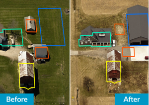
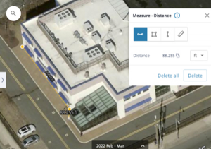
EagleView cloud will now include 1-inch ground sample distance (GSD) aerial imagery. The oblique imagery, usually captured at a 40°- 45° angle, provides enhanced clarity and side-angle views of buildings, homes and properties, enabling government users to view property changes and analyze roads and infrastructure to produce accurate tax assessments.
The company has also added 3-inch GSD orthogonal imagery to the platform. The orthogonal images help government users identify structural changes to buildings, additions to homes, and the condition of impervious surfaces. The images offer a top-down view and can be delivered annually or multiple times per year.
Next, EagleView Cloud aims to be available in commercial industries including insurance, construction and solar.
SandboxAQ has been awarded a Direct-to-Phase-II Small Business Innovation Research contract by the United States Air Force. SandboxAQ will test and evaluate its quantum sensor prototype to help protect military navigation resilience.
Under the contract, SandboxAQ will advance research and development for its quantum navigation system, which is being designed to complement GPS. It will be used for accurate navigation in contested or denied environments where the loss of precision GPS may negatively impact operations.
SandboxAQ’s AQ-powered quantum sensor prototype will be optimized in close coordination with USAF through identified innovation areas, including live demonstrations aboard USAF aircraft. The sensor prototype also has potential for use in the commercial sector for aviation, unmanned vehicles and more.
ADVA and Brandywine Communications have partnered to provide a defense-grade M-code device with advanced timing, the OSA 5422 grandmaster clock, for military applications. ADVA’s OSA 5422 meets key requirements of military networks by providing advanced positioning, navigation and timing (PNT) capabilities and improved resilience.
ADVA’s OSA 5422 grandmaster clock is integrated with a highly reliable M-code receiver, which meets stringent frequency and phase synchronization needs. The device is equipped with multi-band, multi-constellation GNSS receivers for when M-code is not available. OSA 5422 also has long holdover and precision time protocol backup, which enables it to maintain accurate timing even in the event of M-code disruption.
The OSA 5422 supports legacy interfaces such as BITS and IRIG and features eight field-upgradable 10G bit/s ports and 1G bit/s interfaces. The device is suitable for most demanding military edge applications.
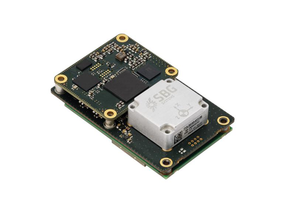
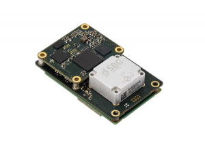
SBG Systems has released Quanta Plus, a GNSS-aided inertial navigation system (INS). Quanta Plus is a small, lightweight product, which can be easily integrated into survey systems with lidar or other third-party sensors.
The device combines a micro-electromechanical (MEMS) inertial measurement unit (IMU) with a resilient GNSS receiver to get reliable position and attitude, providing real-time kinematic (RTK) fixes.
Quanta Plus includes motion profiles, which enable users to optimize the sensor parameters to suit different use cases. The built-in precise time protocol server ensures sub-microsecond synchronization with external devices such as lidar. The device also has a built-in datalogger, Ethernet interface for easy integration, and a web configuration interface for simple setup and control.
The INS can be integrated with Qinertia, SBG System’s post-processing software. Qinertia improves the performance of acquired data during a mission using reliable RTK corrections from a wide range of continuously operating reference station networks, or by importing base-station data during the process.
Quanta Plus also improves the accuracy of the position and attitude using forward and backward processing and by integrating a tight coupling between GNSS and IMU data.
Quanta Plus is suitable for survey professionals or a navigation-dependent company seeking a robust navigation device. Specific solutions are available for integrators and OEMs who want to use Qinertia as a component in their application-specific data-processing solutions.
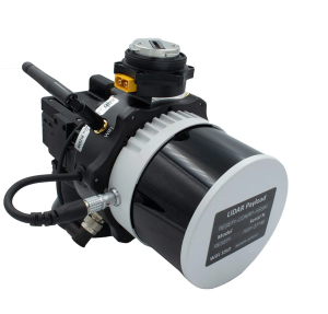
Inertial Labs has released a remote sensing payload instrument. The Resepi Hesai XT32 laser is designed for accurate remote-sensing applications. The Resepi laser can be used with commercially available lidar scanners, including Velodyne, Quanergy, Ouster, RIEGL, LIVOX and Hesai, as well as with UAVs.
Resepi is completely modular, so users have full control for customization. The remote sensing device uses a GPS-aided inertial navigation system with NovAtel RTK/PPK single- or dual-antenna GNSS receiver, integrated with a Linux-based processing platform. It also comes with a 2 TB USB memory drive and has an embedded Wi-Fi cellular modem.
Resepi has 3-5 cm point-cloud accuracy and can reach heights of more than 200 m above ground level. It is compatible with most UAV models; however, it is typically used with DJI M300, DJI M210 or DJI M600 models.
The device is suitable for scanning and mapping, precision agriculture with lidar, simultaneous localization and mapping (SLAM) algorithm development, utility inspection and construction site monitoring. Resepi-supported software includes Hexagon NovAtel, PCPainter and PCMaster.
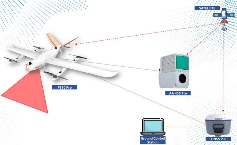
CHC Navigation’s mobile mapping solutions, the P330 Pro vertical take-off and landing unmanned autonomous vehicle (VTOL UAV) and the AlphaAir 450 lidar, are being used for mining exploration in Indonesia. The solutions help with effective data collection to measure the volume of an open-pit mine.
The P330 Pro UAV and the AlphaAir 450 provide an effective surveying solution, which is critical to the life cycle of mining projects. During this operation, the solutions covered more than 5 km² per mission, with an error of less than 5 cm. Accurate lidar in vegetated areas enabled surveying of the ground surface, including structures missed by other surveys due to dense vegetation.
A CHC Navigation i50 GNSS receiver and processing software provided with the AlphaAir 450 were deployed during the operation.
The P330 Pro UAV enables small- and large-scale aerial surveying. It comes with a portable ground control station for remote control and communication between the UAV and its operator. The UAV is designed for vertical takeoff and landing, making it convenient to operate and transport.
The AlphaAir 450 is a lightweight and rugged system, which integrates lidar with an industrial-grade professional 26 MP camera and an inertial navigation system for data collection.
UTStarcom has launched the SyncRing XGM30E precision time protocol (PTP) grandmaster. The SyncRing XGM30E is designed for mobile networks and other applications requiring accurate time and frequency synchronization. It is an addition to the company’s SyncRing line of network synchronization equipment.
The SyncRing XGM30E is an indoor PTP grandmaster offering echo time accuracy of more than ±40 ns, which can meet the stringent timing requirements of demanding applications including 4G and 5G networks. The clock complies with the PTP IEEE 1588-2008 standard, supporting major ITU-T frequency and phase and time profiles.
SyncRing XGM30E supports synchronous Ethernet (SyncE) output on all service interfaces for accurate frequency synchronization, and SyncE input for enhanced time holdover operation during GNSS outages.
The grandmaster includes an indoor rack-mount design and power supply redundancy with AC or DC built-in options and has flexible management options. The SyncRing XGM30E is available now.
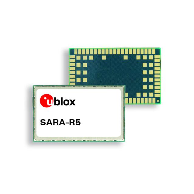
U-blox’s SARA-R5 series LTE-M module, based on the company’s low-power wide-area (LPWA) chipset, has been fully certified on all mobile network operators’ LTE-M networks in Japan. The module is the first u-blox internet of things (IoT) product to receive certification with all the Japanese operators.
The SARA-R5 series is 5G-ready and aimed at LPWA IoT applications such as industrial automation, sensor applications, connected health, metering, asset and vehicle tracing, and telematics. The module is also certified Microsoft Azure and qualified for IoT Core Amazon Web Services.
The SARA-R5 series has three product variants including the SARA-R500S-61B, the SARA-R510M8S-61B and the SARA-R510S-61B.
The SARA-R500S-61B offers standard LTE-M connectivity. The SARA-R510M8S-61B includes an integrated u-blox M8 GNSS receiver and a separate GNSS antenna interface, which provides reliable and accurate positioning data concurrent to LTE communication. This module is suitable for mobile applications such as automotive, fleet management and tracking, and telematics.
The SARA-R510S-61B is designed for low-battery powered applications including metering, security and surveillance, remote monitoring and more.
My previous column provided an update on the current set of published orthometric heights in the southeast Texas region and rules by the National Geodetic Survey (NGS) for estimating and publishing GNSS-derived orthometric heights using OPUS Projects. It also highlighted my personal crusade, that is the United States geodesy crisis. The Geodesy Crisis white paper can be downloaded from the American Association for Geodetic Surveyingwebsite.
This column focuses on potential errors in orthometric heights using a digital barcode leveling system with multi-piece leveling rods. Every business makes decisions based on expenses and ultimately on the profit margin. That said, making a business decision that results in a bad technical outcome may lead to issues that cost the company more than expected.
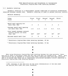
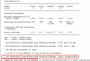
I have been involved with establishing orthometric heights, both leveling-derived heights and GNSS-derived heights, for most of my career. On a personal note, the digital bar code leveling system is important to me because I was the lead author of the document by the Federal Geodetic Control Subcommittee (FGCS) to incorporate the digital barcode leveling systems “Specifications and Procedures to Incorporate Electronic/Digital Barcode Leveling Systems (2004).” Recently, a colleague brought to my attention that many surveyors are using the digital barcode leveling system (which wasn’t a surprise to me), but they are not using the one-piece, single-scale, invar rod. They are using the multi-piece rods, either fiberglass or wooden. Surveyors can use any type of instrument to perform their project, but it will not meet the Federal Geodetic Control Subcommittee specification and procedures for leveling unless they use a one-piece leveling staff. This not a new requirement; it has been a requirement since the first publication of the FGCS specifications and procedures. Surveyors have always requested to use multi-piece rods but the potential errors associated with them were considered too large to be incorporated into the specifications and procedures to meet first-, second-, or third-order U.S. federal accuracy standards.
Excerpt from FGCS Specifications and Procedures (Image:FGDC)Excerpt from FGCS Specifications and Procedures (Image:FGDC)
In 2018, NGS documented a study to evaluate the use of multi-piece rods using the digital barcode leveling system. I first saw a draft of this report in 2011 and forgot that it existed. A colleague of mine recently provided me with the 2018 report. In my opinion, anyone who uses the digital barcode system and multi-piece rods should read this report and, of course, the rest of this column.
NOAA Technical Memorandum NOS NGS 75. (Image: NGS)
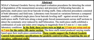
The image below provides the important summaries of the tests. I highlighted the statement “In the field, these errors were as high as 1.5 mm per setup and up to 7 mm for the entire 180-meter section.” In my opinion, an error of 7 mm in a 180-meter section is too large for any order and class of leveling. Also, the results of the study support the current FGCS specifications and procedures requirement of the use of one-piece, calibrated rods.
Image: NGS
The 2018 report states that multi-piece level staffs are popular among the surveying community because of their ability to break down into an easily transportable unit and they are relatively inexpensive and readily available. They may also be extended to reduce the number of leveling setups required over sloping terrain. This makes good business sense but surveyors should not make technical decisions based solely on business costs. That said, the FGCS “Specifications and Procedures to Incorporate Electronic/Digital Barcode Leveling Systems (2004)” prohibit the use of multi-piece rods for any order/class of leveling based on technical decisions, not on business expenses. To evaluate the multi-piece barcode rods, NGS developed and implemented laboratory and field tests designed to detect and quantify possible loss of precision in multi-piece leveling staffs. All their tests were conducted at the NGS Testing & Training Center located in Woodford, Virginia, in December 2011. The report was published in 2018.
The report did note that only a small sampling of instrumentation, three multi-piece leveling staffs comprising two separate models from two separate manufacturers, were included in the NGS study. Therefore, the results found within the report evaluate the accuracy and precision of the specific staffs tested. As the report states: “The tests are qualitative in nature with respect to bifurcation and non-Invar construction. Similar results are expected for similarly designed level staffs; nevertheless, the results should not be considered precisely valid for all types or models of multi-piece leveling staffs.”
Users should download the document and read it but I’ll highlight a few results. First, the report made the following statements about the plumbing of the rods:
“With the Leica GKNL4M level staff carefully plumbed, the section directly above the bottom section housing the level vial was visually slightly out of plumb. No correction was made for this effect in the lab or field tests. No measurements were made to the top third section of this level staff during this evaluation.”
“With the Trimble LD23 level staff carefully plumbed, the sections directly above and below the middle section housing the level vial was visually bowed and slightly out of plumb. No correction was made for this effect in the lab or field tests.”
Obviously, having a correctly plumbed rod is extremely important.
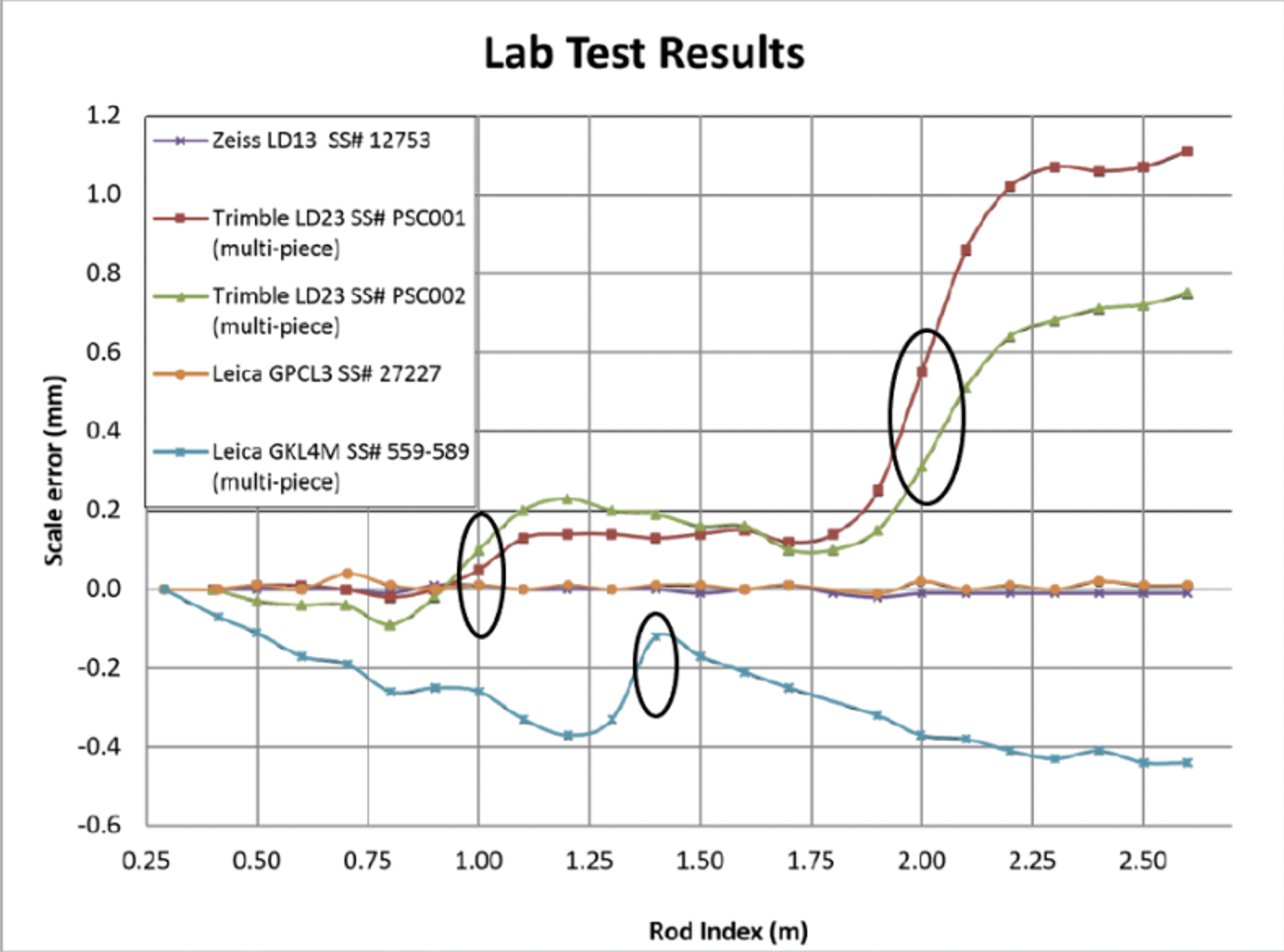
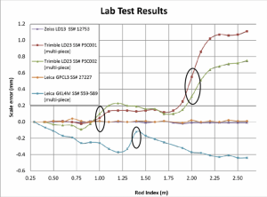
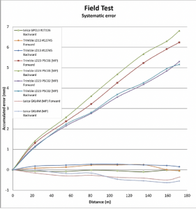
To estimate the potential scale error in a controlled environment, NGS performed a special test where they set up the level instrument 5 m from the leveling rods inside their building and made a measurement every decimeter on each rod. To perform this, the level instrument was moved upward one-decimeter after each measurement and the measurement was repeated. Figure 9 from the 2018 report depicts the results of the process. The first thing to notice is that the two calibrated, invar rods indicate very small errors. The other thing to notice is that there is a change in scale error at the section breaks of the multi-piece staffs. I highlighted the section breaks in the image below. The plots in Figure 9 indicate that the upper section of the rod is different from the lower section. This may result in a large error when going up (or down) an incline; that is, when leveling up an incline the upper section of a rod would be read in the back-sight reading and the lower section of a rod would be read in the foresight reading. The opposite would occur going down the incline.
Figure 9 from NGS 2018 report. (Image:NGS)
NGS also performed a small field test. The height difference was only 10 m over about 180 m distance. Figure 15 from the report provides the results of their field test. Some of the rods showed an error of almost 7 mm in the 180-meter section. Obviously, this is a significant error over such a short leveling distance, especially since it appears to be systematic. The report made a note about the systematic error; it noted that the height differences between the forward and backward runs were similar, but they were different from the standard. In other words, the forward and backward runs may meet a FGCS section misclosure but the mean difference would still have the accumulated systematic error. This means that following double-run procedures will not account for the systematic error. As a side note, according to FGCS specifications and guidelines, for establishing a height of a new bench mark, double-run procedures must be used. Single-run methods can be used to re-level existing work provided the new work meets the allowable section misclosure.
Figure 15 from NGS 2018 Report. (Image:NGS)
As stated in the 2018 report, errors as large as 6.8 mm over a 180-meter sloping section were due to using the multi-piece leveling rods. This is unacceptable for meeting FGDC specifications and procedures for leveling surveys.
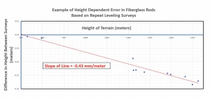
The NGS report was based on a small sample and over a very small project area. It provides a compelling argument for requiring one-piece leveling rods. Now, for a real-world example that supports the results of NGS’s study. I received a report where the results of repeat leveling surveys using the multi-piece fiberglass rods over the same basic route indicated a large systematic height error. The figure below provides the difference in heights between the two surveys. As indicated in the figure, the data indicates a height dependent error of -0.43 mm/meter between the two surveys. In this example, the difference approaches 200 mm. Clearly this type of systematic error needs to be accounted for when multi-piece barcode rods are used in a survey.
Example of Height Dependent Error in Fiberglass Rods. (Image: Dave Zilkowski)
As previously stated in the conclusion of NGS’s 2018 report, “Calibration of these type survey instruments provides a means of quantifying these type error sources, thus providing a mechanism for ‘correcting’ for them during post processing of data sets.” If a company or agency created a calibration process similar to NGS’s test site, then surveyors could use the site to evaluate their multi-piece barcode rods. In my opinion, until users account for the index and scale error in multi-piece barcode leveling rods, they should not be used to perform leveling surveys to compute orthometric heights with any expected accuracy value.
Clearly, it is more cost effective to use multi-piece rods instead of single-piece invar rods because of the increase in expenses for the single-piece invar rods. However, making a business decision that results in a bad technical outcome could lead to lawsuits, professional liability issues, and/or additional expenses for having to resurvey projects. Enough said.
Slingshot Aerospace has awarded to Hawkeye 360 a radio frequency (RF) data provider contract for monitoring GPS interference. Hawkeye 360 will provide data for Slingshot’s space-based monitoring and detection of RF threats and support its Proliferated Low-Earth Orbit (pLEO) Data Exploitation and Enhanced Processing (DEEP) program for the United States Space Force’s Space Systems Command (SSC).
The partnership between Hawkeye 360 and Slingshot will make it possible to capture, process and characterize the RF signal environment into timely insights for U.S. government space operators.
Hawkeye 360’s data will support developmental and operational test events, which will ultimately provide information on how to detect early signs of illegal RF activity. The support and capabilities the companies are providing enables the U.S. Space Force to prevent and combat electronic warfare and discover early signs of GPS interference.
The Open Geospatial Consortium (OGC) is calling for participants in Disaster Pilot 2023, which aims to reduce disaster preparation time and accelerate transforming data into decisions. All responses are due by Feb. 17.
Disaster Pilot 2023 aims to enable key decision makers and responders to discover, manage, access, share and exploit location-based information to support disaster preparedness and response. The focus of this year’s pilot is to update the OCG Disaster Readiness Guides on flooding and landslides to include information on wildfires and droughts.
The pilot provides the opportunity for participants to collaborate with a range of disaster stakeholders, including Earth observation data providers, relief organizations and field responders. The goal of the pilot is to help shape the future of disaster management systems through user-centric interoperability arrangements, identification of critical data sharing challenges, and the delivery of cloud computing scale and agility to field personnel and relief organizations.
The Disaster Pilot 2023 is being conducted under OGC’s Collaborative Solutions and Innovation Program.
A Q&A session is available on Feb. 1 for interested participants. For more information, visit the Disaster Pilot 2023 page.