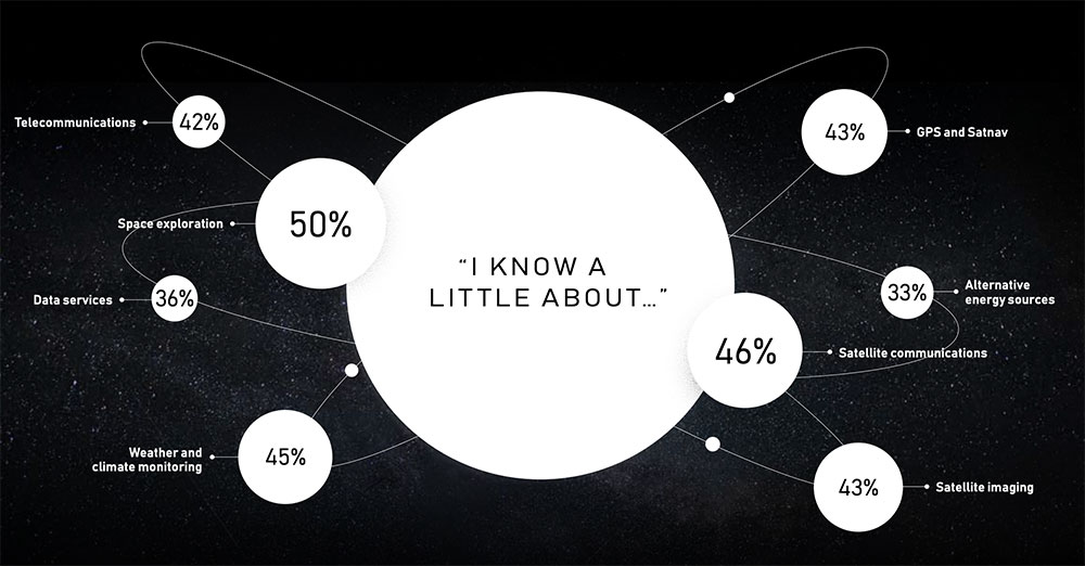
The satellite company spoke to 20,000 people in 11 countries across the globe to uncover their perceptions of space, what happens “up there” and how they think it impacts life here on Earth.
The survey found that most people have no idea about the benefits of space. Only one third are excited about space, with 47% concerned about space junk and just 8% associating space with communications and connectivity.
Just 8% of respondents associate space with communications and connectivity.
“From connecting rural communities to helping solve climate change, we know the enormous potential space holds to improve life on Earth, and what it has already brought us,” Inmarsat said in a statement. “Now, both the magnificent possibilities and the potential risks of space, which Inmarsat is working hard to address, need to be showcased to the world.”
The report also features contributions from renowned figures in the sector including Scott Kelly, former astronaut and commander of the International Space Station, and Josef Aschbacher, director general of the European Space Agency.
“The research findings mark a real wake-up call for the space industry,” Inmarsat said. “It’s clear that people have a low understanding of the breadth and richness of the work being done in space today. Perhaps because the technology deployed is essentially invisible, people do not appear to understand the role space is already playing in their everyday lives, nor its potential to deliver a brighter future for our planet.”
ComNav Technology now provides a GNSS high-precision positioning solution for navigation and positioning of autonomous lawn mowers. Environmentally friendly and intelligent robotic lawn mowers are growing more popular, making the mowing task easier, safer and more convenient.
R&D background
It is difficult to develop autonomous lawn mowers because they obtain navigation information by means of visual and acoustic sensors, usually through embedded cables in the working area and detection through eddy current sensors. The shortcomings are obvious: before the mower starts, it must be set up with cables and other equipment. Cable requirements differ in various countries, and cable laying can be complicated, wasting resources and money.
With these difficulties in mind, ComNav applied its K8 series of GNSS high-precision modules to lawn mowers to break through the application limit. It solved this accuracy problem to make the lawn mower achieve centimeter-level driving according to the setup path in an open field. With ComNav’s other technologies — quantum algorithm and LAI, HighLock, PPP, RTK-KEEP — the law mowers continues to operate under trees, around corners or in other obscured areas.
Introduction of ComNav’s solution
With the K8 series module, ComNav facilitates the lawn mower’s fieldwork with position data provided by GPS, GLONASS, Galileo, Beidou, QZSS, IRNSS and SBAS.
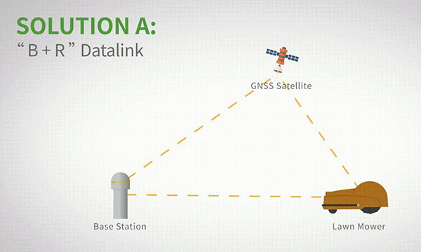
The high-precision positioning system for lawn mowers consists of a base station and a rover station. Three solutions are recommended for the terminal to obtain differential data from the base station.
Base and rover datalink. A base station acquires differential data through a datalink and provides corrections to the rover. The rover station — comprising the parts installed on the lawn mower, including the GNSS antenna, the GNSS high-precision module, datalink and UHF antenna — enables centimeter-level positioning and navigation.
Image: ComNav
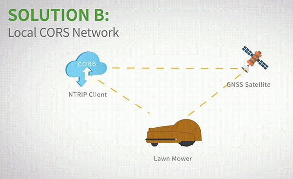
Local CORS network. Utilizing existed local CORS, the rover station obtains differential data from the CORS service, enabling the lawn mower to achieve positioning and navigation accuracy on a centimeter level.
Image: ComNav
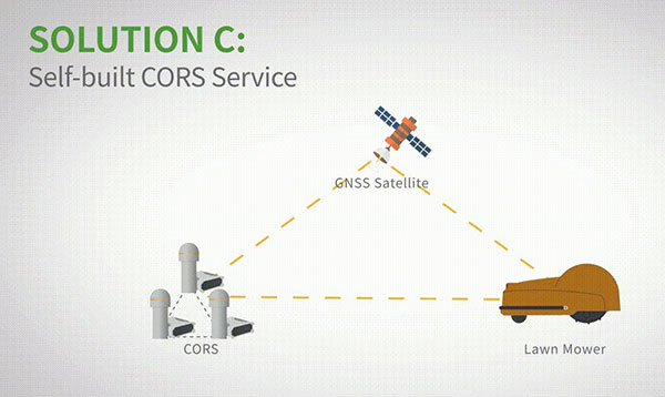
Self-built CORS network. Base stations can be placed anywhere based on requirements. Doing so eliminates the worry about prevailing conditions and makes high-precision positioning and navigation of lawn mowers possible.
Image: ComNav
Technology Features
LAI technology. ComNav’s patented low-power anti-interference (LAI) technology provides a jamming-to-signal ratio of up to 50 dB. Power consumption is only 0.1 W when turned on. By quickly detecting and eliminating interference with simple settings, LAI technology can reduce failure time and ensure safe operation. The technology can generate a spectrum diagram of interference sources, enabling identification of interference types and potential interference sources.
Quantum algorithm. ComNav’s quantum algorithm has sophisticated technology for detecting and repairing cycle slips. It uses full-constellation and full-frequency tracking capabilities along with multi-frequency combination, model and parameter estimation. Quantum is able to eliminate errors caused by the ionosphere, the troposphere and multipath in seconds. As a result, the initialization time of real-time kinematic (RTK) is greatly shortened and precision and reliability are improved. Meanwhile, the extra-long baseline calculation capability expands the operation range.
RTK-KEEP technology. By estimating model and parameter values, RTK-KEEP Technology can reduce errors caused by satellite orbit, clock difference, ionosphere and troposphere when the base station’s data is lost. Centimeter-level accuracy can be kept for more than 10 minutes, greatly improving the availability of RTK.
Benefits of ComNav’s Solution
ComNav’s solution allows the lawn mower to achieve centimeter-level positioning and reduce mowing repetitions. It helps the lawnmower to operate safely and reliably in the corners, under trees, or in other places where satellite signals are weak or lost. With its strong anti-interference capabilities, the lawn mower can maintain continuous and effective positioning in complex environments, meeting the needs of a variety of applications.
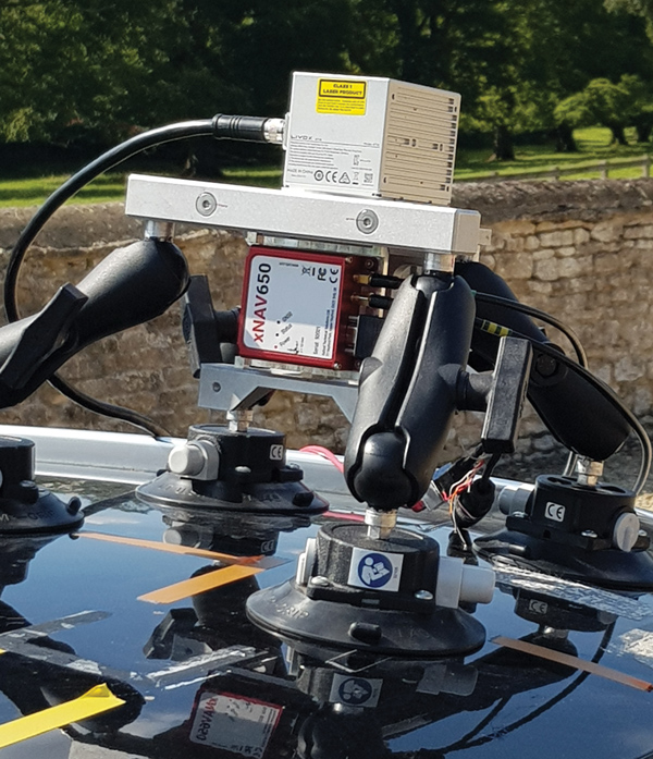
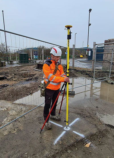
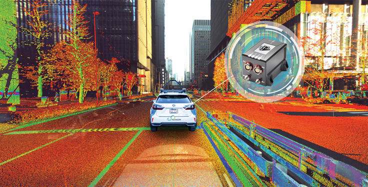
Mobile mapping using an OxTS xNAV650 INS and lidar sensor. Photo: OxTS
We discussed mobile mapping with Jacob Amacker, application engineer, OxTS.
How do you define “mobile mapping” as opposed to “surveying”?
We use the two terms interchangeably. Each one has a different connotation depending on where you are in the world and both can be useful. We use them to cover a broad range of use cases, but “mobile mapping” is used more specifically for land-based mapping of the environment. A typical application might be a van equipped with an INS [inertial navigation system] and lidar sensors.
“Surveying” can be used a bit more generally, applying to aerial or pedestrian-based mapping, but it does have the connotation of static mapping, which we do not typically handle.
What are your main markets for mobile mapping?
It is very hard to say. The world of mobile mapping is so diverse. However, lidar mapping could be seen as both the largest and the fastest-growing market in the surveying world as lidar has become widely affordable. Although our technology can be used with any surveying devices, at OxTS we particularly like to use lidar and are focusing on getting the best results from lidar data. This has included making our own point-cloud georeferencing software to maximize the potential of our navigation data in making point clouds.
What are the main differences between your devices for aerial mapping and for ground-based mapping?
We use the same INS device for both ground and aerial mapping. For use on manned aircraft, we would always recommend our highest accuracy system with the best IMU, the Survey+. The main source of inaccuracy in survey data will come from the IMU error over the range to the objects. Because most of this range is the aircraft’s altitude, this error is quite significant. For land-based mapping work, the measurements provided by the lighter and smaller xNAV650 are still suitable for many high-precision applications.
GNSS-INS integration has been done for decades. What is new and what are the remaining challenges?
It is now much more affordable to have very high-grade IMUs and GNSS receivers. Nevertheless, there will always be further improvements to be made to how the data streams are combined. On a similar note, other navigation aiding sources are increasingly being considered to supplement the IMU and the GNSS receiver — such as wheel speed sensors, lidar, camera odometry and others that can also be integrated to stabilize and improve the navigation data. Overall, it is very exciting what is yet to come out of INS technology. In recent years, it has become so good that people expect more and more from it, and this demand must be met. What happens when GNSS drops out? We are seeing increasing development to make the navigation data robust against challenges of any environment.
Given the IMU’s drift, for how long can your system function at an acceptable level in case of a GNSS outage?
It is difficult to put a number on what kind of drift is acceptable, as it depends on the application and the end-user requirements. Typically, half a meter of drift in one minute of GNSS-outage might be the goal for some of the higher-grade surveyors. Still others might only be satisfied with negligible drift.
What keeps the INS and the lidar unit synchronized during a GNSS outage?
The INS has an internal clock to keep the timing during a GNSS outage. Of course, this will not be as accurate as the atomic clocks on the satellites, but it is quite adequate to maintain survey-grade accuracy during GNSS outages. GNSS is still necessary to get the timing information in the first place, and this is a reliance that INS devices will want to remove in the future.
What are the key remaining technical challenges in UAV lidar mapping?
With continuing improvements in UAVs, lidars, GNSS receivers and other sensors, the key to unlocking more efficiency and profitability in this market will be improving and simplifying workflows and processing. The next frontier is integrating AI and machine learning with digital twin models to create forecasting tools.
UAVs are much cheaper to operate than manned aircraft per hour, but not necessarily per square mile. UAVs can cover ground that cannot be mapped from a land vehicle; however, the latter have a much greater range.
You are correct. Each type of vehicle has its area of best utilization. Once we know what the customer wants from the data being collected, we can determine the size, weight and power (SWAP) of the payload needed, and then it’s a matter of analyzing cost versus capability and working with the customer to pick the right payload for the right vehicle at the right price.
What positional accuracy do you achieve for your point clouds?
With our GNSS-receiver-based navigation unit, which also includes an IMU and key IP [intellectual property] from our company, and the right combination of tools, we achieve an accuracy of 2 cm to 3 cm.
What are your key markets for UAV lidar mapping?
I believe it is still the Wild West in this market space. Really smart people are figuring out new ways to use these systems every day. We sell systems to teams doing high-end inspections of infrastructure, such as roads, bridges, corridors and power lines, as well as for land surveying and mining.
What was a recent application of one of your mapping systems?
One of our most recent success stories has been the launch of our Geo-ECTO-1 system. It features dual lidar sensors combined with a 360-degree FOV [field of view] camera and high-end GNSS receiver. It is ruggedized from the ground up and is meant for high-end survey and infrastructure inspection work. The payload is designed to quickly transition to a UAV-based system. Our two launch customers/partners are California-based survey companies Guida Survey and LACO Survey. It has been a great experience getting these systems up and running with our partners.
Our next adventure will be to work with UC San Diego’s Scripps Oceanographic Institute. We are proposing and demonstrating one of these systems to be used for analyzing cliff erosion on the beaches here in California, where several collapses have led to the loss of life. We want to support figuring out how to use the analyses to create a system that would give early warning of trouble spots. With these tools we can make our beaches much safer.
In 2020, OCP-TAP started working on highly precise and hyper-scalable time synchronization services in its data center market, using a GNSS clock source and precision time protocol (PTP) technologies. OCP-TAP technology adds scalability and improves the accuracy of timekeeping within the infrastructure industry.
In 2021, OCP-TAP integrated its technology into the time card and introduced it as an open-source solution to build time servers.
The Protempis Res720 embedded module provides a highly accurate GNSS clock source to further increase the accuracy, resiliency and adoption of the OCP-TAP’s new time card duo, which was announced in an OCP Tech Talk on June 2.
OCP-TAP provides a new collaborative community focused on designing hardware and software to efficiently support critical timing accuracy and resiliency demands on computer network infrastructure.
Protempis Res720
Protempis’s Res720 embedded module adds a dual-band GNSS time reference to the time card to improve resilience, noise rejection and anti-spoofing and anti-jamming capabilities.
The Res720 GNSS embedded timing module is suitable for data centers, 5G Open RAN and XHaul, smart grids, industrial automation and SATCOM networks. It provides 5 ns timing accuracy, dual-band GNSS support and anti-jamming/anti-spoofing capabilities.
The Res720 embedded module provides unparalleled performance as a timing source in embedded systems, including to time servers, network interface cards, radio units and routing/switching devices for 5G, private wireless, Open RAN and data networks.
“Protempis brings its expertise in GNSS and network synchronization to Meta, the OCP-TAP, and the open-sourced time card. Their highly accurate dual-band GNSS product has shown how it can improve operations,” said Ahmad Byagowi. Byagowi is inventor of the Time Card, founder and project lead for OCP-TAP, and a research scientist at Meta.
“We are honored that our Res720 dual-band technology will be used for enabling time-sensitive applications over OCP-compliant and PTP-aware networks,” said Karen Guldan, Protempis president. “We look forward to a continuing partnership with OCP-TAP and global network leaders working to advance solutions to provide ongoing timing accuracy and resilience.”
Precisional, an affiliate of The Jordan Company (“TJC”), announced May 9 that it completed the previously announced transaction to acquire four industrial technology businesses from Trimble, including Protempis (formerly Trimble Time and Frequency).
Skydel 22.5 features advanced hardware-in-the-loop testing
Orolia has released Skydel 22.5, a significant software upgrade to its Skydel simulation product line that features advanced hardware-in-the-loop (HIL) testing solutions providing very low to zero effective latency.
The enhanced visualization tools can monitor internal latency through real-time curves showing when the data is generated and sent to the RF signal. Users can also review the transmission of HIL packets for optimizing the entire network’s latency, checking its stability (jitter), and that data is available and used at the right time in Skydel.
HIL testing is an essential step in the verification process of the model-based design (MBD) approach because it involves all the hardware and software that will be used operationally. HIL verification can test a standalone device-under-test (DUT) or, more generally, an entire complex system consisting of multiple DUTs in both open- and closed-loop architectures.
“The vast majority of problems encountered by engineers on HIL systems are related to poor control of the latency of the entire simulation chain, as they are insufficiently accessible, transparent and controlled on the competing systems,” said Pierre-Marie Le Veel, principal system architect and product manager for GNSS simulation. “Thanks to these tools, our high-end performance and well-known intuitive automation, Skydel dramatically reduces the implementation time of a HIL system (which can be very significant) and, therefore, the project’s overall cost.”
Photo: Orolia
In addition to these tools, Skydel implements modern extrapolation algorithms that achieve zero effective latency. These algorithms make it possible to keep position errors negligible, even for equipment with very high dynamics used in national defense applications such as missiles, rockets and guided shells.
“These advanced HIL algorithms and tools are available – and with the same performance – on our Wavefront simulation systems to test controlled reception pattern antenna (CRPA) systems,” Le Veel added.
Additional constellations, signal types and options such as real-time kinematic (RTK) and multi-instance are available along with dedicated bundled simulation starter packages for automotive.
The upgrade is available at no additional cost for existing users operating Skydel 22.5. Application notes, support documents and tutorials are available online.
The Boston Dynamics Spot robot equipped with Velodyne lidar. (Photo: Velodyne)
Velodyne Lidar Inc. has signed a multi-year agreement for its lidar sensors with Boston Dynamics, a mobile robotics company best known for its “Spot” dog-like robot.
Boston Dynamics selected Velodyne’s sensors to provide perception and navigation capabilities for its highly mobile robots. The sensors enable mobile robots to operate autonomously and safely, without human intervention. They provide real-time 3D perception data for localization, mapping, object classification and object tracking.
Velodyne’s power-efficient sensors support autonomous mobile robots in a wide range of challenging indoor and outdoor environmental conditions, including varying temperature, lighting and precipitation, the company said.
Velodyne’s lidar sensors will enable the robots to autonomously navigate complex environments, safely avoiding obstacles and finding the fastest route to perform tasks in environments from manufacturing plants and construction sites to distribution centers and warehouses.
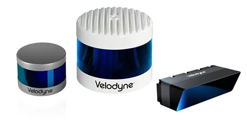
The Alpha Puck, Alpha Prime and Velarray M1600 lidar sensors. (Photo: Velodyne)
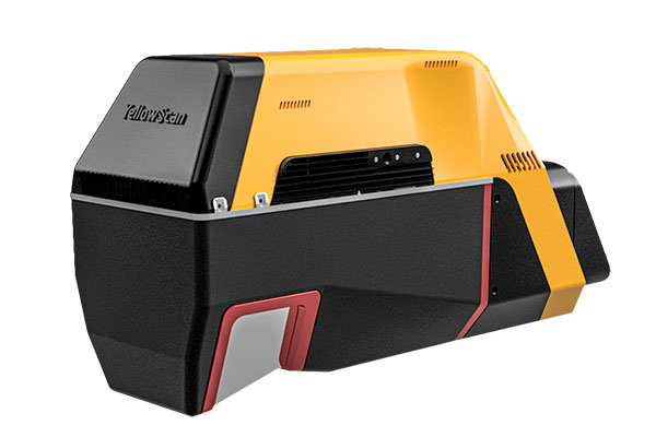
YellowScan has released a new long-range lidar scanner. Voyager is a powerful solution for both manned and unmanned aircraft.
With Voyager’s wide field of view, all of the points collected are oriented toward the ground, meaning there is no loss of points. This also means 1.5 million points per second will be usable, which would not be the case with a 360° scanner.
Voyager combines a Riegl VUX-120 laser scanner with a Trimble Applanix AP+ 50 AIR or Applanix AP+ 30 AIR GNSS-inertial board, providing precision of 0.5 cm and accuracy of 1 cm.
Voyager’s detection and processing of up to 15 target echoes per laser pulse allows for excellent vegetation penetration. Its has an extremely fast data-acquisition rate of up to 1800 kHz, suitable for projects requiring the highest point density.
The laser scanner’s specifications can be customized to fit the needs of various projects and platforms, and can be combined with YellowScan’s full suite of software solutions to easily extract, process, merge and colorize point-cloud data.
Business Model Enables Mass Adoption of Product with Service
In September 2021, Trimble released its DA2 GNSS receiver with Trimble Catalyst service. I asked Gareth Gibson, the company’s marketing director, Mapping & GIS Solutions, about the product and recent developments in GNSS-enabled mapping.
When I started in this business, more than 20 years ago, we used to divide GNSS receivers into three categories, broadly speaking: consumer grade, resource grade, and survey grade. Are those distinctions still useful?
The survey world and the mapping world have been coming together over the last 20 years or so. Probably Jack Dangermond was one of the first people to publicly acknowledge that. Surveying is an ancient profession whereas mapping and GIS, as an industry, has evolved much more recently. The techniques and the expectations of precision and the complexity of the workflow coming from the survey side has always been somewhat at odds with what the mapping world has been trying to achieve, so the products and the tools of these industries were quite different.
The Trimble DA2 receiver boosts the performance of the Trimble Catalyst GNSS positioning service. (Photo: DroneWorks)
However, there has been a blurring of the lines. Today, the capabilities of mapping-grade GNSS systems are no different from those that can be used in the survey industry as well. Catalyst is an example of that. However, the focus is much more on ensuring that the technology gets out of the way. Let the technology vendor take care of the hard parts, to make it work in the environments where it needs to work, and to make sure it operates with the software that allows the mapping user to focus on the job, with less complexity. We’ve reached that point where it’s difficult to distinguish the capabilities of a survey-grade receiver from those of a mapping-grade receiver. Technically, there’s very little difference.
You can think of Catalyst as renting the performance of the receiver to enable the work to get done. The convergence of technology is enabling the business model transformation, and the business model transformation is aiming to better address the needs of the user. The types of services that these tools enable, the methods with which these tools communicate with homebase and with the vendors—licensing systems, platforms and so forth—have reached a point of enabling delivery of products as a service. That is a good thing because customers are not interested in owning a product as much as they are in getting to the solution that they need.
So, the focus switches from “How do we deliver this product?” to “How do we best deliver this service and the solution?” Catalyst attempts to do that by delivering, in effect, positioning as a service. You are not buying a piece of hardware; you are purchasing the capability to generate and use high accuracy within your workflow to get your job done. That shifts the focus from upfront expense to delivering positioning as an operational cost.
What does the DA2 with Trimble Catalyst service enable that was not previously possible?
It enables the mass deployment of precise GNSS across organizations with tens or hundreds or even thousands of workers. They can now benefit from adding GNSS technology to their work where it was previously prohibitively expensive, too complicated, or simply incompatible with their workflows. Catalyst and the DA2 is enabling that through the business model, which we have employed for the technology, and through the technical capabilities of the platform, which has reached a point of being much easier to be mass adopted across organizations.
The significant change that we’ve made with the DA2 was the addition of support for Apple-based devices. The norm now is to use the phone or the tablet that you have in your pocket, as opposed to purchasing dedicated equipment, especially as it relates to the group of workers we would describe as the location-enabled workforce. These are people typically who are not trained surveyors or GIS professionals but are performing a function with an organization and location-enabled workflows. Software applications are just part of their toolkit for their day-to-day work. It does not make sense to equip these teams with very expensive and complicated equipment, but the functionality that the equipment can provide can unlock some areas of productivity that would have otherwise been inaccessible to them.
What are the remaining technical challenges to mapping for GIS and asset management applications?
The nut that we’ve cracked is enabling precision at almost any practical level, using GNSS, anywhere around the world. We continue to strive towards having access to that level of precision in any environment. There’s a limit to what can be achieved with GNSS alone. So, we start to see more and more the use of combined technologies, different data and sensor fusion. People are leveraging different parts of the technology jigsaw — what is available on their phones, what is available from external sensors, and what they can do with the raw data they are capturing, either directly within a piece of software on their mobile device or somewhere in the cloud, to make better use of the raw information that has been captured.
The second major area is the merging and connecting of workflows, not just the types of data that these organizations are capturing. Organizations are working with field teams, all that data coming together and being able to be used in a toolbox to enable different types of work to get done. In the past, things have been a lot more siloed. Now, technology is enabling us to work together in more clever ways. It is easier to share information.
“The nut we’ve cracked is enabling precision at almost any practical level, using GNSS, anywhere around the world.”
Is accuracy the only difference between surveying and mapping?
For surveyors, the primary deliverable is location. The historical basis of that industry is all about being able to capture and work with information in the most precise way possible. In the mapping world the focus is more on the information that’s being captured about that position, and its precision is just another attribute. That has helped to change our perspective on the relative importance of precision as part of the workflow and has driven us more towards trying to simplify the way that location is captured in a mapping workflow.
Our goal is to capture the most accurate position and to simplify the process for the user. We’ve tried to automate such things as the choice of correction service so that it’s a much more approachable technology and the user can focus on their area of expertise, which is the collection and designation of the mapping attributes.
What are the components of the Trimble Catalyst solution?
There are two elements to Catalyst. One is positioning as a service, enabled through a subscription. The other is the GNSS antenna. The latest generation of that is the DA2. We have made some changes to the DA2 to enable some better functionality and broader applicability. Without a high-quality antenna, there’s only so much that you can do with GNSS. Our focus with DA2 was to make the antenna component of the solution as small and lightweight as possible, but as high performance as possible. We’ve enabled that through a combination of very clever engineering.
The physical structure of the antenna is quite different from that of any other antenna that we build within Trimble. The idea to make it simpler, lighter and lower cost influenced almost every design decision that went into how that antenna is built — from how it fits and mounts with varying carrying solutions to how it is powered. In the first version of Catalyst, we had this notion of running the GNSS receiver as software inside using a computer that was freely accessible and available to every user without needing to burden the antenna itself and create a smart antenna. We said, “Well, if we can deliver GNSS by software, let’s leverage the computing power of the user’s phone or tablet.” So, we took the Catalyst GNSS receiver engine and ran it as an app on a phone.
The Trimble DA2 receiver at work. (Photo: Trimble)
There were some limitations with that approach. We needed to have a fully cabled solution between the antenna and the phone to enable the required bandwidth from the antenna to the software itself, which required a USB connection and put a fairly heavy computational burden on the phone. However, that enabled us to strip out a lot of the excess weight and complexity from the antenna design, which lowered the cost of the antenna. It was a trade-off decision.
With the DA2 we’re acknowledging those changes, plus the limitations that are imposed by wanting to be compatible with the Apple environment of devices. We can still create a very low cost and lightweight computing package to run this same engine in software, but just move that computing resource back into the antenna again. So, it’s still a software defined receiver—effectively a completely different technology from what you would find on a typical hardware receiver.
We have added a wireless radio to allow GNSS positions to be communicated back to your phone or your tablet via Bluetooth. So, DA2 is a lot more versatile because it enables iOS device usage and wireless transfer information from the antenna to the phone or tablet.
Now, how do you make that work as a package to deliver high-precision results? You need access to correction services and a definition of how you want the receiver to behave based on a business model of what consumers are charged. That’s where the subscription component of the Catalyst service comes in. With Catalyst, we want to simplify the way that customers choose what they want and how they get it.
So, rather than purchasing a specific hardware configuration, figuring out what correction services to use, and how to configure them, you simply subscribe to whatever your required performance level is, and Trimble handles the rest. Each subscription is time-based, so it could be annual, monthly, or even hourly. It is a completely managed system that works everywhere in the world.
What are the options for receiving the corrections?
The DA2 supports delivery of corrections over the internet or through the antenna itself — so, in an offline or an online environment. Catalyst uses Trimble’s dedicated correction services, so Trimble VRS Now, which is available in parts of North America and most of Western Europe, as well as Trimble RTX, which is available everywhere in the world and is also delivered by internet or by satellite L band. Globally or regionally available augmentation systems such as EGNOS and WAAS, and those smaller systems for DGPS-type positions, are also used where it’s necessary as a fallback option.
The receiver will choose what correction service it needs to use based on the user’s subscription level and the environment in which the receiver is currently operating. It knows where in the world it is and which license type the user has, so it will try to use the best available source without the user needing to really think about it. The user just specifies to which precision level they want to subscribe — such as one centimeter or 10 centimeters — and the receiver figures out the rest. Catalyst also supports those customers who have their own correction services and want to use it. In most cases, however, that’s not necessary.
Does the current version of Trimble Catalyst differ from the previous version in any other way?
With the latest generation of Catalyst you no longer need a high-end phone to run the service because we have removed the reliance on USB to deliver the data from the antenna to the controlling device. Now, you can effectively do all the computation in the antenna and use Bluetooth for data transfer, which makes it a bit more versatile. Additionally, we have introduced a handle that allows you to use the DA2 in a handheld format that also stores a battery pack.
The biggest leap was certainly the addition of iOS support. After releasing the DA1, we quickly realized that it was not addressing your needs if you were not an Android user it. In North America, more than 70% of business organizations prefer Apple to Android. So, this improvement has more than doubled our addressable customer base. It’s also for those mixed fleet organizations that did not adopt Catalyst because they did not want to have one solution for their Android users and a different one for their iOS users.
What markets and applications are you targeting with it?
We’ve been pleasantly surprised by the response to DA2 and the types of customers that we are seeing. We define our customers in four buckets. One consists of small, independent, non-geospatial businesses, which is a new area for us—the geospatially enabled workforce, people who are using applications that have a location component, who previously would not have been able to justify the purchase of dedicated and expensive equipment. In this bucket I would put landscape gardeners for example, or golf course designers or people who now can create a map much more easily and effectively.
Another consists of consultants and contractors. These are organizations small and large doing geospatial contract work. They are specialists who get sent out into the field to either do mass data collection projects or to consult and provide professional services with a geospatial bent. These are much more traditional customers; they know a little bit more about the technology and what they’re doing. For these customers, Catalyst is a new tool. It enables them to deploy GNSS more broadly across their organizations.
Then there are the sort of organizations and businesses that run their own teams and perhaps have their own GIS department and a field crew dedicated to operating and maintaining the GIS. But they also have the field operations groups, who aren’t geospatially savvy or aren’t geospatial professionals. They’re starting to deploy GNSS across their teams more effectively, as well, because Catalyst is the type of tool that you can keep in the glove box of your car and have available to use at a moment’s notice. So, utilities, municipalities, public works organizations and the like, large federal government agencies in the United States especially.
Finally, the owners of large infrastructure assets, privately owned organizations running ports or oil and gas operations. Again, this is an attractive solution for them. We’re finding that this solution will enable us to address the full range of the market much more effectively.
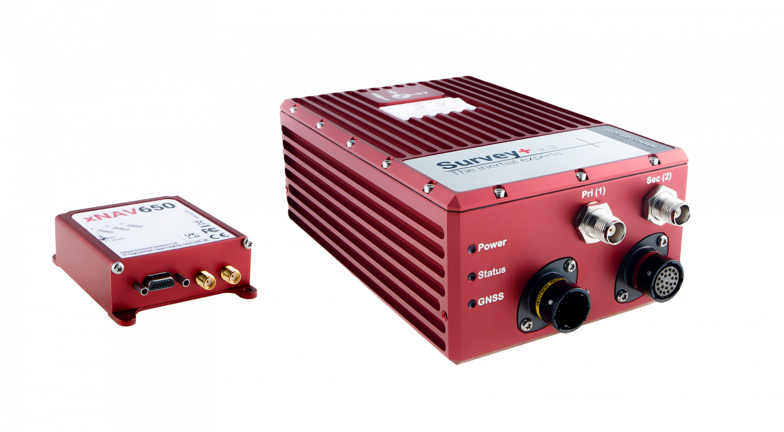
OxTS manufactures inertial navigation systems (INS) and proprietary software on which survey professionals have come to rely. Our devices, the Survey+ and the xNAV650, output highly accurate position, heading and pitch/roll measurements. An advanced navigation engine combines streams of data from onboard inertial measurement units (IMUs) and GNSS receivers. This data can then be used in a multitude of applications including lidar survey, mobile mapping and open road positioning.
Surveying, especially with a lidar sensor, can be a complicated art. There are many factors to consider even before you begin. However, system manufacturers involved in the survey industry, such as OxTS, are taking steps to simplify lidar survey.
The end goal for many lidar surveyors is to create an accurate point cloud. However, to produce the best possible results, the hardware and software involved must be working together in unison.
Hardware = lidar sensor and INS
Software = georeferencing, post-process and configuration
In this article, we have picked out a few of our favorite developments on the topic of simplifying lidar survey.
Research and Development
OxTS invests substantially in research and development to ensure that our hardware and software developments meet the ever-evolving demands of the survey industry. Many of the improvements generally center around improving accuracy, clarity of results and user experience. However, general industry demands also drive some development.
For example, the increasing use of drones in surveying has increased demand for smaller and lighter INS hardware. Whilst developing smaller and lighter hardware is therefore important it cannot be to the detriment of reliability and accuracy. The xNAV650 was born from this industry demand.
Although development of the xNAV650 was primarily driven by the needs of the survey industry (smaller/lighter hardware), other improvements OxTS has made to the software portfolio has focused on improving user experience.
xNAV650 and Survey+ inertial navigation systems. (Photo: OxTS)
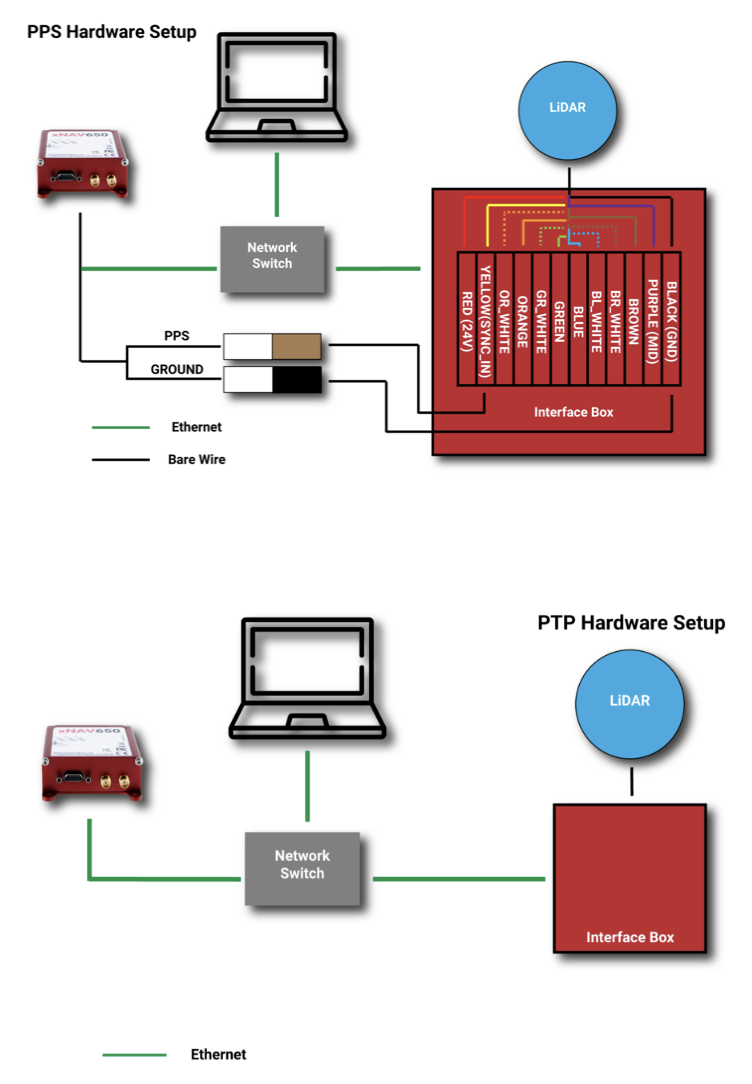
Precision Time Protocol (PTP)
One of the major advances in OxTS INS technology over the past 12 months is PTP. The drive to include PTP capability on all OxTS Survey INS devices was the intention to help surveyors simplify the lidar survey set-up process.
When using compatible lidar sensors, such as those from Hesai and Ouster with an OxTS INS, surveyors no longer need to build complex wiring solutions. A simple ethernet ‘plug-and-play’ process is all that is required.
The images below show a traditional PPS wiring set-up vs PTP:
A traditional PPS wiring set-up vs PTP. (Image: OxTS)
Software
To get the desired outcome, an accurate georeferenced point cloud, from any lidar survey in a timely manner the software must be simple and straightforward to use. As the saying goes “complexity is the enemy of execution,” and this is what drives software development at OxTS.
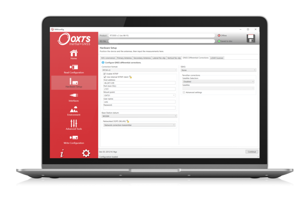
Once the lidar and INS are plugged in and ready to survey, configuration should be straightforward. A simple configuration wizard, such as the one available in NAVsuite (OxTS’ complimentary software toolbox) should structure the set-up process so that nothing is missed.
NAVconfig – OxTS’ INS configuration software. (Image: OxTS)
The latest NAVsuite update (version 3.3) included a new PTP graphical user interface (GUI) to simplify survey set-up even further.
Other tools are included within NAVsuite that allow users to analyze, troubleshoot and post-process their INS data. Read the NAVsuite for Survey and Mapping infosheet to find out more about these.
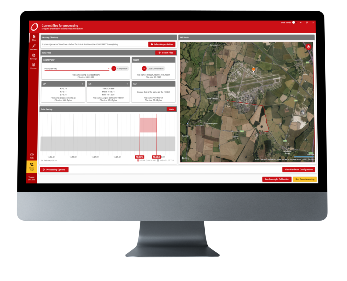
OxTS Georeferencer
OxTS Georeferencer. (Image: OxTS)
Since its launch approximately two years ago, OxTS Georeferencer has gone through some major changes. The first version included compatibility with the Velodyne VLP-16 lidar sensor. This meant that users of the VLP-16 had a quick and simple way to georeference the lidar data.
Over the course of the next 24 months, multiple new sensors have been introduced. Sensors from Hesai, Ouster, Livox and new Velodyne devices are now available, giving users more choice than ever before when it comes to choosing the hardware to do their job. Visit the OxTS Georeferencer product page for a complete list of available sensors.
Furthermore, as well as the integration of new sensors, we have introduced a raft of new features to improve the user experience for professional lidar surveyors. These include:
a 3D hardware setup viewer to enable quick and intuitive survey configuration
multiple processing options that allow users to view and process only the areas of the point cloud that are of interest therefore minimizing the data size
the ability for users to process data in a range of coordinate systems including, local coordinates, ECEF, LLA (latitude, longitude and altitude)
processing advances that enable users to process data faster than ever before.
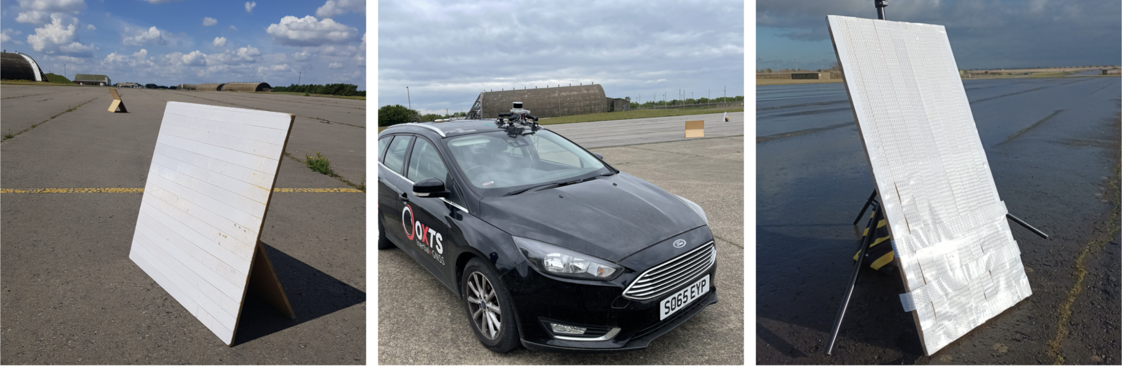
Data-Driven Boresight Calibration
One of the most challenging parts of the lidar survey set-up process is aligning the coordinate frames of the lidar and INS devices. Failure to align these with sufficient accuracy can lead to blurring and double-vision in point clouds.
Many surveyors try to do this by eye, or by developing expensive CAD models, however there is a simpler, quicker and more cost-effective way – using data.
Built into OxTS’ lidar georeferencing software OxTS Georeferencer, there is an optional boresight calibration tool. It requires the surveyor to survey two static “targets” (see the images below) from multiple distances and angles. The data is then calibrated, and the angle displacement calculated to a tenth of a degree.
OxTS Georeferencer includes an optional boresight calibration tool. (Photos: OxTS)
Once the initial boresight calibration has taken place, if the setup is not altered in any way, the coordinate frame alignment will be valid for any future survey.
The Future
In the coming weeks and months, the development of new hardware and software features will further streamline the survey process.
Hexagon | NovAtel’s CPT7 integrates a GNSS receiver and an INS to deliver up to centimeter-level accuracy. (Photo: Hexagon | NovAtel)
We discussed mobile mapping with Bryan Leedham, product manager of enclosures and post-processing software, NovAtel, Autonomy & Positioning division, Hexagon.
How do you define mobile mapping?
It is getting broader in scope, as more folks find reasons to map the world. The key goal is to capture reality from mobile platforms to build a digital representation of reality for some large area, such as a city, a road or a factory. Most of the time, that means from a ground vehicle on public roads.
It’s also safer and faster than traditional surveying because you don’t have to stop traffic or dodge it.
Right! In an ideal world, rather than spending days setting up traditional survey equipment, you could strap some sensors on a mobile platform and gather accurate map data in minutes.
What are the key remaining technical challenges?
Picture one of Google’s or Waymo’s mapping vehicles. The first sensors that come to mind are GNSS, inertial, lidar and radar. Each of those has its own unique strengths and weaknesses. The first technical challenge that remains is to mature each of those technologies for a lower enough cost that it’s affordable.
Right now, mobile-mapping vehicles are quite expensive, especially in areas where some of these sensors will struggle more than others. To map very dense urban spaces — with underground areas, overpasses and tall buildings where GPS is challenged — you need a very strong localization system that can survive those conditions for however long it takes to drive through them. If I’m building a car to map rural Alberta, I could choose much cheaper sensors than if I were trying to map downtown Chicago every week.
On the flip side, you must deal with the massive amounts of data collected.
Yes, that is a very large challenge. Lidar data, in particular, is guilty of generating very large point clouds. It’s a balancing act. More accurate and higher resolution maps require lidar sensors with even denser point clouds. So, you need data management and sufficient processing power to get accurate results quickly.
What are the key technical challenges in sensor fusion?
Sensor fusion is how we approach the goal of mapping as accurately as possible in increasingly difficult environments. On their own, GNSS receivers struggle in obstructed areas but, when you pair them with other sensors, they become very complementary.
Lidar and cameras, for example, are quite good at measuring the distance to nearby objects and at classifying them, but they have no idea where they are relative to one another. Likewise, if you let an IMU [inertial measurement unit] sit in your car, it will no longer know its location. However, once you give it a position update, it is very good at maintaining a trajectory over a short period of time. When you combine absolute and relative localization, all the sensors play to their own strengths.
What is NovAtel’s SPAN software?
It stands for synchronous position, attitude and navigation. It is the sensor-fusion software that combines the GNSS, inertial and whatever other sensors. It is based on core NovAtel GNSS receiver software. We can use NovAtel receivers in combination with IMUs from a wide range of manufacturers and, in the future, hopefully, other sensors from a variety of manufacturers as well.
SPAN started with blending just GNSS and inertial but we’re now researching how to bring in such things as lidar and cameras. Autonomous Stuff, another Hexagon company, works on the greater sensor fusion using SPAN as well.
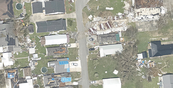
High-resolution imagery geolocated by the sixth-generation Digital Sensor System (DSS) after Hurricane Ida. (Photo: NOAA)
Applanix, a division of Trimble, has been working with the National Oceanographic and Atmospheric Administration (NOAA) since the early 2000s to develop their response for emergency and coastal mapping activities. We discussed this collaboration with Joe Hutton, the company’s director of inertial technology, land and airborne products.
How has Applanix collaborated with NOAA regarding emergency response and coastal mapping?
Early on, we worked with them to develop a solution that allowed them to get out in the field and produce high accuracy map products with minimal touching of the data. In mid-2021, we delivered the next generation of this solution, or the DSS version six, which represents the culmination of everything learned over the years about how to produce imagery for emergency response, in terms of the types of collection, the types of imagery, and how to get it into first responders’ hands as quickly as possible.
At the heart of the system is our direct georeferencing technology. It’s a solution that allows us to assign the geographic location of every pixel of the digital imagery collected in the air. As soon as you land, you have the coordinates of every pixel, which means that you have a map that NOAA then pushes to the cloud for first responders to use in their emergency response efforts.
The collaboration consisted of Applanix working with Lead’Air to manufacture the next generation system that meets NOAA’s latest requirements. That’s what we delivered in 2021. Weeks after delivery, NOAA was called to respond to the hurricanes. They flew the new system with great success and were able to use it for their response.
What is your perspective on ground control points (GCPs) vs. direct georeferencing?
It is impossible to place GCPs in an emergency response when you cannot get on the ground. People who say they need GCPs do not really understand direct georeferencing. We’re having this debate even after 20 years of proving this technology. The NOAA system does not use GCPs and the map products are at centimeter level accuracy.
We use Trimble’s RTX technology, which enables centimeter-level GNSS positioning without base stations, which is important when the CORS or local RTN is unreliable due to a disaster. We have high accuracy inertial systems that get us the high accuracy orientation, so that we can go directly to ortho photos and ortho mosaics without running any triangulation or using GCPs in that process. That is a standard process these days. GCPs are only there for quality control if you want to deliver a final map product.
Did NOAA fly the mission with its own aircraft?
Yes, these are NOAA’s King Air or Twin Otter aircraft. The King Air aircraft is specifically outfitted for these types of emergency response and coastal mapping activities. The DSS system gets installed into the airplane and gets calibrated in terms of checking the system out for accuracy. Then it’s ready to fly the response. In the air, they collect the imagery over a flight path of interest to them. Then, it’s developed from raw imagery into JPEGs in the aircraft, and all the georeferencing data is logged with that imagery so that as soon as they land they can push a button and start to reference the JPEG imagery and push it to the cloud.
What are the components of your system?
What makes this system so unique is that it encompasses all the lessons learned over the years in terms of what NOAA needs to optimize for both their coastal mapping and their emergency response. It incorporates two pairs of color and near-infrared Phase One cameras that are configured in an oblique format with some overlap, forming a bowtie footprint on the ground.
You have 100% overlap of the color with the near-infrared and it’s on a high-performance stabilized mount that keeps everything perfectly level. The mount also has a special feature that enables the operators to rotate the cameras to go into nadir mode, mostly for traditional coastal mapping that requires stereo imagery. We were able to incorporate into a single system the requirements for both emergency response—where you want large coverage and obliqueness to look for damage—and nadir for coastal mapping.
Lead’Air built the sensor for you, on your specs, correct?
Yes, that’s correct. We’ve worked with Lead’Air for probably 20 years on flight management system (FMS) technology. They also have an amazing capability to build stabilized mounts and hardware systems. So, we decided to work together. We contracted them to implement some of their innovative hardware in this new design for us to deliver to NOAA. We contracted them to do all the manufacturing of the design and delivery to NOAA.
One of the quite innovative things that they did was to develop a new flight management capability that allows NOAA to fly ad hoc along highways or rivers, looking for damage. Traditionally, for aerial imagery you have to pre-flight plan trajectories. They designed an FMS that enables a pilot to fly a road or a river looking for damage without worrying about traditional block collections as with a more traditional FMS. So that feature further increases productivity. If you look at the most recent imagery at www.storms.ngs.noaa.gov you will see that it looks like spaghetti, not like blocks. That’s because they are following the roads and the rivers looking for specific damage.
Does the post-processing use your software?
Yes, it uses the POSPac MMS post processing software with POSPac Trimble Post-processed CenterPoint RTX correction service, allowing us to get that centimeter-level position accuracy, anywhere in the world with just an internet connection. You don’t have to worry about having a local base station—which, of course, if you’re in an emergency response situation, might not be there anyway. So, this is a very powerful way of getting global centimeter-level accuracy in real time, without having to worry about the ground-based GNSS infrastructure, that is, the local real-time network, that’s on the ground.
If you don’t have internet access, you can ship that data to the nearest place that does, right?
You could, however NOAA simply flies to wherever there is access. What takes the longest is to develop the imagery from the raw format to the JPEG format, because these are such large images. Doing that in the air saves an enormous amount of time. You have these JPEG-ready images that are compressed and can go right into the georeferencing process and make it really, really fast.
That’s a matter of computing power and smart software. What else did Lead’Air contribute?
This very efficient, fast image development process in the aircraft.
It sounds like it was a very integrated process between Applanix and Lead’Air. So, NOAA had the instrument mounted on their aircraft, their pilots did the flying, and then you processed the data?
No, NOAA’s team processes all the data. We just deliver the hardware and the software. They created the workflow software to push the data to their cloud environment.
NOAA uses this data to produce maps of the damage and highlight different situations and hazards?
Yeah. When these hurricanes go through, the first questions people have are “Where’s the damage? Are these roads passable? Did my house survive?” If you are doing response, you need to get teams in there. First, however, you need to know whether the roads are passable, so that you will not waste time going down a road that is not. So, the first thing they do is go up in the air and survey the main roads to push the imagery back, so that people can assess whether the roads are passable. Then they start to look for specific areas of damaged infrastructure, to triage where to put their resources. Then they ask “How do we manage disaster recovery?”
What lessons did you learn?
We are still learning about the power of the system, because these are Phase One 150 megapixel color cameras. It is such a powerful combination of sensors that they’re starting to look at different information they can get out of these things. They’re still learning new lessons in terms of what information can be useful for both the emergency response and the coastal mapping.
Ultimately, we’ll go to full ortho maps in the aircraft. That’s just going to be a matter of computational power. The holy grail would be to produce an orthophoto in the aircraft and radio it down to the ground in real time. Nothing prevents you from doing that now other than computational power and bandwidth. It’s not practical yet, but it will probably get there.
Do you have collaborations like the one with NOAA with any other major U.S. agencies?
We’ve worked extensively with NASA over the years. For example, we have worked with them on the ice bridge project. That is where they survey ice at both poles to measure its thickness and how global warming is affecting it. They use our system on that to do the georeferencing. We also work extensively with other branches of NOAA for their shoreline mapping from their ships. We have worked with them over the years to provide the georeferencing solution for the multibeam echo sounders to produce their nautical charts.