The April column also highlighted one of NGS’ four use cases – “Use Case 1: Flood Mapping.” The case study discusses the Elevation Certificate (CE) Example, Flood Insurance Rate Map (FIRM) and Flood Insurance Study (FIS).
The column highlighted the potential effects of subsidence on published heights in the Houston region, which implied that most of the published heights that are based on older surveys in the region are not current or accurate.
This column will provide more details of the suppression of heights in the Southeast Texas region, and potential effects of crustal movement on published heights in other regions of the United States.
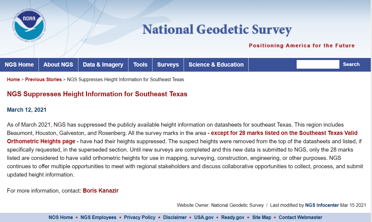
NGS announcement that it suppressed height information for Southeast Texas. (Image: NGS)
According to NGS’ announcement, only 28 marks will have publicly available orthometric heights on NGS datasheets in Southeast Texas.
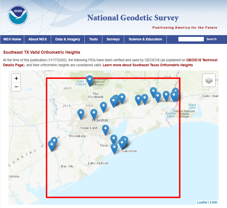
The “Link to Map: SE TX Valid Ortho. Heights” button provides the benchmarks available to users (see the box titled “Link to Map SE TX Valid Ortho Heights”). The website provides links to the published stations.
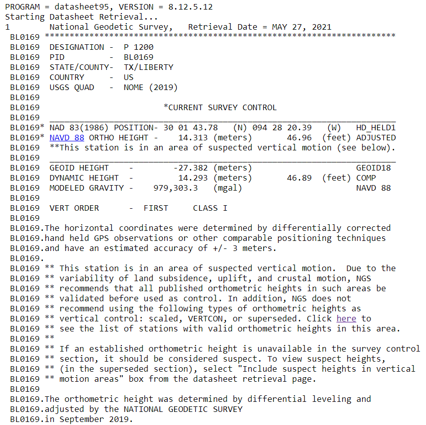
Clicking on an icon provides the PID and name of the station with a link to a datasheet. Click “Get Datasheet” for a datasheet of the station. Below is an excerpt from the datasheet of Station P 1200.
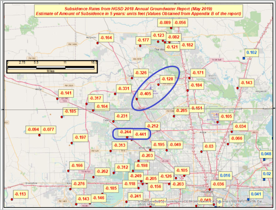
Let’s address why NGS is suppressing the stations in Southeast Texas. My last column provided plots depicting the amount of movement in the Harris-Galveston, Texas, region. See the box titled “Estimate of Amount of Subsidence in 5 Years in Harris-Galveston, Texas, Region – Units Feet.”
As indicated in the plot, some of the marks are estimated to have moved almost ½ foot (approximately 0.15 meters) in 5 years. In addition, some of the relative height differences approach 1/3 of a foot (approximately 0.1 meter) between neighboring stations. See the highlighted stations in the box titled “Estimate of Amount of Subsidence in 5 Years in Harris-Galveston, Texas, Region – Units Feet.”
The last major releveling incorporated into NGS’ Database in the Harris-Galveston, Texas, region was performed more than 30 years ago in the 1986/1987 timeframe. Therefore, some of the published stations in the region could have subsided more than three feet (or about a meter).
As stated in NGS’ Blueprint 3, “Most leveling data in NGS archives comes from the mid-20th century, in support of the NAVD 88 project.” Of course, most regions of the United States are not subsiding at the same rates as in the Houston-Galveston, Texas, region.
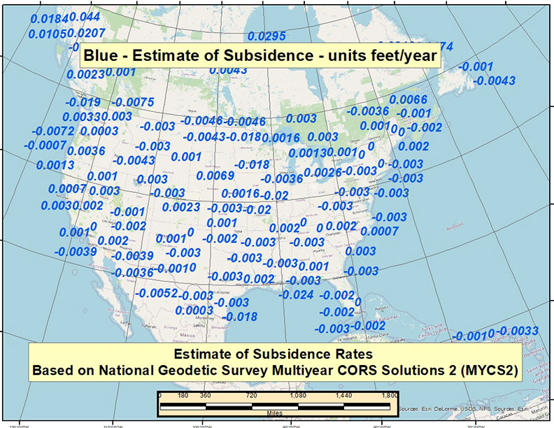
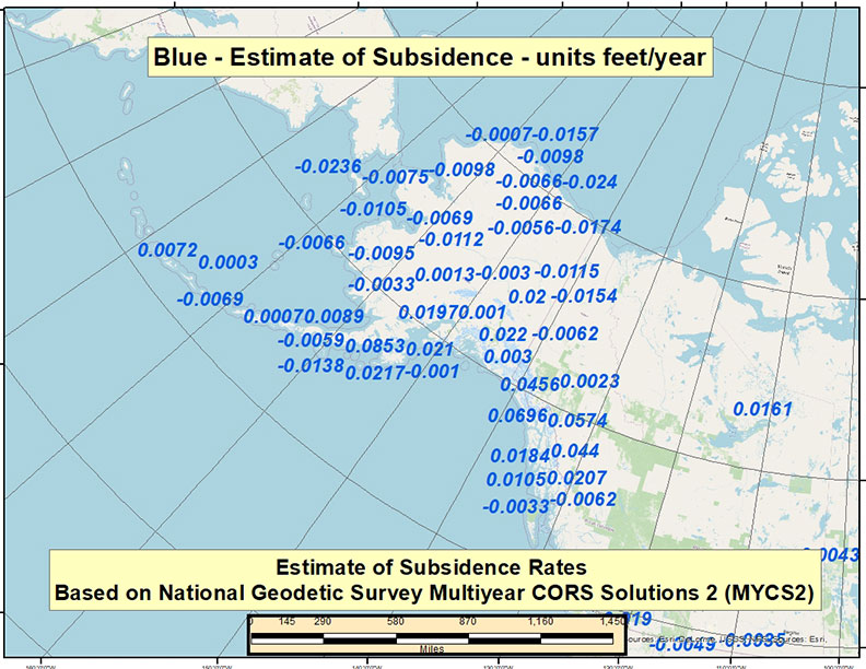
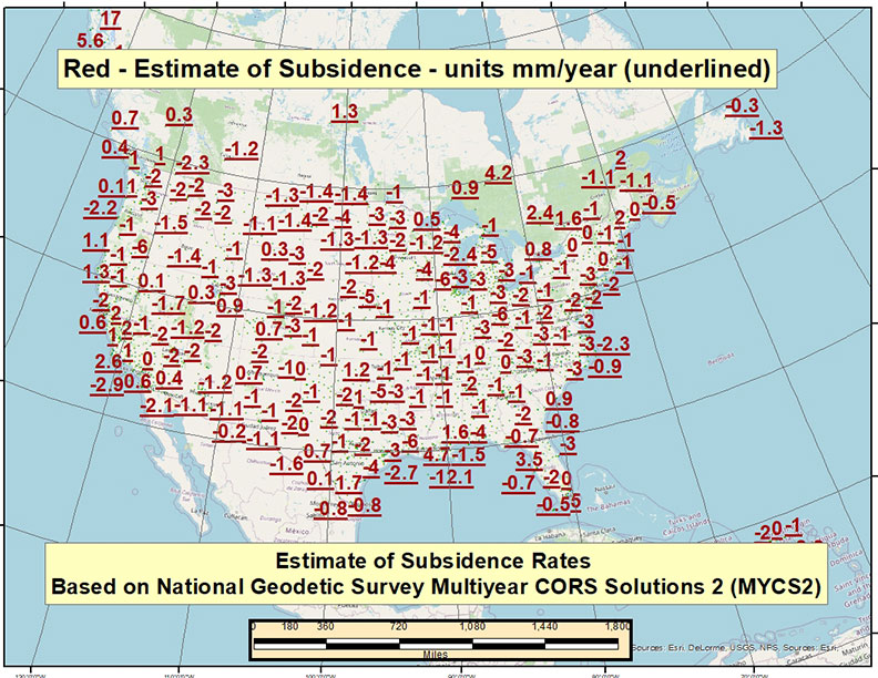
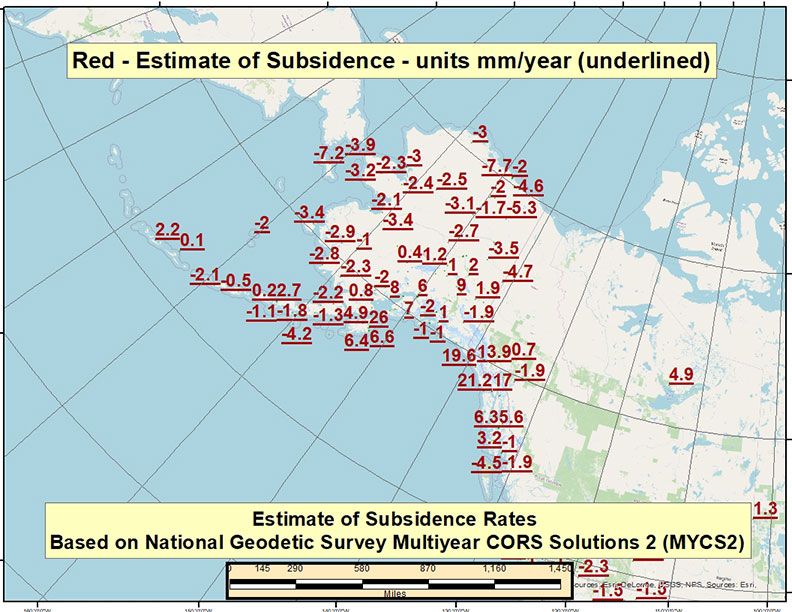
In a previous newsletter, I discussed NGS’ second Multi-Year CORS Solution of the National CORS (MYCS2). I downloaded the coordinates and velocities from NGS’ website and created a plot of the vertical velocities. For those who prefer to use feet as opposed to meters, I provided velocities with units in feet/year and mm/year.
See the boxes titled “Estimate of Velocity Rates Based on MYCS2 – CONUS (feet/year),” “Estimate of Velocity Rates Based on MYCS2 – Alaska (feet/year),” “Estimate of Velocity Rates Based on MYCS2 – CONUS (mm/year)” and “Estimate of Velocity Rates Based on MYCS2 – Alaska (mm/year).”
It should be noted that the intent of these four plots is to provide a wide-ranging view of the values and some of the variation in rates across the United States.
Estimate of Velocity Rates Based on MYCS2 – CONUS (feet/year). (Image: David Zilkoski)Estimate of Velocity Rates Based on MYCS2 – CONUS (feet/year). (Image: David Zilkoski)Estimate of Velocity Rates Based on MYCS2 – CONUS (mm/year). (Image: David Zilkoski)Estimate of Velocity Rates Based on MYCS2 – Alaska (mm/year). (Image: David Zilkoski)
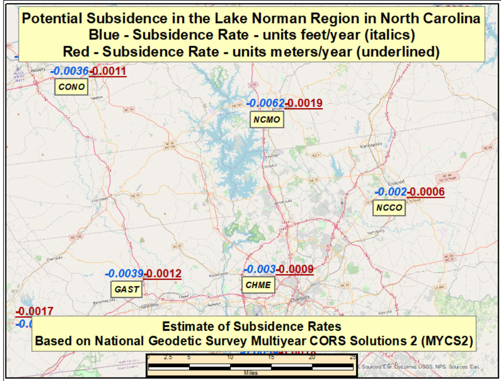
The rates appear to be small in most regions of the United States. As an example, the rates are all less than -0.0062 feet/year (-0.0019 meters/year) in the Lake Norman region in North Carolina (see the box titled “Potential Subsidence Rates in the Lake Norman Region in North Carolina). It would take many years for the crustal movement to make a difference to some projects in this region.
Potential Subsidence Rates in the Lake Norman Region in North Carolina. (Image: David Zilkoski)
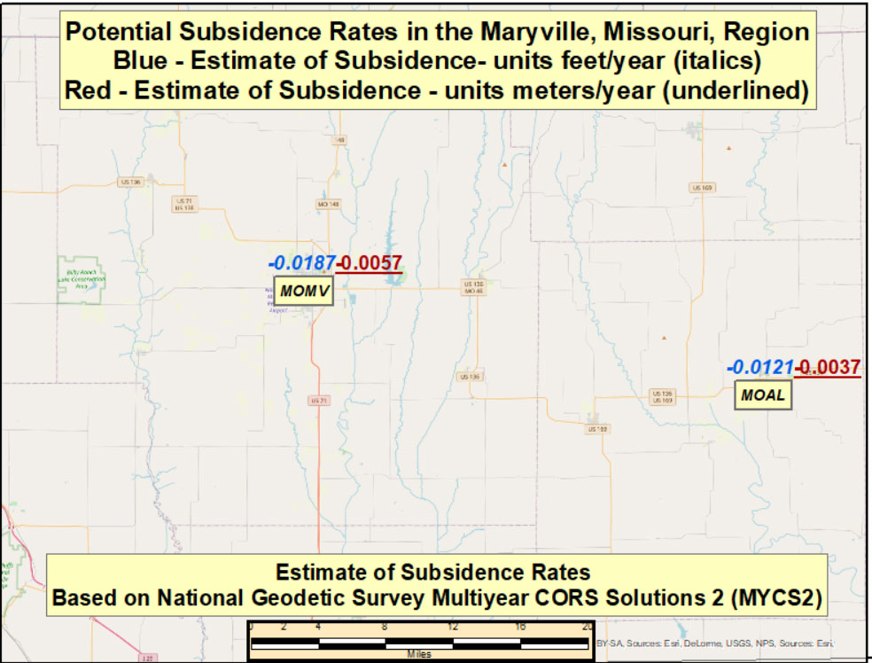
That said, let’s look at another region of the country. For example, in the vicinity of Maryville, Missouri, the rate of subsidence is around -0.0187 feet/year (-0.0057 meters/year). See the box titled “Potential Subsidence Rates in the Maryville, Missouri, Region.” These subsidence rates don’t appear to be large values but if you take into account the last time the height of a mark was established by leveling data it could result in a large difference from the true orthometric height.
Potential Subsidence Rates in the Maryville, Missouri, Region. (Image: David Zilkoski)
According to NGS’ database, it appears that many of the marks in the Maryville, Missouri, region were last leveled in 1935. I used NGS’ Passive Mark Lookup tool and Leveling Project Page tool to identify the marks and associated leveling lines in the area of the CORS stations in the Maryville, Missouri, region.
I described the Passive Mark Lookup webtool in a previous column. As previously mentioned, these subsidence rates all seem very small, but if you take into account the last time the height of mark was established by leveling data, the subsidence value can be very large.
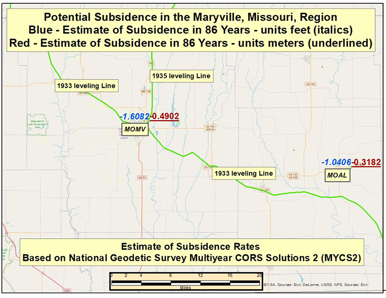
See the box titled “Potential Subsidence in 86 Years in the Maryville, Missouri, Region.” The box indicates that, if you account for the last 86 years (2021 – 1935), the potential subsidence exceeds 1½ feet (-1.6082 feet, -0.4902 meters).
Potential Subsidence in 86 Years in the Maryville, Missouri, Region. (Image: David Zilkoski)
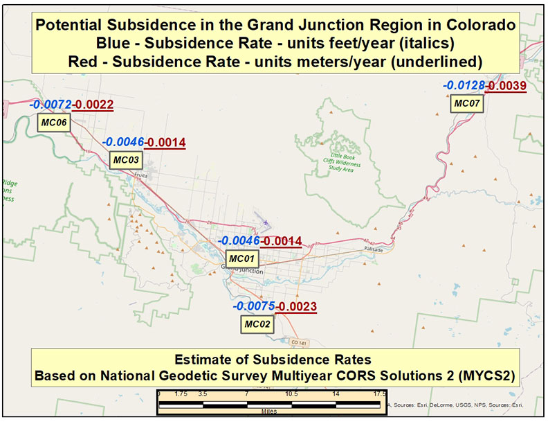
Continuing across the country to Colorado, the box titled “Potential Subsidence Rates in the Grand Junction Region, Colorado,” provides the estimate of subsidence rates in Mesa County, Colorado. As the plot indicates, the rates vary between -0.0046 feet/year (-1.4 mm/year) and -0.0128 feet/year (-3.9 mm/year). Once again, these rates all seem relatively small but many of the marks near CORS MC06 were last leveled in 1985. This means the potential change in height could be as large as 0.2592 feet (0.0792 meters).
Potential Subsidence Rates in the Grand Junction Region, Colorado. (Image: David Zilkoski)
Obviously, this is only an estimate of the subsidence in the region and the actual amount of subsidence is unknown since the last time the mark was leveled. These estimates are based on the MYCS2, which uses current data to estimate the velocity. The processing included data spanning 1996 to 2016 (week 0834 to 1933), 1099 weeks or about 21 years in total.
The point of this column is not to provide the exact change in height of a mark, but to highlight that the publicly available orthometric height on a NGS datasheet may not be up to date based on crustal movement. The new modernized National Spatial Reference System will enable users to determine an accurate, current height on a mark and be able to efficiently and effectively monitor changes in a mark’s height.
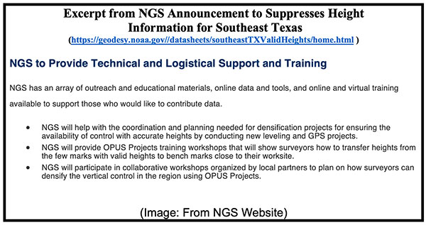
As stated in NGS’ announcement to suppress the heights in Southeast Texas, the agency has developed tools to assist users in submitted data to NGS. See the box titled “Excerpt from NGS Announcement to Suppresses Height Information for Southeast Texas.”
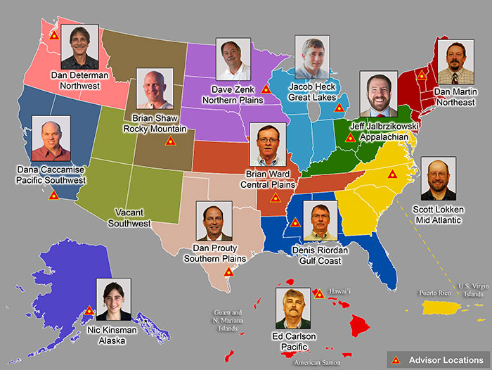
This assistance is for every user, not just for individuals performing surveys in Southeast Texas. NGS has Regional Geodetic Advisors throughout the United States.
The Regional Geodetic Advisors provide guidance and assistance to constituents within their region. They are subject-matter experts in geodesy and regional geodetic issues. These individuals can assist users that are planning GNSS campaigns to re-densify the network.
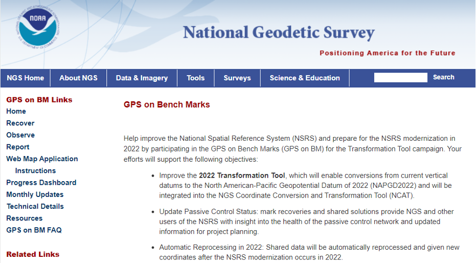
As mentioned in previous newsletters, a benefit of the new modernized National Spatial Reference System (NSRS) will facilitate the establishment of consistent, accurate NAPGD2022 GNSS-derived orthometric heights.
This column provided details on the suppression of heights in the Southeast Texas region, and potential effects of crustal movement on published heights in other regions of the United States. NGS suppressed the heights in the Southeast Texas region because of the large amount of crustal movement since the last time the heights of the marks were established.
As indicated by NGS’ MYCS2 velocities, every mark could be affected by crustal movement. In my opinion, the question a user should be asking is “How much has the height of the mark changed since it was last determined? Not, “Has the height of the mark changed?”
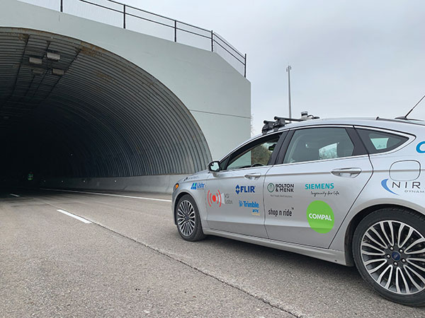
Autonomous vehicles are being tested both on open roads and in controlled environments. (Photo: Trimble)
The advent of autonomous vehicles (AVs) is one of three revolutions in the automotive industry that will likely change this country as much as cars did over the last century. The other two are the conversion from internal combustion engines to electric ones and the integration of cars into digital traffic networks.
Once mass deployed, AVs promise to dramatically reduce the number of traffic fatalities (42,000 in the United States in 2020, a National Safety Council report shows). They will never be sleepy, distracted, aggressive or drunk — nor will they engage in such inane human driving behaviors as texting while driving, playing chicken with bicyclists, or running red lights. They also promise to reduce fuel consumption, harmful emissions and traffic congestion by optimizing routes and increasing the number of people using car services instead of owning their own car.
To realize this vision, however, cars will have to do a lot more than just find their way on their own. They will have to perform flawlessly in an unpredictable world that includes toddlers, reckless drivers, fallen trees, sinkholes, construction and accidents.
Among the many sensors aboard an AV, the GNSS receiver has a unique role. It is the only one that can provide absolute positioning, in the form of latitude and longitude coordinates, to within a couple of decimeters anywhere on Earth. As such, it is “a key enabler to a lot of the vehicles to know precisely where they are and whether it is safe to activate autonomous systems,” says Gordon Heidinger, automotive segment manager, Autonomy and Positioning division at Hexagon.
A GNSS receiver cannot achieve the level of accuracy required for autonomous driving without robust corrections. Fifteen years ago, the state of the art was real-time kinematic (RTK) corrections. However, “the cost of that equipment exceeded the cost of a small car at that time,” recalled Steve Ruff, general manager, On-Road Autonomy Division at Trimble. “They were targeting a system cost of about $200. Today, that number is below $50, including the antenna, the GNSS positioning engine, and the software that runs on it.”
Today, all automotive manufacturers are using a form of precise point positioning (PPP) corrections, which is a one-way broadcast, as opposed to the two-way communication between a base station and a rover required for RTK. This means that a single correction stream can serve an entire continent, Ruff pointed out. “Once a vehicle is manufactured, we will support it with our PPP corrections stream for at least 10 years, which is the typical service life of a vehicle.”
Obstacles to Adoption
To achieve mass-market adoption, AVs will have to overcome numerous and complex obstacles:
The technical difficulty of dealing with a limitless number of unanticipated challenges, such as poor visibility because of weather conditions, unpredictable human behaviors, complicated obstructions, detours and potholes
The need to map millions of miles of roads, develop vehicle-to-vehicle (V2V) and vehicle-to-infrastructure (V2I) communications, and protect vehicle software from hackers
The difficulty, if not the impossibility, of handing off control to a human quickly enough to be safe when the system is unable to deal with a complex situation
Questions about legal responsibility and insurance liability
Ethical dilemmas about how to program the system to respond in emergencies
The development of appropriate federal and state regulations
Resistance from paid drivers who fear losing their jobs, including 3 million U.S. truckers, and from many other drivers, who fear losing control over their safety.
Trimble has approached all the major car manufacturers, has several programs in development, and has received multiple positioning requests for information (RFIs), Ruff said. “In 2018, Trimble’s RTX corrections service was the first solution adopted for production use in passenger vehicles, providing absolute precise positioning for General Motors’ Super Cruise system.”
Additionally, Trimble is working with Qualcomm and with SiriusXM, which will deliver Trimble’s RTX corrections over its satellite network, just like it does with music. “It is a good partnership because about 80% of the vehicles in North America are coming equipped with SiriusXM radio technology,” Ruff said. “The OEMs do not have to buy any additional hardware.” RTX corrections can also enter a vehicle via cellular IP, L-band satellite broadcasts and, potentially, over a V2I link.
Hexagon has proposed a PPP solution for automotive, “mainly because we essentially have the world covered with base stations, and that is a hard thing to do,” Heidinger said. “We have been running a corrections network for a very long time.” PPP’s one-way broadcast offers better cybersecurity because the GNSS receiver does not have to disclose its position, he added.
Swift Navigation is building a global corrections network. To make it suitable for the automotive market, the company is aiming to make its corrections service affordable and scalable. “We realized quickly that neither of the traditional RTK and PPP approaches were going to meet those requirements,” said Fergus Noble, company co-founder and CTO, “so we invested in developing a corrections service pretty much from the ground up.”
RTK provides high accuracy and short convergence times but is typically costly to deploy because it requires a very high density of stations, Fergus explained. As a consequence, most providers do not have continuous coverage over a wide area. Conversely, while PPP is a true global solution, it is less accurate and takes a long time to converge. “That may be fine in a marine or land-surveying application, but not if you are driving through city tunnels and bridges and need it to be able to reacquire a high-accuracy position within a matter of seconds. Therefore, we took a hybrid approach, together with a lot of new IP that we developed.” The service provides coverage in all the United States and most of Europe, and is being tested in Japan, South Korea and Australia.
Accuracy and Integrity
A common target accuracy for lane-level positioning is 20 cm 95% of the time. That means that AVs need to know when their positioning accuracy falls beneath that threshold. “We are building into our positioning solutions an accuracy metric that is output along with the position information we are providing,” Ruff said. “[The metric] can be used by the intelligence in the system to decide whether it can rely on the GNSS solution or needs to switch to one of the other complementary technologies because GNSS accuracy is not fulfilling its lane discipline.”
Heidinger noted the importance of economies of scale when mass-producing vehicles, where cost and ease of manufacturing become factors. “We can take some of our high-end equipment and get you 2 cm of accuracy with this technology, but the price point and the feasibility of this going into mass production for automotive is not favorable,” he said. “So, we’ve taken the approach of providing a software positioning engine that can be fit onto any hardware.”
Hexagon is developing products in partnership with STMicroelectronics, using the company’s Teseo V family of measurement engines. “ST is one of the established leaders of automotive GNSS solutions,” Heidinger said. “We take their measurements and put our positioning and corrections solution behind that to give positioning with lane-level accuracy.”
Noble agrees on the importance of knowing the reliability of a vehicle’s GNSS-based lane accuracy. The prevailing approach, which fuses data from GNSS and other sensors, makes it acceptable for one data source to be temporarily unavailable if the system is aware of that outage, he said. “That is where you start to see Swift, and others as well, focusing on the notion of integrity.”
An AV’s level of autonomy determines its behavior during GNSS outages. For systems with Level 2 autonomy and below, the driver must remain engaged, while Level 2+ and Level 3 systems will alert the driver to retake control when needed. If a driver of a Level 2+ or higher system fails to reengage, the AV’s reaction depends on the system and manufacturer.
“When we start to see Level 3 or above self-driving systems come onto the market, they will require that the GNSS component has an ISO 26262 safety certification,” Ruff said. “Many companies, including Trimble, are going through, or have gone through, the process of safety-certifying their offerings. As part of the AV system’s safety architecture, they will build in the capability to safely curb the vehicle if the system detects a malfunction or a spoof or some other type of problem.”
Automation Levels
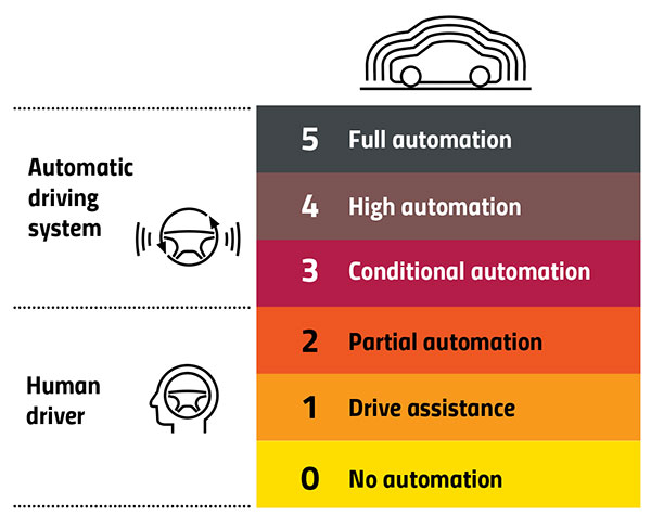
In 2014, the international Society of Automotive Engineers released a standard, adopted in 2016 by the U.S. National Highway Traffic Safety Administration, that classifies cars in six levels, ranging from Level 0 (no automation) to Level 5 (full automation, meaning vehicles that can handle the full spectrum of road and traffic scenarios without any assistance from the driver). While many production models already incorporate various forms of Level 1 driver assistance, no current production car exceeds Level 2, or partial automation, which requires the driver to monitor the vehicle’s surroundings and take over as necessary. No test vehicle has yet achieved Level 5.
Image: GPS World
Other Sensors
Beyond lane-level positional accuracy, safe driving also requires avoiding collisions with other vehicles in the same lane or straying into it. Cameras, lidar and radar will detect other vehicles as well as fixed infrastructure and random obstacles, measure their distance, and monitor their movement.
While lidar scanners are better than cameras as detecting sharp-edged features, such as curbs, cameras are better at detecting and interpreting visual cues, such as road signs and the location and curvature of lane markers. In bad weather, radar is essential, because radio waves, unlike light waves, can penetrate rain, snow, fog and even dust, enabling radar to “see” where cameras and lidar cannot. However, radar sensors cannot see much detail, and cameras do not perform well in conditions with low light or glare.
Besides providing data about a vehicle’s trajectory, inertial navigation systems (INS) also measure its attitude (roll, pitch and yaw), enabling the software to better correlate and interpret data from the other sensors.
For example, when a car brakes sharply, its front end goes down; any forward-facing sensors measure distances to points closer to the car than they did a moment earlier, when its chassis was parallel to the street surface.
INS can also detect unsafe conditions, such as excessive slip angle, which is the angle between the direction of the rolling wheels and the vehicle’s true heading. A slip angle as small as 0.5 degrees can trigger skidding, spins or rollover, especially in the case of SUVs and tall trucks. Wheel-speed sensors also help verify the vehicle’s movement.
“All these technologies have their limitations,” Ruff said. “However, if you design the system, including all these technologies, then you can come up with a robust, safe combination that will enable autonomous driving.”
In addition to helping to avoid collisions, these other sensors provide relative positioning by comparing the images they acquire with highly precise maps to help locate the vehicle, especially in urban environments, which are well mapped and rich in recognizable landmarks.
Imagine an AV moving through different environments. It might travel from a city with urban canyons that degrade GNSS navigation, yet with landmarks that help relative positioning, to a rural environment devoid of both. The AVs’ algorithms must constantly weigh how much to rely on the different sensors. “Many of the OEMs and car companies are seeing that even rain mist on a highway is very bad for lidar and cameras, because it creates a big blur, but that is where GNSS will perform really well because it is open sky,” Heidinger said. “So, the two types of sensor systems complement each other very well.”
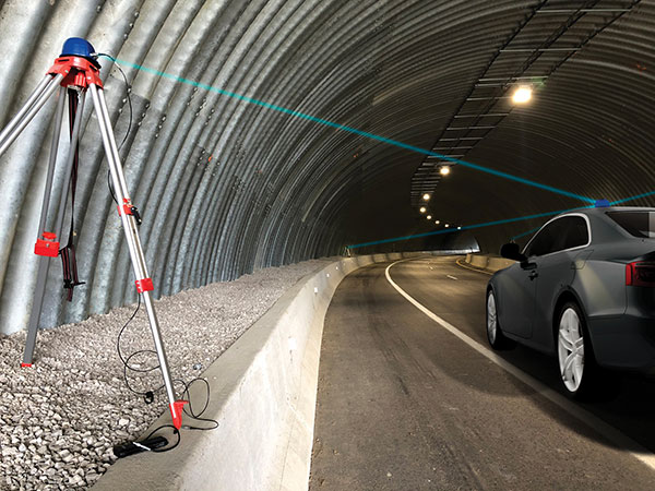
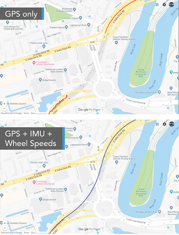
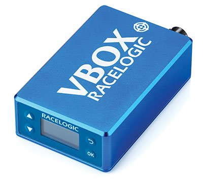
“Odometry sensors, such as a wheel-speed sensors, minimize any potential drift and add robustness to data that may have a GNSS outage of greater than 5 seconds, such as longer tunnels,” said Wesley Hulshof, principal engineer – ADAS Testing at Racelogic.
Photo: Racelogic
Noble sees a split in the industry. Companies such as Waymo and Cruise are pursuing Level 5 autonomy and are “heavy users of lidar” as well as other sensors. Companies such as Swift are focusing on Level 2 and Level 3 series production vehicles. “If you are making a mass manufactured vehicle for the production market, it rules out using a lidar sensor,” Noble said. “It is just too costly and complex right now to use. So, typically, if you look at the systems that are out on the market today, such as a Tesla Autopilot or a GM Super Cruise, they are very reliant on the camera as the primary sensor. Obviously, also inertial and some use of radar.”
Maps and Communications
While accurate and up-to-date maps have an important role to play in making autonomous driving possible, the more detailed maps are, the more the world they describe is constantly changing.
Meanwhile, the sensors keep improving and dropping in price, making maps less important. In the end, AVs — like human drivers — will probably rely much more on their ability to “see” and analyze their environment moment-to-moment.
Also like their human counterparts, they will gain experience. Unlike human drivers, however, AVs will be able to instantly share their experience with every other vehicle in their area via vehicle-to-vehicle (V2V) and vehicle-to-infrastructure (V2I) communications.
V2V communications will enhance safety by informing AVs of the trajectories of nearby vehicles. If a vehicle is speeding toward an intersection and not slowing for a red light, it will be communicating its position and trajectory to other cars over a V2V link, Ruff explained.
“Then your car can make the intelligent decision to pump the brakes and avoid that collision. The same positioning stack that operates as part of the AV stack can also be used to support V2V-type applications, and the position of the vehicle will be much better than what the current V2V spec states.”
Different Approaches
Each GNSS manufacturer is taking a different approach to AV positioning.
The worlds of traditional automotive positioning and the products on which NovAtel has historically focused are coming together, Heidinger said. “The autonomous technology is demanding it and pushing for higher performance and safety-of-life functionality. Hexagon is bringing high-performance positioning solutions to the automotive industry in a manner that accepts automotive manufacturability, quality and efficiency.”
The company has also joined the 5G Automotive Association (5GAA), a large consortium developing AV solutions. “There are probably 100 companies in the industry coming together and helping to develop that vehicle-to-network communications solution, including telecom partners and automotive partners, and we are providing the GNSS expertise,” Heidinger said. “To meet the high-volume production-intent applications, including automotive quality, we recently developed a receiver based off the ST Teseo V family of measurement engines. We have an ST Teseo V set of chips on the PIM 222A product that launched in May geared exactly toward the automotive market.”
By contrast, Trimble is not focused on providing GNSS receivers or other hardware. “We allow the Tier 1 automotive manufacturers to architect the system using the components that they have selected from their preferred suppliers,” Ruff said. “We tailor our positioning solution to work with their architecture. So, we are agnostic as to the selection of the GNSS receiver, the IMU, the operating system running on the host system, and the host processor that runs the software. We can adapt our stack to run on virtually any system, using measurements from any GNSS source that meets our API requirements.”
For Swift, its “vision from day one has been to bring this type of precise positioning technology to mass market applications, such as automotive, which is a big focus for us,” Noble said. “That includes autonomy, but also ADAS, HD navigation and V2X. We do not want to be a hardware supplier in the automotive supply chain. Our boards are focused on professional and industrial markets.”
Swift’s automotive software, called Starling, runs on the vehicle’s computer. To generate a precise position, it ingests raw sensor data, as well as corrections data from the company’s Skylark network. “We focus on providing a precise-positioning stack that layers on top of any of this current generation of low-cost, automotive-grade receiver hardware from companies like STMicroelectronics.”
This test in London shows the value of inertial and wheel speed sensors. (Image: Racelogic)
The Future
Speculation abounds as to when AVs will enter mass production and how the transition from human to robotic drivers will take place. “There might be a ‘classics only’ lane in the future,” Heidinger said “that will be the only place where cars are allowed to be driven manually.”
Safety-enhancing automotive devices typically start out as optional extras, then get incorporated into best-practice standards promoted by independent bodies. Eventually, they become compulsory.
Some automakers have committed to creating their own AVs, while others are intent on creating a turnkey solution to transform conventional cars into driverless models. However, the initial market for AVs likely will be commercial fleets rather than individual consumers.
“It will still take quite a few years before we see cars take over and drive themselves, because legislation, insurance and these sorts of things will have to happen along with the technological advances,” Heidinger said. “But the positioning side is becoming more defined. We are seeing things like L5, the Galileo constellation, coming in and becoming more available. There are more constellations providing more data for use in our solutions, so that is promising.”
Swift’s Noble said, “Most of the major manufacturers working on Level 2+ and Level 3 systems are realizing that precision GNSS will be a key component of their architecture. Most of the major OEMs have signaled some level of intent to integrate this technology. Most are tracking to start the program next year,” he added.
“We envision that in five or six years every vehicle will have a single positioning utility on board that will serve all the location-aware applications on the car — whether it is an autonomous vehicle, V2V or V2I,” Ruff said. “It will meet the most stringent accuracy requirements from all the applications and serve navigation, telematics, security, V2X and AV/ADAS applications.”
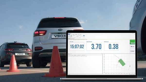
A test of Racelogic’s parking assistance system. (Photo: Racelogic)
Racelogic helps vehicle manufacturers develop autonomous vehicle technology and test them on indoor test tracks and the open road.
Racelogic helps vehicle manufacturers develop autonomous vehicle (AV) technology and testing houses test them. Over time, regulatory and consumer testing has evolved from indoor test tracks to outdoor open-road tests, and then to indoor controlled test environments.
“Due to their application, advanced driver-assistance systems (ADAS) originated and are still mainly developed and assessed on open-sky, controlled test tracks, tackling the most common killed and seriously injured (KSI) accident types,” said Wesley Hulshof, principal engineer – ADAS Testing at Racelogic. “These assessments usually make use of sophisticated driving robots for closed loop, centimeter-accurate path following and precise speed-controlled test-track assessments. The robots can only attain this accuracy by being fed the speed and positional data by GNSS sensors, such as the Racelogic VBOX.”
Accuracy is key to conducting assessments for the European New Car Assessment Programme (Euro NCAP) and the U.S. National Highway Traffic Safety Administration (NHTSA). Using GNSS in conjunction with RTK base stations provides centimeter-level accuracy in position, said Hulshof, as well as accurate speed and heading information to measure ADAS data to both static and moving targets. Additionally, combining a GNSS receiver with an inertial measurement unit (IMU) allows for low-drift, high-accuracy speed and positioning information within areas of high GNSS multipath or temporary occlusions, such as gantries, bridges, forests or built-up areas.
However, “people do not just drive on closed test tracks with accurately positioned targets and infrastructure,” Hulshof said. “They do not drive at a constant throttle position and maintain an exact time-to-collision to the vehicle in front of them, like robots do. In fact, people often drive erratically.”
For these reasons, testing houses are conducting supplementary assessments on the open road, under real-world conditions. In these conditions it is still important to know vehicles’ positions and speeds to localize them and validate the system’s sensors, networks and algorithms.
Testing Stages
Stage I: Controlled
ADAS was developed for outdoor use because this is where car crashes occurred. For this, an open-sky GPS signal was essential for positioning. The types of tests and level of scientific rigor meant that the tests could be performed on closed test tracks.
Stage II: Randomized
Tests were brought to the open road to add elements not found within a closed environment such as traffic and higher speeds of the vehicle under test. For this, extra sensors were employed to add robustness in areas of obscured GNSS coverage.
Stage III: Controlled
Testing is brought back indoors for climate control and to assess L3/L4 AD functionalities such as valet parking.
Because open-road testing does not permit being constantly within range of a static base station, Racelogic developed a moving base solution for open-road testing that gives accurate relative positioning between two or more vehicles.
The increased demand for real-world testing of ADAS has generated demand for reliable ground truth data. “For example, if you consider a car driving on the winding roads of the Italian Alps and the position is out by 2m,” Hulshof said, “that is the difference between lovely scenery and falling off the side of a cliff. So, you need centimeter-level accuracy in the positional algorithms of the self-driving car, but also in the assessment tools, while we are testing it. For that reason, we still need GNSS and would ideally need RTK.”
To meet this demand, Hulshof said, Racelogic produced its own networked transport of RTCM via Internet protocol (NTRIP) solution, consisting of a modem and associated service provider. It allows for global coverage of high-accuracy, absolute positioning of a test vehicle in open-road conditions. Both the NTRIP and the moving base solutions allow ADAS testing to centimeter-level accuracy on the open road without the need to be in radio range of an RTK base station, thereby greatly expanding the testing possibilities.
“Whilst both the NTRIP and the moving base options allow for high-accuracy positioning,” Hulshof said, “they are still reliant on having an open sky for good GNSS coverage. IMU integration allows for improved accuracy over short periods of occlusion, but to truly give as accurate a signal as possible we need to be open to accept information from multiple satellite sources. That is why highest longevity accuracy is only achieved by using the GPS, GLONASS, Galileo and BeiDou constellations to provide the best RTK positioning performance in areas where that was not previously possible.”
To control the environment and allow for year-round testing, test laboratories such as the Insurance Institute for Highway Safety (IIHS) facility in Arizona and Asta Zero in Sweden have purpose-built covered test facilities, giving shelter from extreme heat or cold. Testing inside both set-ups, however, still relies greatly on the test vehicle positioning. Standard positioning techniques via GNSS in these situations is simply not possible. Therefore, Hulshof said, Racelogic designed the VBOX Indoor Positioning System (VIPS), which allows for seamless testing indoors or outdoors. “Because this system works as an alternative to satellites, with the in-vehicle VBOX allowing RTK-level performance without GNSS, the test vehicle can travel from open-sky outdoor testing to a closed environment seamlessly, with no drop in data during the transition or afterward.”
Finally, Hulshof said, ADAS and AD systems have moved on from straight-line highway scenarios to low speed turning scenarios often performed away from the open sky previously required for accurate GNSS coverage. Examples include multi-story parking garages and valet parking. “Scenarios such as self-parking and park-assist assessments, as well as indoor L1 ADAS, are becoming increasingly common requests by manufacturers on test facilities.”
These environmentally controlled facilities can simulate real-life conditions that affect specific sensors — such as sensor flare, fog, mist and water films. These types of facilities use VIPS to give outdoor GNSS accuracy in an indoor controlled environment. “There is a trend toward bringing the testing from closed test track to randomized real world back into a highly contained, climate-controlled area,” Hulshof said. “We then have an option for anything.”
Thales Alenia Space, a joint venture between Thales (67%) and Leonardo (33%), has been selected by the European Commission for a new strategic contract to assess the feasibility of an integrity service to complement the European Global Navigation Satellite System (EGNSS) High Accuracy service, which will pave the way for use in autonomous vehicles.
Thales Alenia Space will focus on the development of a sensor-fusion approach, including and complementing evolutions of EGNSS High Accuracy. These service evolutions are aimed at providing the integrity level to serve the high-reliability and high-accuracy positioning needs of new, demanding applications such as autonomous vehicles on the road and autonomous transport in the maritime and rail sectors.
With this contract, Thales Alenia Space will assess the extension of the integrity and safety-of-life services for aviation into the road, rail and maritime sectors. In 2020, the company won the EPICURE project, based on an integrity concept for road travel (tolls and insurance), as well as the IMPRESS project, targeting an integrity service for rail signaling and train separation.
Thales Alenia Space has been a prime contractor for EGNOS (European Geostationary Navigation Overlay Service) for 25 years. It is a lead industrial contributor to the Galileo system and its ground mission segment and responsible for providing six Galileo Second Generation satellites. In April, the company was awarded a contract to support the implementation and experimentation of the navigation algorithms that will be used in the Galileo Second Generation program.
Radar has been around since the late 19th century, but today it is poised to revolutionize how autonomous vehicles (AVs) navigate the road. From its nautical origins as a tool to detect the location of ships in heavy fog to being a cost-effective way to prevent collisions in self-driving cars, radar has a wide range of applications.
For more than 30 years, carmakers and drivers have embedded radar in vehicles to assist with automated cruise control, automatic emergency braking, parking, and more. This effective, hardy technology plays a critical role in the driver experience today, and the same hardware will be used to help AVs navigate the road soon.
I believe that the next chapter of radar use in vehicles will be in the AV market, where software powered by artificial intelligence (AI) will use radar sensors to read a vehicle’s surroundings and get riders safely to their destination.
Radar Is a Market-Proven Hardware Solution
Radar has been around for so long, and the sensors we rely on in our vehicles every day are so reliable, that most drivers are not even aware that they have radar to thank for the assist on their perfect parallel parking job.
In this era of auto innovation and smart tech, the benefits of turning to this proven hardware solution abound:
Radar can perform well in poor weather conditions.
It is cost-effective, especially when compared to lidar and camera-based options.
Thanks to its low power requirements, adding radar sensors does not significantly impact a vehicle’s energy budget.
It is market-proven hardware that is robust and reliable in the field.
While competing technologies such as lidar are still years away from demonstrating that they can stand up to weather conditions and the toll that mileage takes on equipment, there is no question that radar sensors are up for the challenges of the road.
The flip side of this coin is that we also have the benefit of knowing the limits of traditional radar technology: It has poor spatial resolution, limited sensitivity, and a narrow field of view. However, this hardware can be greatly enhanced with the right software boost.
An Oculii sensor placed at the front corner of a vehicle. (Photo: Oculii)
Unlocking the Potential of Radar with AI
Until recently, the best way to improve radar technology was to add more antennas until you got the resolution quality you were seeking. While this approach solves the problem of resolution, it introduces two other problems:
Adding antennas exponentially increases a radar’s complexity, power consumption and size, while only improving performance linearly.
In turn, this added complexity significantly increases the radar’s cost.
Consider the F-35 fighter jet, which relies on a radar system that costs more than the jet itself. While adding antennas may be a reasonable solution for military-operated airplanes, the consumer AV market would never tolerate the consequent cost increases. However, there is a way that existing automotive radars can be augmented with AI software to improve resolution, without increasing cost, size or power.
In the same way that AI software transformed what the automotive manufacturers were able to achieve with camera hardware, AI software can revolutionize how radar hardware is used for navigation in AVs.
Traditional radar sensors emit a constant, repetitive signal that delivers a reliable but low-resolution result. By using innovative AI software to emit an adaptive phase, modulated waveform that changes in real time, the resolution of traditional radar can be increased by up to 100 times. The key to transforming how we use radar hardware is all in the software.
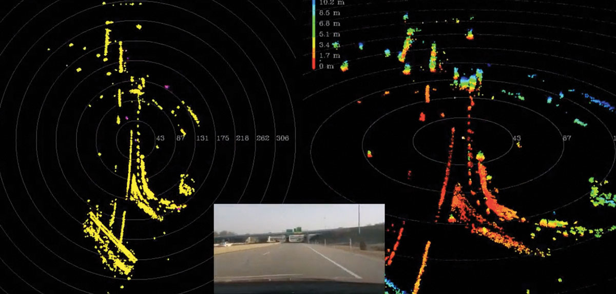
street view of a driving car (center). At right, the same view is shown with high-resolution radar, with 400+ m of range with precise Doppler/point in all weather conditions. At left, is the view using a standard lidar camera, which has >100 m of range, no Doppler and weather limitations. (Image: Oculii)
Radar with AI
Reliable sensors with AI software can enable autonomous functions by augmenting the hardware that is already in today’s vehicles. What makes this solution so exciting is that it does not require a design overhaul: the smart sensors in question fit within existing radar packaging.
Augmenting radar hardware with AI can significantly improve performance while reducing the cost to the consumer. This formula — better performance at a lower price tag — has the potential to greatly accelerate the speed with which AVs make it safely to the consumer market and to revolutionize the automotive industry.
Rather than pushing forward with the development of costly alternatives that are prohibitively expensive for the consumer market, intelligent radar sensors can bring AVs to the road sooner and for more drivers.
Steven Hong is the founder and CEO of Oculii, a high-resolution radar company enabling the next generation of autonomous systems. Powered by AI, Oculii software increases the resolution of commodity radar hardware by up to 100 times and works in any environment.
By Ethan Sorrelgreen Chief Product Officer, Carmera
Ethan Sorrelgreen, Carmera
Since the early days of autonomous vehicles (AVs), maps — specifically, so-called “high-definition” maps — have played a critical role in their technology stack. Central to perception, localization and path planning, these highly detailed, highly precise maps provide vehicles a baseline understanding of the world around them, delivering key priors that form the basis of the AV’s navigational decision making.
These maps come with exacting standards: a 3D network graph, spatial accuracy within 10 centimeters, attribute support in the thousands, and so on. Additionally, with AV deployments becoming more frequent — covering broader, more complex driving domains — these requirements are growing ever more demanding.
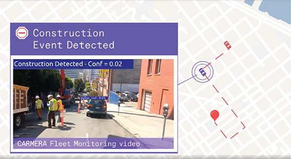
Of particular import is the increased need for temporal accuracy — that is, a map’s ability to represent current conditions (as opposed to conditions at some point in time). Roads — especially urban roads — are highly dynamic environments. Things like construction, repaving, signal upgrades and, now, on-street dining constantly affect the flow of traffic.
For example, in a summer 2020 survey of New York, Carmera found 88 drive-lane-impacting events (out of a total of 251 road events) over 72 hours in midtown Manhattan alone.
A map’s failure to reflect such events and changes can have a major impact on an AV’s reliability (Will the autonomous-driving feature remain engaged?), motion-planning (Will the AV safely and smoothly navigate through/around the obstacle?) and/or path planning (Will the AV choose the most efficient route despite the obstacle?). Maintaining a map, however, is exponentially more complicated than creating it. Not only does the data need to be good, it also needs to be fast and cheap to produce.
The key to solving the fast and cheap legs of this classic “good-fast-cheap” trilemma is simplifying the initial problem, using what Carmera calls a medium-definition map. If an HD map is a map with high feature detail and high spatial accuracy, then an MD map is a map with high feature detail but a slightly lower spatial accuracy. It essentially atomizes the dense, complex HD world into discrete, manageable blocks, or “zones.”
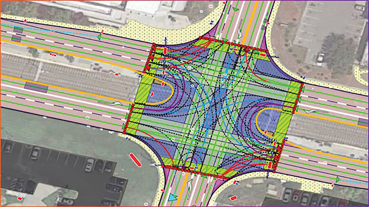
An MD map of a California intersection showing road features — including control attributes — placed with zonal accuracy. (Image: Carmera)
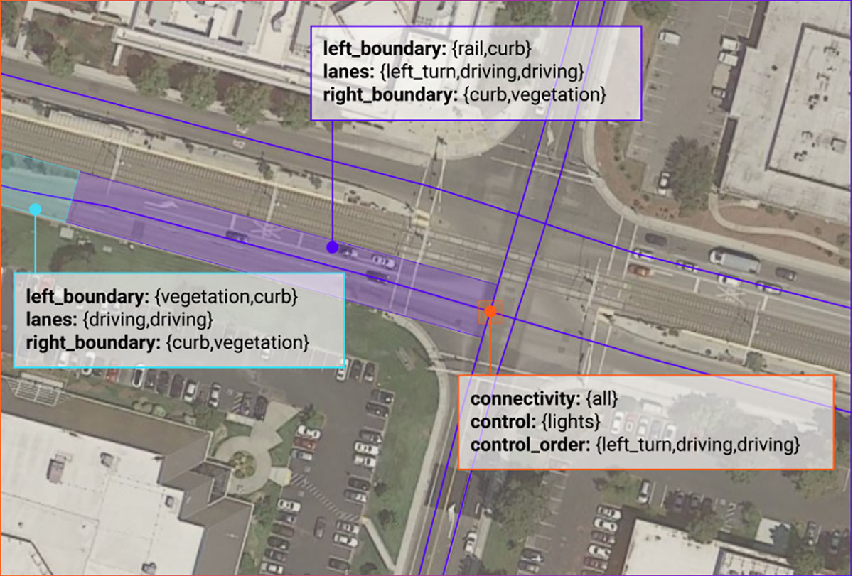
These zones — each a logical section of the road network — become the new unit of fidelity. The MD map catalogs all the features in a zone — a traffic light with a left arrow that controls the left two lanes, a bike path, a solid median, etc. — but not their precise location in the real world.
This simplified map provides the ideal basis for a system of triaging change, which dramatically lowers the cost — in both time and money — of HD map updates. Indeed, it provides the foundation for Carmera’s change-as-a-service offering — a modular, on-demand feed of road events and map updates that plug into existing consumer or HD maps.
Because of its lower spatial accuracy, an MD map can be updated with consumer-grade tools — a camera and a consumer-grade GNSS, let’s say — coupled with basic consumer vision algorithms. Contrast that to an HD map, which requires either expensive equipment, like a lidar rig, or — in Carmera’s case — sophisticated algorithms that can convert visual and telemetric data into HD road graphs.
MD map maintenance, therefore, is relatively cheap, which is good news for those who want to use MD data for next-generation consumer applications, such as natural-language navigation, or to support sub-L4 levels of automated driving (both excellent MD use cases).
An MD map of the same interaction, showing road features—including control attributes—placed with zonal accuracy. (Image: Carmera)
For HD updates, an additional pass is needed. Think of this as a tip-and-cue system: When a functional change in the map is detected (the tip), data from the identified zone is reprocessed using more complex algorithms to create the new HD vectors (the cue). In some cases — either because of customer requirements or because the change is superficial — a simple MD update may be sufficient. Thus, expensive computing resources are only deployed when needed.
This approach is equally effective for those using traditional lidar-based methods. There, the MD tip allows for targeted dispatching of lidar rigs, which results in significant cost-savings vis-à-vis the typical practice of sequential resurveying.
As technology evolves, so too will the role of the MD map.
Carmera sees a world where an AV’s onboard sensors will become so sophisticated that the HD maps’ utility may diminish. MD maps, however, will still provide vehicles key rules-of-the road relationships, helping optimize route planning and similar beyond-line-of-sight decision making. Employing this new standard now, therefore, not only makes driving safer today, it paves the way for the road ahead.
A roundup of recent products in the GNSS and inertial positioning industry from the June 2021 issue of GPS World magazine.
OEM
Grandmaster Clock
Multi-constellation receiver
Photo: Microchip
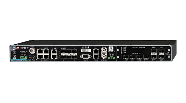
The upgraded TimeProvider 4100 2.2 is now more redundant and resilient. It provides secure, precise timing and synchronization for critical infrastructure such as 5G wireless networks, smart grids, data centers, cable and transportation services. The 4100 2.2 introduces a software-redundancy architecture for flexible deployment, and supports a new GNSS multi-band, multi-constellation receiver to protect against time delay from space weather, solar events and other disruptions. The 4100 2.2 offers options for software and hardware support.
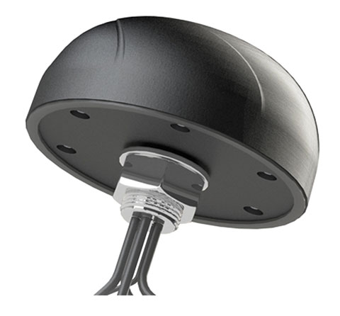
The NETZ 5-in-1 multiple-input and multiple-output (MIMO) solution combines two LTE antennas and two Wi-Fi antennas with a GNSS antenna for high data throughput and streaming, video, industrial and internet of things (IoT) applications. It offers a low-profile design with integrated SubMiniature version A (SMA) connectors and is designed with rugged PC+ABS plastic black housing for demanding environmental challenges.
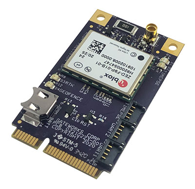
The GW16143 is a high-precision GNSS/GPS Mini-PCLe adapter card that provides precise positioning to applications using Gateworks single-board computers. Based on the U-blox ZED-F9P, the GW16143’s multi-band real-time kinematic (RTK) technology enhances convergence times and performance. The module receives GPS, GLONASS, Galileo and BeiDou; supports L1 and L2/L5 bands; and provides GNSS positioning accuracy
of <2 cm.
Tactical grade for higher order integrated applications
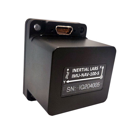
The IMU-NAV-100. (Photo: Inertial Labs)
The IMU-NAV-100 is a fully integrated inertial solution that measures linear accelerations, angular rates, and pitch and roll with high accuracy utilizing three-axis high-grade micro-electro-mechanical systems (MEMS) accelerometers and three-axis tactical-grade MEMS gyroscopes. It features continuous built-in test, configurable communications protocols, electromagnetic interference protection, and flexible input power requirements that allow it to be easily integrated in a variety of higher order systems. The IMU-NAV-100-S offers high performance stabilization for line-of-sight systems, motion-control sensors, and platform orientation and stabilization systems. The IMU-NAV-100-A is for GPS-aided INS, AHRS and motion reference units.
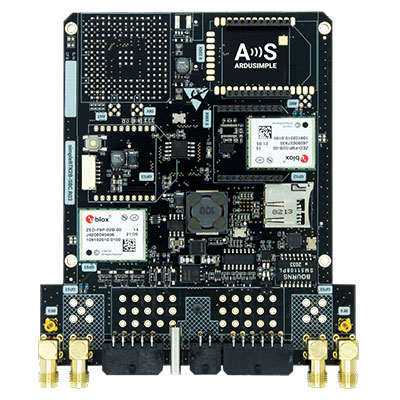
The SimpleRTK2B single-board computer is built around up to three u-blox ZED-F9P high-precision GNSS receivers to simplify development of centimeter-level positioning solutions supporting real-time kinematics (RTK). It was developed to make RTK technology as close to plug-and-play as possible, and make the technology accessible to broader audiences. In addition to working as a stand-alone solution, customers can program their own applications with the company’s microPython API. The SimpleRTK2B-SBC delivers mechanical integration with centimeter position on three axes (heading, pitch, roll), outputting on NMEA, RTCM, RS232 and CANBus interfaces via Ethernet, Bluetooth, Wi-Fi and 2G/3G/4G communication.
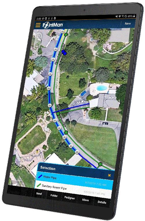
PointMan software is now integrated into the Vivax Metrotech vLoc3 with a GNSS real-time kinematic (RTK) receiver to create a utility-locate device. Using the RTK-Pro internal cellular module with 4G LTE capabilities, the operator can connect to the NTRIP RTK caster that provides RTCM 3 corrections. With the integration of PointMan with the vLoc3 RTK-Pro, critical buried infrastructure can be captured, recorded and displayed at survey-grade without additional external equipment or post-processing. The integration provides centimeter accuracy of the precise location of buried utilities in real time. Data collected includes the type of utility, the depth of cover and the utility’s precise location.
ProStar Holdings, prostarcorp.com
GIS platform
Geospatial and location intelligence for smart cities
Screenshot: Hexagon Geospatial
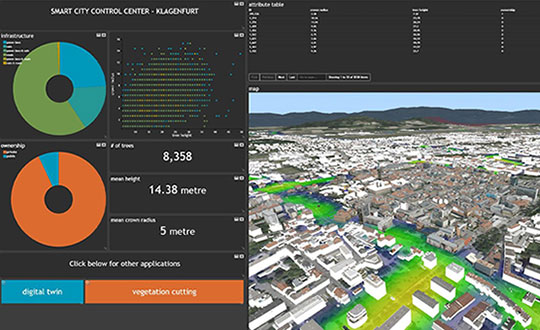
M.App Enterprise 2021 is a significant update to the platform for creating geospatial and location intelligence applications. The latest release features new browser-based 3D capabilities and enhanced visual effects, plus the ability to create and configure custom applications more easily. It allows users to access LuciadRIA’s 3D features with support for panoramic imagery, shading, ambient occlusion and other visualization effects to build browser-based solutions. It also features a new browser app configurator that makes it easier to create spatio-temporal dashboards, or Smart M.Apps. Feature Analyzer now allows users to add and manage multiple datasets on the fly and set up workflows.
Measures positioning, heading, attitude, velocity and heave
Photo: Hexagon | NovAtel
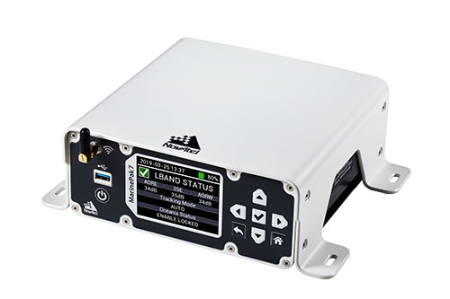
The MarinePak7 marine-certified GNSS receiver is designed for nearshore applications. The multi-constellation, multi-frequency receiver was engineered to receive the Oceanix Correction Service from NovAtel, providing horizontal accuracy up to 3 cm (95%) in a marine environment. With SPAN GNSS+INS technology capabilities, the MarinePak7 couples GNSS and inertial measurement units (IMUs) for 3D positioning.
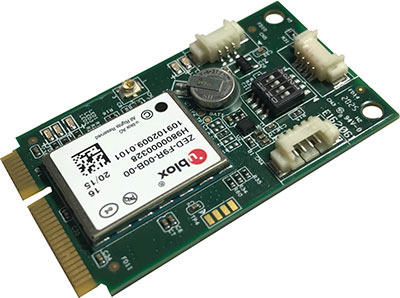
The ANNA-F9 high-precision GNSS Mini-PCIe card can achieve centimeter-level accuracy. It integrates the U-blox ZED-F9 receiver platform, providing multi-band GNSS (GPS, GLONASS, BeiDou, Galileo, QZSS and SBAS) and RTK positioning, and can be integrated with embedded systems. It provides high-accuracy positioning for applications including lane-level navigation and railway transportation. The ANNA-F9 series supports RTCM formatted corrections and centimeter-level positioning from local base stations or virtual reference stations in a network RTK setup.
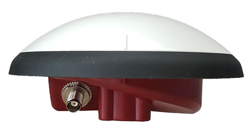
Marine vessels often host both Iridium (1616–1626.5 MHz) and Inmarsat (uplink: 1626.5–1660.5 MHz) satellite communication antennas that transmit and receive signals. The VSP6037L-MAR and VSP6337L-MAR VeroStar marine antennas strongly attenuate interference from both signal sources, providing 75 dB to 85 dB of attenuation over Iridium and 85 dB to 95 dB over Inmarsat uplink, enabling clean GNSS signal reception and precise positioning. The VSP6037L-MAR supports the full GNSS spectrum; the VSP6337L-MAR supports GPS/QZSS-L1/L2/L5, GLONASS-G1/G2/G3, Galileo-E1/E5a/E5b, BeiDou-B1/B2/B2a, and NavIC-L5 signals. Both antennas support L-band correction signals. Every VeroStar antenna features a robust pre-filter and a high-IP3 LNA architecture, minimizing desensing from high-level out-of-band signals, including 700 MHz LTE, while still providing a noise figure of 1.8 dB. They meet IEC 60945 and IEC 61108 marine certifications for challenging marine environments.
The managed internet of things (IoT) Acculink Cargo can track the location and condition of high-value and sensitive assets, providing real-time visibility, product-level tracking and exception-based monitoring as goods move through their supply chains. Tracking can be used to avoid delays, minimize dwell time, prevent theft and remediate environmental conditions that can cause asset damage.
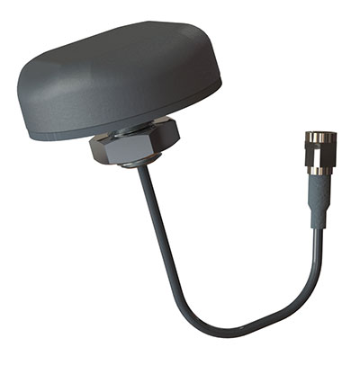
The GNS1559MPF or Mini GNSS is a rugged, high-performance and cost-effective solution for most GNSS or asset-tracking applications. The small form factor makes it easy to install on or in vehicles or buildings. It is IP67 rated to withstand impact as well as water and dust intrusion in demanding environments and operating conditions. The antenna can be configured with different cable types in varying lengths and with various connector types. Uses include public safety, in-building, fleet management, asset tracking, vehicle and personnel tracking.
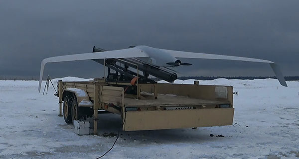
The Zala 421-16E5G long-flight UAS is a domestic unmanned aerial system with a hybrid power plant. The non-aerodrome-based system is capable of providing aerial monitoring covering distances of more than 150 kilometers and staying in the air for more than 12 hours. Its power plant charges a buffer battery for an hour, allowing the UAV to fly long distances. It is equipped with two thermal imagers and a 60x video camera. Alternatively, it can carry a payload of up to 10 kg.
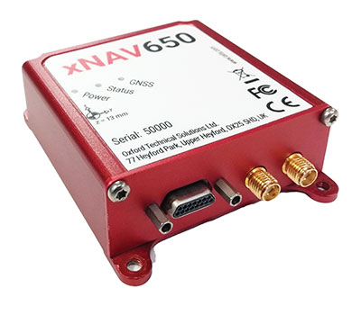
The xNAV650 inertial navigation system (INS) provides surveyors with absolute position, timing and inertial measurements (heading and pitch/roll) that they can integrate into their projects. When combined with data from other devices (such as lidar sensors and cameras), the INS measurements can greatly enhance the surveying process. The xNAV650 has the latest micro-electro-mechanical (MEMS) inertial measurement unit (IMU) technology and survey-grade GNSS receivers. At 77 x 63 x 24 mm and 130 grams, it is suitable for a wide range of UAV data-collection applications: surveys of bridges, buildings, forests and rail; coastal monitoring; map creation; and pipeline exploration. Data collected can be fused with data from almost any lidar sensor. OxTS NAVsuite software is included with all OxTS INS. Other optional software is available, including precision time protocol and GX/IX tight-coupling technology.
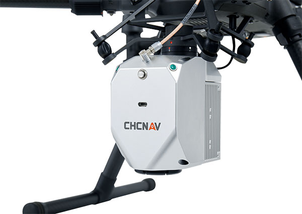
The AlphaAir 450 (AA450) lidar system is a lightweight, compact all-in-one sensor. Featuring an inertial measurement unit (IMU), GNSS receiver and 3D scanner and camera, the AlphaAir 450 is suitable for power-line inspections, topographic mapping, emergency response, agricultural work and forestry surveys. The unit can be rapidly deployed in the field to collect geospatial data. It achieves absolute accuracy of 5 cm (vertical) and 10 cm (horizontal) for small survey areas. Adjustment algorithms applied in CHCNAV CoPre software further improve precision and accuracy. The AA450 weighs 1 kilogram for easy mounting on a UAV. It is IP64 rated against dust and water spray and operates at –20° C to +50° C.
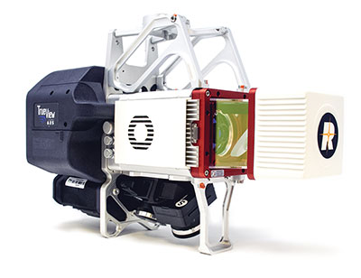
The True View 635/640 3DIS is GeoCue’s second-generation lidar/camera-fusion platform designed to generate high-accuracy 3D colorized lidar point clouds using the Riegl miniVUX-3UAV. All 3DIS platforms include GeoCue’s data-processing software suite True View EVO, which integrates with the Applanix POSPac. With its 120° fused field of view, the True View 635/640 provides 3D mapping with excellent vegetation penetration and wire detection in a payload package of 3.2–3.6 kg. True View EVO supports the direct creation of ground classified point clouds, surface models, contours, digital elevation models, volumetric analysis, wire extraction and similar products, without the need for additional third-party software.
Of the hundreds of papers researchers presented at the Institute of Navigation’s annual ION GNSS+ conference, which took place virtually Sept. 21–25, the following four focused on autonomous vehicle positioning for automobiles on city streets. The papers are available at www.ion.org/publications/browse.cfm.
Digital Maps with Tethered Positioning
The authors propose a new method for tight integration of digital map and dead-reckoning (DR) system (inertial measurement unit plus wheel odometer) to provide reliable navigation solutions in challenging GNSS environments for extended periods. Integrated DR and GNSS have been widely used as the backbone of any navigation system for the internet of things (IoT) and vehicle navigation applications. Dollar-level micro-electro-mechanical system (MEMS) inertial measurement units (IMUs) aided by vehicle-wheel odometers have been recently used as low-cost DR systems to bridge GNSS gaps in harsh environments, such as urban canyons, tunnels and under bridges.
However, DR drift errors rapidly increase over time and cannot satisfy most IoT and land-vehicle navigation requirements. Plus, the GNSS receiver may fail to provide accurate position or even experience a complete outage for more than 15 minutes, causing the tethered positioning error to reach several hundred meters. Because land vehicles are supposed to travel on roads, feedback from a digital map can be used to constrain their position.
The authors used a fuzzy-logic map-matching algorithm to identify the correct road segment on which the vehicle moves. A feedback filter senses a correct map-matched position as well as the road segment as measurement updates to the Kalman filter (KF) of the tethered positioning system. The proposed tight integration of digital maps and a DR system is evaluated using datasets collected by Profound Positioning Inc. in Calgary, Alberta, Canada. Results show the proposed method has an average of 0.15% of relative horizontal position error for Calgary datasets — a considerable improvement over the tethered-solution-only with 3.3% of relative horizontal position error. The average azimuth error of the proposed system is 1.3 degrees, while the tethered positioning system shows an average azimuth error of 9.7 degrees.
Citation. Yashar Balazadegan Sarvrood, Haiyu Lan, Aboelmagd Noureldin, Naser El-Sheimy and Profound Positioning Inc., Calgary, Alberta, Canada. “Tight Integration of Digital Map and Tethered Positioning and Navigation Solution for IoT applications and Land Vehicles.”
5G Signals for Opportunistic Navigation
This paper presents a navigation framework in which 5G signals are used for navigation purposes in an opportunistic fashion. A carrier-aided code-based software-defined receiver (SDR) produces navigation observables from received downlink 5G signals. The SDR produces navigation observables from 5G signals and a navigation filter in which the observables are processed to estimate the user equipment’s position and velocity.
An experiment was conducted on a ground vehicle to assess the navigation performance of 5G signals. In the experiment, the vehicle-mounted receiver navigated using 5G signals from two 5G base stations (also known as gNodeBs, or gNBs) for 1.02 km in 100 seconds. The proposed 5G navigation framework demonstrated a position root-mean-squared error of 14.93 m, while listening to signals from only two gNBs.
Citation. Ali A. Abdallah, Kimia Shamaei and Zaher M. Kassas, “Assessing Real 5G Signals for Opportunistic Navigation.”
Using Low-Cost Onboard Sensors
For autonomous vehicles, accurate positioning must be ubiquitous — reliably available at all times and in all places in which the vehicle is expected to operate. While GNSS commonly provides the basis for absolute positioning, it suffers from the problem of availability whenever a direct view of enough satellites is not possible. To address this failure mode, additional complementary sensors can be added to the overall navigation solution through a technique known as sensor fusion. Sensors such as inertial measurement units (IMUs), cameras, lidars, radar and more can be selected in such a way that the individual shortcomings of each sensor are mitigated, and the overall robustness and reliability are improved.
Although current autonomous-vehicle applications employ sensor-fusion techniques, they tend to rely on high-performance sensors to meet the accuracy requirements. These high-performance sensors tend to induce a much higher cost burden than would be acceptable for commercial production, and therefore make mass autonomy too expensive.
This paper focuses on using the lower cost sensors already available on most modern vehicles. These include low-resolution odometry and consumer-grade IMUs currently used for dynamic stability control and wheel-slip detection. A novel approach for combining vehicle speed, steering angles, transmission settings and multiple odometry inputs is presented along with achievable results while operating under a GNSS-denied environment. The test trajectory mimics a typical parking structure with many corners and short, straight segments. The only a priori information required for the filter is the wheel track and wheelbase (separation distance of the wheels).
A 90% performance improvement compared to the stand-alone GNSS/INS solution was observed during GNSS outages of up to 30 minutes. Furthermore, up to a 50% improvement was observed when comparing the multi-odometry to the single-odometry outages during the same 30-minute outage condition. Beyond GNSS outage performance, this paper shows how the use of the extra input to the filter can improve the positioning system’s protection levels to allow for more frequent engagement of the autonomous navigation system.
Citation. Ryan Dixon, Michael Bobye, Brett Kruger and Jonathan Jacox, “GNSS/INS Sensor Fusion with On-Board Vehicle Sensors.”
Radar and INS/GNSS
An autonomous vehicle requires a ubiquitous, accurate, precise and reliable localization system. Many sensors can be used for positioning and navigation, each with its strengths and weaknesses. Inertial measurement units (IMU) are usually used to build inertial navigation systems (INS). INS can be accurate for short durations; however, an INS accumulates errors and loses its accuracy quickly, especially when using low-cost MEMS-based sensors. GNSS can provide an absolute position and velocity to update the INS over time. A barometer provides absolute elevation information, and an odometer provides a speed update.
An integrated navigation solution consisting of an IMU, a GNSS-RTK receiver and odometer can perform well in open-sky areas and on highways. This system can achieve lane-level accuracy most of the time based on the condition of the sensors and the quality of the measurements. However, in downtown and urban environments, the degradation, multipath and blockage of the GNSS signal leads to poor performance for such an integrated navigation system, which is challenged to maintain lane-level positioning.
This paper presents a version of AUTO (formerly known as Coursa Drive), a real-time integrated navigation system that provides an accurate, reliable, high-rate and continuous navigation solution for autonomous vehicles by integrating INS, RTK GNSS, odometer and radar sensors with TomTom’s HD Maps. AUTO performs a tight nonlinear integration of the radar data and maps with the INS/GNSS/odometer system.
Results demonstrate that radar measurements and HD Maps can be tightly integrated with INS/GNSS in an effective manner, such that the integrated system can provide a high-rate, accurate, reliable and robust navigation solution. This is a crucial requirement for realizing a fully autonomous vehicle that can operate in urban environments under a wide range of conditions, including adverse weather and lighting conditions, even in downtown areas with degraded or denied GNSS signals.
Citation. Abdelrahman Ali, Billy Chan, Amr Shebl Ahmed, Medhat Omr, Dylan Krupity, Qingli Wang, Amr Al-Hamad, Jacques Georgy and Christopher Goodall, “Tight Coupling Between Radar and INS/GNSS with AUTO Software for Accurate and Reliable Positioning for Autonomous Vehicles.”
DDK Positioning solutions use the Iridium satellite constellation to deliver 5-cm GNSS accuracy to industrial users of the internet of things (IoT).
Iridium Communications Inc. has made a strategic investment in DDK Positioning, an Aberdeen, Scotland-based provider of enhanced GNSS accuracy solutions.
DDK uses the Iridium network to provide global precision-positioning services that can augment GNSS constellations, including GPS and Galileo, to significantly enhance their accuracy for critical industrial applications.
DDK is developing similar services for other GNSS constellations, such as GLONASS and Beidou. Terms of the investment are not being disclosed.
Standard positioning accuracy through a system like GPS is typically within 10 meters; however, by using the Iridium network, DDK’s enhanced GPS accuracy service brings incredibly precise positioning of 5 cm or less. This advanced level of accuracy is suitable for autonomous vehicles such as UAVs, precision agriculture applications, offshore infrastructure projects such as wind-farm construction, automotive applications like driverless cars, as well as a host of construction, mining, surveying and IoT use cases.
Historically, there have been limited geostationary satellite provider options for this type of service, but they suffer from line-of-sight blockage issues and coverage limitations in and around Arctic and Antarctic regions.
“We are delighted to have embarked on this journey with such a strong and well-respected company as Iridium,” said Kevin Gaffney, CEO of DDK Positioning. “This partnership is a perfect fit for DDK Positioning. With Iridium’s satellite communications network and our GNSS solution, we are in a position to deliver a truly unique service which is robust, resilient and secure. The investment made by Iridium will also allow us to grow the company even further whilst expanding our service offering globally.”
According to a report published by the European GNSS Agency, augmentation services like those offered by DDK will account for $76.5 billion (€65 billion) in global GNSS market revenue by 2029, while the global GNSS downstream market, including services delivered and hardware devices, is estimated to reach $382 billion (€325 billion).
“We are impressed with the team that DDK has put together and see great potential for this technology and how it takes advantage of the Iridium network,” said Iridium CEO Matt Desch. “DDK’s enhanced positioning is a unique capability that adds a high-value solution on top of our existing portfolio of custom network services. Solutions from Iridium and DDK partners that are focused on precision agriculture, autonomous systems, maritime and infrastructure projects can now experience incredibly precise GNSS accuracy from anywhere on the planet.”
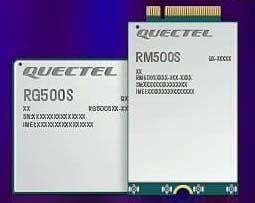
Quectel Wireless Solutions, a global supplier of modules for the internet of things (IoT), has announced the release of two new 5G New Radio (NR) module series, the RG500S and RM500S.
Based on the new Qualcomm 315 5G IoT Modem-RF System, both modules can support customers in building dedicated 5G devices for a variety of verticals including industrial IoT, retail, smart energy, private 5G networks, and many others.
The RG500S and RM500S both integrate a multi-constellation GNSS receiver, which simplifies the product design and provides accurate positioning services for users.
Utilizing the powerful Qualcomm 315 5G IoT modem, the RG500S and RM500S support extended-life software maintenance, helping create long-lasting IoT devices for the duration of their life span. Offering seamless integration, the RM500S is pin-to-pin compatible with Quectel’s LTE Cat 4 module EM05, Cat 6 module EM06, Cat 12 modules EM12-G/EM12xR-GL, Cat 16 module EM160R-GL and 5G module RM500Q, which provides more competitive 5G solutions to the IoT market. These features will help accelerate the 5G IoT market in the industrial and consumer IoT segments with use cases across robotics, automation, intelligent manufacturing, energy distribution, precision agriculture, construction, and mining.
Photo: Quectel
The RG500S and RM500S modules support 5G NR sub-6GHz bands in stand-alone mode offering backward compatibility with LTE networks. With network slicing in stand-alone mode, the two modules are able to offer end-to-end traffic isolation for critical traffic, guaranteed data rates and bandwidth, and lower latency than in non-standalone mode, which meets the demands of ultra-reliability and service-level agreements of typical industrial and enterprise scenarios.
The two modules are embedded with rich interfaces and incorporate high-speed USB 3.0/3.1, PCIe 3.0, U(SIM), RGMII and more, making them suitable for diversified industrial and consumer 5G applications such as industrial routers, robots, automation, intelligent manufacturing, smart cities, energy distribution, precision agriculture, construction and mining.
“Quectel has long been collaborating with Qualcomm Technologies to support the enablement of the 5G market in IoT,” said Patrick Qian, CEO, Quectel. “Based on the latest Qualcomm 315 5G IoT modem, the RG500S and RM500S are able to offer greater possibilities for the industrial and commercial IoT verticals. Features such as high performance and low latency as well as extended life software maintenance address the existing IoT market needs and can power a range of new 5G IoT use cases.”
“The Qualcomm 315 5G IoT modem solution was introduced to stimulate and scale the 5G IoT industry and enable the transitions needed to make 5G for IoT a reality. This solution is pin-to-pin compatible with legacy modules, which can accelerate device development and commercialization and promote growth and expansion in the 5G IoT industry. Integrating Qualcomm Technologies’ purpose-built modem into Quectel’s RG500S and RM500S modules will help deliver 5G to the IoT industry across industrial and enterprise applications,” said Jeffery Torrance, senior vice president, product management, Qualcomm Technologies.
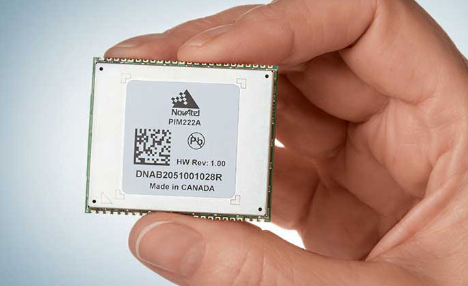
Hexagon | NovAtel has introduced the PIM222A, part of a new family of automotive GNSS positioning products for advanced driver assistance systems (ADAS) and autonomy. The PIM222A harnesses NovAtel’s decades of experience delivering precise positioning in demanding applications for mass deployment in ADAS applications and autonomous vehicles.
Built with automotive-qualified hardware in a package that is easy to integrate, the PIM222A leverages SPAN technology from NovAtel to provide accurate position data in urban environments that challenge GNSS availability. Deeply-coupled GNSS receivers and inertial measurement units (IMUs) ensure continuous availability of position, velocity and attitude, even when satellite signals are briefly blocked.
“I’m excited to introduce the PIM222A, truly the best of both worlds for high-performance GNSS and automotive standards,” said Gordon Heidinger, Segment Manager for Automotive and Safety Critical Systems. “It helps our customers jump-start their development activity for high-precision GNSS, fully supporting performance for all levels of autonomy, ADAS and positioning needs.”
The PIM222A, which was created in collaboration with STMicroelectronics, is a lightweight, power-efficient, solder-down module that maximizes flexibility for integration. The receiver design can be applied to low-, medium- and high-production volumes while retaining a rich array of features, including options such as multi-frequency, multi-constellation, RTK and dual-antenna precision.
The degree of slow-speed and initialization performance is maximized with the dual antenna feature, enabling the best possible positioning performance in all ADAS and autonomous driving situations.
Development kits for the PIM222A are available now for integrators in need of a positioning essentials solution for low- to high-quantity applications.
Using artificial intelligence (AI), the oneNav receiver improves accuracy and reliability for location-dependent applications and services.
A new L5-only GNSS receiver is now available from oneNav. The mobile receiver provides high location accuracy with half the footprint of existing solutions.
OneNav has signed a strategic partnership agreement with In-Q-Tel Inc., providing U.S. intelligence and defense agencies with a GNSS technology solution that is the first of its kind, according to the company. The company also closed a $21 million Series B funding round, led by GV, with participation from Norwest Venture Partners and GSR Ventures, bringing total funding to $33 million.
“Navigation satellite constellations are getting a major upgrade — L5 signaling. oneNav has built the first Pure L5 mobile receiver to leverage these modernized signals, and we will deliver our solution in a flexible licensing model, as a scalable and customizable IP core,” said Steve Poizner, co-founder and CEO of oneNav. “I’m proud to be working with such an outstanding team of GNSS experts, as well as our top-notch investors GV, Norwest and GSR.”
“Pure L5 is a more cost-, size- and power-efficient method to enable the benefits of modernized signals compared to current hybrid solutions,” added Paul McBurney, oneNav co-founder and CTO.
Other GNSS solutions that fuel location-based services — rideshare, smartphone navigation and 911 emergency calls — depend on L1 satellite signals developed in the 1970s. According to oneNav, legacy L1 systems can have significant accuracy deficiencies, especially in dense urban areas, placing users on the wrong side of the street or on the wrong block.
L1 signals are also susceptible to jamming. Recently, satellite constellations have been upgraded with state-of-the-art L5 signaling. L5 enables higher accuracy, broadcasts in a protected frequency band, has modern error correction and is transmitted at higher power.
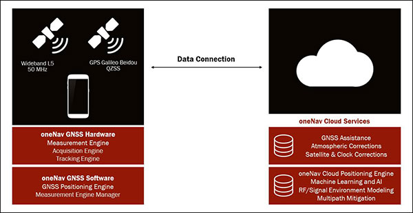
OneNav’s Pure L5 solution is built from the ground up to fully leverage modernized L5 signals from the GPS, Galileo, Beidou and QZSS navigation satellite constellations. Unlike current L1+L5 hybrid solutions that must first acquire on L1, oneNav’s Pure L5 solution both acquires and tracks on the new L5 signals, without L1 aiding, thereby taking full advantage of L5 benefits.
By eliminating the need for L1 circuitry, oneNav cuts GNSS RF size, power and cost in half. Supercharged by AI/machine learning, oneNav Pure L5 delivers much higher accuracy, even in challenging areas such as urban canyons. OneNav Pure L5 is ideal for highly space-constrained devices such as smartphones, wearables and IoT tracking modules. The solution is delivered in a semiconductor IP license package that includes register-transfer level (RTL), software and reference designs that can be integrated into a system on a chip (SOC) or built as a discrete chip.
The oneNav L5 mobile GNSS system architecture. (Image: oneNav)
Pure L5 Use Cases
OneNav’s technology will dramatically improve location-based services that are used every day by individuals across the world to pinpoint their location. Common use cases include:
Rideshare. Today’s mobile positioning technologies often place users on the wrong side of the street, or on the wrong block, making rideshare services very difficult to use. oneNav enables riders to more effectively match up with their drivers in downtown areas and other heavily blocked environments.
Smartphone Navigation. It is sometimes difficult to establish your exact location, or to determine which way to turn when using a mobile navigation application in a dense urban area. oneNav’s high availability and precise accuracy enables reliable turn-by-turn directions.
Emergency Calls. First responders need to accurately pinpoint the location of accidents in order to get to the right place quickly. oneNav’s reliable positioning and high accuracy get the right location information to ambulances, fire and police, enhancing public safety.
Asset Tracking. COVID-19 has increased the need for supply-chain assets to be transported and tracked with precision. oneNav enables accurate position reporting for asset tracking and other IOT applications.
“The mobile device industry — from phones to wearables — has made tremendous progress over the last 20 years,” said Karim Faris, GV general partner. “What’s surprising is that location-based services continue to have a significant margin of error, which can make all the difference when locating a rideshare passenger or pinpointing an emergency situation. With oneNav’s Pure L5 Mobile GNSS receiver, OEMs and application service companies will have the opportunity to provide their customers with state-of-the-art location-based services, driving competitive advantage.”