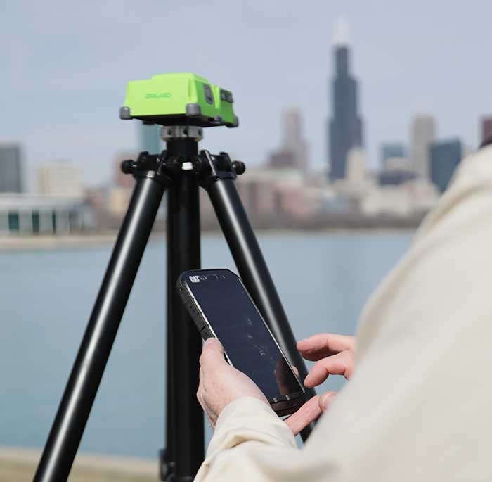
Depending on your age, 30 years represents a varying opinion of time. For some, it may seem like forever; for others, it may be a blink of an eye. In respect to technology, it can represent a complete change in the way we do things.
When we turned the calendar page to January 1990, our world had yet to experience the internet, the Hubble telescope had not been deployed to share its fantastic views, and The Simpsons television series was preparing to become the cartoon juggernaut it remains today.
Yes, lots has changed since 1990, and surveying is no exception.
Most professions look back through their history and see various periods where discoveries and inventions revolutionized how the work was completed.
For surveyors, the past 30 years have contained more advancements than all other years combined, with the greatest achievement being the global navigation satellite system (GNSS). With the United States leading the way with its Global Positioning System and the civilian ability to use this measuring system, modern surveying was forever changed.
Solar and lunar observations replaced
Before the implementation of a satellite navigation system, true global navigation was only computed using solar and lunar readings under specific conditions. GPS provided a new frontier for surveyors to establish positions without having to perform traversing from known points or collecting solar/lunar observations.
As the constellation grew, it became easier to use GPS to gain initialization for accurate and redundant position determination. As processor speeds and data storage capability increased, real-time kinematic (RTK) observations became the norm for surveyors everywhere.
The Russian satellite constellation, GLONASS, began operating fully in the late 1990s, and is now included to create today’s GNSS. More satellites provide more coverage, which in turn means more data collection potential.
Many nations and regions are building their own constellations to augment the current GNSS lineup, and also to safeguard the ability to obtain geographic locations when other systems are not available.
Bathymetric surveys made easy
GNSS capability and integration revolutionized several aspects of surveying, including a new and more reliable way of performing bathymetric surveys over large bodies of water. Computerized depth sounders were programmed to coincide readings with GNSS data collection to provide a more accurate and precise method of hydrographic surveying.
The past decade has continued the reliance on GNSS technology with many more devices and applications — not just for the surveyor, but for the public as well. While surveyors are using GNSS receivers on unmanned vehicles such as UAVs and boats, satellite navigation has infiltrated into many of our everyday routines. Cellphones, fitness trackers and our automobiles use this technology to guide us to our destinations.
Surveyors have used the GNSS revolution to create a digital world for better data collection, asset management and increased efficiency. Much has changed in 30 years for the surveyor and the world around us, so we should not be surprised about what technology will bring us next.
Hexagon’s Autonomy and Positioning division has launched its first autonomy positioning and sensing kits for the agriculture market and validated these solutions in its new autonomous research and development tractor.
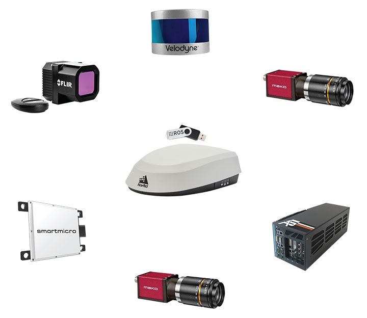
Through collaboration between NovAtel and AutonomouStuff, both part of Hexagon, the autonomous positioning and sensing kits were developed as part of Hexagon’s Smart Autonomous Mobility solutions portfolio launched at CES in early 2020. NovAtel and AutonomouStuff created the solutions with agriculture machinery OEMs and robotic machinery manufacturers in mind.
As a demonstrator vehicle for Smart Autonomous Mobility, the autonomous tractor features object detection and classification, simultaneous relative localization and mapping, absolute positioning through GNSS technology, and localization sensor fusing. Built to illustrate the viability of new positioning and sensing kits, the tractor incorporates safety-critical learnings with situational and environmental awareness, and manual remote control when needed. This platform validates how these solutions and capabilities accelerate autonomous development.
Hexagon’s autonomous research and development tractor validated the new kit. (Photo: Hexagon)
The positioning and sensing kits are optimized for autonomous agriculture applications, including products like the Smart7 antenna and autonomous robotic capabilities through the NovAtel OEM7 driver powered by the Robot Operating System (ROS). The kits also feature TerraStar GNSS Correction Services, ALIGN heading and relative positioning firmware, and SPAN GNSS+INS technology. Though designed for agriculture, the kits integrate seamlessly into other off-road autonomy applications.
“These positioning and sensing kits provide developers with technology bringing assured positioning to autonomy in agriculture,” explained Michael Martinez, agriculture segment manager at Hexagon | NovAtel. “Robotic-machinery manufacturers or those experienced in autonomy may be unfamiliar with the unique challenges facing agriculture applications. Conversely, those experienced with agriculture may not have the expertise to integrate positioning and sensing products within autonomous solutions. We can help in both cases through these positioning and sensor kits, as demonstrated by our autonomous tractor.”
The new autonomous positioning and sensing kit. (Photo: Hexagon)
“We’re excited to use this tractor as a platform to validate the human identification, obstacle detection and enhanced environmental awareness that our sensing kits add to our assured positioning solutions in agriculture,” said John Buszek, VP of products and services at Hexagon | AutonomouStuff. “The sensing and positioning technologies we’ve integrated on this demonstration platform showcase the Smart Autonomous Mobility portfolio, which enables and accelerates the development of autonomy in agriculture applications from prototyping to production.”
For more than 30 years, NovAtel has delivered GNSS positioning solutions as a trusted provider for top precision agriculture companies. Combined with AutonomouStuff’s decade of expertise in autonomy and sensor fusion, they significantly reduce the barrier of entry into autonomy to accelerate the time to market for autonomous solutions in agriculture, construction, mining and other off-road applications.
Learn more about their agriculture autonomy capabilities by taking a virtual tractor tour via their 3D interactive app or online at novatel.com/ag-autonomy.
Northrop Grumman Corporation has successfully completed the critical design review (CDR) milestone for the Embedded Global Positioning System/Inertial Navigation System (INS)-Modernization, or EGI-M, program.
EGI-M provides state-of-the-art airborne navigation capabilities with an open architecture that enables rapid responses to future threats. The fully modernized system integrates new M-code capable GPS receivers, provides interoperability with civil controlled air space, and implements a new resilient time capability.
“The completion of this milestone is a key step in bringing necessary navigation capability upgrades to our warfighters,” said Brandon White, vice president, navigation and positioning systems, Northrop Grumman. “With its open architecture and government ownership of the key internal interfaces, EGI-M’s next-generation navigation solution allows the government to quickly insert emerging capabilities from third parties while maintaining cyber security and airworthiness.”
The F-22 is one of the lead platforms for EGI-M integration. (Photo: Staff Sgt. Carlin Leslie/U.S. Air Force)
Northrop Grumman’s unique, modular platform interface design enables backwards compatibility with existing platform footprint and interfaces (A-Kits), allowing current platforms to easily integrate and deploy Northrop Grumman’s EGI-M solution.
At the same time, EGI-M’s modular software and hardware, coupled with government ownership of key interfaces, allows EGI-M to benefit from rapid upgrades with best of breed software and hardware technologies now and in the future.
Northrop Grumman has been on contract for the engineering and manufacturing development (EMD) phase of EGI-M since November 2018. The CDR milestone marks the completion of detailed hardware and software design of the EGI-M product line.
The launch platforms for Northrop Grumman’s EGI-M are the F-22 fighter jet and E-2D early warning aircraft. Additional fixed-wing and rotary-wing platforms across Department of Defense and allied forces have already selected Northrop Grumman’s EGI-M as their future navigation solution.
The E-2D Hawkeye is an American all-weather, carrier-capable tactical airborne early-warning aircraft. (Photo: U.S. Navy)
To get the best measurements of Earth’s atmosphere, you sometimes have to leave it. This November, the Sentinel-6 Michael Freilich spacecraft will do just that.
News from the Jet Propulsion Laboratory
When a satellite by the name of Sentinel-6 Michael Freilich launches this November, its primary focus will be to monitor sea-level rise with extreme precision. But an instrument aboard the spacecraft will also provide atmospheric data that will improve weather forecasts, track hurricanes and bolster climate models.
“Our fundamental goal with Sentinel-6 is to measure the oceans, but the more value we can add, the better,” said Josh Willis, the mission’s project scientist at NASA’s Jet Propulsion Laboratory in Southern California. “It’s not every day that we get to launch a satellite, so collecting more useful data about our oceans and atmosphere is a bonus.”
A U.S.-European collaboration, Sentinel-6 Michael Freilich is one of two satellites that compose the Copernicus Sentinel-6/Jason-CS (Continuity of Service) mission. The satellite’s twin, Sentinel-6B, will launch in 2025 to take over for its predecessor. Together, the spacecraft will join TOPEX/Poseidon and the Jason series of satellites, which have been gathering precise sea-level measurements for nearly three decades. Once in orbit, each Sentinel-6 satellite will collect sea-level measurements down to the centimeter for 90% of the world’s oceans.
JPL-developed instrument
Meanwhile, they’ll also peer deep into Earth’s atmosphere with GNSS-RO to collect highly accurate global temperature and humidity information. Developed by JPL, the spacecraft’s GNSS-RO instrument tracks radio signals from navigation satellites to measure the physical properties of Earth’s atmosphere. As a radio signal passes through the atmosphere, it slows, its frequency changes, and its path bends. Called refraction, this effect can be used by scientists to measure minute changes in atmospheric physical properties, such as density, temperature, and moisture content.
The precise global atmospheric measurements made by Sentinel-6 Michael Freilich will complement atmospheric observations by other GNSS-RO instruments already in space. Specifically, the National Oceanic and Atmospheric Administration’s National Weather Service meteorologists will use insights from Sentinel 6’s GNSS-RO to improve weather forecasts.
Also, the GNSS-RO information will provide long-term data that can be used both to monitor how our atmosphere is changing and to refine models used for making projections of future climate. Data from this mission will help track the formation of hurricanes and support models to predict the direction storms may travel. The more data we gather about hurricane formation (and where a storm might make landfall), the better in terms of helping local efforts to mitigate damage and support evacuation plans.
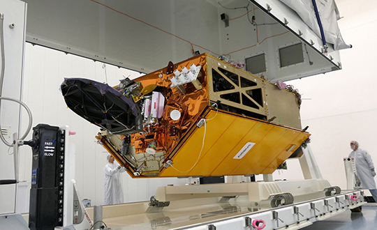
The Sentinel-6 Michael Freilich spacecraft undergoes tests at its manufacturer Airbus in Friedrichshafen, Germany, in 2019. The white GNSS-RO instrument can be seen attached to the upper left portion of the front of the spacecraft. (Photo: Airbus)
A brief history of radio occultation
Radio occultation was first used by NASA’s Mariner 4 mission in 1965 when the spacecraft flew past Mars. As it passed behind the Red Planet from our perspective, scientists on Earth detected slight delays in its radio transmissions as they traveled through atmospheric gases. By measuring these radio signal delays, they were able to gain the first measurements of the Martian atmosphere and discover just how thin it was compared to Earth’s.
By the 1980s, scientists had started to measure the slight delays in radio signals from Earth-orbiting navigation satellites to better understand our planet’s atmosphere. Since then, many radio occultation instruments have been launched; Sentinel-6 Michael Freilich will join the six COSMIC-2 satellites as the most advanced GNSS-RO instruments among them.
“The Sentinel-6 instrument is essentially the same as COSMIC-2’s. Compared to other radio occultation instruments, they have higher measurement precision and greater atmospheric penetration depth,” said Chi Ao, the instrument scientist for GNSS-RO at JPL.
GNSS-RO basics
The GNSS-RO instrument’s receivers track navigation satellite radio signals as they dip below, or rise from, the horizon. They can detect these signals through the vertical extent of the atmosphere — through thick clouds — from the very top and almost all the way to the ground. This is important, because weather phenomena emerge from all layers of the atmosphere, not just from near Earth’s surface where we experience their effects.
“Tiny changes in the radio signal can be measured by the instrument, which relate to the density of the atmosphere,” said Ao. “We can then precisely determine the temperature, pressure, and humidity through the layers of the atmosphere, which give us incredible insights to our planet’s dynamic climate and weather.”
With the help of JPL’s GNSS-RO principal investigator Chi Ao and NOAA’s National Weather Service meteorologist Mark Jackson, this video explains how the GNSS-RO instrument aboard Sentinel-6 Michael Freilich will be used by meteorologists to improve weather forecasting predictions. (Credit: NASA/JPL-Caltech)
But there’s another reason why probing the entire vertical profile of the atmosphere from orbit is so important: accuracy. Meteorologists typically gather information from a variety of sources – from weather balloons to instruments aboard aircraft. But sometimes scientists need to compensate for biases in the data. For example, air temperature readings from a thermometer on an airplane can be skewed by heat radiating from parts of the aircraft.
GNSS-RO data is different. The instrument collects navigation satellite signals at the top of the atmosphere, in what is close to a vacuum. Although there are sources of error in every scientific measurement, at that altitude, there’s no refraction of the signal, which means there’s an almost bias-free baseline to which atmospheric measurements can be compared in order to minimize noise in data collection.
And as one of the most advanced GNSS radio occultation instruments in orbit, said Ao, it will also be one of the most accurate atmospheric thermometers in space.
More on the mission
Copernicus Sentinel-6/Jason-CS is being jointly developed by the European Space Agency (ESA), the European Organisation for the Exploitation of Meteorological Satellites (EUMETSAT), NASA, and the National Oceanic and Atmospheric Administration (NOAA), with funding support from the European Commission and support from France’s National Centre for Space Studies (CNES).
The first Sentinel-6/Jason-CS satellite that will launch was named after the former director of NASA’s Earth Science Division, Michael Freilich. It will follow the most recent U.S.-European sea-level observation satellite, Jason-3, which launched in 2016 and is currently providing data.
NASA’s contributions to the Sentinel-6/Jason-CS mission are three science instruments for each of the two Sentinel-6 satellites: the Advanced Microwave Radiometer, the GNSS-RO, and the Laser Retroreflector Array. NASA is also contributing launch services, ground systems supporting operation of the NASA science instruments, the science data processors for two of these instruments, and support for the international Ocean Surface Topography Science Team.
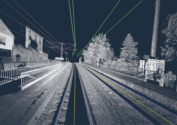
Innovate UK, the United Kingdom’s innovation agency, has selected Hexagon’s Geospatial division to conduct a research project that will result in faster and higher-precision mapping of railway infrastructure through the use of artificial intelligence.
The project is funded by Network Rail, the owner and operator of Great Britain’s railway infrastructure, under its R&D portfolio and delivered by Innovate UK through the SBRI competition, Innovation in Automated Survey Processing for Railway Structure Gauging, Phase One. A small group of teams was selected for this effort.
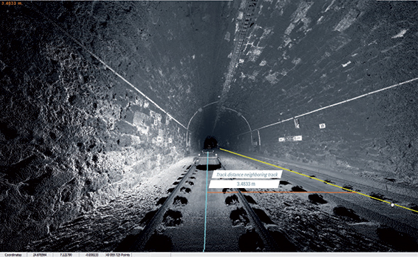
Image: Hexagon
The project will enable Network Rail to automatically identify and measure railway structures from lidar data, saving valuable time and resources, while also improving planning and operations across the rail network. The current, manual process takes analysts months or even years due to the size of the data and the labor-intensive tasks involved.
“The combination of cross-sectional area, shape, length and speed all place a space requirement on today’s railway,” said James Sweeney, senior engineer at Network Rail. “We anticipate this project will offer us a more efficient way to capture, analyse and measure railway features along 20,000 miles of track, which is important to railway safety and the growth and capacity of our network.”
Network Rail collects detailed information about its track and the surrounding features, such as bridges and tunnels. The data is then analyzed to assess clearances between trains and the infrastructure around them, which is key to safety.
Image: Hexagon
The new project aims to automate the extraction and calculation of railway features from sensor data, leveraging AI to automatically analyze point-cloud data, identify different structure types, and perform measurements on the structures. The data will be collected from reality capture solutions from Hexagon’s Geosystems division.
“Network Rail, supported by Innovate UK, is leading the way in the use of AI to automate rail structure identification and measurement,” said Mladen Stojic, president of Hexagon’s Geospatial division. “We are excited to be part of a project that can help transform the gauging process for UK railways.”
The collaboration will provide designers with a power-efficient, high-accuracy GPS solution for battery-operated devices without the additional cost of a dedicated GNSS chip.
“Today’s advanced navigation systems are facing unique challenges when being implemented in power-constrained IoT devices,” said Ambroise Popper, CEO at Nestwave. “By combining Nestwave’s low-power geolocation software with Synopsys’ efficient ARC IoT Communications IP Subsystem, we can deliver a geolocation solution that offers greater accuracy, lower power consumption, and lower cost compared to existing GNSS solutions.”
Ultra-low bandwith IoT applications
The ARC IoT Communications IP Subsystem is an integrated hardware and software solution that combines Synopsys’ DSP-enhanced ARC EM9D processor, hardware accelerators, dedicated peripherals and RF interface to deliver efficient DSP performance for ultra-low bandwidth IoT applications.
Nestwave’s GNSS solution takes advantage of the ARC EM9D processor’s efficient DSP capabilities and ability to add dedicated hardware accelerators or custom instructions using APEX technology to reduce frequency requirements, giving customers additional performance bandwidth.
The ARC EM9D processor is supported by the MetaWare Toolkit, which includes a rich library of DSP functions, allowing software engineers to rapidly implement algorithms from standard DSP building blocks.
Geolocation for emerging applications
Nestwave has developed an ultra-low power, advanced GNSS solution for use in IoT applications. When integrated with an IoT modem such as NB-IoT, Cat M1, LoRa or Sigfox, the solution offers low-cost geolocation for emerging applications such as asset tracking, smart factories, and smart cities, without the need for an external GNSS chip.
“Emerging IoT applications are demanding geolocation functionality with high-accuracy and ultra-low power consumption,” said John Koeter, senior vice president of marketing and strategy for IP at Synopsys. “The combination of Synopsys’ ARC IoT Communications IP Subsystem with Nestwave’s GNSS technology will help designers significantly improve geolocation performance, reduce frequency requirements and lower overall power consumption for battery-powered IoT applications.”
A GNSS jamming trial will take place from Sept. 8 through Dec. 4 in and around Luce Bay, at Wigtownshire in southern Scotland, conducted by the United Kingdom’s Civil Aviation Authority.
The trial will affect electronic situational awareness devices, UAS command systems and GNSS receivers.
The activity may affect GNSS receivers along with UAS and cockpit devices operating on 433, 868, 915, 2400, 5800 MHz operating up to 40,000FT AMSL within 55NM of 545020N 045548W (West Freugh).
During the trials, impacted systems may suffer intermittent or total failure. Individual events will not exceed two minutes in duration with no more than five events per hour. Activity will take place in the daytime hours between 0830 and 1600.
The European GNSS Agency (GSA), in collaboration with the Council of European Geodetic Surveyors (CLGE), has launched the Geomatics on the Move 2020 competition. The event aims to foster the use of European Union (EU) satellite programs Galileo, EGNOS and Copernicus among students, young professionals, entrepreneurs and small and mid-sized businesses to create innovative geomatics applications and solutions across all over Europe.
Building and expanding on the CLGE Student Contest, which has been held for the past nine years, the new Geomatics on the Move Prize Contest targets applications that integrate the use of additional technologies such as artificial intelligence, machine learning, augmented and virtual reality, as well as supplementary remote sensing data sources like drones, GSA said. Solutions animated through mobile phone applications or other easy-to-use platforms are also accepted.
“This is the ninth year of partnership between the Council of European Geodetic Surveyors and the GSA; over the years we have seen some exciting and innovative solutions emerge that leverage the EU Space Programme to deliver practical solutions for the mapping and surveying community,” said GSA Acting Executive Director Pascal Claudel. “This year, as we recover from this global setback, I look forward to seeing even more novel ideas — from all over the European Union — able to respond to current and future challenges.”
The competition will be organized in two stages. The first phase is an open call for ideas, during which applicants submit posters describing their ideas. The deadline for these submissions is Oct. 16.
The proposals then will be evaluated by the GSA and CLGE, and a maximum of 10 projects will be chosen to present their pitch during the finals. The selected applicants will refine their poster and prepare their pitch, for which technical support and training will be made available.
The official award of the Geomatics on the Move prize contest will take place virtually, during the European Space Week, taking place Dec. 7-11. During this event, finalists will present their solutions to the evaluation board, and winners will be announced on the official contest site.
With an overall prize of €30 000, a set of 10 prizes will be offered in two categories. The first of these categories targets EU space-based traditional geomatics solutions and the second targets integrated geomatics solutions. he first category is looking for solutions in which the main innovation is based on the use of EGNSS, employing traditional equipment such as surveying or GIS grade GNSS receivers for applications such as cadastral, marine and mining surveying or GIS mapping. The integrated geomatics category targets integrated surveying solutions that use Galileo or EGNOS and leverage cutting-edge tools and technologies such as drones, mobile mapping, laser scanners or augmented/,mixed reality, both within geomatics applications or beyond.
Our ongoing battle with COVID-19 has shown we can adapt to radical changes. A big, but worthwhile, change would be to convert our existing land databases to a cadastre system.
Any place that one may travel around the globe, they will find boundary lines that define properties and regions. For some countries, these parcels may be primarily owned by the government while in more developed nations, a large percent of the land is owned by private citizens.
These parcels, when looked at together, together create a large jigsaw puzzle that seemingly fits together perfectly. Visually, all the lines should fit snugly to their adjacent neighbor so that the sum of the parts equals the whole. This system, called a cadastre, has many redeeming qualities and makes for an efficient choice of keeping an inventory of a region or country’s parcels and infrastructure.
Origins of the cadastre system
The cadastre system of parcel registration is the database of choice for determining land ownership and taxes on property through much of the developed world. Most of the places where this system of parcel registry consists of centralized governments usually have more oversight and legislative power than more “free” countries like the United States.
Also, these countries in which these systems exist are typically small and/or have a manageable number of parcels so the development of the cadastre is much more controlled and maintained.
To help us understand the origin of this parcel system, let us explore the background of cadastre and its beginnings:
Definition: an official register of the quantity, value, and ownership of real estate used in apportioning taxes Origin: Mid-19th century from French, from cadastre ‘register of property’, from Provençal cadastro, from Italian catastro (earlier catastico), from late Greek katastikhon ‘list, register’, from kata stikhon ‘line by line’. (Source: Merriam-Webster.com)
In the years after the fall of the Roman Empire and through the end of many feudal societies, land ownership was transferred to individuals and families with the expectation of paying a tax to the government for this opportunity. Landowners could plant and harvest their own crops, raise farm animals for labor, and provide various goods and services to the community.
Besides a small fee for conveyance, the government would ask for a “meager” tax to be paid regularly. Land that was sold to these individuals was recorded in a “cadastre” for tracking of ownership and tax payment. These records were primitive in nature and relied heavily on associating a parcel number to the owner versus an actual legal description to describe the property.
It was not until more sophisticated and elaborate surveying instruments were developed that physical descriptions of the land were used to determine boundaries.
Cadastre system gives way to legal descriptions
This cadastre system of parcel management continues to exist in modern times in many parts of the world with one notable exception: The United States. Some will equate our parcel indexing system as being a traditional cadastre, but this numbering procedure is secondary to the means and methods of parcel conveyance in the U.S.
For the non-surveyor reader, in the U.S. over the past few centuries a multitude of land systems have been used to establish parcel boundaries , each with their own unique system of describing land and conveyances. These types of land transactions began after the establishment of the colonial states and rapid expansion into previously unmapped territories.
The push westward across the country introduced the Public Land Survey System (originated by Thomas Jefferson) and established sectional land divisions. As we encountered (and acquired) new territories, including the Louisiana Purchase and Texas, existing land measuring units and description methods were maintained to preserve these systems. No matter how the parcels are described, we rely heavily on the grantor/grantee system of transfer of ownership and rights throughout most of the country, with parcel numbering being applied post-transaction.
So why is the grantor/grantee system the weak link in the chain of parcel establishment and conveyance? Many times, it comes down to the legal description and how it was created. Our system allows for the creation of a parcel by varying means by the professional land surveyor. The biggest issues occur when parcels are defined by a metes and bounds description with little to no reference to adjoining property or known monuments.
When the legal descriptions of these parcels come into play, that is when the trouble starts, with calls made to attorneys and surveyors to help straighten everything out. To the common layperson who owns land or is looking to buy a parcel, it may seem unthinkable that parcels do not naturally fit seamlessly together with no gaps or overlaps. While the quality of survey data has increased in precision, the accuracy of marrying old data with the new suffers in many ways. How did we get to this point? Let us step back in the not-so-distant past to review how things have progressed throughout my short career.
Set the flux capacitor to the early 1980s…
Before computers and CAD, most agencies adopted a system of parcel and right-of-way mapping manually drafted on large sheets of durable paper or film. Depending on the municipality or county one was in, each sheet could represent either a quarter section (approximately 160 acres) or one half of a quarter section (approximately 80 acres) within a standard section of the Public Land Survey System (PLSS) established by the General Land Office (GLO) of the U.S. (now known as the Bureau of Land Management).
These maps were based upon standard measurements within the given quarter section and drawn using 90-degree corners at the edges of the sheet. The linework depicting the parcels within blocks and larger areas was drawn as close to scale as possible but was intended to be a graphic representation of the shape rather than an accurate reproduction. Considering the technology and measuring devices/capabilities of the time, these records were very helpful in performing retracement surveys of existing properties.
Because these surveys and parcel recordkeeping were performed long before computers, plotters, and CAD software became the norm, surveyors calculated and documented their work using manual computation and drafting from handwritten notes collected in the field. Not every parcel has 90-degree corners and lengths that are integers, so mapping departments for governmental agencies drafted new surveys and parcel boundaries to fit within the existing base sheets. Throw in the varying measurements from different surveyors and we have the real-life jigsaw puzzle that does not fit.
Because the aforesaid mapping departments produced parcel numbering after the creation and conveyance of the property, the damage is already done in conforming with adjacent properties. This is an important factor in the professional surveyor’s responsibility to protect the public when performing an original survey for a new parcel and/or subdivision and utmost care must be observed.
We have an army of land surveyors across the country shaping parcels to fit within a large jigsaw puzzle with an instruction sheet that must be strictly followed. One missed measurement or corner monument is in the wrong position, and we now have two or more parcels that will not fit together in the puzzle.
Many mapping professionals will point, however, to the geographical information system (GIS) and how it improved this convoluted method of parcel databases. But did it?
The digital spaghetti bowl
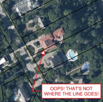
For a large part of the U.S. where a data-intensive GIS has been created and maintained, it is a step in the right direction, but it still lacks the overall efficiency of a cadastre. Very few GIS databases contain survey-grade parcel establishment on recognized horizontal and vertical datums. Most are parcels and roadways digitized from old mapping and records that are vague graphical representations at best.
One of the most important pieces of the GIS database are the base layers that contain control points and parcel/right-of-way lines that coincide with the datums that govern the region or state. Many governmental agencies do not employ a professional surveyor or surveying staff educated and trained to establish these datums within the database.
Incorrect GIS parcels information. (Image: Tim Burch)
Most times, the base layers are established “close enough” using aerial mapping and other data, including handheld GNSS receivers to collect infrastructure improvements. This is not a knock on these departments or individuals; they created the best possible database with the information on hand.
When merged with aerial mapping and/or survey-grade data, the graphical information from the archival records can be confusing and misleading, especially to those who are not educated to understand the data.
Is the cadastre an upgrade?
The reason to consider converting all the existing parcel mapping and subsequent infrastructure/improvement mapping to a cadastre are simple: technology. We have previously discussed cities building digital twins (“Surveying and Geospatial Data,” GPS World, July 2020) utilizing remote sensing and a multitude of GNSS-capable products.
Besides surveyors, many professions and trades use GNSS technology as a tool within their work environments. Our nation has experienced rapid growth in the last 150 years. The Industrial Revolution and the advancement of machinery, materials and building techniques have greatly impacted the ability to build more infrastructure and improvements. Many of these improvements and utilities have exceeded their useful life but have no timelines for replacement.
Developing accurate maps of this aging infrastructure will ensure a proper data set from which a replacement design can be made. Couple this ability to work in a geospatial environment with other datasets, including aerial/satellite photography and lidar acquisition, and it gives us a nearly unlimited ability to map our world in appropriate datums with greater accuracy and precision. Governmental agencies could utilize this system to monitor illegal activities (such as dumping, mining, unpermitted construction) and gauge environmental concerns (drainage issues, problematic runoff, deteriorating infrastructure) to better protect the public. This system could also be used to refine our property tax system and work towards a more equitable means of assessing our properties.
None of these potential changes and upgrades would have been possible 40-50 years ago; the invention and adaptation of GNSS have allowed these technologies to emerge. We continue to find new ways of measuring and mapping, so using these new techniques should be foremost on our minds to make these previous tedious tasks much easier to accomplish.
The hurdles to change
The biggest challenge, in my professional surveying opinion, will be adapting millions of parcels and deeds to a new database and applying them to the current datums. For instance, here is an example of potential (and recordable!) legal description:
“Beginning at the northeast corner of the parcel, said corner being the intersection of the south right-of-way line of Smith Street with the east right-of-way line of Jones Street; thence easterly on the said south line of Smith Street to the northwest corner of the Williams parcel per Deed No. 12345; thence southerly on the west line of said Williams parcel to the north right-of-way line of Main Street; thence westerly on the said north line of Main Street to the intersection with the said east right-of-way line of Jones Street; thence north on the said east right-of-way line of Jones Street to the point of beginning.”
Example of “bounds” legal description. (Image: Tim Burch)
While this is only a made-up example, it does represent a generally accepted legal description for parcel conveyance in most recording agencies. What does a mapping department do with this kind of legal description to place it accurately within a GIS or cadastre? Unless the four adjoining legal entities (Smith Street, Jones Street, Main Street, and the Williams parcel) exist geospatially within the database, the technician will have a tough time inserting this parcel into the records. Unless the entire surveying community is up to the challenge of working solely in an approved geospatial datum for all their work, much of this effort will not accomplish anything.
The other roadblock to converting our current systems to a cadastre is the rest of the parties who work with legal documents, plats, and infrastructure; they may not be up to the challenge for making a radical change for the better. From the assessor’s, recorder’s, and mapping offices to the title companies and attorneys, many have an attitude that the system is too big to revamp. Because they only work in one part of the overall system, they do not see the benefit of blowing it all up to make it a more robust and useful database.
Practically speaking…
Revamping of any system within the varying levels of government is costly, no matter what branch or region is discussed. Governmental agencies are being asked every day to do more with less and provide more value in their services with few numbers of staff.
While there may be a large upside to converting our existing databases to a cadastre, the downside is the effort and cost to do so. Yes, the new system would be scalable and easily adaptable for more infrastructure growth and could be expanded in an infinite number of ways. We can liken this proposed idea to converting all weights and measures to the Metric System: going metric will make lots of tasks and procedures easier, but flies in the face of everything we know as a society.
However, our ongoing battle with COVID-19 has shown we can adapt to radical changes. The cadastre is a better system, but I do not want another worldwide disaster to convince us to change.
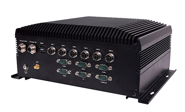
Lanner Electronics Inc., a designer and manufacturer of network appliances and intelligent edge computing platforms, has launched the R3S series of rugged, EN-50155-certified fanless vehicle/rail computers.
The R3S is equipped with a u-blox NEO-M8N module, which receives GPS, Galileo, GLONASS and BeiDou with the default set for GPS + GLONASS dual band.
Powered by Intel Atom x7-E3950 processor (formerly Apollo Lake) and Intel HD graphics 505 processor, R3S series offers power-efficient performance for consolidating the in-vehicle workloads such as video surveillance, control/monitoring, passenger information, and Wi-Fi hotspot sharing.
To ensure proper operations in moving vehicles, R3S series is certified with EN50155, EN50121-3-2, EN50121-4, EN50125-3 and EN45545 standard, E13 standard and has passed MIL-STD-810G shock and vibration resistance certifications. R3S series can operate under wide operating temperature range (-40~70° C) and 24~36/72~110 voltage input, indicating its excellent reliability in harsh railway settings.
Designed for in-vehicle surveillance, the new R3S series equip with 6x M12-protected PoE ports (any 3 or 4 ports can support IEEE 802.3at PoE+) for IP camera or wireless access point connection and one external removable 2.5-inch HDD/SSD drive bay for recorded footage storage.
For edge-to-cloud connectivity, R3S uses its internal GPS/GLONASS chipsets for GPS tracking and has two M.2 slots with up to 4x SIM card readers for failover LTE connection.
For consolidating the in-vehicle workloads such as in-vehicle control/monitoring and passenger information, R3S features a variety of I/O support, including 2x HDMI, DI/DO, 3x COM/CAN BUS and 4xUSB ports.
Tilt compensation to increase productivity for land surveyors
Trimble has introduced the Trimble R12i GNSS receiver, the latest addition to its GNSS portfolio. The Trimble R12i incorporates inertial measurement unit (IMU)-based tilt compensation using Trimble TIP technology, which enables points to be measured or staked out while the survey rod is tilted.
The tilt function is designed to empower land surveyors to focus on the job at hand and complete work faster and more accurately.
The IMU-based tilt compensation capability of the Trimble R12i builds on Trimble’s unrivaled ProPoint GNSS positioning engine, which delivers more than 30 percent better performance in challenging environments compared to the Trimble R10-2 receiver across a variety of factors, including time to achieve survey precision levels, position accuracy and measurement reliability.
Designed with flexible signal management that enables the use of all available GNSS constellations and signals, the Trimble ProPoint GNSS engine provides new levels of reliability and productivity.
Photo: Trimble
In addition, the ProPoint engine is a key enabler of the new TIP technology. Surveyors can continue to use the R12i’s tilt compensation functionality even in challenging environments when other solutions struggle to maintain GNSS and inertial positioning.
The Trimble TIP technology allows users to accurately mark and measure points in areas previously inaccessible for GNSS rovers such as building corners, or in hazardous situations, for example the edge of an open excavation. The receiver operates calibration-free out of the box and is resistant to magnetic interference from sources such as cars or electrical utility boxes.
The R12i also features real-time automatic inertial navigation system (INS) integrity monitoring. This system allows users to detect and correct for IMU biases introduced by use over time, temperature or physical shocks helping ensure measurement quality and integrity for the life of the receiver.
“The R12i represents Trimble’s dedication to perfecting the user experience with the industry’s best GNSS engine and now robust tilt compensation,” said Ron Bisio, senior vice president of Trimble Geospatial. “Trimble has been the leader in GNSS technology for more than 30 years and the R12i demonstrates our continued commitment to providing surveyors with the world’s most advanced and trusted GNSS systems.”
The Trimble R12i GNSS System is available now through Trimble’s Geospatial distribution channel.
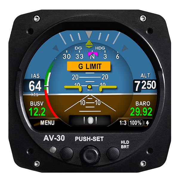
UAvionix Corporation’s aircraft AV-30-C panel display has received STC (Supplemental Type Certification) approval from the U.S. Federal Aviation Administration. The AV-30-C offers pilots an effective and affordable altitude indicator (AI) or directional gyro (DG) replacement with additional features.
AV-30-C is installable as either an AI or DG and adds a suite of in-flight information to the panel out of the box, including GPS navigational data, a probeless angle of attack indicator, baro-corrected altitude, indicated/vertical/true airspeed, non-slaved heading, bus voltage, G load and more with additional features to be announced.
AV-30-C is designed to fit into nearly any aircraft with a three and one-eighth inch round instrument slot without cutting or modifying the panel. By mounting from behind the panel, AV-30-C preserves the aircraft’s original classic look while bringing the latest that modern avionics has to offer to the panel.
The AV-30-C STC provides authorization to install in FAR Part 23 Class 1 and Class 2 aircraft (singles and twins weighing less than 6000 lbs) that are listed on the AV-30-C Approved Model List (AML), containing 635 Aircraft models including Cessna, Piper, Beechcraft, American Champion, Maule, Boeing, Swift, Mooney, Aviat and others. The full AML is available at uAvionix.com/AV-30.
AV-30-C works as a single primary instrument or by installing two units, one as an AI and another as a DG. The aircraft’s original failure-prone vacuum pump system can be removed to further benefit from a fully digital primary instrument cluster.
AV-30-C extends its functionality outside the cockpit as the companion to tailBeaconX, the latest 1090/ES ADS-B transponder with Aireon support for worldwide use and future mandated airspaces. Upon tailBeaconX TSO certification, AV-30-C can double as tailBeaconX’s control interface, allowing the pilot to set the mode and squawk easily, while maintaining AV-30’s existing feature set. tailBeaconX with AV-30-C removes the need to drill additional holes in the airframe to satisfy requirements in countries outside the U.S. and keeps installation costs to a minimum.
“uAvionix is creating avionics with fundamental engineering advantages,” said COO, Ryan Braun. “These are beautiful, no-compromise certified avionics designed to deliver an affordable total cost of ownership. The AV-30-C provides an innovative probeless angle-of-attack and non-slaved directional gyro, both designed to dramatically lower the cost of installation without compromising performance. Where other avionics seem designed to be replaced, the AV-30-C will get better with age. We’re actively developing ADS-B In, electronic flight bag, transponder, and autopilot integrations to ensure AV-30-C becomes an indispensable instrument for every panel.”
AV-30-C will support third-party autopilot systems via the APA-MINI adapter, interfacing AV-30’s heading bug with legacy autopilots. The APA-MINI autopilot adapter is expected to be released in early 2021, with more advanced autopilot integrations to follow.