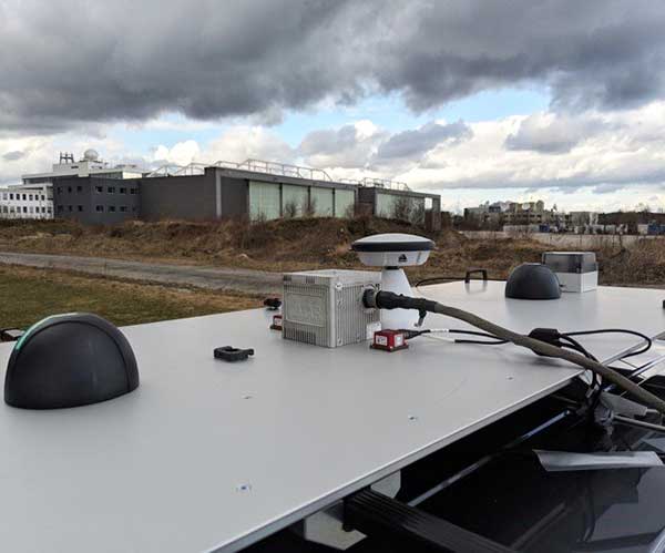
u-blox’ NEO-M8L module with 3D ADR technology and integrated sensors provides accurate vehicle position regardless of satellite visibility. (Image: u-blox)
U-blox has collaborated with Molex on the Modular Automotive Connectivity (MAX) Platform for intelligent vehicles.
The NEO-M8L and TOBY-L4 modules, which are built into the MAX connectivity platform, support the reception and transmission of data over the mobile network to the backend, enabling mobile internet access, in addition to supporting positioning. The solution can determine the position not only via GPS but also via Galileo, Beidou and GLONASS.
Molex is a Tier 1 system integrator and supplier of high-speed networking, datacom, rugged industrial and automotive solutions that enable innovative architecture design and development for the intelligent vehicles.
Molex will demonstrate MAX in booth 151 at ELIV Oct. 16-17 in Bonn, Germany.
The automotive-grade GNSS module NEO-M8L supports positioning, so that the ECU knows exactly where the vehicle is at all times. The solution can determine the position not only via GPS but also via Galileo, Beidou and Glonass. As a result, MAX can be deployed globally and offers a flexible and scalable solution for worldwide mobility providers, OEMs and system suppliers.
TOBY-L4 supports the reception and transmission of data over the mobile network to the backend, enabling mobile internet access.
MAX offers high-quality vehicle networking for both traditional and new mobility providers. MAX is suitable for small series, such as vans or targeted innovative EV projects. As a central node in the vehicle, MAX enables both internal and external networking. The solution is flexible, scalable and is an open software concept, fulfilling important requirements of the dynamic mobility market, Molex said in press release.
“MAX further supports our commitment to providing next-gen connectivity in the car for the entire market, not just a luxury for premium automakers. Molex innovations and expertise are driving solutions that are changing the automotive landscape to allow our customers accessibility,” said Dietmar Schnepp, product director for vehicle communication devices, Molex.
“We are delighted to work with a world leader in the automotive market such as Molex and proud to see two u-blox modules at the core of the new MAX connectivity platform,” said Andreas Thiel, head of Product Centers and co-founder of u-blox. “This collaboration demonstrates u-blox’s dedication to providing automotive customers with best-in-class positioning and wireless communications solutions.”
MAX can be tailored to the customer’s requirements through individual configuration. The platform combines quality of state-of-the-art communication technologies with the necessary degree of standardization for cost control.
In addition, the individual modularization enables a short time-to-market compared to tailor-made solutions. This path is the ideal alternative for telematics service providers who can use MAX as the basis for a backend connection, as well as for the development of various applications.
The new Mobile Mark nine-cable LTMG944 multiband antenna is designed for 5G-ready routers and gateways covering dual-carrier LTE MIMO, Wi-Fi MIMO and GNSS.
The LTM508 antenna. (Photo: Mobile Mark)
The 9-in-1 dual-carrier antenna expands Mobile Mark’s LTM series, used for public transit communications, public safety and vehicle fleet management. It contains nine separate antenna elements housed within a single antenna radome. The antenna has:
four cellular/LTE elements
four Wi-Fi elements
one GNSS element covering GPS, GLONASS and Galileo.
The LTM900 series can also be configured with fewer elements — for example, the LTMG942 contains four LTE, two Wi-Fi and one GNSS element.
The LTMG944 model can be paired with multi-connection 5G-ready routers and gateways already on the market. The cellular/LTE elements are designed to accommodate dual-carrier MIMO coverage (i.e. 2xMIMO on two different cellular carriers) or 4xMIMO for 5G.
Complete cellular coverage is offered from 694-960 and 1710-3700 MHz, with GNSS coverage on GPS and Galileo (1575 MHz) and GLONASS (1612 MHz), and dual-band Wi-Fi coverage on 2.4 and 5 GHz.
“Our new dual-carrier antenna solution series is compatible with the latest fleet management modems and routers offering dual-carrier coverage,” said Michael Berry, Mobile Mark president and CEO. “A single antenna provides MIMO coverage for each carrier.”
The antenna also provides broadband coverage. “We are happy to report that Mobile Mark’s new 9-cable 5G-ready antennas are in production today with efficient, 5 dBi gain on the FCC allocated 5G mid-bands of 3550-3700 MHz as well as being backwards compatible for other cellular frequencies,” Berry said.
The antenna is housed in the attractive, recognizable LTM radome in a choice of black or white. It is sold as a kit with 1-foot pigtails (LMR-100 except RG174 on GPS) and 14-foot jumper cables. The antenna elements fit in a compact radome that measures 5.5-inches in diameter by 2.38 inches high (140 mm x 60 mm). The LTMG944 series antennas are available as surface mounted antennas, but not as mag-mounts.
For high-vibration applications such as mining or large earth-moving equipment, Mobile Mark has developed a proprietary construction technique with superior shock and vibration test results. This option is available for the LTM944 series antennas.
The dual-carrier antenna is made in the USA, in Mobile Mark’s Itasca, Illinois, factory.”
VectorNav Technologies’ tactical series line of inertial measurement units (IMUs) and GNSS-aided inertial navigation systems (GNSS/INS) have completed independent testing for MIL-STD-810G, DO-160G, MIL-STD-1275E and MIL-STD-461.
Completion of the MIL-STD and DO-160 qualification tests proves the robustness of the tactical series to a range of temperature, shock, vibration and other environments, as well as conformance to numerous electrical interface and EMI standards.
The testing demonstrates an advantage of the tactical series for defense and aerospace applications. Other advantages are the modules’ SWAP-C (size, weight, power and cost) and performance characteristics.
“There is high demand for dependable, tactical-grade navigation solutions that perform in challenging environmental and operating conditions,” stated VectorNav Director of Sales and Marketing Jakub Maslikowski.
VectorNav’s tactical series includes the VN-110 IMU/AHRS, the VN-210 GNSS/INS and the VN-310 GNSS-compass aided GNSS/INS.
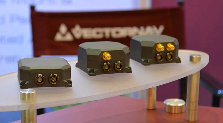
VectorNav’s new Tactical Series includes the VN-110 IMU/AHRS, the VN-210 GPS/INS and the VN-310 dual-antenna GPS/INS. (Photo: GPS World)
The products include an onboard tactical-grade IMU (<1˚/hr in-run gyro bias stability), along with VectorNav’s proprietary filtering, INS and GNSS-compass algorithms.
The products offer 1 to 2 mrad attitude performance in compact, rugged enclosures and include a 10-pin auxiliary port for integration with external real-time kinematic and SAASM-based GNSS receivers, as well as higher-performance IMUs.
Testing for the MIL-STD and DO-160 standards was performed by independent, certified testing companies in Plano, Texas, and Huntsville, Alabama.
As technological advances make GPS/GNSS devices more affordable, our lives are becoming increasingly dependent on precise positioning and timing. Industries such as survey, construction and logistics rely on precise positioning for automation, efficiency and safety.
GNSS time provides the pulsating heartbeat for the backbone of our industry by synchronizing telecom networks, banks and the power grid. A single day of GNSS outage is estimated to cost $1 billion U.S. dollars alone.
GNSS is a reliable system, and to keep it as such, professional GNSS receivers need to be wary of all possible vulnerabilities which could be exploited. Using GNSS receivers that are robust against jamming and spoofing is key for secure PNT (positioning, navigation and timing).
What is GPS/GNSS spoofing?
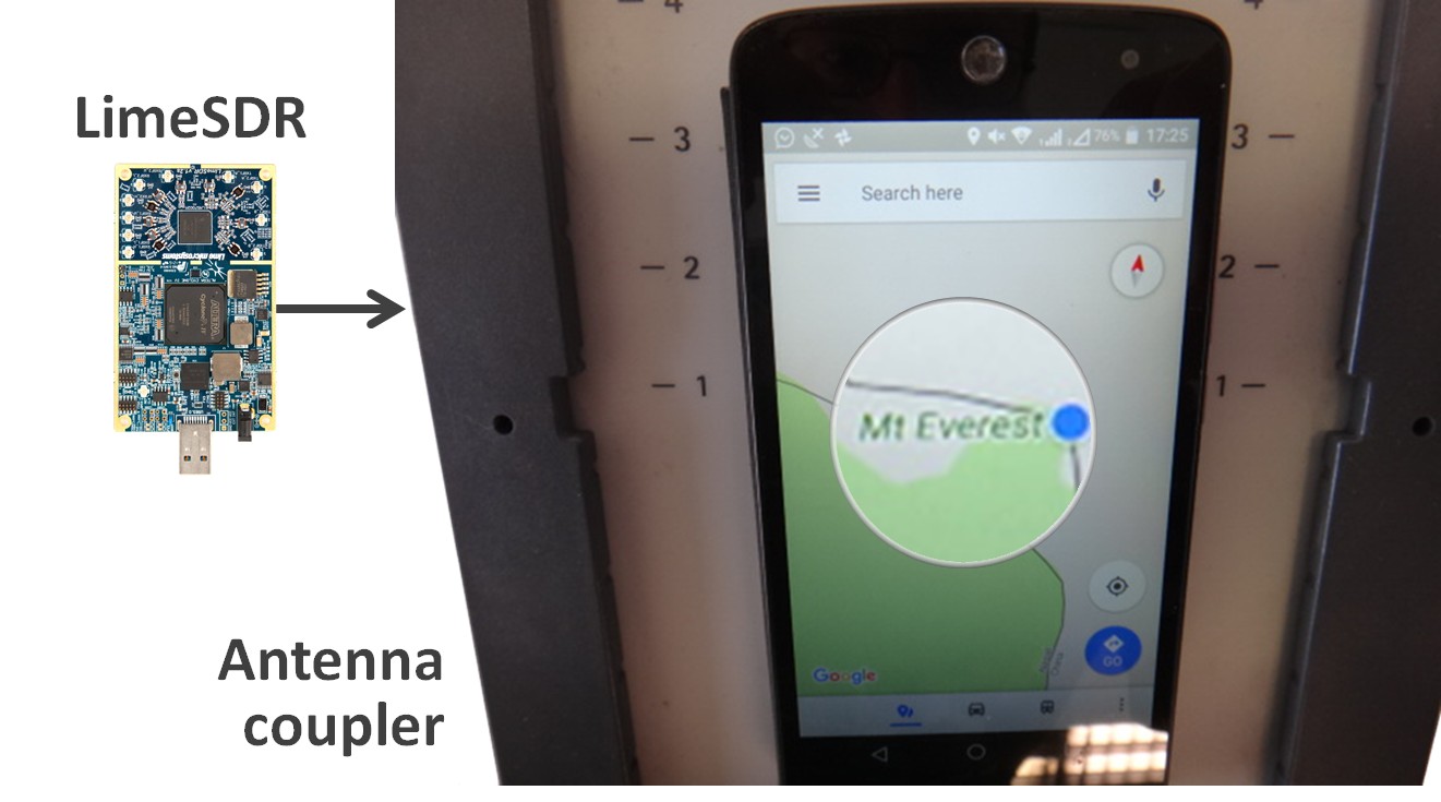
Radio interference can overpower weak GNSS signals, causing satellite signal loss and potentially loss of positioning. Spoofing, is an intelligent form of interference which makes the receiver believe it is at a false location. During a spoofing attack a radio transmitter located nearby sends fake GPS signals into the target receiver. For example, a cheap software-defined radio (SDR) can make a smartphone believe it’s on Mount Everest!
Figure 1. A cheap SDR can overpower GNSS signals and spoofs a single-frequency smartphone GPS into believing it is on Mount Everest. (Image: Septentrio)
Why GPS spoofing?
Imagine a combat situation. Clearly, the side which uses GPS/GNSS technology would have an advantage over the side which does not. But what if one side could manipulate GPS receivers of their adversary? This could mean taking over control of autonomous vehicles and robotic devices which rely on GPS positioning.
For example, in October 2018, Russia accused the U.S. of spoofing a drone and redirecting it to attack a Russian air base in Syria.
Figure 2. GNSS spoofing could be used to manipulate movement of aerial drones. (Image: Septentrio)
In the last three years, more than 600 incidents of spoofing have been recorded in the seas near the Russian border. These ships appeared to be “transported” to nearby airports.
This type of spoofing might have been introduced as a defense mechanism to ground spy drones. Most semi-professional drones on the market have a built-in geo-fencing mechanism that lands them automatically if they come close to airports or other restricted areas.
Some of the most enthusiastic spoofers are Pokémon GO fans who use cheap SDRs to spoof their GPS position and catch elusive Pokémon without having to leave their room.
Types of spoofing
Spoofers overpower relatively weak GNSS signals with radio signals carrying false positioning information. There are two ways of spoofing:
Rebroadcasting GNSS signals recorded at another place or time (so-called meaconing)
Generating and transmitting modified satellite signals
Spoof-proof: How can you protect your receiver against spoofing?
To combat spoofing, GNSS receivers need to detect spoofed signals out of a mix of authentic and spoofed signals. Once a satellite signal is flagged as spoofed, it can be excluded from positioning calculation.
GNSS receivers can offer various levels of spoofing protection. Let’s compare it to a house intrusion-detection system. You can have a simple entry alarm system or a more complex movement detection system. For added security you might install video image recognition, breaking-glass sound detection or a combination of the above.
Like a house with an open door, an unprotected GNSS receiver is vulnerable to even the simplest forms of spoofing. Secured receivers, on the other hand, can detect spoofing by looking for signal anomalies, or by using signals designed to prevent spoofing such as Galileo OS-NMA and E6 or the GPS military code.
Advanced interference mitigation technologies, such as the Septentrio AIM+, use signal-processing algorithms to flag spoofing by detecting various anomalies in the signal. For example, a spoofed signal is usually more powerful than an authentic GNSS signal.
AIM+ won’t even be fooled by an advanced GNSS signal generator: Spirent GSS9000. With realistic power levels and with actual navigation data within the signal, AIM+ can identify it as a “non-authentic” signal.
Other advanced anti-spoofing techniques such as using a dual-polarized antenna are being researched.
Satellite navigation data authentication
Various countries invest in spoofing resilience by building security directly into their GNSS satellites. With OS-NMA (Open Service Navigation Message Authentication), Galileo is the first satellite system to introduce an anti-spoofing service directly on a civil GNSS signal.
OS-NMA is a free service on the Galileo E1 frequency. It enables authentication of the navigation data on Galileo and even GPS satellites. Such navigation data carries information about satellite location and if altered will result in wrong receiver positioning computation. While currently in development, OS-NMA is planned to become publicly available in the near future. Also GPS is experimenting with satellite based anti-spoofing for civil users with their recent Chimera authentication system.
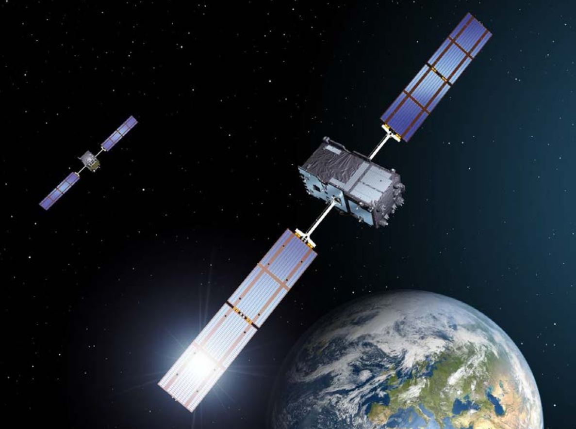
Figure 3. European Galileo satellites provide an open authentication service on the E1 signal and a commercial authentication service on the E6 signal. (Image: European Space Agency)
Recently, within the scope of the FANTASTIC project led by GSA, OS-NMA anti-spoofing protection was implemented on a Septentrio receiver.
The strongest shield: signal-level GNSS authentication
The Galileo system will be offering Commercial Authentication Service (CAS) on the E6 signal with the highest level of security for safety-critical applications such as autonomous vehicles. The signal level encryption will be based on similar techniques as the military GPS signals. Only the receivers who have the secret key are able to track such encrypted signals. The secret key is also needed to generate the signal making it impossible to fake. CAS authentication techniques are currently being prototyped at Septentrio in collaboration with the European Space Agency.
Spoof-resilient GNSS means reliable precise positioning and timing, and a peace of mind for everyone touched by this indispensable technology.
The importance of sensors, whether they be incorporated in cute dog robots or autonomous vehicles, is gaining more traction.
At September’s Custom Electronic Design and Installation Association (CEDIA) Expo, Sony Electronics President and COO Mike Fasulo told GPS World that its foundation sensors are going into autonomous vehicles, drones, agricultural solutions and other platforms.
“A lot of people also don’t know that more than half of the hardware in most smartphones is ours,” Fasulo said. “These sensors we are working on do things you and I can’t do. They can assess sunlight and darkness. They can put a safety cocoon around a vehicle.”
The Aibo robot dog uses artificial intelligence to mimic a real puppy’s behavior. (Photo: Kevin Dennehy)
At the conference, Sony displayed a nearly $3,000 Aibo dog robot, which has many of the same sensors that go into many of the company’s other products, including its venerable camera line. Aibo has facial recognition technology and uses artificial intelligence to mimic a real puppy’s behavior.
Sony sensors seem to be a cornerstone in several new announcements. Less than two months ago, Sony and Yamaha Motor Co. announced the joint development of the SC-1 Sociable Cart, a small autonomous vehicle that will be deployed to golf courses, amusement parks and commercial facilities, the company said.
The SC-1, which is not for sale, features five seats, replaceable batteries, front and rear scope of view thanks to image sensors, an innovative vehicle design, and other improvements over an original prototype vehicle.
In addition to the image sensors, the vehicle has ultrasonic sensors and a two-dimensional laser detection and ranging (lidar) system, the company said. These sensors allow the vehicle to gather cloud travel data for safe-driving analysis.
Sony is working with Japan’s NTT Docomo to test the vehicle’s 5G mobile technologies for remote-controlled functions, the company said.
Geotab leverages sensor data
Sony and Yamaha Motor plan to roll out the SC-1 later this year in Japan. (Photo: Sony/Yamaha Motor)
Canada-based Geotab has made big announcements this year, although the huge one is from the U.S. government to equip more than 200,000 vehicles with its telematics systems.
While that contract itself is massive, the company believes the more than 2 billion data points gathered each day, from millions of Geotab-equipped vehicles on the road, is the real valuable commodity.
The data gathered with the company’s connected-car technology can help companies and governments assess how their fleets are operating, said Mike Branch, Geotab vice president of data and analytics.
Branch, who leads a team of 40 employees, said the company uses the data to help cities assess road impediments — not only road quality. This includes analyzing ABS activation to look at black ice or other hazards. “While weather companies can only estimate conditions, we have sensors in vehicles that can give hyperlocal reports and ground truth,” he said. “People consistently slamming on their brakes in one area is an example [of aggregative data].”
Back in the day, which is less than 10 years ago, all that many companies expected from their fleet management systems was to let them know where their drivers were, by using GNSS and mapping technology. Today, the sensors — and data provided by them — allow managers to assess dangerous driving areas, save on fuel costs by rerouting trucks and compare routes throughout the United States, not just in big cities, Branch said.
In the smart cities space, Branch said that Geotab is working with municipalities for fuel intersection insight mapping. “This means if 20 vehicles, or even just two, are stopped at an intersection, our sensors can detect the wait times,” he said. “The big thing for us is looking at this smart-city deployment to leverage organic data in a private manner.”
Because of the nature of data procurement, privacy is big topic for the company, Branch said. “We treat it with high importance. Our view is that the data is owned by the customer,” he said. “They have full access to it. We will go through it, aggregately, so we can improve our customer’s experience.”
Keeping OBD port secure
The future of open on-board diagnostic (OBD) vehicles — and procuring secured and open data from them — is a concern for Geotab, Branch said.
“We have a full port safety committee with the goal of security and access to the port,” he said. “We believe in open access to this port. This gets to be a concern with mixed-fleet Fords, Mercedes, BMW and others as the data can slow down the port at any time.”
Branch said the company does not want to remove the entrepreneur, who is interested in working with the port in a safe manner. “We work with the OEMs on the future of telematics not just by pulling the data from our device, but pulling it from their feed,” he said.
Branch said that technology may make the port dongle obsolete in five to 10 years, but until then, the company has created an ecosystem to enable the use of the data. “There is going to be an aftermarket as cars are lasting an average of 11 years,” he said.
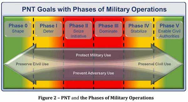
Calling PNT “foundational,” the strategy observes that the U.S. military has over the years structured its weapons systems and business processes around GPS PNT. This has created a tremendous dependence and associated vulnerability.
Added to this threat is the realization that “At the same time, it is increasingly clear… GPS will be targeted and will not always be available in contested military operating areas, or perhaps globally.”
Multiple diverse sources of PNT
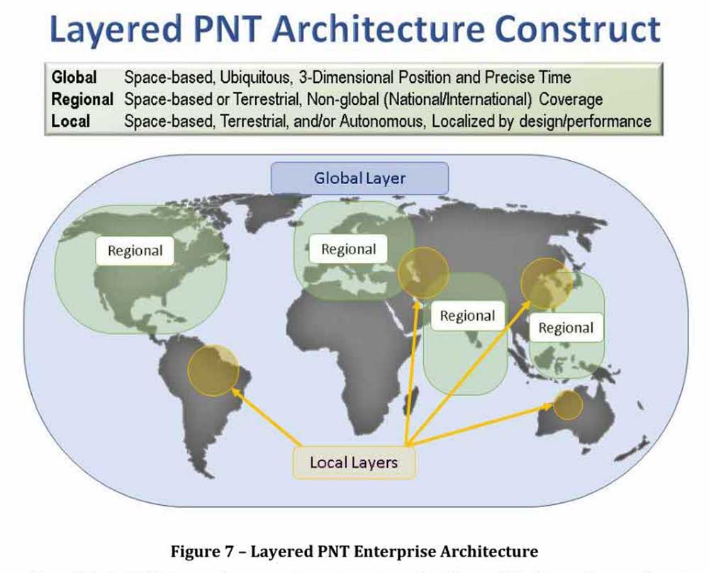
One of the primary ways DoD will deal with is this is to access multiple diverse sources of PNT. These will be in a multi-layered architecture of global, regional and local services.
The strategy envisions GPS, paired with military-grade receivers, as the primary global layer source. It recognizes that allied GNSS will be available, but observes that DoD has not done any accuracy and integrity assessments to determine their usefulness. And, since “…all are vulnerable to the same interference and jamming effects” as GPS, “…other sources of PNT information with different characteristics are necessary.”
The regional layer is defined by systems that service large areas such as a few countries or even continents. Recognizing that regional sources can be in space, the strategy discusses two low-frequency ground-based systems with characteristics much different from satellites — enhanced Loran (eLoran) and spatial, temporal and orientation information in contested environments (STOIC).
“Their high power and low frequency enable regional/nationwide coverage, spectrally separate from GPS services, accessible in buildings and under water, and transmitted from dispersed terrestrial locations. Each can be considered as a possible complement to GPS, depending upon operational circumstances and requirements.”
Short-range radio frequency systems, clock, inertial, sensory and hybrid PNT services integrated with wireless networks are all cited as possible contributors to the local layer of DoD’s PNT architecture.
Modular, open-systems approach
Receivers that employ a modular, open-systems approach that can ingest and integrate the various sources of PNT information are needed to take advantage of this multi-source, multi-layer strategy. And integration of the various sources must be seamless and invisible to the user, unless they decide otherwise.
“The employment of multiple PNT sources should not require user awareness or intervention to switch among alternatives during mission execution unless the user elects that option.”
A critical need for implementing this approach, according to the strategy, is the establishment of PNT input/output standards. The document notes that candidate standards have been developed, and it is vital to finalize and approve the standards and bring them into operational service as soon as possible.
Other provisions
The strategy includes a number of other provisions regarding internal DoD processes, the complicated governance process for PNT within the department, and some complex graphics that may be of interest to the larger PNT community.
It also sends several messages about the department’s desires, intent and concerns in the world of PNT that are worth noting.
NAVWAR. The department’s main defensive capability during navigation warfare will be the use of its layered architecture of PNT information and modular, open-systems integration. For offensive operations, it cautions warfighters to not shoot themselves in the foot. PNT is so vital to a wide variety of allied systems, it warns, that denying it to hostiles could do as much damage to friendly forces.
PNT dominience/superiority. At at time when there are more of China’s brand new BeiDou satellites in the skies of many cities, and China is negotiating with Russia for closer BeiDou/GLONASS integration, the strategy calls for the U.S. DoD to achieve PNT dominance. To date, U.S. PNT leadership has been a big contributor to the nation’s political and military leadership in the world. The strategy seeks to continue this.
Accelerate M-code receivers. The need to get more M-code GPS receivers into the hands of warfighters is mentioned several times. GPS III satellites have been transmitting M-coded signals that are much more resilient to jamming and spoofing than civil signals since late 2018. These are useless, though, without properly equipped receivers in the field.
Future support to Civil PNT. The strategy also seems to show the department is distancing itself from support of future civil PNT endeavors. While GPS has been an incredible economic engine and boon to civil users, this has not always been in DoD’s best interests.
“It must also be recognized that in this context growing civil dependence on GPS services for critical infrastructure and public use will continue to constrain the ability of the DoD to maintain a military PNT advantage from GPS.”
It goes on to warn that future DoD PNT systems and efforts will not follow the same path to civil-military use as was taken by GPS.
“DOD must take steps to ensure the civil agencies are aware of and are sensitive to the dual-use implications inherent in GPS and other PNT Enterprise applications. From this point forward, many of the specific PNT capabilities and combinations of PNT capabilities employed by the DoD for military purposes will increasingly be classified.”
The way ahead for the 99%
It is clear that the Department of Defense, through the very capable leadership of its CIO, Dana Deasy, has a clear idea of where it is with PNT, its critical challenges, and how to overcome them.
This does not appear to be the case for those in the federal government charged with safeguarding the interests of civil users. With responsibilities fragmented across a host of departments and agencies, efforts on behalf of the public at large are barely visible compared to those the Defense Department is taking to protect itself.
According to officials, this may change. They report that leadership of civil PNT within the executive branch is under review with an eye to making it more efficient and effective.
Perhaps it will result in a PNT strategy for the 99% of GPS users who are not connected with the Defense establishment, making them safer and more secure as well.
“Strategy for the Department of Defense Positioning, Navigation, and Timing (PNT) Enterprise” is available online.
World View, the stratospheric exploration company, has reached an important milestone representing a key step toward persistent and navigational stratospheric flight.
After achieving the goal of more than 30 days aloft with full navigational control, the Stratollite completed its 32-day mission over the weekend, showcasing its enhanced long-duration flight capability.
Before this mission, the longest Stratollite flight was 16 days, achieved in June 2019. This mission moves World View closer to scaled commercial operations, making the unique data and information sets it can provide available to commercial and government Earth-observation and remote-sensing customers around the world.
Notable accomplishments from the mission:
Executed four continuous days of station-keeping (mission objective) with an average distance of 20 km from the first predetermined target location, followed by an intentional navigation to the second station-keeping target location 1,230 km away.
Achieved 2.5 days of continuous station keeping at the second station-keeping target with an average of 40 km from the second target location.
Averaged an altitude of 19.5 km during both station-keeping exercises.
Traveled more than 11,200 km during the mission, covering Arizona, Utah, Nevada, Colorado, New Mexico, Texas, Oklahoma, Nebraska, Iowa and Kansas.
Demonstrated complete navigational control during the mission from World View’s remote Mission Control in Tucson, Arizona.
The total mission duration was 32 days, 5 hours and 14 minutes
Executed more than 1,000 trajectory-control maneuvers over the entire mission.
“This is another encouraging milestone for the team and our customers that confirms we are on the right track,” said Ryan Hartman, World View president and CEO. “It sets the stage for a challenging set of missions ahead of us as we continue to push the envelope and demonstrate the ability of the Stratollite to meet customer requirements.”
World View’s flight operations team landed the Stratollite at a predetermined landing zone in Iowa on Saturday, Sept. 28, to conclude the mission. The system landed on command, was recovered, and will be refurbished for reuse on future missions.
World View will continue to increase the cadence of its Stratollite flight operations. The company plans to launch multiple missions focused on demonstrating optical imaging and synthetic aperture radar sensing systems with further enhancement of station-keeping and navigational performance.
About the Stratollite. World View’s Stratollite is a long-endurance stratospheric flight vehicle capable of station-keeping over areas of interest for remote sensing and communications.
The craft can travel 95,000 feet above the Earth. World View is already routinely flying payloads to the edge of space for a wide variety of government, commercial, and education customers.
World View’s proprietary altitude-control technology allows it to harness stratospheric winds to steer the Stratollite to and from desired locations and loiter above them for long durations.
Stratollites can carry a wide variety of commercial payloads (sensors, telescopes, communications arrays, etc.), launch rapidly on demand, and safely return payloads back to Earth after mission completion.
Among its wide variety of uses, the Stratollite will help researchers greatly advance knowledge of planet Earth, improve our ability to identify and track severe weather, and assist first responders during natural disasters.
Haiti Outreach is on a mission to bring clean drinking water to 100% of Haitian communes. The non-profit organization is using EOS Positioning Systems’ Arrow Gold GNSS receivers to transform how water access is addressed.
In the Western Hemisphere’s poorest nation, poverty and corruption have stifled development. But Haiti Outreach is using geospatial software and donations to ensure every household has access to clean drinking water. Their technology includes mWater, EPANET, and Arrow Gold with Atlas.
In this video, you’ll hear from Haiti Outreach Director Neil Van Dine and Eos Positioning Systems CTO Jean-Yves Lauture on the importance of combining spatial strategy with a human element.
In Haiti 95% of unprotected springs are contaminated with E. coli, with 48% of water infrastructure across 50 communes delivering water contaminated with E.coli (Haiti Outreach 2018 study). For 22 years, a nonprofit called Haiti Outreach has tried to increase access to clean water by drilling wells for Haitian communities (called communes).
Haiti Outreach tried drilling new wells, but that didn’t solve the problem. The answer is education. “It’s all about creating a transformation in the way we think,” Van Dine said. “Water is free, but somebody has to maintain the well, replace parts, and so on in the long term. All those things cost money.”
Achieving a 50-cents per household fee for maintenance, Haiti Outreach still needed to know if everyone in Haiti had access to clean drinking water. The organization needed to know the location of every household in relation to water sources. They also needed to know if these water sources were clean, contaminated, functioning or broken.
Outreach decided to use the open-source hydraulic-modeling software EPANET, from the U.S. government, and hired mWater to build an integration. By running population-density overlays in mWater, it was possible to identify where there were enough households (25) to create a revenue stream to support a new well. With 100 households, the revenue could support a new in-home water-distribution network.
Photo: Haiti Outreach
They also used Android phones and Arrow Gold with Atlas. By pairing the Arrow Gold with Atlas, they were able to get decimeter accuracy. (Atlas is a satellite-based differential correction service.)
“The Android phones got about 10 meters of accuracy on their own,” Haiti Outreach fieldwork coordinator Micki Johns said. “But the Arrow Gold with Atlas got us within that decimeter range.”
Data collected in mWater went into EPANET to simulate water pressure and flow.
Haiti Outreach used the findings to develop a community action plan (CAP). The CAP prioritized cleaning contaminated sources and ranked contaminated sources by the highest number of people who would benefit from a decontamination.
Richard Wiegmann as President and CEO. (Photo: VertiGIS)
The board of directors for VertiGIS, a geographic information systems (GIS) software and solutions provider, appointed Richard Wiegmann as president and CEO.
Wiegmann began his new role Aug. 1.
VertiGIS comprises Esri Platinum Partners AED-SICAD, Geocom Informatik and Latitude Geographics (Geocortex), and aED-SYNERGIS, Dynamic Design and SynerGIS GIS & FM.
Wiegmann, 49, lives with his family near Frankfurt. He brings extensive executive experience in software and services to the operational management of VertiGIS and was one of the company’s original board members. Previously, he was CEO and chief commercial officer of Sabre Hospitality Solutions, which in 2016 acquired Trust – International Hotel Reservation Services.
“I’m excited to join the team at VertiGIS, and see so much potential for us in the GIS market and beyond,” Wiegmann said. “By bringing together major GIS companies, we can leverage the expertise of our employees and the strong cooperation of partners like Esri to provide our customers the best-in-market solutions for their businesses, and ensure they offer long-term stability and planning security.”
VertiGIS’ product portfolio is used by more than 12,000 users in private-sector companies and government agencies. Current product brands include UT for ArcGIS, the 3A product line, Geocortex, GEONIS, ConnectMaster, GeoOffice, WebOffice and ProOffice.
“I look forward to further developing our existing products and services with a great team, and bringing new ideas together in this highly interesting growth market,” Wiegmann added.
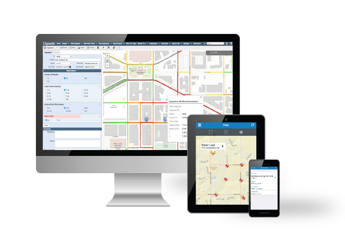
Trimble has signed a definitive agreement to acquire privately held Azteca Systems LLC (Cityworks), a provider of enterprise asset management (EAM) software for utilities and local government.
Cityworks’ solutions address the global challenges associated with maintaining and replacing aging utility, transportation and public assets and infrastructure.
The transaction is expected to close in the fourth quarter of 2019, subject to customary closing conditions and expiration of the waiting period u
nder the Hart-Scott-Rodino Antitrust Improvements Act. Financial terms were not disclosed.
Cityworks, based in Sandy, Utah, was launched in 1996 and provides a powerful and flexible office, cloud and mobile EAM software solution that is used by more than 700 utilities and local governments. EAM is a key technology and system of record relied on by organizations to address a wide range of applications in infrastructure development, maintenance and permitting.
Cityworks is a leader in the mid-sized utility and local government market segments in North America and its solutions address organizations of all sizes with deployments serving some of the largest cities in the U.S.
The Cityworks acquisition will expand Trimble’s strategy by adding an EAM software platform to its existing utilities and local government capabilities, which include mobile, IoT and infrastructure lifecycle solutions. The combination will provide a comprehensive digital platform — with real-time asset intelligence, workflows and analytics — for transforming the way governments and utilities prioritize infrastructure maintenance and construction investments.
In addition, the acquisition will enable Cityworks to leverage Trimble’s global footprint in multiple industries.
Together, Trimble and Cityworks will provide an expanded solutions portfolio to their partner network of architecture, engineering and construction (AEC) firms and software system integrators.
Customers will benefit from integrated solutions that will enable them to realize improved infrastructure performance, increased productivity and better return-on-investment associated with infrastructure construction and operation.
“Cityworks is a pioneer in developing software to address the global challenges associated with managing aging, critical infrastructure,” said Steve Berglund, president and CEO of Trimble. “Trimble has a long history of transforming industries by combining technologies and providing full solutions that help customers measure, assess, design and construct infrastructure at scale. With Cityworks, we now expand our solutions portfolio enabling customers to manage and optimize the performance of their assets across the entire infrastructure lifecycle.”
“Trimble is an ideal match for Cityworks and the work we aspire to do in helping utilities and communities improve public infrastructure management. Joining Trimble is strategic, providing exciting growth opportunities and new opportunities for innovation,” said Brian L. Haslam, founder, president and CEO of Cityworks. “Cityworks as a Trimble company will accelerate our GIS-centric public asset management approach and allow us to increase the impact and value our solutions deliver to customers.”
The Cityworks business will be reported as part of Trimble’s Resources and Utilities Segment.
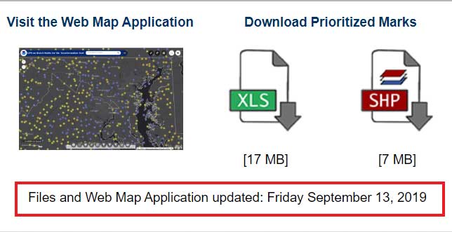
My last column highlighted the next phase of the National Geodetic Survey’s (NGS) GPS on Bench Marks program; that is, the development of the 2022 transformation model. It provided web links to material explaining the new GPS on Bench Marks program. NGS continues to update this site so I would encourage users to periodically check the site for updates. At the time of this column, the site was updated on Sept. 13. See the box titled “GPS on Bench Mark Web Page.”
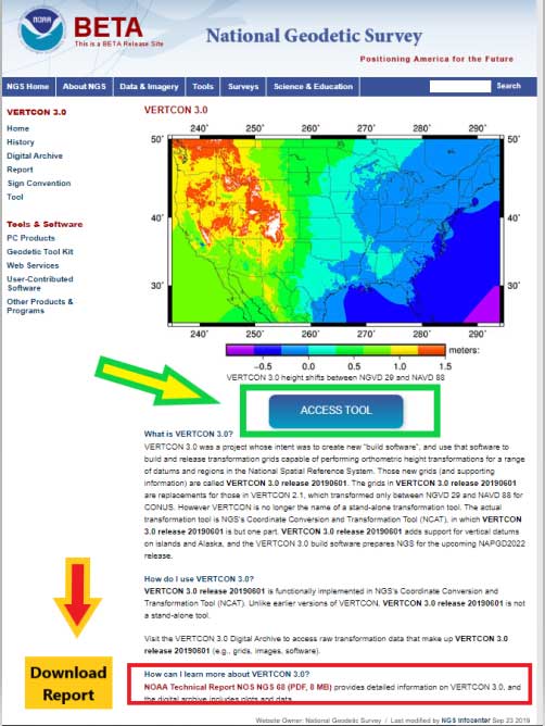
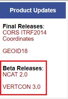
This column is going to focus on the newly released beta version of NCAT 2.0, which includes the new beta version of VERTCON 3.0. See the box titled “NGS Product Updates.”
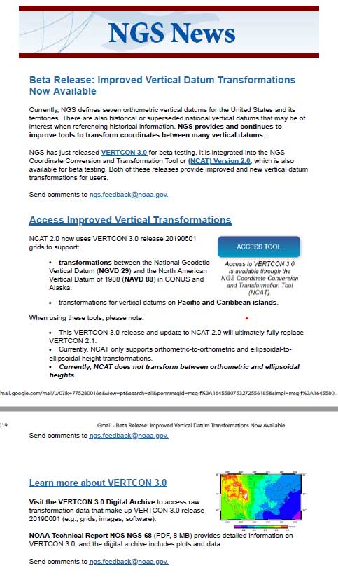
On Sept. 24, NGS sent an NGS News Update through its data delivery system. See the box titled “NGS News Announcement of VERTCON 3.0.”
NGS News Announcement of VERTCON 3.0
Image: National Geodetic Survey
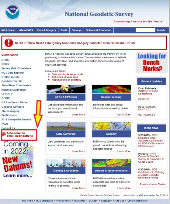
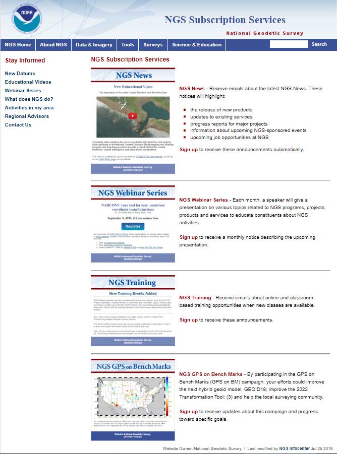
As a side note, anyone can sign up for NGS News announcements by clicking on the button titled “Subscribe for email notifications” on the left side of NGS Home Page. See the box titled “Subscribe for NGS Email Notifications “
First, NGS published a technical document that provides a brief history of previous versions of the VERTCON model and the technical details of the new beta VERTCON 3.0 model. The report is titled “NOAA Technical Report NOS NGS 68,The VERTCON 3.0 Project” and can be downloaded here.
NGS decided to update the existing VERTCON tool with two primary purposes in mind:
to support as many of the vertical datums of the NSRS as possible, and
to prepare users for the new North American-Pacific Geopotential Datum of 2022 (NAPGD2022).
NGS plans include incorporating the new VERTCON 3.0 model into its integrated products and services. See the box titled “Excerpt from NOAA Technical Report NOS NGS 68, The VERTCON 3.0 Project: Motivation for VERTCON 3.0.”
As a matter of fact, the beta version of VERTCON 3.0 is included in an updated beta version of the NGS Coordinate Conversion and Datum Transformation Tool (NCAT). This column will provide examples converting NGVD 29 heights to NAVD 88 heights using the new beta versions of NCAT and VERTCON.
Excerpt from NOAA Technical Report NOS NGS 68, The VERTCON 3.0 Project: Motivation for VERTCON 3.0
The greatest driver for VERTCON 3.0 was the pending release of NAPGD2022, expected in late 2022. As part of that release, NGS intends to release grids to transform between existing vertical datums and NAPGD2022. As the build software used to create all previous versions of VERTCON was no longer available, it was decided (like NADCON; see Smith and Bilich, 2017) to completely recreate the entire suite of VERTCON build software.
However, unlike horizontal datums, the history of vertical datums at NGS is, as mentioned earlier, quite limited. As a transformation can only exist if two datums are released in a region, this limits what expansion to VERTCON 2.1 might be possible. Nonetheless, most regions at least had “Local Tidal” heights published by NGS as well as some other official vertical datum of the NSRS, so a decision to support transformation in these regions was made.
Knowing that such a re-build would replace VERTCON 2.1, the new project and its build software were designated from the beginning as “VERTCON 3.0”.
Other expected advantages with this project were the chance to update documentation and the delivery of the transformations, through incorporation into newly integrated products and services like the NGS Coordinate Conversion and Datum Transformation Tool (NCAT, available at https://www.ngs.noaa.gov/NCAT/) and VDatum (available at https://vdatum.noaa.gov/).
Users can access the VERTCON 3.0 model by clicking on the VERTCON 3.0 link on NGS Home Page. It will direct the user to this website.
See box titled “VERTCON 3.0 Web Site.” The user can also download the Technical Report from this site.
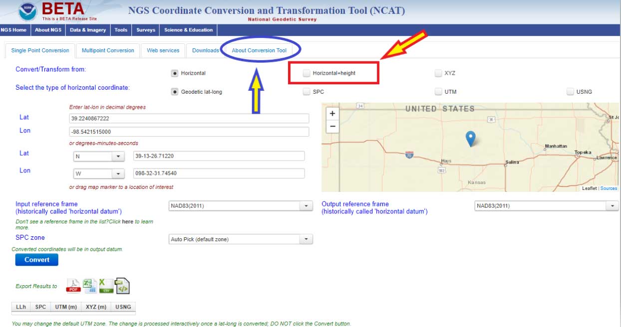
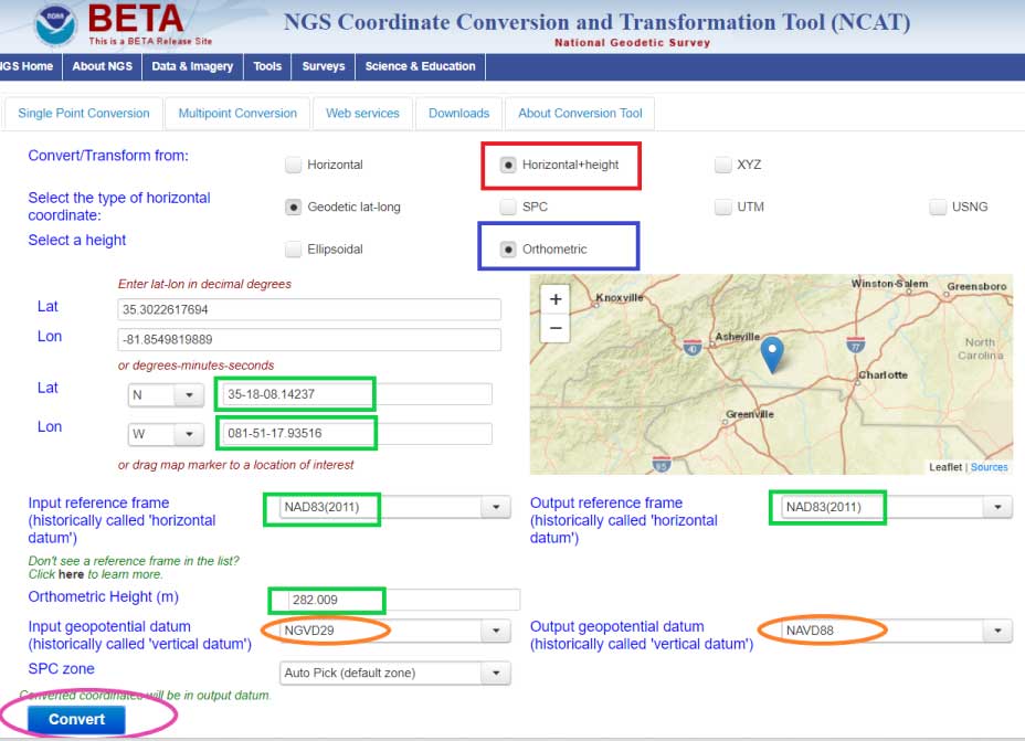
Clicking on the “Access Tool” button” connects the user to the Beta NCAT website. See box titled “Beta NCAT Website.” Two links have been highlighted in the box: “About Conversion Tool” and “Horizontal+height.”
The default values for the beta NCAT are “Horizontal” and “Geodetic lat-lon.” If the user wants to use the VERTCON 3.0 option, he or she must click on the button “Horizontal+height.”
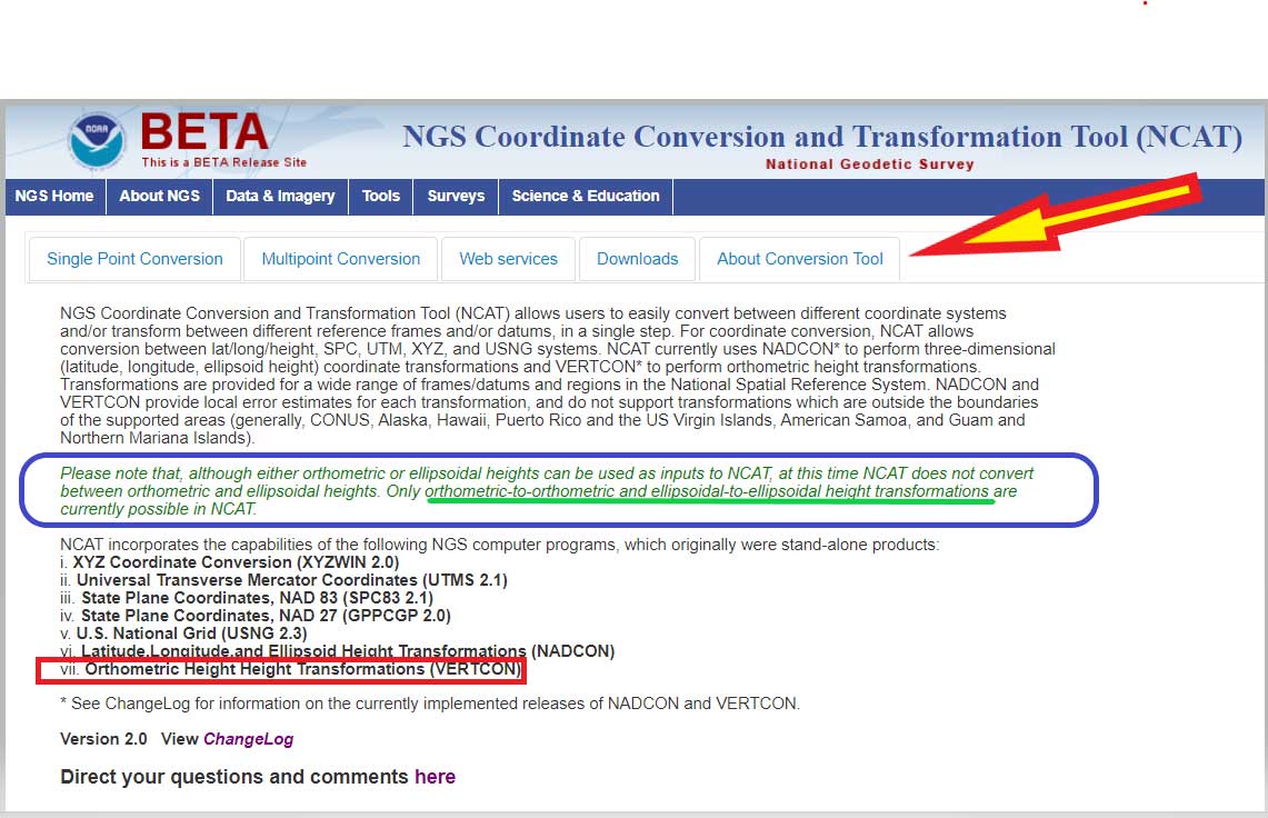
Clicking on the “About Conversion Tool” provides a brief description of the tool. I’ve highlighted a section in the description that should be pointed out to users. See the box titled “NCAT Brief Description” and the statement below.
“Please note that, although either orthometric or ellipsoidal heights can be used as inputs to NCAT, at this time NCAT does not convert between orthometric and ellipsoidal heights. Only orthometric-to-orthometric and ellipsoidal-to-ellipsoidal height transformations are currently possible in NCAT.”
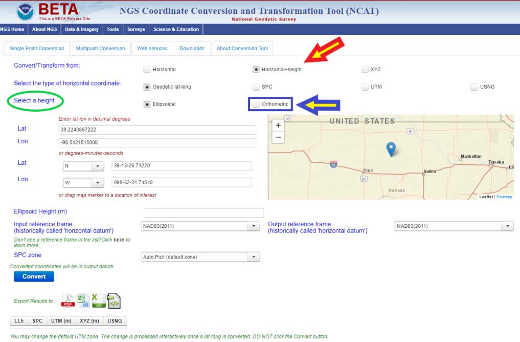
What this means is that you can convert, at this time, stations located in the Conterminous United States and Alaska from NGVD 29 to NAVD 88, and from NAVD 88 to NGVD 29. In order to convert from one orthometric height system to another, you have to click on another button. I’ve highlighted the button in the box titled “Single Point Conversion – Horizontal+height.” Clicking on the button “Horizontal+height” initiates another set of buttons under the section titled “select a height.” There are two options ellipsoid or orthometric. The ellipsoid button is the default option. If you want to convert a height from the NGVD 29 datum to the NAVD 88 datum the user needs to select the button titled “orthometric.”
Single Point Conversion – Horizontal+height
Image: National Geodetic Survey
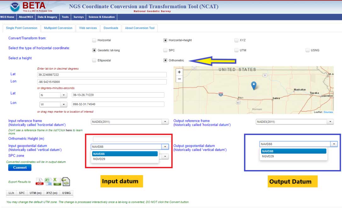
The box titled “Select a Height Option” is a screenshot of the site after the user clicks the “Orthometric height option. The user can now select the input and output vertical datums. The input and output datum options are highlighted in the box.
Select a Height Option
Image: National Geodetic Survey
Once you select the input and output vertical datums, you need to input the latitude and longitude of the station, select the reference frame, and input an orthometric height value to be converted. You must enter an orthometric height that you want to be converted. The box titled “Converting from NGVD 29 to NAVD 88 – Input Parameters” provides an example for station RU 36 (PID FA1337) located in Rutherford County, North Carolina.
Converting from NGVD 29 to NAVD 88 – Input Parameters
Image: National Geodetic Survey
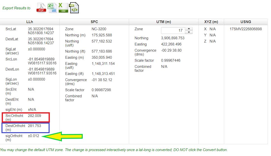
After you enter your input parameters, click on the button titled “Convert.” The box titled “Converting from NGVD 29 to NAVD 88 – Output Solution” provides the output from Beta NCAT tool. The input height and output heights are highlighted in the box. The solution also provides an estimate of the accuracy of the value (SigOrthoht).
Converting from NGVD 29 to NAVD 88 – Output Solution
Image: National Geodetic Survey
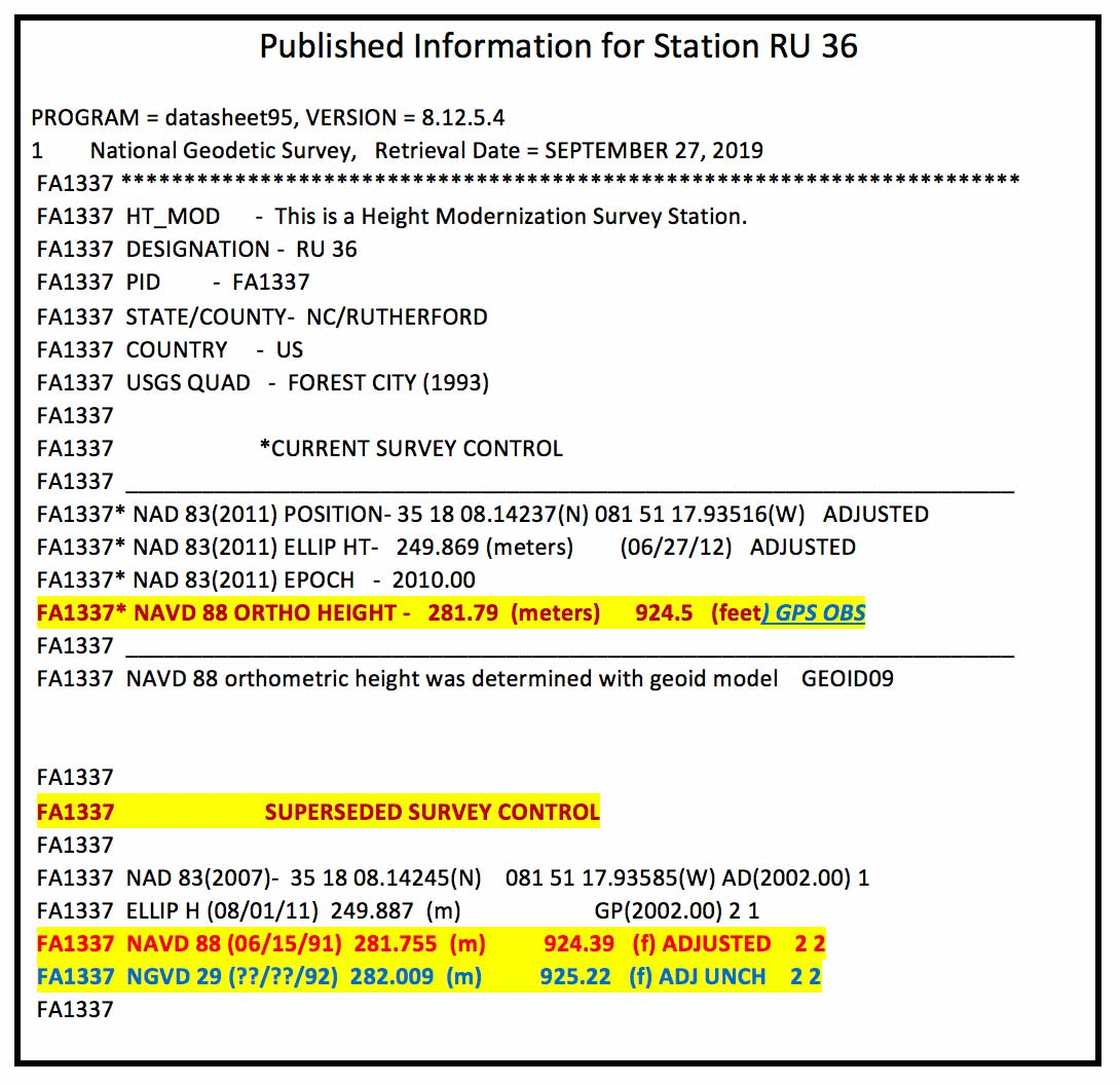
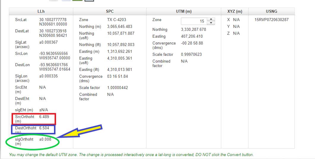
The published information for RU 36 (PID FA1337) is listed in the box titled “Published Information for Station RU 36.” The NGVD 29 height converted to a NAVD 88 orthometric height from the Beta NCAT tool agrees with the superceded NAVD 88 height to within a couple of millimeters (281.753 m minus 281.755 m = -0.002 m). Saying that, the station was superseded with a GNSS-derived orthometric height and the difference is a little larger, 281.79 m minus 281.753 m = 0.037 meters. I’m not saying that there’s anything wrong with the conversion model, I’m only highlighting that, in this case, it agrees with the NAVD 88 leveling-derived heights even though that station has been superceded by a GNSS-derived orthometric height. Users should be aware of this.
Published Information for Station RU 36
Data: National Geodetic Survey
Also, it should be noted that the current version of VERTCON is based on published NAVD 88 heights as of a certain date. If a station has been readjusted since VERTCON 3.0 was generated, then the difference between the modeled value and the published value may be different. The actual difference will depend on how much the newly published orthometric height differs from the previously published orthometric height. If a single station’s height changed due to being disturbed by a local phenomenon such as road construction equipment, then the VERTCON value should still be valid.
However, if the heights of several stations in a region changed due to a regional phenomenon such as crustal movement and/or a large adjustment distribution correction due to a regional vertical control network adjustment, then the VERTCON values may not provide the best estimate of the difference between the two datums.
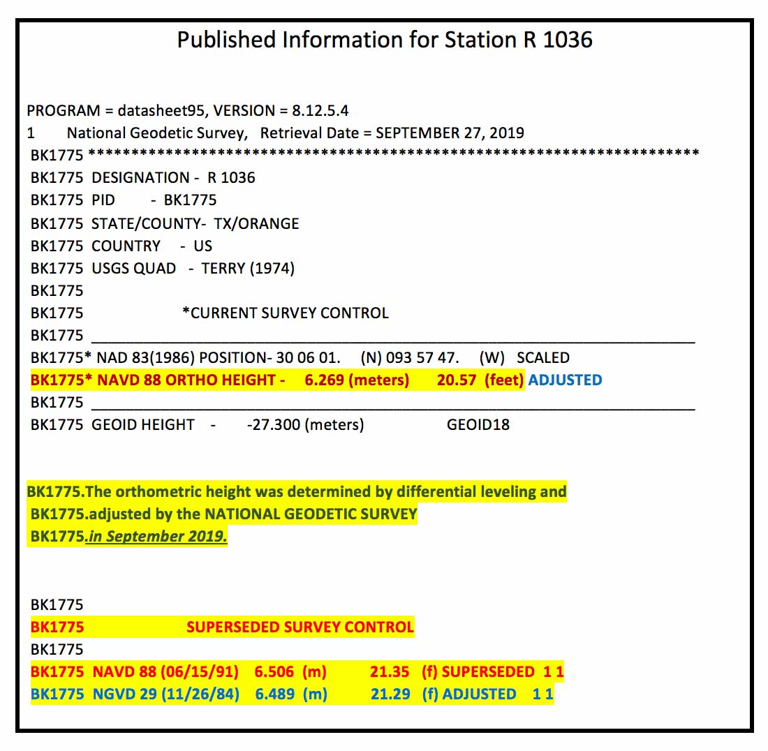
An example of this is provided in the boxes titled “Published Information for Station R 1036” and “Converting from NGVD 29 to NAVD 88 – Output Solution for Station R 1036.” Station R 1036’s NAVD 88 height was updated in September 2019 ,which was after the creation of the VERTCON model. This means that the latest published NAVD 88 height (6.269 m) would not have been used in the model. The newly adjusted NAVD 88 height and the superseded height differ by –23.7 cm (6.269 m – 6.506 m). In this case, this is not an isolated change of a single station’s published height. The adjusted heights of the stations in the region have all changed due to apparent crustal movement and/or a large distribution correction due to a vertical network adjustment.
Published Information for Station R 1036
Data: National Geodetic Survey
The box titled “Converting from NGVD 29 to NAVD 88 – Output Solution for Station R 1036” provides the converted NAVD 88 height using the NCAT tool. The converted NGVD 29 to NAVD 88 value differs by 23.5 cm (6.504 m minus 6.269 m). Which is expected because the newly published height and superseded height differ by 23.7 cm. It agrees to within 2 mm of the previously published NAVD 88 height (6.506 m minus 6.504 m = 0.002 m). Once again, this is not implying that there is something wrong with the VERTCON model. It’s only to note the limitations of the model. Users need to remember that it is a model and it does not produce geodetic quality coordinate values.
Converting from NGVD 29 to NAVD 88 – Output Solution for Station R 1036
Image: National Geodetic Survey
Users can also convert from other vertical datums published by NGS. These datums include:
Puerto Rico Vertical Datum of 2002 (PRVD 02)
American Samoa Vertical Datum of 2002 (ASVD 02)
Northern Mariana Vertical Datum of 2003 (NMVD 03)
Guam Vertical Datum of 2004 (GUVD 04)
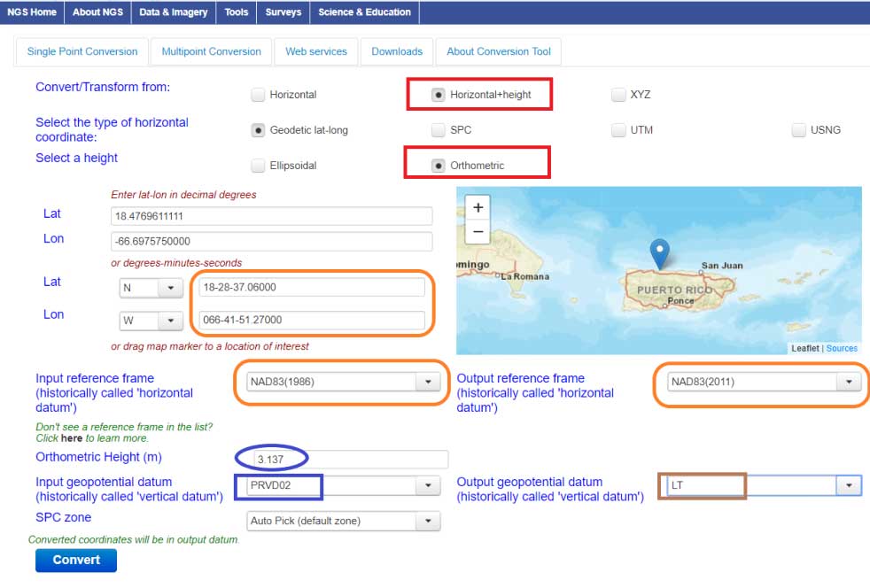
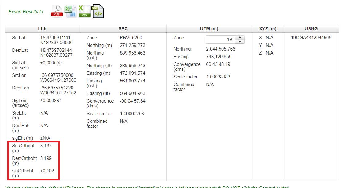
An example of converting a station with a PRVD 02 orthometric height to a Local Tide (LT) value is provided is the boxes titled “Converting from PRVD 02 to Local Tide (LT) – Input Parameters“ and “Converting from PRVD 02 to LT – Output Solution for Station 11 R RESET.”
Converting from PRVD 02 to Local Tide (LT) – Input Parameters
Image: National Geodetic Survey
Converting from PRVD 02 to LT – Output Solution for Station 11 R RESET
Image: National Geodetic Survey
Notice that the difference between the PRVD 02 and converted LT value differ by 0.062 m but the accuracy estimate is +/- 0.102 m.
In my opinion, the VERTCON model and the NCAT tool are extremely helpful tools to the surveying and mapping community. NGS is developing these models and tools to support the implementation of the North American-Pacific Geopotential Datum of 2022 (NAPGD2022). I would encourage all users to download the technical report and perform a couple of conversions in your area of interest.
NGS would like individuals to use the beta products and services and provide feedback. What do you like about the tool and its features? What would you like changed or added to the service? I hope everyone will try the beta version and contact NGS with their comments.
NGS is in a listening mode and wants to develop models and tools to assist users in their transition to the new reference frames in 2022. This is your opportunity to let NGS know what you need (desire) to implement the new reference frames.
A pair of testbed vehicles went out on the road in Germany to simulate the way we are all likely to be using 5G positioning services in the future. The field test focused on assessing the performance of highly precise hybrid satellite/terrestrial positioning for autonomous vehicles, drones, smart cities and the internet of things (IoT).
The two vehicles were driven for a week around Munich and the surrounding area in a variety of environments, from the open-sky terrain surrounding the German Aerospace Center DLR’s site in Oberpfaffenhofen to the deep urban canyons of the city’s dense Maxverstadt district.
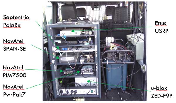
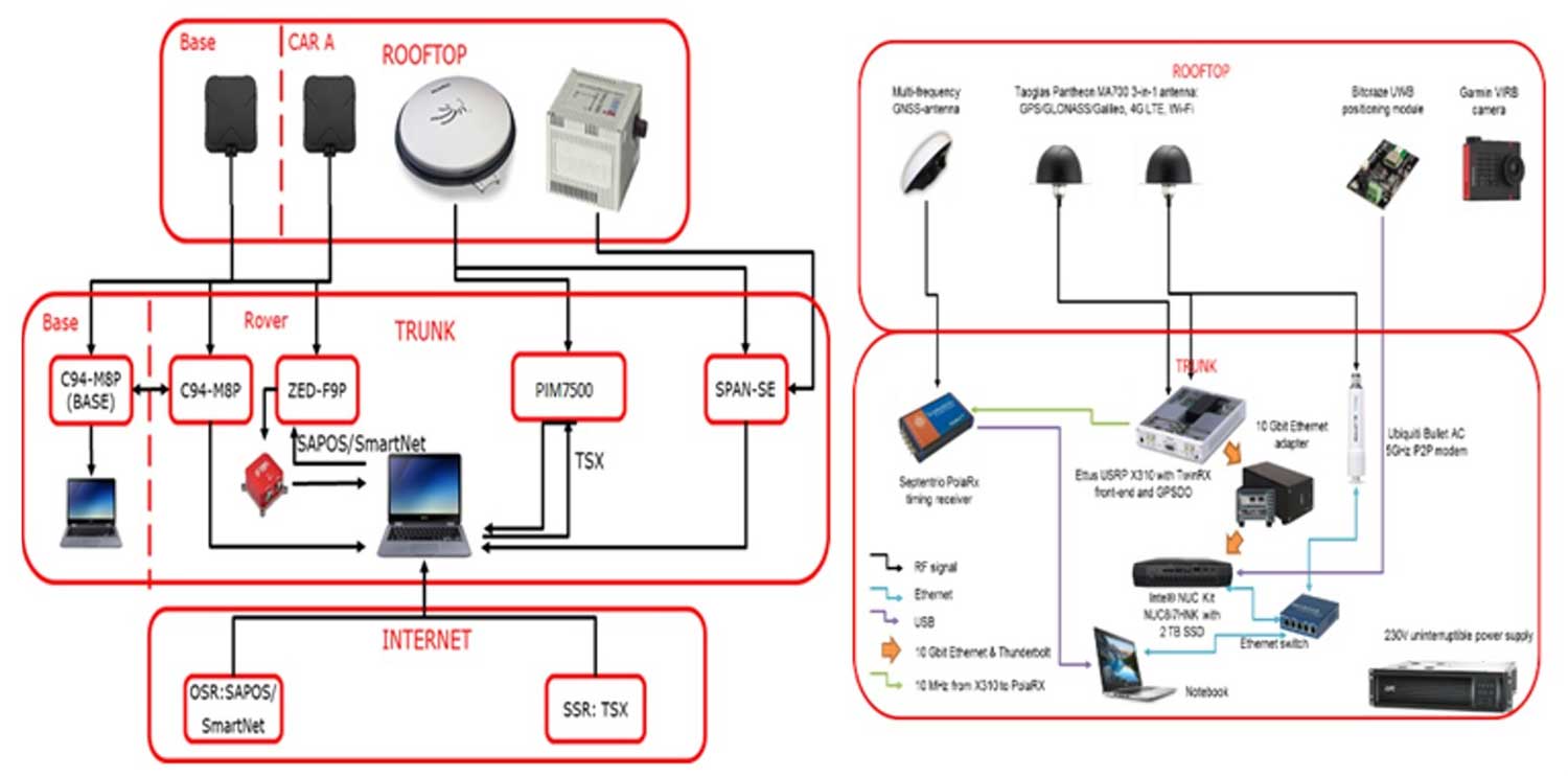
As they drove, they combined a broad range of on-board systems to measure their positions and share them with one another, performing ongoing vehicle-to-vehicle ranging to simulate future 5G operating standards.
The on-board systems included multi-constellation satellite navigation (combining Europe’s Galileo, the U.S. GPS, Russian GLONASS and Chinese BeiDou), incorporating localized high-accuracy correction, and 4G Long-Term Evolution (LTE) and ultra-wideband (UWB) terrestrial wireless broadband communication.
The coming of the next generation of mobile phone networks, 5G, promises much faster, more stable connectivity based on higher bandwidths and frequencies, but the ability to download a full movie in a matter of seconds is only the start. The increased capabilities will also open up a new range of services, many of them based around localization.
From smart traffic management to asset tracking to personalized drone-based delivery, our receivers’ ability to know where they are and share those positions with the wider network will be vital.
Close-up view of Car A with GNSS and LTE antennas. (Photo: ESA)
“The first step required is understanding what the upcoming disruptive applications are, and to identify the potential requirements associated with them,” said Riccardo de Gaudenzi, who leads ESA’s Electrical Department in its Directorate of Technology, Engineering and Quality.
“For these use cases, positioning and timing are key elements. Therefore positioning, navigation and timing (PNT) aspects, provided via GNSS like Galileo, the terrestrial communication infrastructure and hybridization of technologies, are extremely important.”
The testbed vehicles combined a broad range of on-board systems, including multi-constellation GNSS, incorporating localized high-accuracy correction. (Image: ESA)
Today we rely largely on satellite navigation to determine where we are. But our smartphones quietly blend satnav with other data sources to sharpen the accuracy of their results. That is why, for example, when you turn off your phone’s Wi-Fi receiver, your smartphone will warn you its mapping will become less accurate – it is also using Wi-Fi maps as a reference source.
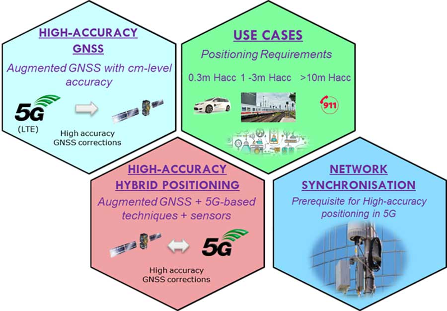
With 5G, this trend of hybrid positioning will accelerate. Multiple GNSS constellation will be employed to increase accuracy, along with localized correction systems. In addition, the 5G cell network will provide additional corrections to enhance the GNSS localization accuracy and to complement GNSS when satellites are not visible.
This 5G “new radio” positioning accuracy will be enhanced by using steerable antennas on both the base station and the user terminal.
The testbed vehicles combined a broad range of on-board systems, incorporating localized high-accuracy correction and LTE 4G and ultra-wide-band terrestrial wireless broadband communication, to measure their positions and share them with one another and perform ongoing vehicle-to-vehicle ranging to simulate future 5G operating standards. (Image: ESA)
And because positioning performance will have to remain at the same high standard as user receivers move around — whether they be people, cars, shared bikes or drones — additional positioning solutions will also be employed, such as inertial sensors or device-to-device relative positioning.
Areas where ESA is contributing to 3GPP standardisation efforts. (Image: ESA)
Miguel Manteiga Bautista, head of ESA’s GNSS Evolution and Strategy Division in the Agency’s Directorate of Navigation, explains, “For the hybrid positioning field-tests, ESA and its partners set up a collaboration with Deutsche Telecom for use of its 4G network in Munich including relevant information for positioning, and NovAtel, who provided state-of-the-art GNSS equipment and correction services, such as the satellite-based TerraStar-X.”
ESA oversaw this initial field test campaign as part of its 5G GNSS Task Force, coordinated with the European Commission and the European GNSS Agency through the Horizon 2020 Framework Programme for Research and Innovation in Satellite Navigation.
The field test campaign was undertaken by DLR and the GMV company, with contributions by engineers from NovAtel, u-blox and Deutsche Telekom as well as ESA.
In 2016 the 5G GNSS Task Force within H2020 took the initiative to shape the support of high-accuracy positioning services in 4G and 5G networks, to contribute to the 3rd Generation Partnership Project, 3GPP, worldwide standardisation effort.
These field tests are executed within the GNSS Integration into 5G wireless networks or GINTO5G project. Undertaken through ESA’s European GNSS Evolution Programme, this project is being is executed by a consortium composed by GMV, Universitat Autonoma de Barcelona (UAB), DLR, u-blox and Telefonica I+D.
Currently, UAB is involved in the thorough processing of all the data gathered during the field test campaign, leading into models and simulation tools and possibly additional field experiments.
This pair of testbed vehicles went out on the road in Germany to simulate the way we are all likely to be using 5G positioning services in the future. (Photo: ESA)