Category: Applications

  • Simulating multipath in real time for receiver evaluation

    By Tommaso Panicciari, Mohamed Ali Soliman and Grégory Moura
    All images provided by the authors

    A real-time system combining a simulator and a GNSS propagation model reproduces an authentic multipath environment. The propagation model relies on a 3D-model reconstruction of the urban environment, which generates a multipath signature strictly dependent on the location of the receiver’s antenna. This yields important results for a moving vehicle, which may be affected by very different multipath conditions depending on trajectory and location.

    Positioning and navigation can be degraded in urban environments by multipath, and the error can increase considerably if not properly compensated. In situations where the line-of-sight (LOS) is obscured by surrounded buildings, the receiver may still be able to navigate by using the non-line-of-sight (NLOS) signal, which originates from single or multiple reflections/diffractions of the GNSS signal.

    The use of 3D models has been one of the preferred solutions to recreate the multipath environment as seen by a GNSS device. This solution brings the capability to generate a multipath signature that is representative of the position of the antenna in a specific time and space. However, this solution comes with a certain degree of complexity. In fact, an accurate 3D model is required to simulate the obscuration of the GNSS signal, and a good propagation model is needed to generate phenomena like reflection and diffraction.

    Figure 1. Example of propagated signal simulation. (Image: authors)
    Figure 1. Example of propagated signal simulation. (Image: Tommaso Panicciari, Mohamed Ali Soliman and Grégory Moura))\

    3D models have become more accurate and widely available and are mainly used to predict the satellite availability in specific locations, for example in evaluating the signal availability in urban canyon, and for both reflection and diffraction. Other uses of 3D models are as an aiding tool to assist navigation, sometimes together with an INS solution.

    In this article, we present a novel real-time system capable of simulating realistic multipath in different environments. The system can simulate multiple GNSS constellations and is comprised of a GNSS simulator interfaced to a propagation model. The system can create a whole range of signals, effects, error models and trajectories in a real-time closed loop. The propagation model controls the simulation of multipath from the interaction of the GNSS signal with the 3D scene and objects. This article describes a novel real-time system for the simulation of realistic multipath in different environments and compares simulated and field-test data. The comparison is based on signal availability, horizontal error, carrier-to-noise (C/N0), pseudorange and Doppler residuals.

    RAY-TRACING WITH 3D MODELING

    The model simulates the propagation of GNSS signals in constrained environments, considering obscurations and multipath. It uses a proprietary ray-tracing kernel (based on bounding volume hierarchy techniques using processing unit [GPU] resources) coupled with geometrical optics and uniform theory of diffraction to compute the interaction between the signal and the local environment. The computation uses as main input a synthetic environment (that is, geometrical and physical modeling of a real or realistic environment) to assess the impact of obscurations related to signal availability issues and multipath (the cause of fading effects and performance problems).

    The objective of ray-tracing is to find all the possible paths from the observer to the source of the signal considering a limited number of interactions per emitted rays. A ray-tracer (or ray-tracing algorithm) uses a primary grid to cast primary rays. Then, it iteratively computes the possible interactions between these rays and the virtual scene (often defined using triangles). If those interactions exist (if they comply with the law of physics) and if the number of interactions to reach the emitter is below the maximum number of interactions set by the user, then a ray (or multipath) is created. This is a deterministic method that can be used to calculate the obscuration due to the local environment (and therefore detect the signal availability) and the geometrical characteristic of the computed path. Combined with physics modeling, path attributes such as received power, delay, Doppler, and phase are also provided.

    The main characteristics of ray-tracing techniques to model GNSS propagation are:

    • All the signals arriving at the receiver can be model-based on the virtual environment.
    • As it is a deterministic method, the more realistic the environment modeling, the more compliant with reality the results. Moreover, the simulation results are repeatable.
    • The specular multipath can be displayed in 3D, and the attributes (for example, receiver power, phase, polarization, Doppler, geometry of the ray) are known. For example, this is relevant when the effect and signature of the environment on the propagation signal need to be studied and understood.

    Nonetheless, ray-tracing techniques must account for three major difficulties:

    They are time-consuming algorithms. Indeed, depending on the complexity of the scene (defined in terms of the number of triangles), a combinatorial problem to find the possible multipaths reaching the receiver makes the ray-tracer very resource-demanding. That is the reason why the most difficult task to achieve during the coding of a real-time ray-tracing algorithm is to develop acceleration techniques to quicken the computation process. Several solutions exist to either improve the intersection determination (for instance, based on spatial hierarchies such as bounding volume hierarchy [BVH] techniques), or to decrease the number of cast rays (often based on adaptive sampling techniques), or even to replace rays with beams or cones. Moreover, it is possible today to use the resources of graphic boards to accelerate the computation. Indeed, as ray-tracing can be coded by a large number of primary functions that can be treated simultaneously, it can be easily ported into GPU.

    Their accuracy depends on the resolution of the primary grid. Details and therefore rays may be missed if the 3D scene is made of small details. This issue is called aliasing. Aliasing artefacts are raised for instance in parts of the scene with abrupt changes (such as edges) or in complex areas with lots of constituent objects. Solutions (or antialiasing techniques) exist to overcome this issue such as adaptive or stochastic samplings.

    When it is combined with geometrical optics, these algorithms only compute the specular rays. Even if some techniques exist to model the scattering signals, only physical optics can render the global signal with high fidelity.

    MULTIPATH SIMULATION SYSTEM

    The proposed system can model two of the main propagation issues encountered in urban environments, such as obscuration (which leads to limitations in signal availability) and multipath (which generates interference that causes fading of the signal and positioning errors). To model realistically such a complex phenomenon, the system uses a GPU ray-tracing algorithm combined with geometrical optics and uniform theory of diffractions. The ray-tracing algorithm relies on 3D-model reconstructions of the urban environment. The computed obscuration and multipath effects are then used to generate signal corrections (in terms of power, delay and Doppler variation) to be used in the GNSS simulator, which generates the carrier, code and navigation messages for different GNSS constellations into a single RF output. Some of the advantages of this system is its ability to run in real time, and to visually show all the reflections/diffractions of the GNSS signals that cause multipath interference.

    Figure 2 shows the diagram of the system set up in conductive mode. The system includes a SE-NAV PC controller, simulator software suite controller, GNSS simulator and device under test (DUT). A different mode is also available called over the air (OTA). This mode uses an anechoic chamber and a set of antennas distributed uniformly to generate the RF signal including the multipath. The DUT can then be placed at the center of the chamber and will be able to receive LOS and NLOS signals from different angles of arrival.
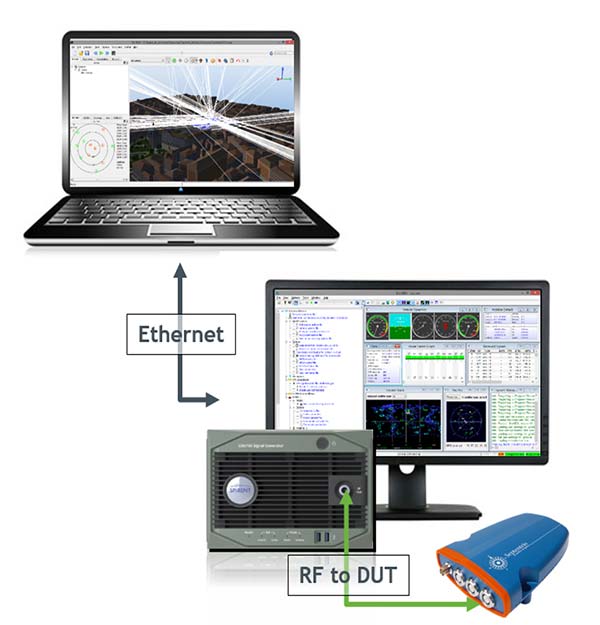
    Figure 2. System diagram that shows propagation simulator controller (top), the GNSS simulator (bottom) and the device under test connected to the RF output of the simulator. (Image: Tommaso Panicciari, Mohamed Ali Soliman and Grégory Moura)

    The GNSS simulator software suite is used to generate and control the generation of the satellite signals (including multipath) at RF, whilst the propagation simulator is used to calculate the propagation information (delay, Doppler and attenuation) of the reflected signals through a 3D urban model. The propagation software is interfaced with GNSS simulator software by means of a package of remote-control facilities that greatly enhances the flexibility of the propagation simulator. Those commands can be sent and received through the transmission control protocol/use datagram protocol (TCP/UDP) with different data streaming rates (10 Hz was used for this article).

    It is also important to point out that the propagation simulator computes all the possible multipath signal generated by the 3D model given the position of the satellites and receiver. However, the physical limitation of the number of channels in the simulator causes the rejection of some rays. This rejection or filtering process can be done according to power (used in this article) or delay.

    EXPERIMENT SET-UP

    A set of different field-test campaigns where carried out in August 2016. Each campaign aimed to evaluate the ability of the system to assess the performances of a GNSS receiver using simulated signals in urban environments. Figure 3 shows the trajectory (blue line) used for the experiment in an urban environment — San Jose, California — with a static (a) and dynamic (b) scenario.
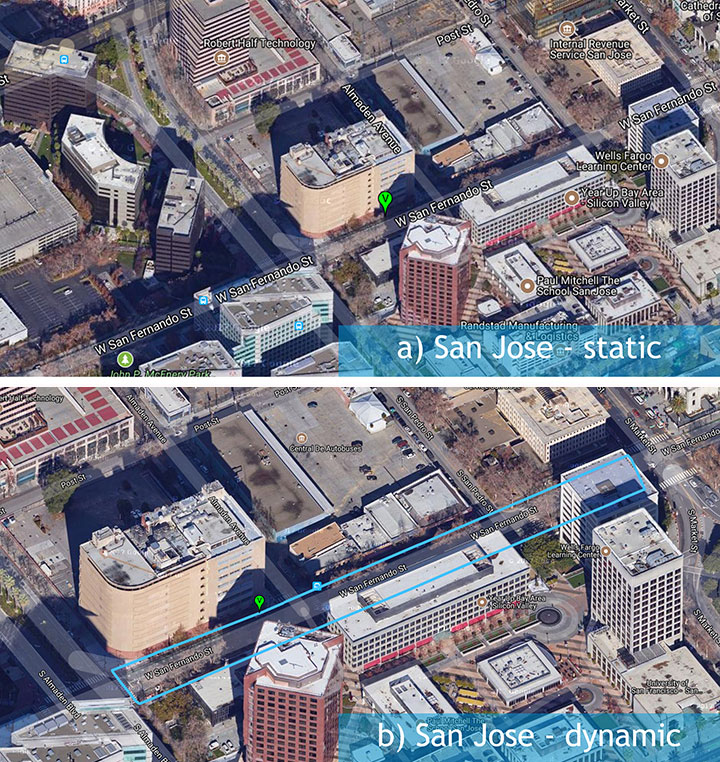
    Figure 3. A set of three measurement campaigns where carried out during Aug. 9–10, 2016: a) urban environment with static antenna; b) urban environment with dynamic antenna. (Image: Tommaso Panicciari, Mohamed Ali Soliman and Grégory Moura)

    Figure 4 shows the 3D scene used to replicate the San Jose urban environment. The buildings in close proximity of the antenna (green area in Figure 4b) contain details like material, 3D facade and windows. In contrast, the buildings far from the antenna were only corrected for height, and the material was modeled as concrete only.
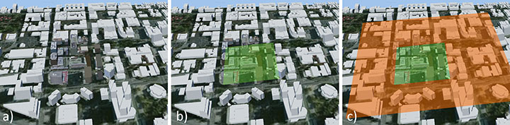
    Figure 4. The San Jose model contained most of the details around the receiver antenna (b), with only height corrected for buildings far from the antenna (c). (Image: Tommaso Panicciari, Mohamed Ali Soliman and Grégory Moura)

    An exception was made for one building in San Jose because its complex architecture was believed to contribute to more reflected rays than would a more simplistic box (concrete) model (Figure 5).
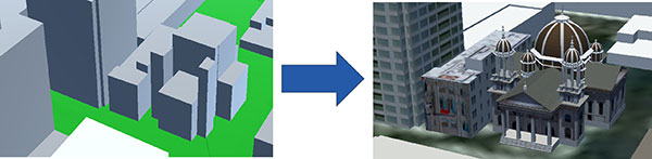
    Figure 5. Improvement (right) in one San Jose building because its complex architecture was believed to generate more reflections than the more simplistic box model (left). (Image: Tommaso Panicciari, Mohamed Ali Soliman and Grégory Moura)

    EXPERIMENT RESULTS

    A direct comparison of C/N0 power, pseudorange residual, and Doppler residual was performed between the field test and simulation.

    San Jose Static Results. Figure 6 shows the results obtained from the San Jose static scenario for satellites PRN02 and PRN06: C/N0 ratio, pseudorange residual and Doppler residual for field test (blue line) and simulation (red line). Although the simulation sometimes creates deeper fading than in the field test, a first comparison indicates a good correlation of simulated data with field-test data.
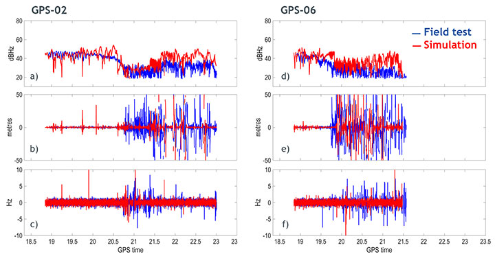
    Figure 6. Carrier-to-noise ratio (top), pseudorange residual (middle) and Doppler residual (bottom) for PRN 02 (left column) and PRN 06 (right column). (Image: Tommaso Panicciari, Mohamed Ali Soliman and Grégory Moura)

    The signature of the multipath caused by this urban environment is visibly captured in the simulation. More interestingly, the pseudorange residuals and, to a lesser extent, Doppler residuals also indicate that the model is replicating the dynamics of the multipath environment in close correlation with the field test.

    Figure 7 shows the C/N0 obtained from the field data (blue), and simulated data (red) with only obscuration (a) and with obscuration and multipath (b) for the static scenario.

    It can be noticed that the receiver can still track PRN02 without the LOS, therefore, relying on just the NLOS signal. This can be clearly seen in Figure 7a where a sudden drop in power is associated to an obscuration of the same satellite (based on our 3D urban model).

    Figure 7b shows the C/N0 obtained from the simulation (red line) when both obscuration and multipath were enabled. In this case the receiver could track the satellite even in the case of only NLOS as in the field test.
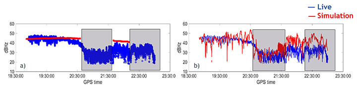
    Figure 7. Carrier-to-noise ratio for satellite PRN02 with only obscuration (a) and with multipath (b). (Image: Tommaso Panicciari, Mohamed Ali Soliman and Grégory Moura)

    The positioning error for the San Jose static scenario is shown in Figure  8a. The simulation and field-test data have a comparable error. The error is relatively big at the beginning of the simulation and decreases after time 20.6. At the time 22.3, a moderate increase in the positioning error is visible in the field data until the end of the test. The simulation also shows a similar trend in this last part of the test, but tends to generate a higher positioning error.

    The satellite availability is shown in Figure 8b for both simulated (red) and field test (blue). The availability of the satellites generated with simulated data is in close relationship with the field data. However, some satellites could not be tracked in the simulation.
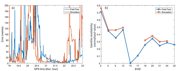
    Figure 8. a) positioning error for field-test (blue) and simulation (red); b) satellite availability for field data (blue) and simulation (red). (Image: Tommaso Panicciari, Mohamed Ali Soliman and Grégory Moura)

    The importance of the accuracy of the 3D scene is evident in this example. In fact, we noticed that one of the buildings that was simulated as a simple concrete box was more complex in the real environment. Therefore, we applied some modifications to scene, as in Figure 9.
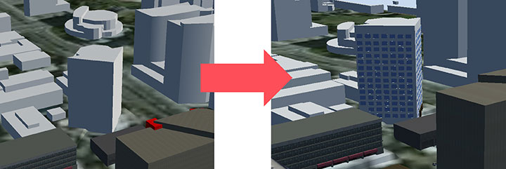
    Figure 9. 3D scene improvement. (Image: Tommaso Panicciari, Mohamed Ali Soliman and Grégory Moura)

    After those changes, a general improvement in the results was visible, but most importantly, the missing satellites could finally be tracked by the receiver (Figure 10).
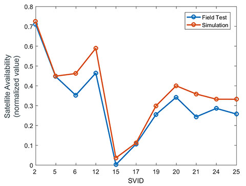
    Figure 10. Satellite availability for field data (blue) and simulation after scene improvement. (Image: Tommaso Panicciari, Mohamed Ali Soliman and Grégory Moura)

    SAN JOSE DYNAMIC TEST RESULTS

    Similar results were obtained with the dynamic test in San Jose. Figure 11 shows the results obtained for satellites PRN12 and PRN24. The walking trajectory included two points where the antenna was stopped because of a traffic light. Those points correspond to a relatively flat C/N0 that can be clearly seen in the field test and simulation data for both PRNs. When, instead, the antenna was moving, a higher variation in the C/N0 is noticeable in both simulation and field test.
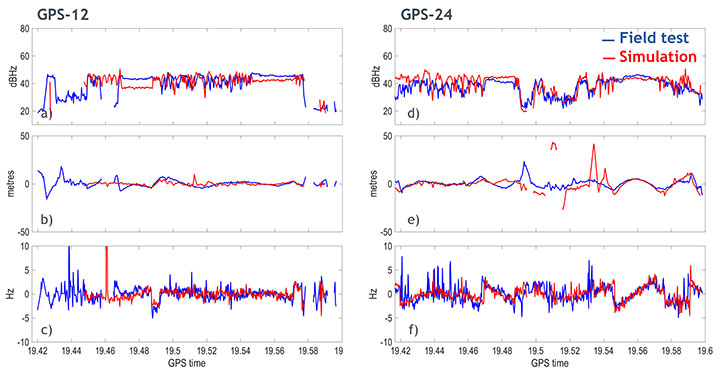
    Figure 11. Carrier-to-noise ratio (top), pseudorange residual (middle), and doppler residual (bottom) for PRN 12 (left column) and PRN 24 (right column). (Image: Tommaso Panicciari, Mohamed Ali Soliman and Grégory Moura)

    Figure 12a illustrates the positioning error obtained from simulated (red) and field test (blue). The first part of the simulation produced an error smaller than the one obtained from field data. However, from the time 19.48, a good agreement can be seen. The satellite availability is also shown in Figure 12b. This last result was obtained with the improved model described in Figure 9.
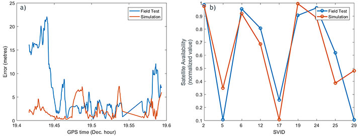
    Figure 12. (a) Positioning error for field-test (blue) and simulation (red); (b) satellite availability for field data (blue) and simulation (red) after scene improvement. (Image: Tommaso Panicciari, Mohamed Ali Soliman and Grégory Moura)

    CONCLUSIONS AND FUTURE WORK

    A new real-time system for multipath simulation is designed to generate realistic multipath that depends on time, position and type of urban environment. The 3D scene is used to calculate the multipath (reflection and diffraction) caused by the buildings and objects around the antenna.

    Some first results demonstrated that realistic multipath can be generated by simulating reflections and diffractions even with a simple 3D model. However, the inclusion of finer details in the model can improve the simulation and make it even closer to reality.

    As always, simulation interest is a tradeoff between reliability in all conditions and efforts to adapt (that is, to specify) a generic and simple model. The added value of our model consists in its simplicity and its good compliance with field data.

    Ray-tracing techniques coupled with geometrical optics and uniform theory of diffraction are efficient and simple methods to simulate the propagation of GNSS signals in complex urban environments. Their efficacy is demonstrated by a good agreement between simulation and field measurements. Some discrepancies still exist and are due to the limitations of such a model:

    • The accuracy of the model is never perfect and, as ray-tracing is a deterministic method, the returned results strongly depend on the quality of the input data used to generate the model.
    • Geometrical optics is a simple (but efficient) method. Only specular rays are modeled, thus the system won’t be able to generate all the signals coming from other phenomena such as scattering. Another limitation is given by the hardware. In fact, the number of simulated multipath depends on the number of available channels in the simulator.
    • The simulation parameters try to mimic the field conditions. However, the simulated trajectory is approximated, and other factors like pedestrian motion, vegetation (isolated trees or forest) and traffic may contribute to reduce some of the discrepancies that can be observed between simulation and field

    All of these limitations can explain the differences between simulated and measured data. Currently, the impact of vegetation (forest and/or isolated trees) models, pedestrian motion and traffic on the multipath signal can also be simulated and their performances are under evaluation.

    ACKNOWLEDGMENTS

    We thank Colin Ford and Ajay Vemuru from Spirent Communications and Antoine Boudet, Yann Dupuy, Arnold Duquesne and Paul Pitot from OKTAL Synthetic Environment.

    MANUFACTURERS

    The system described in this article consists of a Spirent GNSS simulator equipped with a SimGEN software suite and the SE-NAV simulator developed by OKTAL Synthetic Environment. SE-NAV is interfaced with SimGEN via the SimREMOTE protocol, a real-time control and motion API.


    Tommaso Panicciari obtained a Ph.D. in telecommunications from the University of Bath (UK). He is a software/project engineer at Spirent Communications where his main activity focuses on spoofing and multipath simulation.

    Mohamed Ali Soliman is completing a master’s degree in telecommunications with business at University College London. He is a product manager at Spirent Communications, managing multiple products including the multipath simulation offering.

    Grégory Moura graduated from the French Institute of Aeronautics and Space with an M.S. in cosmology from Université de Toulouse. He manages the GNSS activities of the French company OKTAL Synthetic Environment.
  • Hemisphere GNSS debuts Atlas-capable smart antennas

    Hemisphere GNSS debuts Atlas-capable smart antennas

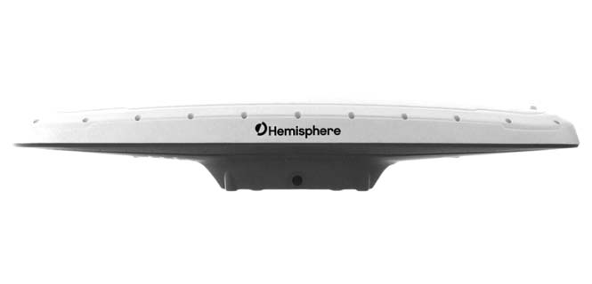
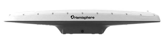
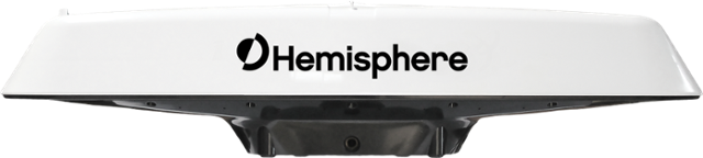
    The Hemisphere GNSS Vector V123 smart antenna.

    Hemisphere GNSS has released the new single-frequency, multi-GNSS Vector V123 and V133 all-in-one smart antennas with integrated Atlas L-band designed for professional and commercial marine applications.

    The company made the announcement at the Oceanology International conference being held this week in London, U.K.

    Powered by Hemisphere’s Crescent Vector technology, the new V123 and V133 are multi-GNSS compass systems using GPS, GLONASS, BeiDou, Galileo and QZSS for simultaneous satellite tracking to offer heading, position, heave, pitch and roll. Both antennas support NMEA 0183 and NMEA 2000.

    The V123 and V133 thrive in radar/ARPA, AIS, ECDIS, side-scan survey, multi- and single-beam surveys, dredging and general navigation applications.

    The V123 and V133 rugged smart antennas combine Hemisphere’s recently announced Crescent Vector H220 OEM board and two superior multipath- and noise-rejecting antennas (spaced 50 centimeters  apart) in a single enclosure.

    The smart antennas require only a single power/data cable connection for fast and reliable installations, even in the presence of strong radio transmissions. Both Vector models provide 0.3-degree heading accuracy and sub-meter DGPS accuracy, as well as optional 0.5-meter Atlas L-band accuracy.

    The V133 includes all the features of the V123 and adds the capability of receiving differentially corrected data from land-based beacon stations. Ease of installation and no maintenance or servicing enhances the simplicity of these new Vector models.

    “The Vector V123 and V133 GNSS compasses represent significant enhancements to our industry leading models they replace, providing even greater performance, improved robustness and excellent value,” said Miles Ware, director of marketing at Hemisphere GNSS. “Users now have an even higher performing all-in-one Vector for their commercial and professional needs with the addition of BeiDou, Galileo, and QZSS as well as Atlas L-band corrections.”

  • Hemisphere GNSS offers Atlas-capable GNSS receiver for marine applications

    Hemisphere GNSS offers Atlas-capable GNSS receiver for marine applications

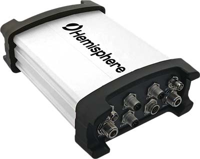
    Hemisphere GNSS has introduced the Vector V1000 GNSS receiver for precision marine applications. The V1000 provides high-accuracy heading, position, pitch, roll and heave data.

    The company made the announcement at the Oceanology International conference being held this week in London, U.K.

    The V1000 supports multi-frequency GPS, GLONASS, BeiDou, Galileo, QZSS and IRNSS (with future firmware upgrade and activation) for simultaneous satellite tracking. The receiver is powered by Hemisphere’s Athena real-time kinematic (RTK) engine and is Atlas L-band capable.

    The new V1000 is designed for professional marine applications, such as hydrographic and bathymetric surveys, dredging, oil platform positioning, buoys and other applications that demand the highest level 3D positioning accuracies. Based on Hemisphere’s Eclipse Vector technology, the V1000 uses the most accurate differential corrections including RTK and Atlas L-band.

    The V1000 is Hemisphere’s flagship receiver, with an integrated display, that can be conveniently installed near the operator. The two antennas can be installed at user-specified separation, providing valuable flexibility in terms of install locations and desired heading accuracy.

    The V1000 has heading accuracy of better than 0.01 degree when using a 10-meter antenna separation. With CAN, serial, Bluetooth, Wi-Fi and Ethernet support and flexible installation, the all-new rugged enclosure gives the V1000 the advantage of working reliably in harsh environments, the company said.

  • New report predicts small drone threats to infantry units

    The emergence of inexpensive small unmanned aircraft systems (sUASs) has led to adversarial groups threatening deployed U.S. forces, especially infantry units, according to a new report.

    Although the U.S. Army and the U.S. Department of Defense (DOD) are developing tactics and systems to counter single sUASs, the report by the National Academies of Sciences, Engineering and Medicine emphasizes the need for developing countermeasures against multiple sUASs — organized in coordinated groups, swarms, and collaborative groups — that could be used much sooner than the Army anticipates.

    The committee that conducted the study developed a classified report that details its findings and recommendations, along with an unclassified public version that discusses key background issues.

    “Hobby drones are easy to buy, their performance is improving dramatically, and their cost has dropped significantly; now with millions of them around the world, they pose a growing threat to the U.S. warfighting forces if used for nefarious intents,” said Albert Sciarretta, president of CNS Technologies and chair of the committee. “The threats could be consumer items like hobby drones, modified consumer items such as could be assembled with online components, and customized ones, like built-from-scratch aircraft.”

    The committee that authored the report was asked by the U.S. Army to assess the threat from sUASs, especially when massed and operating collaboratively, examine the current capabilities of military units to counter them, assess related human performance issues, and identify technologies appropriate for short- and long-term science and technology investments by the Army.

    Readily available, high-performance, sUASs can be easily modified to carry lethal weapons, identify targets at long ranges, and conduct electronic warfare attacks. As the capabilities of hobby drones improve at a rapid pace, the added threat from coordinated groups, swarms and collaborative groups of sUASs will pose a substantial challenge to U.S. armed forces, the report says.

    “Modified hobby drones can be used to support conventional and unconventional attacks. For example, they can be fitted with external or embedded explosives designed to explode on contact,” added Sciarretta. “In addition, they can be used by adversaries to jam our radio frequency signals and to support their information operations. When these sUASs are combined in groups or swarms, their threat is significantly enhanced.”

    Countering sUASs first requires detection and identification, which is difficult because they are small, fly at low altitudes, can have highly irregular flight paths, and travel at a range of speeds, the report says. Moreover, a sUAS can also take advantage of the surrounding environment, for example, by concealing itself among trees or blending in with a flock of birds.

    Even after threats are identified, countering sUASs can be challenging, the report says. The Army and DOD have invested significantly in technologies in response to these threats, often focusing on detecting radio frequency transmissions of the sUASs or their operators.

    However, the report highlights that today’s consumer and customized sUASs increasingly can operate without radio frequency command-and-control links by using automated target recognition and tracking, obstacle avoidance, and other capabilities enabled by software.

    The study was sponsored by the U.S. Army.

    Copies of Counter-Unmanned Aircraft System (CUAS) Capability for Battalion-and-Below Operations are available from the National Academies Press or by calling 202-334-3313 or 1-800-624-6242.

  • Lockheed Martin’s JASSM-ER declared operational on F-15E Strike Eagle

    Lockheed Martin’s JASSM-ER declared operational on F-15E Strike Eagle

    Lockheed Martin’s Joint Air-to-Surface Standoff Missile (JASSM) – Extended Range (ER) achieved full operational capability on the F-15E Strike Eagle, flown by the U.S. and allied nations’ air forces.

    With completion of integration and the fielding of JASSM-ER’s Suite 8 Operational Flight Program, the F-15E Strike Eagle becomes the first Universal Armament Interface (UAI)-compliant platform to field JASSM-ER. UAI-compliant aircraft feature standardized interfaces to support future weapon integration.

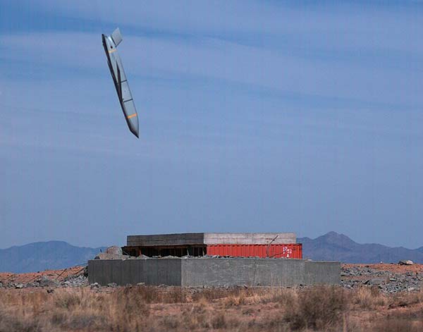
    Like the JASSM, the JASSM-ER cruise missile employs an infrared seeker and enhanced digital anti-jam GPS to dial into specific points on targets.

    JASSM employs an enhanced digital anti-jam GPS receiver and infrared seeker to dial into specific points on targets. (Photo: Lockheed Martin, courtesy of the U.S. Air Force)

    “Fielding on the F-15E Strike Eagle expands JASSM-ER’s mission flexibility,” said Jeffrey Foley, program director of Long-Range Strike Systems at Lockheed Martin Missiles and Fire Control. “With its greater than 500 nautical-mile standoff range and planned block upgrades currently in work, JASSM-ER provides an impressive tactical advantage for U.S. and allied warfighters.”

    Baseline JASSM was the first missile ever to be integrated onto a UAI platform. The U.S. Air Force Seek Eagle Office led the F-15E Strike Eagle JASSM-ER and JASSM integration.

    Armed with a penetrating blast-fragmentation warhead, JASSM-ER and JASSM can be used in all weather conditions. They share the same powerful capabilities and stealth characteristics, though JASSM-ER has more than two-and-a-half times the range of JASSM for greater standoff distance.

    Effective against high-value, well-fortified, fixed and relocatable targets, JASSM-ER is integrated on the B1-B and in the process of integration on the F-16C/D and the internal bay and wings of the B-52H. JASSM is integrated on the U.S. Air Force’s B-1B, B-2, B-52, F-16 and F-15E.

    Internationally, JASSM is carried on the F/A-18A/B, F-18C/D and F-16 Block 52 aircraft.

    Produced at the company’s manufacturing facility in Troy, Alabama, more than 2,150 JASSMs have been delivered.

  • Taoglas launches rugged antennas for automotive, drone markets

    Taoglas launches rugged antennas for automotive, drone markets

    Taoglas, a provider of IoT and automotive antenna and RF solutions, has introduced its patent-pending Terrablast range of antennas.

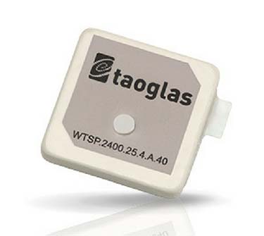
    The Taoglas Terrablast antenna line is designed for UAVs and transportation. (Photo: Taoglas)

    The polymer-based patch antennas are 30 percent lighter than their ceramic counterparts and extremely resistant to fracture upon impact. Terrablast antennas are designed for the automotive and unmanned aerial vehicle (UAV) markets, where impacts are possible but antenna performance cannot be compromised.

    Unlike traditional patch antennas, which are ceramic, Terrablast uses a new class of Taoglas polymer dielectric material composed of glass-reinforced epoxy laminate. The addition of the polymer to the blend makes the antenna extremely lightweight, yet impact resistant, the company said.

    The Terrablast antennas are designed to withstand drops, falls and impacts, and are designed for applications such as UAVs, where the antenna’s mechanical robustness following potential impact is critical.

    The Terrablast patch antennas are also typically 30-35 percent lighter than traditional patches. In drone applications, where weight over battery life is critical — each gram reduced enhances battery life.

    “Taoglas is leading the charge in material science advancement for the antenna industry, and our new Terrablast antennas are the latest innovation we’re introducing to the market,” said Ronan Quinlan, co-CEO and co-founder of Taoglas. “A variety of industries and applications, especially the automotive and drone markets, will benefit from Terrablast’s high-performance capabilities in a lightweight, impact-resistant form factor.”

    The first antennas in the Terrablast range are a 25-mm embedded 2.4 GHz patch antenna and a 35-mm embedded GPS patch antenna. The circular polarized design of the 2.4-GHz patch ensures maximum performance for constantly moving mobile applications where the orientation to the transmitter or receiver frequently changes. The antenna weighs 5.6 grams compared to an equivalent ceramic patch of 8.5 grams, providing a weight-saving substitute for ceramic patches in UAV applications.

    The 35-mm GPS/GLONASS/BeiDou patch antenna has extremely high efficiency of more than 70 percent across all bands, improving time to first fix. At 10 grams, the 3.5-mm-thick patch is 5.5 grams lighter than typical ceramic GNSS patches.

    All Terrablast antennas undergo rigorous temperature, vibration and impact tests, exceed the highest ISO 16750 standards, and are manufactured in Taoglas’ purpose-built facilities in Taiwan and the United States.

  • SkyTraq introduces GPS/GAGAN receiver module for Indian market

    SkyTraq introduces GPS/GAGAN receiver module for Indian market

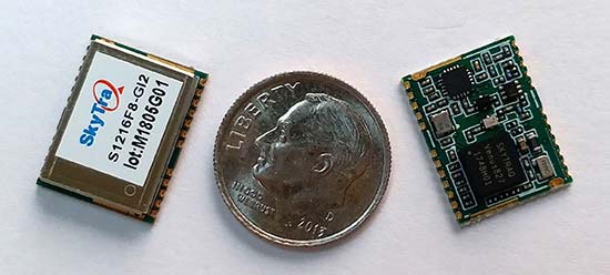
    SkyTraq Technology Inc., a fabless GNSS positioning technology company, has introduced the S1216F8-GI2, a NavIC + GPS/GAGAN receiver module for the emerging Indian market.

    It integrates L1/L5 RF front-end and baseband processor capable of receiving up to 14 L5 NavIC signals and up to 20 L1 GPS/GAGAN signals simultaneously. With currently usable six NavIC signals and three GAGAN signals, it offers a total of 18-23 usable signals for navigation compared to 9-14 usable signals with conventional GPS receivers, providing improved accuracy in urban canyon environments with signals often blocked by high buildings.

    The S1216F8-GI2 has form-factor and pin-out compatability with popular 12 x 16-millimeter GPS receiver modules, so customers using those GPS modules can effortlessly migrate to NavIC/GPS capability by drop-in replacement and changing to an L1/L5 antenna.

    For emerging intelligent transport systems (ITS) applications requiring NavIC/GPS capability in India, S1216F8-GI2 enables fast time-to-market for product manufacturers, the company said.

    NavIC sub-frame data output is a useful feature of the S1216F8-GI2. It can output NavIC broadcast warning messages related to weather alerts, forecast, and natural disasters such as cyclones, earthquakes and tsunamis.

    An S1216F8-GI2 engineering sample, evaluation kit and datasheet is available. Volume delivery to customers begins in late March. The S1216F8-GI2 is manufactured with ISO/TS 16949 automotive certification.

  • Hemisphere GNSS launches Vector V500 GNSS compass smart antenna

    Hemisphere GNSS launches Vector V500 GNSS compass smart antenna

    Hemisphere GNSS has released its RTK-enabled Vector V500 smart antenna. The company made the announcement at the Oceanology International conference being held this week in London, U.K.

    The V500 supports multi-frequency GPS, GLONASS, BeiDou, Galileo, QZSS and IRNSS (with future firmware upgrade and activation) for simultaneous satellite tracking. The V500 is powered by Hemisphere’s Athena RTK (real-time kinematic) engine and is Atlas L-band capable.

    Using Hemisphere’s Eclipse Vector technology, the all-in-one V500 is a complete compass system that offers GNSS-based heading, pitch, roll, heave and RTK positioning, the company said.

    The V500 introduces support for Ethernet, Bluetooth and Wi-Fi in addition to NMEA 0183 and NMEA 2000 and offers unmatched ease of installation.

    Purpose-built for challenging applications, the V500’s rugged enclosure works reliably in harsh environments and is designed for professional marine applications requiring high-precision heading combined with RTK or Atlas positioning.

    The V500 is Hemisphere’s flagship rugged smart antenna. It combines the recently announced Eclipse Vector H328 OEM board with two superior multipath- and noise-rejecting antennas (spaced 50 cm apart) in a single enclosure.

    The V500 requires a single power/data cable connection, allowing for fast and reliable installations even in the presence of strong radio transmissions.

    According to Hemisphere GNSS, the V500 delivers 0.17 degree heading accuracy along with RTK positioning and Atlas L-band accuracies of up to 8 cm (95 percent).

    “The Vector V500 combines our expertise in GNSS, smart antenna design, and our new technology features such as Atlas,” said Lyle Geck, senior product manager at Hemisphere GNSS. “With very competitive RTK performance and the simplicity of installation offered by the all-in-one smart antenna design, it is an incredible product.”

    Atlas GNSS Global Correction Service. Atlas is a flexible and scalable GNSS-based global L-band correction service providing robust performance and correction data for GPS, GLONASS and BeiDou, the company said. Atlas delivers correction signals via L-band satellites to provide accuracies ranging from sub-meter to sub-decimeter levels, and leverages approximately 200 reference stations worldwide, providing coverage to virtually the entire globe.

    Atlas is available on all Hemisphere Atlas-capable single- and multi-frequency, multi-GNSS hardware and complements third-party GNSS receivers by using Atlas corrections with Hemisphere’s SmartLink and BaseLink capabilities. Atlas creates fast convergence times, and is robust and reliable near wharfs, piers, offshore rigs, cranes and other overhead obstructions.

    Atlas Basic provides users of both single- and multi-frequency Atlas-capable hardware the ability to achieve better than SBAS performance anywhere Atlas correction service is available. Atlas Basic offers accuracy of 30 cm (pass-to-pass 95%) to 50 cm (absolute 95%) and offers instantaneous sub-meter accuracy.

    The Vector V500 is featured in the Hemisphere GNSS booth (G500) at the Oceanology International exhibition and conference in London, UK, March 13-15. The new V500 will be available soon through Hemisphere’s global dealer network.

  • Aerosense surveying drone markers use u-blox positioning

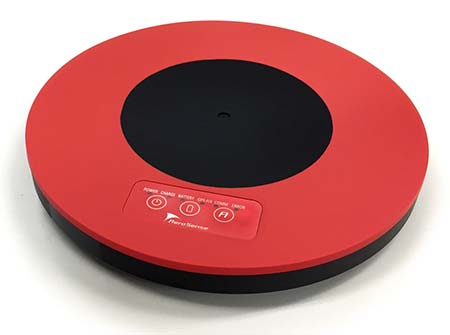
    Japan-based Aerosense Inc. has commercialized its AEROBO marker solution for drone surveying using the u‑blox NEO‑M8T timing module.

    Photo: Aerosense
    Photo: Aerosense

    Conceived to compute absolute time to within 20 nanoseconds using incoming GNSS signals, the NEO-M8T lets users access raw GNSS data output, making it attractive for positioning applications that rely on post-processing GNSS data to enhance location accuracy.

    Aerosense’s surveying solution is designed to reduce the time spent surveying construction sites. By combining ground markers equipped with a GNSS receiver with surveying drones and cloud-based data processing, Aerosense has converted huge workloads into a user-friendly application.

    The surveying operation on the site involves setting up ground markers fitted with u‑blox NEO‑M8T high-performance GNSS receivers. The smart ground markers send the GNSS data they receive to the cloud, where it is post-processed using a static surveying algorithm to achieve high accuracy.

    The AEROBO solution can transform high-resolution drone images into a survey-accurate map by using the absolute geographic coordinates of specific points on the surveyed terrain. Images gathered by overflying the terrain with the drones are combined to create centimeter-precise outputs, including orthomap views, 3D models and point clouds.

    The challenge that engineers at Aerosense faced while developing their solution was achieving sufficiently high position accuracy. “We found a robust solution to the accuracy challenge by using the u‑blox NEO‑M8T high-performance positioning module,” said Satoru Shimizu, project leader of AEROBO technology development at Aerosense.

  • Geneq introduces SXblue Premier GNSS receiver

    Geneq introduces SXblue Premier GNSS receiver

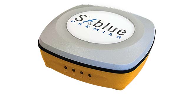
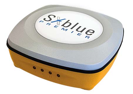
    Geneq has launched the SXblue Premier GNSS receiver, which is available in a submetric version (GNSS) or centimetric version (real-time kinematic, RTK).

    The new SXblue Premier GNSS receiver is equipped with the Pacific Crest Maxwell 6 Trimble technology with BD910 (GNSS version) and BD930 (RTK version) OEM boards, delivering 220 channels to acquire and track GNSS signals from all constellations in view. It makes effective use of GPS, GLONASS, Galileo, BeiDou, QZSS and SBAS signals for outstanding highly precise positioning.

    The SXblue Premier is small and light weight, and rugged for field work. It is equipped with dual mode for Bluetooth V2.1 and Bluetooth V4.0, ensuring the unit’s wireless communication with any Android or Windows terminal. With its two models, the user will have large efficiency and flexibility on the field either with SBAS corrections or RTK reference networks.

    In addition, SXblue Premier can be configured for Wi-Fi hotspots, allowing users to connect and access a web management platform. It also can be used as a data link, providing a quick connection to the internet to receive corrections from reference station (CORS) networks so that it can process RTK measurements.

    With its internal memory using an 8-GB solid state disk, SXblue Premier provides enough storage space for field data collection or raw data recording for a high data sampling rate.

    Multiple compatible software programs — including FieldGenius, Carlson, Collector for ArcGIS — will meet the users’ diverse need, making SXblue Premier more powerful and flexible.

  • GPS, surveyors and politics — a 2018 refresher

    GPS, surveyors and politics — a 2018 refresher

    While not as glamorous as mild-mannered Clark Kent holding down a day job while Superman comes to the rescue in time of crisis, there are professional surveyors who work day jobs to perform our duties as practitioners to make a living and participate in association activities in their off-hours to help promote and protect their profession as well as the public they serve.

    Many of the hours spent to protect the profession are in the political arena, where the battle for budget dollars and service rights are fought on nearly a daily basis. Because of the reliance of the surveyor on technological advances, the profession has been thrust into the political arena at all legislative levels. The surveyor has been tasked with leading the discussion and help the public understand why significant dollars are needed for funding many different programs to continue with our high-tech trends and lifestyles.

    Three of the four presidents on Mount Rushmore started as surveyors — George Washington, Thomas Jefferson and Abraham Lincoln. (Photo: National Park Service)

    The role of the surveyor has not been considered political even though several significant U.S. presidents were surveyors in their early careers. Surveyors aren’t particularly known for their public personas, much less their political prowess. Other than states that still have county surveyors, rarely do practitioners stray beyond local municipal government. One is more likely to see a professional engineer or architect as an elected official than a surveyor, but that doesn’t mean the issues we face are any less important.

    My current position is a professional land surveyor with a full-time job overseeing a department in a multi-discipline office in a major metropolitan area. Besides being a contributing editor to GPS World through these articles, I also voluntarily wear many hats within our state association and the national surveying society. Several of these hats are government affairs positions at both state and federal levels, as it has become a full-time operation to keep a watchful eye at all governmental levels. From changes in regulations, budgetary revisions and threats to our professionl by outside entities, government affairs take a small army of people to keep abreast of all situations.

    This month’s submission is just a snapshot of the current National Society of Professional Surveyors (NSPS) Joint Government Affairs Committee action item list being addressed and monitored through its committee members and a governmental lobbyist. The importance of this list is to give the reader a sampling of the seemingly endless battles being waged on Capitol Hill by NSPS and its members nationwide.

    All these issues have GNSS at their heart and will have dire consequences if any of these subjects fall short of their intended marks.

    This is not just about the GNSS and how we collect data; it’s also about the necessity of large scale data collection to provide better and safer services to the citizens of the United States and its territories.

    Our current datasets and standards for data collection, like our infrastructure, is aging and lacking in detail. Serious upgrades are overdue, so several actions have been put forth to try to rectify the shortcomings.

    3DEP

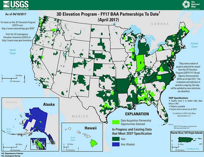
    Formally known as the 3D Elevation Program, this language was introduced as part of S. 1460 (“Energy and Natural Resources Act of 2017”) by Senator Lisa Murkowski of Alaska. This program is being created so that consistent elevation data, cultivated through many surveying and mapping sources including lidar, will be available for efficient design use throughout the American infrastructure.

    While it currently does not have a single line item in any budget, the USGS Budget Summary lists its necessity in the Core Science Systems Program as part of the National Geospatial Program. This program is intended to provide high-quality topographic, geologic and hydrographic data nationwide to assist with further development of energy, transportation, drainage, emergency response and hazard mitigation.

    As part of the 2019 President’s Budget, the USGS Green Book also lists having the entire nation covered by an ongoing lidar program by 2033, along with completing a significant amount of data collection by various means in Alaska by 2022, including high-resolution interferometric synthetic aperture radar (IfSAR) necessary for data collection in more difficult terrain.

    The Green Book also lists high-resolution hydrographic data to support flood risk management studies, as the frequency of large scale flooding seems to be increasing substantially in more places than ever before. It also includes additional mapping data, programming and functionality for emergency personnel charged with oversight of public safety in times of crisis.

    FAA reauthorization

    The current FAA authorization bill expires on March 31. The biggest hang up holding up getting the bill reauthorized is privatization of the air traffic controllers, but there are rumors of tightening of UAV rules due to the rapidly growing use of the vehicles for business and personal use.

    Surveyors are working with federal and state officials to help implement reasonable rules for use and coverage of the UAV as the field of surveying has been drastically affected by use of aerial vehicles. Many tasks that used to take days now take hours with increase accuracy, so the effects of the UAV will be seen for many years to come.

    Digital Coast Act

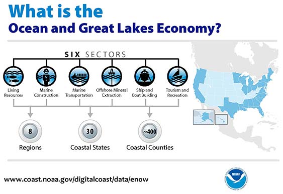
    One of the legislative acts that NSPS was a big part of in 2017 was Senate Bill 110, “The Digital Coast Act” which led to the introduction of the companion bill in the House as H.R. 4062. This Act will allow NOAA to perform the necessary actions to actively and effectively monitor all coasts (including the Great Lakes) by various means, including bathymetric and conventional survey methods. This will require services to be performed by public and private surveyors primarily with GNSS capability to provide NOAA with standardized information based upon established datum.

    FLAIR Act

    The Federal Land Asset Inventory Reform (FLAIR) Act of 2017 was introduced as House Resolution 2199 to help with creating a database of government property nationwide. The Government Accountability Office (GAO) has stated that the management of federal real property has become a “high-risk” item on its list of duties. Management of the number and value of properties has increased to a point that an overall dollar amount of federal buildings and land cannot be accurately determined.

    How does the surveyor fit in with this issue? Simple. The U.S. government will need to upgrade its database of existing facilities through having them surveyed for asset management. Part of the requirements for providing these surveys will be completing the work in datums that will be following the geographical databases being designed to contain the parcel and building information. All this data will have geospatial information regarding parcel, address, utilities and functionality of the inventory, so providing the data with the sufficient attributes will become a key role for the surveyor. GNSS data collection will be at the heart of this monumental task.

    Geospatial Data Act

    As introduced in May 2017, the Geospatial Data Act (GDA) of 2017 is intended to jumpstart the nationwide initiative to develop and coordinate efforts to collect and maintain new datasets of elevation and infrastructure information. It is intended to improve and enhance federal geospatial activities to encourage state and local agencies to participate at the local level.

    It is interesting to note, however, that the revised Geospatial Data Act was introduced by the same sponsors that did not include procurement procedures that follow the typical Brooks Act of quality-based selection, and instead relied on bid-based selection commonly found with suppliers. Both bills are being vetted by their sponsors and potential geospatial providers for clarity with ongoing debate going forward.

    Hydrographic Services Improvement Act

    H.R. 211 bring us the Hydrographic Services Improvement Act to provide NOAA with incentive and funding to standardize surveys desperately needed in waterway areas. Ongoing discussion continues this spring to determine sources of funding and priority of projects.

    Infrastructure bill

    February brought us the introduction of a significant infrastructure program aimed at improving roads, airports and bridges, with other major improvements across the country. This program is noteworthy in recognizing the need of current geospatial data and inventory of major infrastructure needs. The program sets forth the need for surveying, mapping and geospatial data for planning, design, construction, operations and maintenance for a multitude of projects nationwide. Much more will be discussed regarding the funding and priority of projects as the political year moves on.

    LightSquared/Ligado

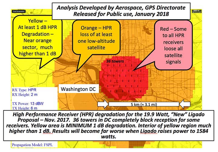
    Readers may remember when the original confrontation with LightSquared began in 2011, and the subsequent battle over the frequency ranges adjacent to the GPS bandwidth. The FCC gave LightSquared initial but conditional approval to move forward with terrestrial-based transmission for 4G cellular transmission for up to 40,000 land-based stations. Testing by private and governmental agencies through 2011 and 2012 proved that LightSquared would greatly harm GPS activity for both public and private use. Once exposed, the conditional FCC approval was rescinded and LightSquared retreated into the shadows…until now.

    Reformed as Ligado, it has fresh investors and is making a charge into 5G technology with a revised game plan. While it is also looking to use other spectrums for communication, it once again is dangerously close to other current uses. Couple the proximity of adjacent bandwidth with the intense land-based signal versus a very weak satellite signal, there will be significant overriding by the new user. All of this is still being worked out through the FCC and the Department of Defense, so final resolution is yet to be seen.

    IMAGES Act

    The National Flood Insurance Program (NFIP), as part of FEMA, is looking to move forward with legislation introduced as Improvement of Mapping, Addresses, Geography, Elevations and Structures (IMAGES) Act (H.R 4905). This act intends to reform the NFIP program by utilizing new elevation data collected through the 3DEP program, which will be combined with other parcel attributes including addresses and structure types. This data will then be combined with refined floodway information to identify parcels that are more susceptible to damage caused by storms and flooding.

    New legislation can be a good thing, but only if funding can be provided. This bill could provide a major upgrade to the flood mapping and insurance program, but it will hit a big snag with lack of monetary support. The proposed funding for FY2019 is $100 million, yet the project costs for the FY2018 budget is $178 million. This significant difference will make a large impact on the effectiveness of the program and proposed revamp.

    Railroad reauthorization

    NSPS has spent several years working with various legislators trying to find the right bill to insert language to require railroads to monument their routes before removing tracks. But with the recent accidents of various rail lines, the spotlight has been put on various factors that cause the incidents and how to eliminate their occurrence.

    Positive train control (PTC) systems incorporate geospatial data collected through GNSS, lidar and conventional surveying means to work with operational systems to assess dangerous situations. Surveyors will need to be at the forefront of the necessary data collection so our efforts to continue lobbying for railroad funding will continue.

    Net Neutrality Act

    A political hot topic the surveyor doesn’t typically think about is net neutrality. Most people think they will be affected by lack of neutrality slowing down their home internet or streaming service, but for surveyors it will be a much bigger deal.

    A remarkable number of surveyors and mappers use cellular data streaming to provide a connection to a positional correction service. The throttling of this data will effectively slow down the performance and quality of the positional data, leading to less reliability and productivity. It will also slow down the data interaction of office and field staff exchanging data and image files critical to project productivity and success.

    So, when the call goes out to contact your federal representative to protect net neutrality, remember how it will affect your surveying business model and make that call.

    How professional land surveying associations get it done

    Many thanks to the countless hours put in by the NSPS Joint Government Affairs team, consisting of Committee Chair Pat Smith, NSPS Government Consultant John Palatiello, NSPS Federal Lobbyist John “JB” Byrd and NSPS Executive Director Curt Sumner. This group is constantly monitoring legislative action across the country as well as in D.C. and is quick to respond when action is needed on legislative issues. They do a tremendous job, yet not many see them in action. Hopefully all surveyors will continue to see and feel the benefits of their results.

    As simple as the process is, the political world has gotten much more complicated as time marches on. From local municipal offices to Washington, D.C., getting things done through legislation has become a long process that takes patience and plenty of money to get your voice heard. Surveyors are no different than any other profession in that we must stay out in front of issues that affect our physical and business world. The important part is to stay informed and have a voice.

    Let’s also remember those three fine individuals, memorialized on Mount Rushmore, who accomplished great things after their stints as  surveyors, so anything is possible if we keep our voice in government.

    Surveying has evolved into a highly technical professional with GNSS as a backbone method of data collection. With the U.S. government at the center of that technology, we need to make sure we, as the surveying practitioner, stays engaged.


    Featured photo: National Park Service

  • NovAtel test drives STMicroelectronics’ Teseo APP and Teseo V chipset

    NovAtel test drives STMicroelectronics’ Teseo APP and Teseo V chipset

    NovAtel has integrated its high-precision positioning engine and correction services with automotive-grade multi-frequency GNSS chipsets from STMicroelectronics: specifically, the Teseo APP (Automotive Precise Positioning) and Teseo V.

    The integration demonstrates possibilities for vehicle localization solutions. NovAtel is part of Hexagon’s Positioning Intelligence Division.

    STMicroelectronics’s Teseo APP and Teseo V provide multi-frequency GNSS data for PPP (precise point positioning) and RTK (real-time kinematic) for accurate positioning capabilities.

    The Teseo APP features built-in integrity checking for use in safety-critical systems, whereas Teseo V is used for non-safety-critical precise positioning applications.

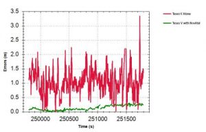
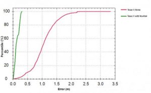
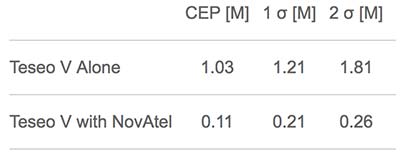
    The Teseo V SBAS and Teseo V NovAtel PPP tests took place in a light urban environment. (Image: NovAtel)

    NovAtel’s positioning engine combines the GNSS measurements from these chipsets with inertial measurement unit (IMU) data and Hexagon PPP correction services on the demonstration platform to deliver centimeter-level PPP positioning solutions in real time.

    “Working closely with STMicroelectronics using their Teseo APP chipset allowed us to innovate and speed up the development of our assured positioning solution tailored specifically for safe positioning of autonomous vehicles,” said Jonathan Auld, VP Engineering and Safety Critical Systems from NovAtel.

    NovAtel’s positioning engine architecture enables a flexible integration with different GNSS receiver chipsets, IMUs and processor environments, providing automotive manufacturers with additional flexibility when it comes to selecting components and subsystems of advanced driver assistance systems (ADAS) and autonomous driving solutions.

    The positioning engine is being developed to ASIL-B standards according to ISO26262 and will include a proprietary GNSS integrity solution to ensure safe positioning within defined protection limits that are tailored to the customer’s application requirements.

    “NovAtel’s choice of the automotive-quality ASIL-capable Teseo APP to integrate with their GNSS positioning engine is enabling them to develop a world-class safety-critical positioning offering to the automotive industry,” said Antonio Radaelli, Director, Infotainment Business Unit, STMicroelectronics.

    NovAtel technology continues to be an integral part of the connected and autonomous car ecosystems, including academic research, industry development and real-life applications. The company’s automotive positioning solution includes automotive GNSS antenna technology, GNSS/INS positioning engine, and global correction services.