Fugro is supporting NF-GEBCO Seabed 2030, a global initiative to produce a definitive, high-resolution bathymetric map of the entire world’s ocean floor by the year 2030.
The initiative is being facilitated by the General Bathymetric Chart of the Oceans (GEBCO) project in partnership with The Nippon Foundation as a means to inform global policy, improve sustainable use and advance scientific research.
Less than 20 percent of the world’s oceans are mapped using modern survey techniques. Accurate seabed measurements (bathymetry) are important for numerous government, scientific and industry applications, according to Fugro.
“As the world’s largest offshore survey company, Fugro is in a position to help close this data gap, and we are committed to doing our part through the Seabed 2030 project,” said David Millar, Fugro’s government accounts director in the Americas.
One of the primary ways Fugro is supporting Seabed 2030 is through crowdsourced bathymetry data contributions.
In 2017 the company devised a methodology for collecting valuable high-resolution bathymetry datasets while its vessels are transiting between survey projects. The approach is made possible through Fugro’s Office Assisted Remote Services (OARS), its proprietary technology that enables safe and efficient data acquisition without the need for dedicated survey staff on board.
In this way, valuable data can be collected from transiting vessels with minimal effect on Fugro’s standard operating procedures.
In 2017, Fugro deployed its in-transit data collection methodology on two survey vessels, delivering approximately 65,000 square kilometers of crowdsourced bathymetry data to GEBCO.
The company has recently expanded that collection capacity to include four survey vessels and intends eventually to incorporate the approach across its entire global survey fleet to make an increasingly significant impact on the Seabed 2030 program.
“Fugro has displayed exemplary corporate leadership by sharing transit data from two of its survey vessels,” acknowledged Seabed 2030 Project Director Satinder Bindra. “In the coming months we look forward to receiving more transit data from all its survey vessels, which we believe will serve as a shining example to others in the industry and play an important role in helping us map the entire ocean floor for the benefit of humanity by 2030.”
Along with its own data contributions, Fugro is working with its clients to investigate how their datasets (existing and planned) may be incorporated into the Seabed 2030 program. In some instances, data sharing is straightforward, but in many others, datasets contain sensitive information.
Reducing the data resolution to a suitable degree and delaying the release of datasets until an acceptable amount of time has passed can mitigate these sensitivities and ensure the integrity of client-owned data.
The company is also helping to establish a workflow for integrating third-party datasets into the overall Seabed 2030 project database. The workflow will address such things as data formats and metadata standards, with the goal of simplifying and accelerating the rate of crowdsourced contributions and data sharing arrangements.
“We are proud to continue our support of the Seabed 2030 programme and to lead industry participation in this way,” Millar said. “As an appreciable portion of our work is ocean related, Seabed 2030 provides a perfect opportunity for us to contribute to global society and practice good ocean stewardship.”
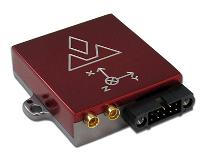
Red Bull Air Race has selected the VectorNav VN-300 dual-antenna GNSS-aided inertial navigation system (INS) as its primary source of aircraft telemetry data for Master Class raceplanes participating in the Red Bull Air Race World Championship.
Weighing less than 30 grams, the VectorNav VN-300 is a tiny dual-antenna GNSS-aided INS. It is used in applications ranging from autonomous vehicles to antenna pointing for satellite communication and aerial surveillance applications.
The inaugural event of the 2018 season in Abu Dhabi saw the VN-300, manufactured by VectorNav Technologies, used for the first time in all 14 aircraft to provide real-time telemetry data used for judging, in-race simulation and virtual reality applications.
Created in 2003, the world championship has held more than 80 races around the globe. The motorsport competition combines speed, precision and skill.
U.S. pilot Michael Goulian performs during the finals at the first round of the Red Bull Air Race World Championship in Abu Dhabi on Feb. 3.(Photo: Andreas Langreiter, Red Bull Content Pool)
Using the fastest, most agile, lightweight racing planes, pilots hit speeds of 370 km/h while enduring forces of up to 10 G as they navigate a low-level slalom track marked by 25-meter-high, air-filled pylons. Pilots incur time penalties for hitting pylons, incorrectly passing through air gates or only exceeding 10 G for more than 0.6 seconds, among others.
Being an individual sport, spectators need a reference to see the difference between the pilots’ lines and speed through the racetrack. Red Bull Air Race Live TV uses an augmented reality (AR) solution known as the Ghost Plane to display the trajectory of the pilots’ runs for real-time comparison in the head-to-head rounds and the Final 4 that decides the winner of the race by time.
The Ghost Plane is driven by the position, velocity and attitude data gathered during flight from the onboard INS.
Critical to the success of the Ghost Plane is the accuracy of the telemetry data, which, given the high dynamics experienced during flight, is extremely difficult to obtain.
For example, as a plane races through a chicane and into a vertical turn maneuver, GPS signals are lost and the INS needs to rely solely on the inertial sensors to accurately estimate the position and velocity until GPS is fixed again in level flight.
The VectorNav VN-300. (Photo: VectorNav)
“We evaluated several different inertial navigation systems and struggled to find one that was able to perform in our dynamics,” said Alvaro Navas, sport technical manager for the Red Bull Air Race. “VectorNav’s VN-300 was the only product able to deliver the attitude, position and velocity data accuracy we require, and it did this out of the box, no customization was required. The sensor is really amazing.”
“We are really excited to be working with Red Bull Air Race,” said Gordon Hain, VectorNav product manager. “Not only are we able to provide accurate data for the race judges and spectators, but we are also able to provide valuable information to pilots and tacticians. With the VectorNav data in hand, they are able to compare actual flight trajectories with their simulations to find areas for improvement. We are looking forward to continued work with Red Bull Air Race in the 2018 season and beyond.”
Spatial analytics company Esri has acquired technology from ClearTerra, a company that offers geospatial and activity-based intelligence tools.
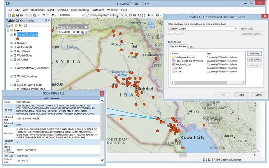
The acquisition will provide ArcGIS platform users the ability to easily discover and extract geographic coordinates from unstructured textual data like emails, briefings and reports, instantly generating intelligent map-based information.
This capability will make mapping this elusive information easier across many industries. Defense, intelligence and public safety organizations tend to have massive volumes of unstructured data, as do other fields, such as petroleum, utilities and maritime, where locating information on the Earth is not as easy as searching for a street address.
Esri’s acquisition of ClearTerra technology brings workflow-enhancing software technologies into the ArcGIS platform.
“We have been close partners with Esri for a number of years,” said Jeff Wilson, former vice president of sales for ClearTerra, now an executive for defense and intelligence with Esri. “Esri has the platform and resources to provide a solid path going forward for our technology, allowing us to expand this capability to the global market.”
ClearTerra LocateXT technology allows analysts to rapidly scan through documents without having to spend hours reading, copying, pasting and running spreadsheet formulas, placing the results instantly into geospatial features.
Additionally, ClearTerra FindFZ technology provides enhanced search capabilities for the ArcGIS platform, incorporating the powerful techniques found in internet search engines, including a tolerance for misspelled words, as well as wildcard and Boolean logic searches.
The LocateXT extension for ArcMap is used to extract locations from unstructured data (messages, reports, briefings) into a geodatabase feature class. (Image: ClearTerra)
“We are excited to bring ClearTerra technology into the Esri family,” said Jeff Peters, Esri director of national government. “The unstructured data tools are powerful not only for those who have made use of this technology for a number of years, such as in the military, but it also has useful applications for so many more Esri users.”
ClearTerra has been an active member of the Esri partner program, providing their software to ArcGIS users via desktop, server, and the cloud. Support and maintenance for the software will continue via Esri with no interruption of service, and is readily available for licensing.
ClearTerra specializes in geospatial and activity based intelligence software products, custom solutions, technical services, consulting and training. ClearTerra is a business unit of ClearShark.
u‑blox has rolled out the u-blox F9 technology platform, which was designed to deliver high-precision positioning solutions for mass market industrial and automotive applications.
The platform combines multi-band GNSS technology with dead-reckoning, high-precision algorithms, and compatibility with a variety of GNSS correction data services, to achieve precision down to the centimeter level.
u‑blox F9 paves the way for the next generation of high precision navigation, augmented reality, and unmanned vehicles, the company said.
The u-blox F9 platform will underpin the next wave of u‑blox positioning modules targeting mass market industrial and automotive applications. It uses GNSS signals in multiple frequency bands (L1/L2/L5) to correct positioning errors caused by the ionosphere and deliver fast time to first fix (Fast TTFF).
Its ability to receive signals from all GNSS constellations (GPS, GLONASS, Galileo, Beidou) further improves performance by increasing the number of satellites visible at any given time. Stand-alone u‑blox F9 solutions robustly achieve meter-level accuracy.
To achieve centimeter-level accuracy, u‑blox F9 offers optional on-chip real-time knematic (RTK) technology. In addition to offering an open interface to legacy GNSS correction service providers, it supports the main GNSS correction services, bringing RTK high-precision positioning to the mass market.
“High precision is the next frontier in positioning for mass markets, with countless applications in need of a robust and scalable high precision positioning solution. u‑blox F9 provides the hardware and integrated software components to address these needs,” said Daniel Ammann, executive director of positioning product development at u-blox.
Optimized for low power consumption, the u‑blox F9 platform sets a high standard for security with built-in jamming and spoofing detection systems that protect against intentional and unintentional interference. Dead-reckoning technology based on inertial sensors extends high-precision performance to otherwise challenging urban environments.
Automotive applications of the technology include lane-level navigation for head-up displays and vehicular infotainment systems as well as for vehicle-to-everything (V2X) communication, a prerequisite for highly automated and fully autonomous vehicles.
In the industrial realm, u‑blox F9 will enable mass adoption of commercial unmanned vehicle applications including drones and ground vehicles such as heavy trucks or robotic lawnmowers.
The u‑blox F9 platform’s technology will be showcased at Embedded World in Nuremberg, Germany from Feb. 27-March 1 at Booth #3-139. Product samples will be available later in the year.
The military is always looking at new techniques and technology for deriving position and, it seems, every few years signals of opportunity (SOOP) becomes fashionable again.
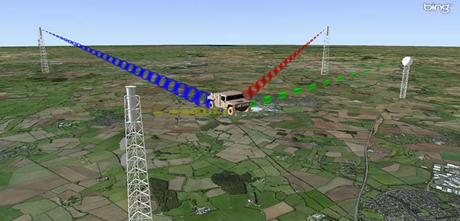
In broad terms, SOOP refers to the use of any signals for navigation, which are not normally intended for navigation. This might mean TV or radio broadcast signals, cellular network signals, or anything else you can receive.
Figure 1. Navigating using opportunistic signals, such as phone, TV and radio transmissions. (Image: Michael Jones)
The promise of SOOP
In the quest for resilient positioning and navigation, SOOP certainly sounds attractive. When GPS goes down, why not simply continue to navigate by receiving digital TV signals instead? Why not receive a whole pile of different signals, and make yourself virtually immune to jamming?
You can even turn jamming from a problem to a solution. If someone does decide to turn on a bunch of jammers, why not use the jammers themselves as signals of opportunity, and position yourself using those? With so many possibilities, it’s no wonder SOOP excites people. Certainly it’s of great interest to the military of many countries.
Let’s dip our toes into the world of opportunistic navigation.
What signals might we use?
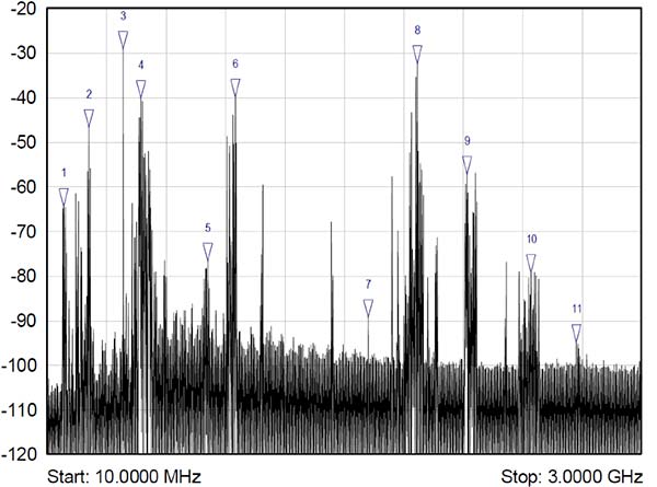
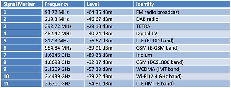
The figure below shows what we get if you use a spectrum analyzer to quickly sample what’s on the airwaves in the UK, in this case looking fairly coarsely from 10 MHz to 3 GHz. A number of candidate signals immediately present themselves, which are labeled 1 to 11 and identified in the table.
Figure 2. Plenty of opportunistic signals are out there. (Image: Michael Jones)
There are, of course, many more signals-of-opportunity out there, but this illustrates a few of the more visible ones. How do we go about using these signals for positioning ourselves?
Bringing in defense techniques
For decades, one of the principle requirements in electronic warfare (EW) has been to geolocate enemy transmissions. This has given rise to a plethora of techniques for determining location, such as received signal strength (RSS), angle-of-arrival (AOA), time-of-arrival (TOA), time difference of arrival (TDOA), frequency difference of arrival (FDOA), and so on.
In a positioning application, we have the reciprocal problem: instead of trying to geolocate a transmitter relative to ourselves, we are trying to geolocate ourselves relative to a set of transmitters. But of course we use the same techniques: GPS is an excellent example of a TOA system.
Let’s look at the basics of TDOA. A signal s arriving at location 1 can be expressed as
where A1 is an amplitude scaling to account for attenuation over the path, n1 is additional noise, and d1 is the signal delay time. We can repeat the equation for further locations:
Usually we designate one location as the reference, in which case we can rewrite the above equations as:
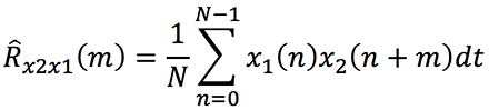
The first problem is to determine D, the time difference of arrival. There are many ways to do this, but a popular method is to perform generalized cross-correlation:
Or, in a realizable digital form:
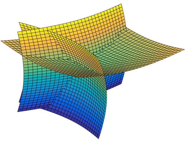
Finding the peak of this function gives us our estimate of the time difference D. It’s a little bit more involved in practice, as we would normally apply filtering functions to improve the TDOA resolution, but you get the idea. Each TDOA measurement gives a set of possible locations that form a hyperboloid. With three stations, we will have two hyperboloids, the intersection of which gives a set of possible locations along a hyperbola. The addition of a fourth signal allows us to plot three hyperboloids, from which we can then determine position.
Figure 3. Positioning using TDOA involves solving for the intersection of hyperboloids. (Image: Michael Jones)
There are various ways to solve for the hyperbolic intersections. With only four measurements it is possible to compute the solution analytically, but with many measurements an iterative approach or minimum mean squared error technique is often used.
TDOA, when used properly, can form the basis of a highly accurate positioning system. A number of navigation systems utilize TDOA technology, such as LORAN and its variants.
Now let’s consider angle-of-arrival. AOA techniques generally make use of an antenna array to provide spatial diversity, allowing the direction of a source transmission to be determined. Measured angles to multiple transmitters then allows triangulation to be performed and the position computed. There are some advantages to AOA techniques, when compared to TDOA: position can be computed with as few as three signals, there is no requirement for time synchronization in any form, and narrowband signals can be used without loss of accuracy. Disadvantages include larger physical size due to the use of an array of antennas, and potentially more susceptible to environmental effects such as multipath.
Classical AOA methods include Capon’s method, but since the 1980s the preferred techniques have often been signal subspace methods such as Multiple Signal Classification (MUSIC), Estimation of Signal Parameters by Rotational Invariance Techniques (ESPRIT), and variants of these techniques. The most well known of the subspace methods, MUSIC, performs an eigendecomposition of the sample covariance matrix given by:
Once the signal and noise eigenvectors have been separated the array manifold is projected into the appropriate subspace to yield the MUSIC surface:
The peaks of the function P, give us the direction-of-arrival of any signals. From these multiple lines of bearing we can perform triangulation, and derive our position.
We’ve looked at TDOA and AOA methods, which are just two of many techniques that can be used to process signals-of-opportunity to derive position. But there are some perceived drawbacks to navigation by SOOP. By definition, SOOP makes use of transmitters that are uncooperative, and not generally designed with navigation in mind.
For TDOA you are dependent on signals that are transmitted synchronously (or else you need a separate source of reference), which may or may not be the case. You also need to know the locations of the various transmitters, for example the coordinates of any GSM base stations, digital TV transmitters, and so on. It may be difficult to obtain this information, especially in some parts of the world. But whilst it certainly helps to have this information, it isn’t entirely necessary. It is possible to both position yourself, and build up a map of the transmitter locations, without a-priori information.
SLAM
Simultaneous localization and mapping (SLAM) is a field popular in the autonomous vehicle and robotics communities. It’s often described as a machine-learning concept, which aims to solve the problem of positioning oneself within a map, whilst simultaneously constructing and updating that map. There are a pile of techniques and algorithms that have been applied to the problem, including the good old Kalman filter, and the particle filter.
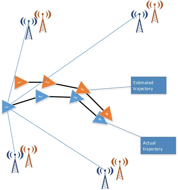
In basic SLAM, you use a state vector to store an estimate of your position (and often orientation as well), just as you would in a typical GPS receiver. However, in SLAM, we also store estimates of the transmitter positions (called “features” in SLAM terminology). If we want to localize ourselves in a global coordinate frame it does mean we need an initial estimate of our position from some other means, like GPS. Otherwise we can only localize ourselves within the map we are generating.
From our initial position estimate, we then move in some way. We then estimate our position again, perhaps using some form of dead reckoning technique, like inertial or visual odometry. Together with our motion model, this forms the prediction phase of the Kalman filter. We perform the measurement phase by re-measuring any features (our transmitters of opportunity), along with any new ones.
Figure 4. Basic SLAM concept: simultaneously estimate the locations of both the vehicle and the transmitters of opportunity. (Image: Michael Jones)
If you know about Kalman filters, you might spot one of the problems with SLAM: As the number of features increases, the size of the state vector becomes larger, until you end up with huge matrices that are very time-consuming to solve. The solution time is a quadratic function of the number of state variables. For this reason, it is often necessary to constrain the problem in some way: perhaps by limiting the number of transmitters we keep track of.
But when done properly, SLAM is a powerful technique for signals-of-opportunity navigation.
Is SOOP worth it?
We’ve seen that, by using a variety of techniques, almost any radio signal can be used for opportunistic navigation purposes.
One disadvantage of SOOP is that it can require complex hardware to do it well. If you truly want to use all the opportunistic signals out there, then you need a receiver that can handle a very wide range of frequencies. You also need an antenna or set of antennas that can do the same.
When resilient PNT is a critical military requirement, you cannot afford to rely on signals that you don’t control. SOOP is also highly dependent on where you are. There aren’t many opportunistic signals at sea or in the desert, compared to in the urban environment (perhaps the odd satellite signal, or HF signal).
So SOOP is unlikely to become a primary technology for the military. But it does have the potential to be a powerful augmentation to GNSS, and it certainly deserves a place in the PNT kit bag.
This comment piqued my ears when heard over the coffee-break table at ION’s International Technical Meeting last month: “There is a great deal of mutual ignorance between the 5G and PNT communities. I think that the 5G people are pretty naive about PNT and the PNT community is missing an opportunity.”
So when news releases leading up to next week’s Mobile World Congress — several of them mentioning 5G in rosy terms, “catalyst for a better future” typical among these — started flooding my inbox this morning, it seemed an opportune time to investigate. Pardon my top-slice view; I’m not well-versed enough in the technology to discourse knowledgeably, but here’s quick round-up of salient points related to positioning in the fast-oncoming Next Step in cellular communications.
Regular contributing editor for Professional OEM and UAV Tony Murfin will return to this space next month, with a column previewing the massive AUVSI Xponential show in Denver, April 30–May 3. He’ll be there, too, covering the event!
The cellular 5G standard has been designed to target latencies under one millisecond, data rates of up to ten gigabits per second, extremely high network reliability, and better accuracy in positioning. With location awareness becoming an essential feature of many new markets, positioning is consequently considered as an integral part of the system design of upcoming 5G mobile networks.
Its feet firmly planted in both the present and the future, the cellular industry is currently in the midst of implementation of Long Term Evolution (LTE)-Advanced, an evolution of what might be called plain old LTE, and a “true 4G” mobile broadband. Simultaneously, the industry is preparing the next step, as “there is a vastly increased need for a new mobile communications system with even further enhanced capabilities, namely a fifth generation (5G) system.” 5G will process communication 10 times faster than 4G, according to experts. That’s enough to download a 3D movie in 30 seconds. It would take six minutes on 4G.
Pyeongchang
Alert techie viewers of the present ongoing Olympics in South Korea may have noted 5G in action there, in demos of such things as live-streaming virtual reality of bobsled and luge runs, putting the viewer in the breathtaking driver’s seat, and a test drive earlier this month from Seoul to Pyeongchang, a journey of several hours, without any human intervention whatsoever at the car’s controls. The demonstrations in Pyeongchang are laying down a backbone for what will be on show at the Tokyo Games in 2020, when 5G roll-out will be complete in many major metro areas.
As trumpets sound the fanfare for next week’s Mobile World Congress in Barcelona, AT&T announced it will first roll out 5G to three locations: Dallas, Texas; Waco, Texas; and Atlanta, Georgia. The plans introduce the service to about a dozen U.S. markets by late this year. Qualcomm meanwhile is offering insight into its 5G chips.
What has all this got to do with GNSS? Well, aside from the aforementioned precise positioning via cellular to be afforded by 5G, the two technologies share one prominent technique: adaptive array antennas for digital beam-forming. Here I am indebted to Gary McGraw of Rockwell Collins for a primer on the subject, which he presented at the International Technical Symposium on Navigation and Timing (ITSNT) in November 2016.
Adaptive array technologies have many advantages for PNT: primarily, in mitigation for multipath and for jamming and spoofing mitigation. Adaptive antenna arrays with digital beam-forming (DBF) are becoming increasingly important for PNT in challenging signal environments. DBF combines multiple antenna inputs to generate gain in arrival direction of the desired satellite signal and to create spatial nulls in direction of jamming.
Emerging applications of DBF in 5G involve dense networks of picocells, small cellular base stations typically covering a small indoor area. Picocells extend coverage where outdoor signals do not reach well, and add network capacity in areas with very dense phone usage. In this context, 5G cellular architectures will use adaptive array technology to achieve high data rates, spectrum reuse and communications robustness.
The implications for PNT are that 5G system architectures will require improved (relative) PNT to operate effectively, and these 5G picocells will be a source of PNT information in constrained environments.
5G involves massive directional communications via multiple-input multiple-output (MIMO), enabling high-bandwidth communications in fading (multipath) channels by using multiple antenna inputs to adapt to channel. It can do this without knowledge of user location, but it adds to the processing complexity. The directional capability can enable multiple users to be serviced in a picocell at different frequencies, while permitting spectrum re-use by nearby picocells through narrow beam-width and the limited range of millimeter-wave frequencies.
The PNT implications of 5G architectures, according to Gary McGraw of Rockwell, are, principally, that efficient operation of directional links will require some level of knowledge of user location with regard to picocells. Picocells will need to have the ability to do direction-of-arrival positioning and ranging in order to maintain connectivity with user nodes. This can be exploited by the user node for positioning and location-based services, particularly for indoor and dense urban environments. Meanwhile, the proliferation of adaptive array technology will drive down costs for other applications. Further, millimeter-wave transmit/receive modules will become commodity items, analogous to what cell phones have done for GPS chips.
McGraw’s Summary
5G picocells will be synergistic with PNT in challenged environments — naturally, indoor and dense urban. They will necessitate development of distributed, networked PNT processing and infrastructure. Availability of adaptive array technology will increase with deployment of 5G, and costs can be expected to drop dramatically. In addition to GNSS, adaptive array technologies can be employed to support short-range, relative PNT applications such as vehicle-to-vehicle communications and relative positioning.
Driving the Bus
The key driver for all this is that customers, the global We, expect the same quality of experience from Internet applications anytime, anywhere, and through any means of connectivity. The rapid proliferation of smartphones and other mobile devices that support a wide range of applications and services mean that image transfer and video-streaming, as well as more cloud-based services, such as cloud speech services, have become the new norm. Their requirement for massively more data than, say, simple texting is conveniently hidden from or forgotten by users. We want it. We want it now.
From a DOCOMO 5G White Paper: 5G Radio Access: Requirements, Concept and Technologies. NTT DOCOMO, INC., July 2014. At https://www.nttdocomo.co.jp/english/binary/pdf/corporate/technology/whitepaper_5g/DOCOMO_5G_White_Paper.pdf.
Tomorrow, or perhaps the next day, everything will be connected by wireless to enable monitoring and collection of information and control of devices. Thus, remote monitoring and real-time control of nearly all electronic devices in machine-to-machine (M2M) services and Internet of things (IoT): connected cars, connected homes, moving robots and sensors. Such services will become more extensive and enriched through richer content delivered in real-time. Get set for the tactile Internet, augmented reality, and other brave new wonders.
Fraunhofer Enters the Fray
The 5G positioning framework will thereby integrate a multitude of sensors based on both, cellular signals and 3GPP independent techniques, into a hybrid positioning scheme, according to the Fraunhofer Institute for Integrated Circuits (IIS) in Germany. Fraunhofer IIS is currently prototyping low-latency and high-precision positioning systems for legacy LTE and future 5G New Radio (NR). Two selected industrial IoT live demonstrations can be seen at next week’s Mobile World Congress 2018.
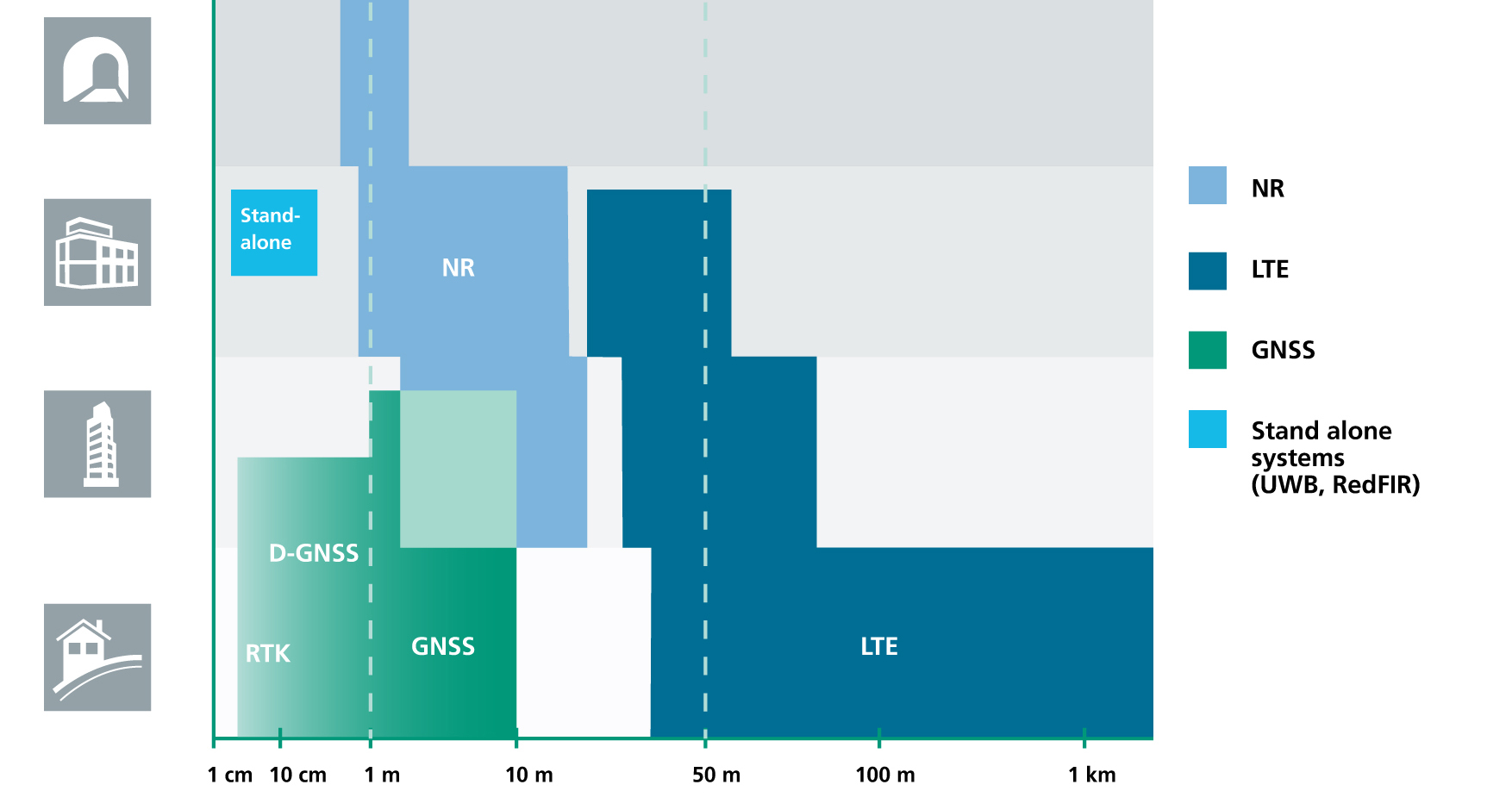
Respective positioning performance for 5G NR and other technologies in different environments. (Image: Fraunhofer IIS)
5G NR enables positioning performance by providing high bandwidths for precise timing, new frequency bands at mm-wave, massive MIMO for accurate angle-of-arrival estimation and new architectural options that support positioning. Improved levels of accuracy, robustness and latency, not possible today, can soon be achieved, according to Institute. 5G provides fast and reliable access to moving objects, to achieve time-critical process control and optimization in industrial environments not possible with today’s cellular technology. As requirements vary according to the specific use cases, 5G NR will provide a flexible air interface allowing for scalable bandwidths, data rates, latencies, and positioning accuracy levels.
High-Precision Positioning
With location awareness becoming an essential feature of many new markets, positioning is an integral part of the system design of 5G mobile networks. Increased contextual awareness of goods, parts, machines and workers will enable new interaction and collaboration.
High-precision positioning, in the view of Fraunhofer IIS. (Image: Fraunhofer IIS)
Fraunhofer IIS is working on novel approaches for sub-meter accuracy to enable tracking of mobile devices in indoor and urban areas where GNSS is not sufficiently accurate nor available. Its 5G positioning framework integrate several sensors. The key benefits of 5G in this regard are high accuracy, reliability, mobility and coverage; low latency and low power; and scalability.
The Institute offers the facilities of its Test and Application Center L.I.N.K. in Nuremberg, Germany. The test center includes a 3D positioning system capable, according to the organization, of reproducing, simulating and emulating all kinds of possible environments, using every common communication and positioning system commercially available.
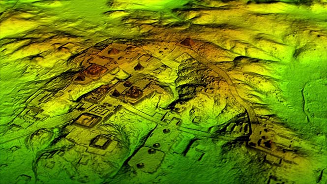
Lidar and UAV technology has revealed hundreds of previously unknown Mayan ruins in the Guatemalan rainforest.
The Optech Titan stripped away overlying vegetation to reveal extensive Mayan ruins in Guatemala’s rainforest. (Image: Teledyne Optech)
In what is considered biggest aerial lidar survey in the history of archaeology, a vast and complex civilization has been discovered.
The University of Houston’s National Center for Airborne Laser Mapping (NCALM) used Teledyne Optech’s Titan sensor to identify raised highways, and complex irrigation and terracing systems.
The jungle of Central America is one of the last great frontiers of archaeology, according to National Geographic, which covered the new finds in a recent documentary, Lost Treasures of The Maya Snake Kings.
After the collapse of the Mayan civilization, its cities and monuments were quickly covered by thick rainforest, hiding it from airborne observation and making it very difficult to survey on foot. Over decades of work, the ancient civilization has gradually been revealed. But now technology is set to change everything.
Lidar digitally removes the forest canopy to reveal ancient ruins below, showing that Maya cities such as Tikal were much larger than ground-based research had suggested. (Photo: National Geographic)
Flying high above the rainforest, the Titan’s lasers penetrated the canopy to collect almost a million data points per second from the forest floor, giving archaeologists a “bare earth” view of the structures underneath.
Having covered 2,100 square kilometers, the Titan’s data revealed massive amounts of ruins hidden below the forest, showing that their urban centers were significantly larger than archaeologists had previously thought.
“Lidar is revolutionising archaeology the way the Hubble Space Telescope revolutionised astronomy,” Francisco Estrada-Belli, a Tulane University archaeologist, told National Geographic. “We’ll need 100 years to go through all [the data] and really understand what we’re seeing.”
(Image: Teledyne Optech)
“We are incredibly proud and excited that our award winning Titan multispectral lidar sensor has contributed to this spectacular discovery,” said Michel Stanier, EVP and general manager of Teledyne Optech. “The Titan’s ability to strip away overlying vegetation and map wide areas very quickly and accurately makes it an important tool for archaeologists, and we expect to see many more discoveries coming from it and our other airborne laser terrain mappers.”
The Optech Titan multi-spectral lidar sensor incorporates three independent laser wavelengths into a single sensor design, with beams at 532, 1064 and 1550 nanometers (0.5/1.0/1.5 microns) and a ground sampling rate of 300 kHz per beam.
Because Titan uses both green and infrared channels, it is capable of simultaneous water-depth mapping and high-precision 900-kHz topography.
Titan can also be used for purposes such as vegetative and forestry applications, which require multiple wavelengths for improved classification accuracy and carbon credit counting initiatives.
Lidar and UAV technology has revealed hundreds of previously unknown Mayan ruins in the Guatemalan rainforest.
The Optech Titan stripped away overlying vegetation to reveal extensive Mayan ruins in Guatemala’s rainforest. (Image: Teledyne Optech)
In what is considered biggest aerial lidar survey in the history of archaeology, a vast and complex civilization has been discovered.
The University of Houston’s National Center for Airborne Laser Mapping (NCALM) used Teledyne Optech’s Titan sensor to identify raised highways, and complex irrigation and terracing systems.
The jungle of Central America is one of the last great frontiers of archaeology, according to National Geographic, which covered the new finds in a recent documentary, Lost Treasures of The Maya Snake Kings.
After the collapse of the Mayan civilization, its cities and monuments were quickly covered by thick rainforest, hiding it from airborne observation and making it very difficult to survey on foot. Over decades of work, the ancient civilization has gradually been revealed. But now technology is set to change everything.
Lidar digitally removes the forest canopy to reveal ancient ruins below, showing that Maya cities such as Tikal were much larger than ground-based research had suggested. (Photo: National Geographic)
Flying high above the rainforest, the Titan’s lasers penetrated the canopy to collect almost a million data points per second from the forest floor, giving archaeologists a “bare earth” view of the structures underneath.
Having covered 2,100 square kilometers, the Titan’s data revealed massive amounts of ruins hidden below the forest, showing that their urban centers were significantly larger than archaeologists had previously thought.
“Lidar is revolutionising archaeology the way the Hubble Space Telescope revolutionised astronomy,” Francisco Estrada-Belli, a Tulane University archaeologist, told National Geographic. “We’ll need 100 years to go through all [the data] and really understand what we’re seeing.”
(Image: Teledyne Optech)
“We are incredibly proud and excited that our award winning Titan multispectral lidar sensor has contributed to this spectacular discovery,” said Michel Stanier, EVP and general manager of Teledyne Optech. “The Titan’s ability to strip away overlying vegetation and map wide areas very quickly and accurately makes it an important tool for archaeologists, and we expect to see many more discoveries coming from it and our other airborne laser terrain mappers.”
The Optech Titan multi-spectral lidar sensor incorporates three independent laser wavelengths into a single sensor design, with beams at 532, 1064 and 1550 nanometers (0.5/1.0/1.5 microns) and a ground sampling rate of 300 kHz per beam.
Image: Teledyne Optech
Because Titan uses both green and infrared channels, it is capable of simultaneous water-depth mapping and high-precision 900-kHz topography.
Titan can also be used for purposes such as vegetative and forestry applications, which require multiple wavelengths for improved classification accuracy and carbon credit counting initiatives.
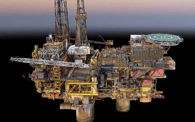
As part of a framework agreement with Dubai Petroleum, Cyberhawk was appointed to inspect more than 350 risers on 63 offshore platforms. The inspection took one month to complete, followed by the production of more than 90 detailed engineering inspection reports.
Photo: Cyberhawk
The rationale behind Dubai Petroleum’s use of UAVs was to quickly complete detailed inspections of all their risers. Risers are traditionally a difficult area of an offshore platform to inspect; in the under deck and the splash zone, options for access, such as abseiling or scaffolding, are limited, extremely time consuming and very expensive.
Using UAVs as a scanning tool, the high-quality reports produced by the Cyberhawk team allowed the client to plan contact-based inspections or repairs. With a full inspection completed on all risers, defects can be tracked over time to understand their long-term degradation.
Daily reports were produced to notify Dubai Petroleum of potentially serious defects, with detailed inspection reports then produced by Cyberhawk’s experienced oil and gas inspection team.
On the same project, an additional three elevated flare stacks and 24 bridges were inspected, maximizing the value of the mobilization.
Image: Cyberhawk
“Having worked with Cyberhawk in the past, we understand and appreciate the potential on offer from UAV inspections,” said Dubai Petroleum’s asset integrity manager. “This confidence led us to use UAVs in a new area within our business; this risers survey project. The campaign was a great success and we are pleased with the outcome. The speed and efficiency with which this project was completed has proven that the scope and application of UAV inspection can be expanded for our requirements, and we look forward to continuing our relationship with Cyberhawk in the future.”
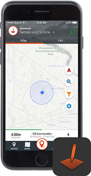
The application, built using the TerraGo Magic platform and available today from BAE Systems, offers iOS, Android and web apps that make it easy to securely capture and share field reports from any location.
With GXP InForm, users can customize forms, maps and workflows so field applications can be quickly configured and instantly deployed to support any operation, in any location.
GXP InForm’s mobile features, including basemaps and forms, are available without network connectivity so personnel can get the job done in the most remote locations and demanding conditions. When a network connection is available, GXP InForm enhances situational awareness for all stakeholders with the bi-directional flow of information between headquarters and on-site personnel.
“We constantly look for ways to help our customers extend the value of GXP Xplorer across the enterprise and improve the quality of geospatial intelligence for all stakeholders,” said Damon Brady, director, product development and programs at BAE Systems. “With GXP InForm, mobile users get access to actionable imagery, while command units gain access to site reports, photos and videos that enhance the fidelity of their common operating picture.”
“We’re proud of this collaboration to build GXP InForm,” said Dave Basil, president and CEO at TerraGo. “It’s the result of a long-running and successful partnership with BAE Systems that goes back to 2008. The combination of GXP Xplorer, as an open data-management platform, and GXP InForm, as a customizable reporting application, provides great value to our customers that need to leverage vast geospatial data sources and tailor field workflows to all types of operations and missions.”
TerraGo is offering a webinar at 1 p.m. ET on Feb. 21, with a discussion and demonstration of GXP InForm. Register here.
Helix Technologies Ltd. has been awarded a significant contract by the European Space Agency (ESA) to develop its next-generation GNSS antenna — a multi-frequency antenna optimized for the advanced Galileo E1 Alt-BOC and wide-band E5 Alt-BOC waveforms for use in driverless cars.
The antenna, to be developed under the ESA’s Navigation Innovation and Support Programme (NAVISP), will provide enhanced performance due to its dielectric, multi-filar construction. It will also be optimized to take maximum advantage of the Galileo E5 Alt-BOC waveform, which enables significantly improved measurement accuracy, precision and multipath suppression over conventional GNSS signals.
Learn more about the Helix Technologies antenna in our February issue article here.
“In order to achieve the 10-centimeter accuracy that is required for autonomous vehicle lane-level positioning within challenging urban multi-path propagation conditions, there is a need both for a significant improvement in current GNSS antenna performance and to fully exploit the advanced Alt-BOC waveforms transmitted by Galileo,” said John Yates, managing director of Helix Technologies.
The GNSS antenna, which will also be capable of optimized operation with the GPS L1 and L5 M BOC signals, is aimed at the automotive and consumer markets, and the company is targeting the third quarter of this year for the manufacture of prototypes.
Independent testing and evaluation of the vehicle-mounted antenna performance will be conducted in the challenging multipath environments of the high-rise financial districts of the cities of London and Shanghai.
The contract will be awarded to a single bidder, the Air Force Space Command stated in the announcement posted on FedBizOpps.gov. The estimated dollar value of the acquisition is $10 billion including all options.
Phase 2 is planned as a single, predominantly fixed-price incentive-type contract awarded via full and open competition for production of 22 GPS III satellites. Deadline for proposals is April 16. Construction is to begin in fiscal year 2019 (Oct. 1, 2018), with delivery of the first satellite in 2026.
For Phase 1, AFSC awarded in May 2016 three fixed-price contracts to Boeing Network and Space Systems, Northrop Grumman Aerospace Systems and Lockheed Martin Space Systems Company, which is building the first 10 GPS III satellites. According to the Air Force, “Phase 1 has determined that viable, low-risk, high-confidence sources exist to conduct a full and open competition for Phase 2, the production of 22 GPS III SVs starting in the FY19 timeframe.”