Now the company has released from new tests using configurations with a differential source and with a more accurate OCXO clock, producing timing accuracy of 160 nanoseconds.
Gregory Gutt, president and chief technical officer of Satelles, made the presentation at the recent Institute of Navigation International Technical Meeting.
The 66-satellite Iridium LEO constellation transmits overlapping spot beams, which provide location-specific data that changes every few seconds. The featured image on this article (above) shows spot beam pattern for 2 of 66 satellites.
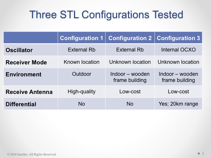
Overview of Satelles test configurations. (Chart: Satelles)
The testing employed three different configurations of equipment, services, and environment, as shown in the adjacent figure. Equipment employed in the tests included a Stanford Research Systems (SRS) rubidium vapor frequency reference, based on the PRS10 module, and a Satelles Evaluation Kit (EVK2) STL receiver, comprising a Maxim RF chip, Xylinx Spartan-3 FPGA , TI dual core DSP chip, and internal OCXO or external clock.
Parameters and equipment for the three test configurations:
Configuration #1 – Optimal. Outdoor antenna, Rubidium clock powered on for months prior to data collection, receiver configured in static mode with a known location, and high-quality antenna
Configuration #2 – Sub-optimal. Indoor antenna, Rubidium clock powered on 6 hours prior to data collection, receiver configured in static mode with an unknown location, and low quality antenna
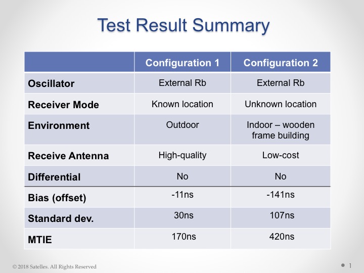
Results from the first two tests are shown here:
Test results, configurations 1 and 2. (Chart: Satelles)
Configuration #3. Three independent receivers collecting data, receiver on-board OCXO, indoor antenna, receiver configured in static mode with an unknown location, low-quality antenna. Tests performed:
10 days with no local reference station running
10 days with local reference station, 20km away from test receivers, providing timing corrections to STL ground segment.
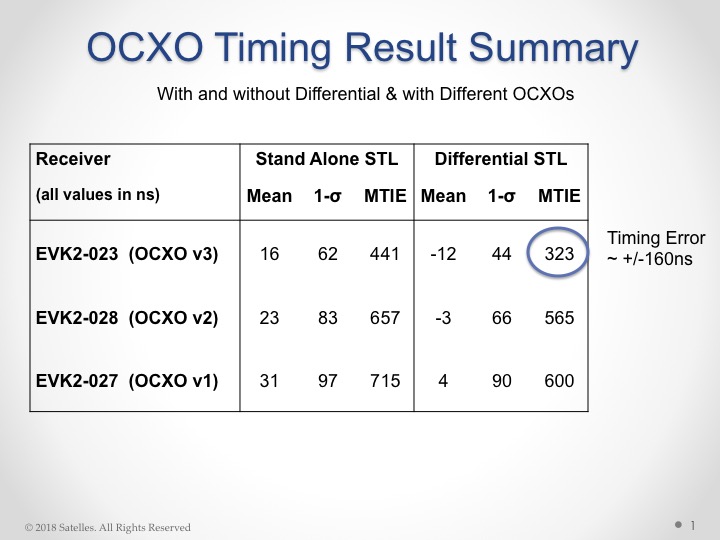
Results from these tests shown here:
Results from OCXO tests. (Table: Satelles)
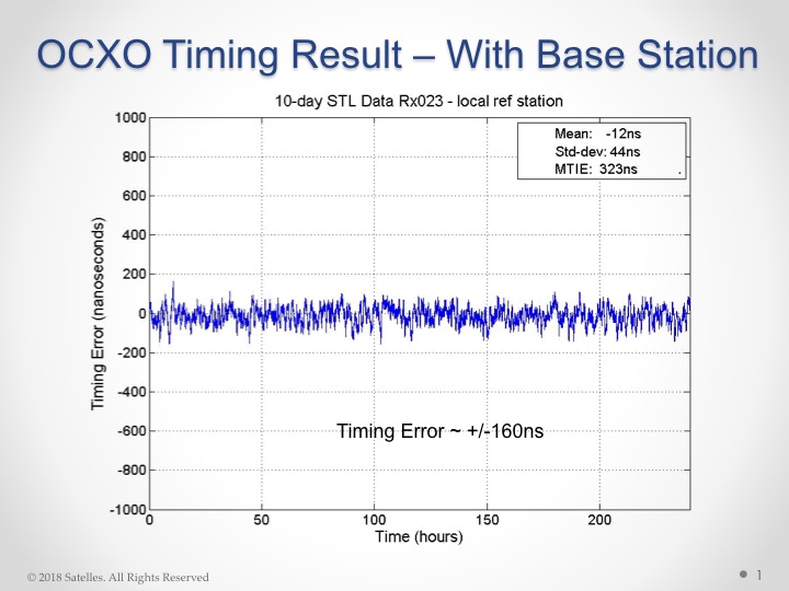
With this individual test result:
OCXO timing result with base station. (Chart: Satelles)
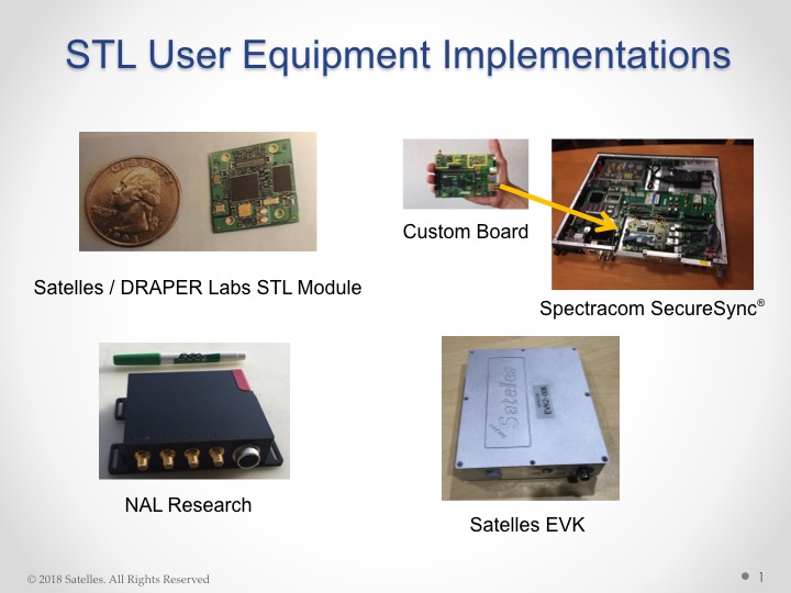
Some of the commercially available products and evaluation kits that incorporate the STL service are shown here:
STL user equipment implementations. (Image: Satelles)
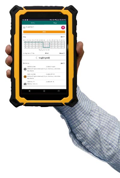
FleetUp Trace is a ruggedized tablet designed for fleet drivers required to display Records of Duty Status (RODS) upon request instead of printing out hard copies with the new Electronic Logging Device (ELD) mandate. Tim provides thoughts on the product hardware, ease-of-use and various app features.
Photo: FleetUp-Trace
By Tim Spence
Sometimes, there is great anticipation when buying a new electronic gadget. The look, the feel and the flashy presentation is what many products on the market rely on to make their product the best. With ELDs though, drivers and fleets managers are thinking about these products a bit differently. Thoughts like:
Will this satisfy our need for compliance?
How much training will this take?
How many drivers am I going to lose?
Is this even going to work?
When powering up the FleetUp Trace tablet for the first time and opening the Hours of Service (HOS) app, it was evident that a lot of thought went into fulfilling these needs. Here is a first look at FleetUp Trace, a ruggedized tablet designed for fleet drivers required to display Records of Duty Status (RODS), as part of the FMCSA ELD mandate.
Unboxing
When removing the FleetUp Trace case from the box, you will notice that it is quite unique and will not easily be lost among other items because of that. The case was durable and tough but soft as well. When unzipped it revealed the Android tablet, a couple of short manuals and various accessories for charging and memory.
The Tablet
Safety orange is the key color with this tablet and since it is a popular color in our industry, it definitely catches the eye. In addition, the protective case fits the tablet so well, it looks to be a part of the product (if you have ever purchased a tablet and tried to find a durable hard case that fits well, you know).
Booting the tablet, a brilliant orange screen for FleetUp appears and then four preloaded apps on the home screen: FleetUp’s HOS app, FleetUp’s CamVue app, Camscanner (a very reliable document scanner) and a preset version of Teamviewer QuickSupport, which provides an ID and easy instructions to show the FleetUp screen to another device.
HOS app tutorial
Starting the app and logging in, the Voice Over HOS greets you by name, gives you the current date, tells your current duty status, how many hours you have left in the 70-hour cycle, and how many on-duty hours you have before you are required to take a break. It then tells you to select a vehicle. After selecting a vehicle and confirming, you are told to tap the HOS button.
The app automatically uses a tutorial showing each feature. One button at a time, the app guides you to the next feature prompted by your action of pressing the “GOT IT” button. This tutorial is available on each section of the device and can be turned off on the main menu that slides over from the left. That is a great feature not only because you wouldn’t want to go through the tutorial EVERY SINGLE TIME but just in case you forget how to use a certain section, like driver vehicle inspection report (DVIR), you can manually slide open the main menu and turn it back on to REINFORCE YOUR LEARNING. After going through the tutorial for each section, you will find a lot of reasons (mainly regulatory) why this is valuable.
Using the HOS app
After going through the tutorial once, even if you have years of experience on paper logs, you will find that many of the basics of logging are easy to find or figure out. It is very comfortable operating without the Voice Over HOS or Tutorial features. On the “Status” tab, you can see your current status and log graph, as well as change your status and check your available hours. On the “LOGS” tab, you can fill out a pre-trip or post-trip inspection and edit your time (except for driving time, of course). This section also allows you to enter shipping document information, edit any equipment information and certify your logs by signing with your finger (no special pen needed).
Features that make the difference
Tutorial mode. While this feature may sound simplistic, it has the capability to answer a driver’s question with the flip of a switch. Just the fact that you can turn it on whenever you need to be reminded is so valuable. It is beneficial to know that this feature does work best in the portrait or vertical mode.
Voice over HOS. This feature reminds you of the actions that many drivers forget. If you have ever used ELDs in the past as a driver or fleet manager, you understand. Along with the text prompts, it reminds the driver to do things such as certifying the log at the end of the day, sign the DVIR, release the vehicle, etc. All the voice and text prompts work hard to keep the driver in compliance. Even when you want to LOG OUT, the app asks you if you still need to complete unfinished actions.
Easy-to-read availability. Many electronic logging devices make it very challenging to understand what hours are left for a driver. With FleetUp, there is no confusion at all because it is stated in text and graph.
Big buttons to change status. No more calibrating screens or needing a stylus just to change your status. Just touch a big button with your finger, enter the note under the GPS-enabled address entry, and tap “Yes.” It is that easy.
On top of everything else, FleetUp Trace and the HOS app are extremely user-friendly. This should be the key to it all because if the device and app are not user-friendly and easy to operate, there is no reason for it to exist.
FleetUp has accomplished a great feat by making the transition to E-Logs painless and smooth while complying with a multitude of regulations. Whether you’re looking for a simple way to track internal records of duty status (RODS) or to ensure HOS compliance and DVIR with a simple, hands-free gadget, FleetUp is one provider that clearly committed a lot of thought into what drivers are going to go through on the road, and offers plenty of features for an all-encompassing solution to the ELD mandate.
Tim Spence, creator of Apps4truckers, is an app consultant, writer and safety manager in Birmingham, Alabama.
Modules featuring Altair’s ALT1250 CAT-M1/NB1 chipset will be demonstrated at Mobile World Congress.
Altair Semiconductor, a provider of LTE chipsets, has selected Rohde & Schwarz as its partner for test equipment for its dual-mode CAT-M1/NB1 internet of things (IoT) ALT1250 chipset, as well as its next-generation IoT chipsets.
The ALT1250 is a highly integrated dual-mode CAT-M1/NB-IoT chipset with GNSS. Modules with ALT1250 inside are the world’s smallest, and may be as small as 100 millimeters square in area.
The ALT1250 includes GNSS location positioning, a wideband RF front-end supporting all commercial LTE bands within a single hardware design, a multi-layered and hardware-based security framework, an internal application subsystem and packaging that enables standard, low-cost PCB manufacturing.
The Rohde & Schwarz R&S CMW500 test platform offers the most validated CAT-M1/NB-IoT protocol conformance tests. It allows manufacturers and test houses to use a single instrument to verify that chipsets, modules and devices comply with GCF and PTCRB standards, and specific network operator requirements.
The test equipment will be used for protocol testing as well as RF, RRM performance and carrier tests.
Rohde & Schwarz is a global manufacturer of wireless communications and EMC test and measurement equipment and plans to develop new testing protocols for Altair’s next generations of cellular IoT chipsets.
“Our ALT1250 chipset is already forming the foundation for multiple current and emerging IoT applications,” said Ilan Reingold, VP of business development and marketing for Altair. “The choice of Rohde & Schwarz is part of our commitment to the highest quality of advanced validation and performance testing for our game-changing products.”
“This announcement confirms the commitment of Rohde & Schwarz to the wireless industry to provide innovative test tools and solutions that allow the testing and certification of cellular IoT devices,” said Anton Messmer, vice president, mobile radio testers, for Rohde & Schwarz. “We are pleased to have been selected by Altair and are looking forward to supporting them in the development of highly integrated chipsets in conformance with 3GPP Release-13 standards for CAT-M1 and NB-IoT, and beyond.”
Altair will be demonstrating partner modules based on ALT1250 at Mobile World Congress (MWC) in Barcelona, Spain, Feb. 26 to March 1 at Altair meeting rooms in Hall 2, Stands 2B2Ex and 2B4Ex.
Rohde & Schwarz will showcase CAT-M1/NB-IoT test solutions with the R&S CMW500 at MWC in hall 6, booth 6C40.
Two methods of spoofer detection, the identification and sourcing of false GNSS signals, have been released by Javad GNSS, using features available for all of its OEM GNSS boards.
Spoofer detection and alarm. This feature then identifies and isolates the spoofer signal, ignores it, and provides a position solution using only valid satellite signals.
Determination of the direction from which the spoofing signals emanate. This can aid in tracking down the actual spoofing source.
Spoofer Detection
With 864 channels and roughly 130,000 quick-acquisition correlators, the Javad GNSS Triumph chip can assign more than one channel to each GNSS satellite, in order to find all the signals that are transmitted with that satellite’s PRN code. If the chip detects more than one reasonable and consistent correlation peak for any PRN code, it concludes that spoofing is present and can the proceed to identify the spoofed signals.
In this case, it uses the position solution provided by all other clean signals (L1, L2, L5, and so on, from all GNSS constellations — GPS, GLONASS, Galileo, Beidou, and mroe) to identify the spoofer signal and use the real satellite measurement. If all GNSS signals are spoofed or jammed, then the system issues an alarm, directing the user to ignore GNSS and use other sensors in an integrated system.
Satellite and Spoofer Peaks
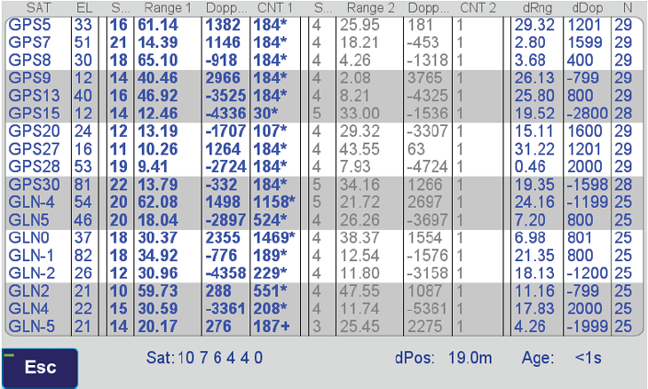
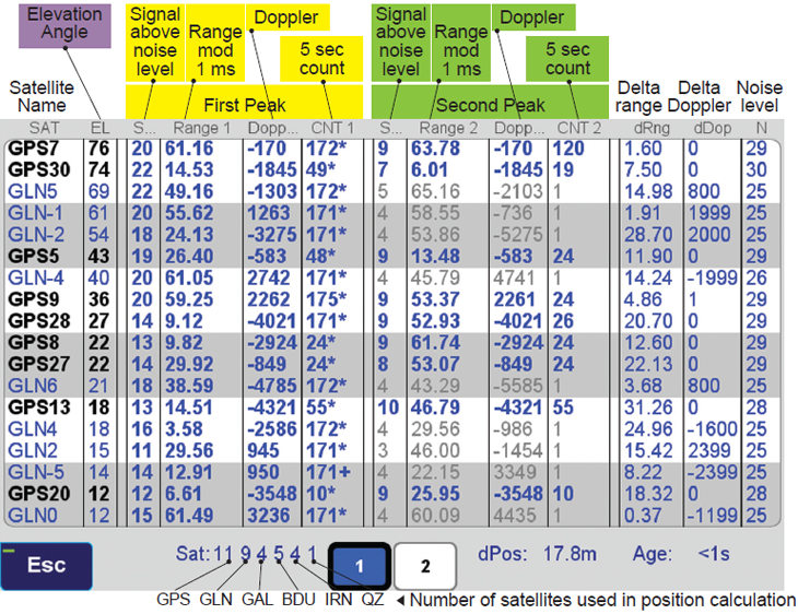
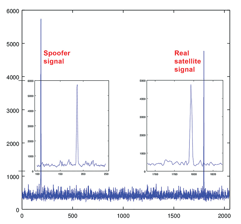
The figure below shows an example of a spoofer signal and a real satellite signal received at a GNSS receiver. These screenshots are from a real spoofer in a large city. The bold numbers are for the detected peaks. The gray numbers represent highest noise, not a consistent peak. A “*” symbol next to the CNT numbers indicate that signal is used in position calculation. Each CNT count represent about 5 seconds of continuous peak tracking.
The first screenshot shows no spoofing is present. The second shows that all GPS satellites are being spoofed.
No spoofer. Only one reasonable peak for each satellite. (Table: Javad GNSS)Table: Javad GNSS
In the above screenshot all GPS satellites have two peaks and all are spoofed. We were able to distinguish the spoofer signal and use the real satellite signals in correct position calculation as indicated by the ”*” next to the CNT numbers.
GNSS Overall View
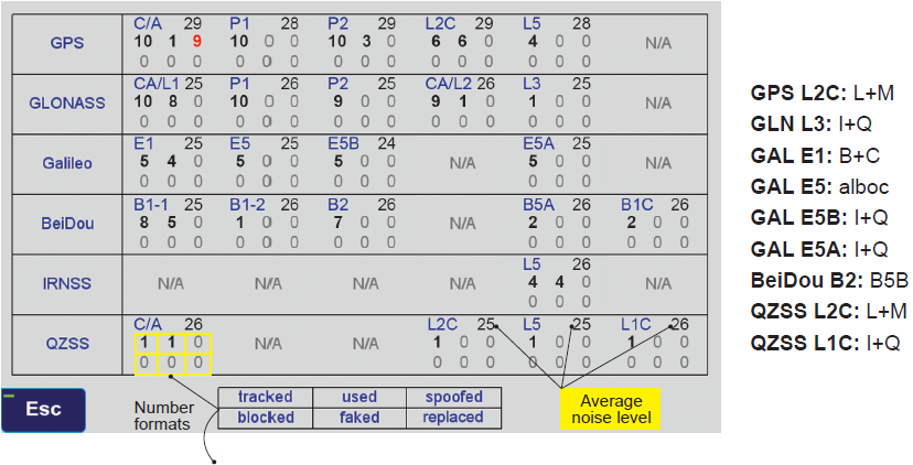
The following screenshot shows the status of all GNSS signals. The format and the signal definitions are explained below.
Table: Javad GNSS
Tracked: Tracked by the tracking channels and has one valid peak only.
Used: Used in position calculation.
Spoofed: Has two peaks. Good peak is isolated, if existed.
Blocked: Blocked by buildings or by jamming. If jammed, shows higher noise level.
Faked: Satellite should not be visible, or such PRN does not exist.
Replaced: Real signal is jammed and a spoofed signal put on top of it. Because of jammer, it shows higher noise level.
The U.S. Air Force plans to release a request for proposal (RFP) for the second phase of GPS III Follow-On satellite production “on or about” Feb. 13, according to a report by Inside Defense.
The RFP was expected in December 2017, but was held up as officials worked to solidify requirements.
The solicitation is expected to result in a contract for up to 22 GPS III Follow-On satellites in the 2019 time frame.
Lockheed Martin is on contract to build the initial 10 GPS III satellites, the first of which is expected to launch this year. Besides Lockheed, Boeing and Northrop Grumman have both expressed interest in competing to produce the next batch of satellites.
By Oliver Leisten Technical Director, Helix Technologies Ltd.
To attain the 10-centimeter accuracy required for autonomous vehicle positioning within urban multipath propagation conditions, there is a need for a significant upgrade in GNSS antenna performance. The autonomous vehicle application demands excellent antenna performance together with exploitation of the full set of GNSS multi-frequency and multi-constellation system advances to deliver this performance paradigm in the most severe of real-world use scenarios.
Given that an antenna necessarily operates in open fields, it follows that field resonance must be managed to provide predicable performance in diverse use-scenarios. A new antenna developed by Helix Technologies (Figure 1) deploys balanced fields across a cylindrical ceramic dielectric core to constrain the outreach of resonance fields and thereby minimize the interaction with nearby objects. The antenna feed is designed to provide enforcement of balanced operation, which ensures that the antenna resonates predictably and independently of the platform (i.e., the vehicle in the case of autonomous driving). Thus, the operation is not significantly influenced by the mechanical or material properties of the platform or housing. This architecture provides isolation from common-mode signals and protects the GNSS signals from conducted interference.
Figure 1. Features of the hexafilar-turnstile solution for multi-frequency GNSS.
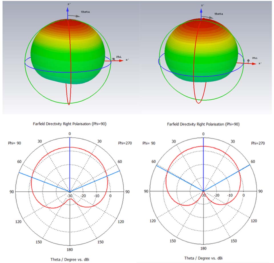
It is challenging to configure a GNSS antenna operating at many frequencies in which the performance at any one frequency is not impaired by mode interactions. Such impairments can have serious consequences for the position accuracy in an urban environment because they adversely affect the cross-polar discrimination: a parameter which is most important for eliminating multipath positioning errors. The architecture of the hexafilar-turnstile antenna has overcome this problem and delivers the circular polarization pattern characteristics illustrated (simulated data) in Figure 2.
Figure 2. Simulated RH circular polarized patterns at GPS L1 (left) and GPS L2 (right).
The figure demonstrates that the antenna is forming cardioid patterns at two frequencies. The 3D graphic is intended to show the omni-directionality and the 2D elevation cuts exhibit the signature cardioid shape which characterize a “spinning-dipole” circular polarization antenna.
It is often suggested that patterns of wide beam-width such as these would not be particularly suitable for positioning in urban canyons where the sky can only be seen in a relatively small solid angle. In fact, the ratio of front-to-back gain is strongly associated with the cross-polar discrimination that is important for position accuracy in urban environments. Patterns of this quality can deliver as much as 30-dB of signal-to-interference advantage in favor of the direct-path satellite signals against signals whose polarization has reversed due to multipath reflection.
Helix Technologies is developing antennas which have two-pole frequency responses that provide two frequencies of optimum cross-polar discrimination that are aligned to the two frequencies of maximum spectral density of an M-BOC or Alt-BOC coded signal, as transmitted by the modern GPS and Galileo satellites respectively. These antennas should be available for test and evaluation in Q2 of 2018.
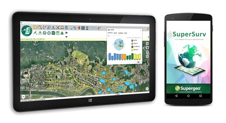
SuperSurv’s NTRIP solution is being enhanced to adopt more RTCM versions and provide a better GNSS positioning service. NTRIP (Networked Transport of RTCM via internet protocol) is a protocol to send GNSS-related data through the internet, which enables users of differential GPS or network real-time kinematic (RTK) to get correction parameters after connecting to the internet. The correction parameters can be used to calculate a more accurate GNSS location. Supergeo’s product team is developing the support for RTCM 3.1, including Types 1021 and 1023.
The scalable A222 GNSS smart antenna is designed for both agriculture and basic indicate systems markets, as well as other markets requiring flexible positioning. The smart antenna has the flexibility to scale and grow as business expands and can be configured from L1-only to multi-GNSS, multi-frequency and real-time kinematic (RTK). It adds a system component so that tractor and farm equipment manufacturers can deliver their own guidance and control solutions to their customers. Designed to excel in challenging environments, the A222 uses Hemisphere’s Athena RTK engine and is Atlas L-band capable. It is easy to mount and customizable. Its dual-serial, CAN and pulse output options are compatible with almost any industry-standard interface. Because the A222 is Atlas-capable, it has the ability to use the new Atlas AutoSeed technology. Atlas AutoSeed allows users to suspend Atlas use for any period, and upon returning to their last location, AutoSeed rapidly re-converges to a high-accuracy converged position. A222 comes pre-configured with Atlas Basic activated.
Locates mobile devices moving indoors and outdoors
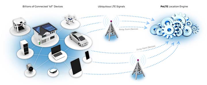
Leveraging ubiquitous LTE signals, the Lite-Touch Architecture calculates positioning in the cloud to efficiently locate devices between indoor and outdoor environments. By offloading computation-heavy location calculations from the device to the cloud, the PoLTE positioning solution makes location positioning available to a wider variety of devices, including those constrained by battery life, memory, processing power, size and cost. This includes IoT-based applications that historically relied on GPS, with its high rate of power consumption, as well as Wi-Fi and Bluetooth with their added size, cost and network complexity.
Enhancements to the SyncServer S600 series of time servers and instruments improve time synchronization over enterprise Ethernet networks and supply timing signals for improved military radar operations and satellite uplink communications. The SyncServer S600 series also meets the timing and synchronization needs of the rapidly evolving networks of enterprise and financial customers, particularly for compliance purposes such as the European MiFID II directive, which specifies highly stringent time accuracy requirements for stock trading systems. The latest release includes support for the IEEE 1588 multiport, multi-profile Precision Time Protocol (PTP), which allows the S600 to operate as an independent grandmaster clock on each Ethernet port — delivering cost savings and network deployment flexibility to customers. This is coupled with a new 10-GbE interface to easily interoperate with a wider variety of network and stock trading topologies.
The HG4930 inertial measurement unit (IMU) is tailored for “straight-out-of-the-factory” integration and use in various non-defense and non-aerospace industrial applications including surveying and mapping, autonomous vehicles and gimbal stabilization. The HG4930 IMU is not classified under an International Traffic in Arms Regulation category; it is free from the burden of an export license for all but a few military-related use cases. The micro-electro-mechanical system (MEMS)-based IMU has been tailored to provide significantly improved gyroscope and accelerometer performance for the environments and use cases experienced by non-aerospace and non-defense users.
The HX-DU2017D is a frequency-hopping OEM modem designed to provide strong anti-jamming and signal receiving capability for complex data-intensive applications. HX-DU2017D is a miniature, dual-frequency, software-selectable 840-MHz and 900-MHz data link modem. It provides power switching of 0.5 W, 1 W and 2 W; 20 ms/30 ms/40 ms/50 ms/ frequency-hopping intervals; and supports point-to-point, point-to-multipoint network. Its full duplex mode ensures secure data transferring and stable long-range communication. The HX-DU2017D also provides short latency of data transmission and communication recovery in millisecond level. It allows fast and secure simultaneous data communication for mission-critical applications, especially in the fields of precision agriculture and UAVs, including unmanned plant surveys, UAV plant protection and automatic mowers. It could be placed on a UAV with its extremely small footprint for tight OEM integration and design flexibility. Meanwhile, its frequency-hopping transmission ensures UAV data security and flight stability.
For small construction, thermal inspections and public safety
The Parrot Bebop-Pro Thermal is a compact quadcopter with two embedded cameras: a stabilized 14-megapixel high-definition front-facing video camera and a FLIR ONE Pro thermal camera. The thermal-imaging camera is positioned in a dedicated module at the back of the drone. Three thermal-imaging setting modes are available: Standard, Dynamic and Hotspot. The Parrot FreeFlight Thermal app innovatively transmits and analyzes images captured by the quadcopter’s cameras. Included is a long-range Parrot Skycontroller 2 remote control.
Pergam gas sensor integrated with carbon-fiber UAV
Pergam gas sensor aboard the Microdrones md4-1000 UAV.
The aerial methane detector mdTector1000 CH4 detects methane gas via a fully integrated aerial package. It has a Pergam gas sensor, mounted and integrated with the Microdrones md4-1000 UAV. In real time users can see aerial shots of detection with the laser sensor. The carbon-fiber-built UAV goes into dangerous areas unsuitable for workers. The mdTector1000 CH4 can be used for natural gas line surveys, tank inspections, gas well testing, plant safety and landfill emission monitoring. The mdCockpit Android app allows users to maintain visualization in flight. A special mdTector app allows users to visualize and present all post-flight data on one map.
Microdrones, www.microdrones.com
UAV tracking antenna
Portable antenna for unmanned or manned aircraft
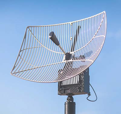
The Octopus UAV portable tracking antenna enables long-range data transmission and is suitable for unmanned and manned aircraft applications. It has a range of more than 100 kilometers and an integrated pointing algorithm. The GPS location of the aircraft is sent over the Airlink IP datalink and received directly by the tracking antenna, making it operational with any existing unmanned aircraft autopilot system. For a manned aircraft, an existing GPS receiver or dedicated GPS receiver can be used.
Brings high-precision positioning and attitude to small UAVs
AsteRx-m2 UAS receiver.
The AsteRx-m2a UAS GNSS OEM engines provides precise and reliable multi-frequency, all-in-view real-time kinematic (RTK) positioning and heading — along with interference technology — with low power consumption. It features Septentrio’s AIM+ interference mitigation and monitoring system, which can suppress a wide variety of interferers. It is designed to bring high-precision positioning and attitude to any space-constrained application, offering a high update rate and low latency output. The AsteRx-m2a UAS provides plug-and-play compatibility for autopilot systems such as ArduPilot and Pixhawk. Event markers accurately synchronize camera shutter events with GNSS time. The board can be powered directly from the vehicle power bus via its wide-range input. It works seamlessly with GeoTagZ software, providing offline re-processed RTK accuracy without the need for either ground control points or a real-time datalink.
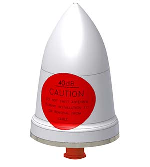
The GPS-TMG-HR timing antennas are designed for Positive Train Control and railroad management, among other markets. They are equipped with high-rejection narrowband filtering to mitigate interference and provide 65-dB rejection of frequencies adjacent to L1 GPS. The GPS-TMG-HR maintains all features of PCTEL’s GPS timing reference platform. The antennas feature a 26-dB amplifier (GPS-TMG-HR-26N) and 40-dB amplifier (GPS-TMG-HR-40N ) and narrowband high rejection filtering to support long-lasting, trouble-free deployments in congested cell-site applications with severe interference around the GPS L1 frequency. The proprietary quadrifilar helix design, coupled with multi-stage filtering, provides superior out-of-band rejection and lower elevation pattern performance than traditional patch antennas.
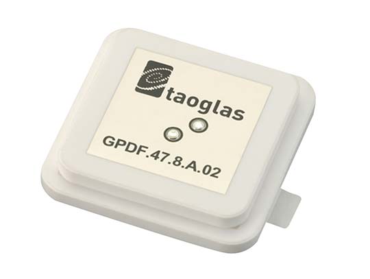
The GPDF.47.8.A.02 is a ceramic GPS L1/L2 / Galileo low-profile, low-axial ratio, embedded stacked passive patch antenna. It is 47.5 x 47.5 millimeters wide and 8 millimeters thick. It is designed for the highest accuracy centimeter-level tracking in telematics applications for positioning technologies. Typical applicable industries are transportation, defense, marine, agriculture and navigation.
The Autonomy Development Platform provides automakers, truck makers and Tier 1 vehicle suppliers the hardware, software, engineering and integration services they need to accelerate development programs for on-road and off-road autonomous vehicles. By combining customized integration and engineering services with GNSS-inertial positioning technologies, the Autonomy Development Platform advances driverless vehicle development projects at every stage of development and commercialization. The platform delivers a navigation solution that is fully customizable and includes integration and engineering services, field-tested hardware and proprietary software for highly accurate positioning. The solution is capable of working with all sensors, including multiple cameras, lidar, radar and ultrasonic sensors, and with all vehicle types at all stages in the development and commercialization cycle. Also, the technology enables highly accurate assessments of the full 360-degree environment around a vehicle to produce a robust representation, including static and dynamic objects, which is critical for successful vehicle autonomy.
TomTom AutoStream is a map delivery service for autonomous driving and advanced driver assistance systems. The service enables vehicles to build a horizon for the road ahead by streaming the latest map data from the TomTom cloud. TomTom AutoStream ensures that the TomTom map data used to power advanced driving functions is the latest, most accurate available, enabling a safer and more comfortable experience. The map-data stream can be customized based on criteria such as sensor configuration and horizon length. It can stream a wide variety of map data including advanced driver assistance systems (ADAS), attributes such as gradient and curvature, and the TomTom HD Map with RoadDNA. This flexibility allows customers to use AutoStream to power a wide range of driving automation functions.
A new company, hoopo, has launched to supply an innovative, accurate geolocation solution for low-power wide area (LPWA) networks. The solution would improve precision for low-power Internet of Things (IoT) asset tracking.
Hoopo’s geolocation enables companies to locate their valuable assets without the significant cost or battery consumption that can be associated with GPS. hoopo’s IoT solutions help companies precisely track specific assets in areas such as shipping ports, airports, car dealer lots, cattle ranches and other asset-dense areas.
Hoopo has received $1.5 million in funding to further grow its business from a group of investors, including the initial investors in Mobileye; Israeli investor Zohar Gilon; and Ben Marcus, CEO of AirMap.
The need to understand and quantify asset location is quickly becoming a requirement for the enterprise and industrial IoT. However, the accuracy of today’s low-power geolocation isn’t precise enough to deliver on the full promise of the IoT.
LPWA networks are becoming the driving force behind smart city and other IoT applications because of their low-cost, low-power consumption, and high-coverage capabilities in rural and urban environments. The long battery life of LPWA devices allows businesses to deploy a maintenance-free device in the field for several years.
“Hoopo is addressing a real business need of companies around the world: cost-effective, yet precise, tracking of their valuable assets with longevity of battery life up to 10 years in the field,” said Ittay Hayut, CEO of hoopo. “LPWA checks off all of the boxes companies need in terms of cost and coverage, and hoopo’s solutions work alongside these LPWA networks to help businesses keep their assets safe, anytime and anywhere.”
Hoopo’s solutions are based on a patent-pending triangulation method that uses LPWA data transmissions to generate a precise location. The solutions suite includes low-cost LPWA gateways and devices, as well as a platform for management and real-time notifications. Companies can receive on-demand geolocation, establish geofences, receive movement alerts, and more, ensuring the protection of their valuable assets.
“Hoopo’s geolocation technology reveals new business verticals that were limited or impossible when using existing technologies because of their high-cost and significant power consumption,” said Menashe Terem, CEO at Tri-logical, a provider of tracking and management solutions.
“Early applications such as asset tracking are just the beginning of what advances in geolocation will enable,” said Eli Fogel, former CTO at Intel and hoopo investor. “Just as the advent of GPS launched a wealth of applications that no one ever thought of before, such as location-based advertising, there are future applications that this next generation of geolocation technology will enable. We’re excited to see what new applications emerge as customers embrace these new precision location capabilities.”
Hoopo is displaying at Mobile World Congress in Barcelona Feb. 26-March 1 in Hall 5, Stand 5D81.
Q: What is the biggest challenge facing designers of multi-constellation GNSS receivers today?
Javad Ashjaee, founder of Javad GNSS: The biggest challenge now is spoofing.
Some years ago the issue was jamming —the hot issue of LightSquared — that would hurt GNSS. To solve that problem we created the J-Shield and showed that J-Shield technology could protect against LightSquared and similar signals. We manufactured dozens of units that were successfully tested by several independent laboratories.
Now GNSS faces the spoofing issue. Reports of Black Sea spoofing and other examples show the urgency of paying attention to this problem. When a spoofer is successful, both position and time are spoofed.
A Nov. 3 CNN video report on this subject gives an example of how little people know about spoofing and about the work that has been done on this subject. The report claims that GNSS technology companies have not done much or spent money on this subject. Obviously the reporter doesn’t know what we have done, as I will report here.
I’ll review the spoofing methods and how we counter them.
Source: Javad GNSS
Spoofers use three methods: One simple way is to broadcast GNSS-like signals that provide the wrong ranging information which, when used, creates wrong position and time solutions. Most probably this is the method that Prof. Todd Humphreys used to spoof the GNSS receiver on the $80 million yacht [“GNSS Lies, GNSS Truth,” November 2014 GPS World.] This method fools the GNSS receiver into ignoring the correlation peak of the real satellite signal and using the correlation peak of the spoofer signal. To deal with this type of spoofer we take advantage of the 864 tracking channels and over 130,000 fast acquisition channels of our TRIUMPH chip. We assign more than one channel to each satellite signal and we track all their peaks: The real peak and the spoofer’s peaks. Then in Step 1, below, we exclude all signals with more than one correlation peak.
Method Two is broadcasting spoofed signals for satellites that are below the horizon in the spoofed area or for satellites that do not exist. In this case only one correlation peak exists. Our equipment and OEM boards can download valid and certified almanac data from our website to know the status of satellites and their visibility ahead of their mission. Almanac data can be used for several weeks.
Method Three is to cover the signal of a visible satellite with noise and on top of the noise add the spoofer signal with more power. We recognize such spoofers by their unreasonable signal power and the background noise.
In the first counter-spoofing step we ignore these signals:
Those with more than one peak;
Those that according to our almanac should not be visible;
Those with unreasonably high or inconsistent signal-to-noise ratio (SNR);
Systems whose satellites all have similar SNR.
Satellites that do not generate complete multi-frequency signals (spoofers usually generate only C/A code).
After removing all questionable signals, we use the remaining signals to compute our approximate position. We need at least 4 signals from the many available signals of GPS L1, L2P, L2C, L5, GLONASS L1, L2, L3, and the many signals of BeiDou, QZSS and IRNSS.
In the second step we validate all questionable signals against the approximate position that we have calculated and keep only those that pass our validation. We then re-compute the more precise position using all good signals. We consistently throw away the spoofer correlation peak and use the real satellite signal.
If all signals of all satellites are spoofed, then we warn the user to ignore the GNSS signals and use some other sensors (like compass and gyro) to get out of the spoofed area. A spoofer that can spoof all signals of all satellites will be very expensive to build and deploy.
In a very difficult situation, the user can enter their approximate position to quickly understand if spoofers exist, and then identify them.
All the counter-spoofing methods that I have discussed here are the subject of patents for which we have applied.
Since currently most of spoofers spoof the L1 C/A code, we can simply initially ignore the C/A signals to compute the initial approximate position and use it to identify the spoofed signals.
It is vital that in areas that spoofing danger exists, users employ OEM boards that provide more satellite systems and more signals, rather than using a simple GPS C/A code, for example.
Finally I would like to challenge Prof. Todd Humphreys [professor and director, Radionavigation Laboratory, University of Texas-Austin] to spoof any of our receivers that have this anti-spoofing option. We offer this as an option on all of our OEM boards.
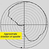
An experiment in an anechoic chamber with a JAVAD GNSS TRIUMPH-LS shows the approximate orientation of the spoofer (at 283° azimuth.)
Javad GNSS advises that with its equipment it is possible, when a spoofer is detected in the area, to identify the direction from which the spoofing signals are coming.
Hold the receiver antenna horizontally and rotate it slowly (one rotation in 30 seconds) to determine the angle at which satellite energies become minimum.
The spoofer’s direction lies behind the null point of the antenna reception pattern.
An experiment in an anechoic chamber with a Javad GNSS Triumph-LS shows the approximate orientation of the spoofer (at 283 degree azimuth.)
NavVis, a mobile indoor mapping, visualization and navigation company, released new mapping software that significantly improves the accuracy of simultaneous localization and mapping (SLAM) technology in indoor environments, such as long corridors, the company said.
The software update will be available for users of the NavVis M3 Trolley and will significantly improve the accuracy of the resulting maps and point clouds. NavVis’ mobile mapping system, the M3 Trolley, builds upon SLAM to increase speed and efficiency when scanning buildings.
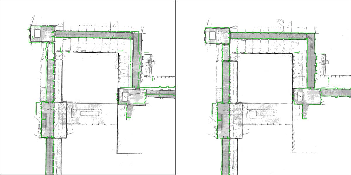
The images below demonstrate the impact of NavVis Precision SLAM technology. The left image depicts a long corridor mapped with a conventional SLAM system where the above-mentioned drift error has occurred. The green outline shows how the map deviates from the true structure. The image on the right shows the significantly improved map accuracy obtained when mapping the same area using the M3 Trolley with the new Precision SLAM technology.
Image: NavVis
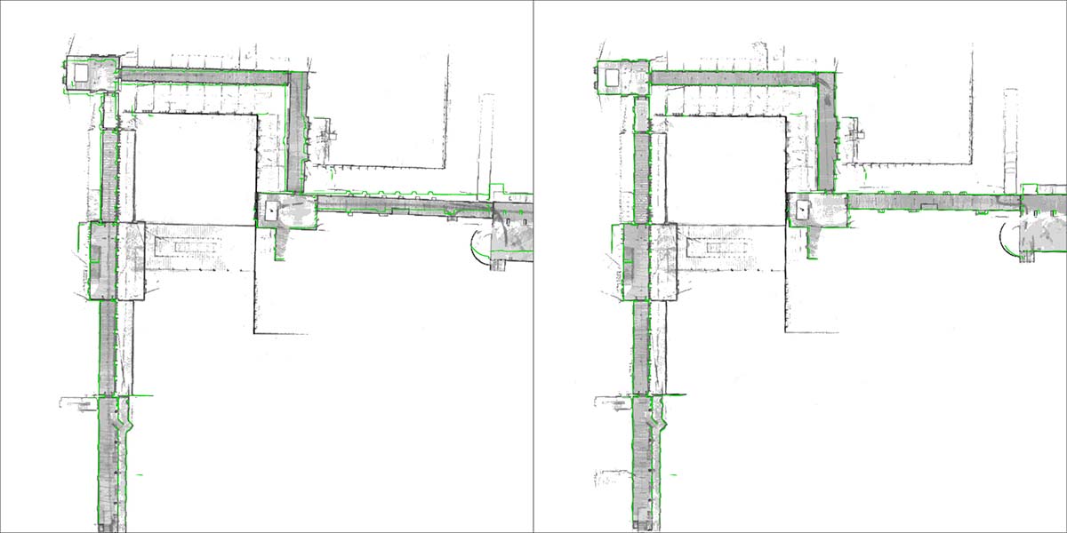
Here is a closer look:
Image: NavVis
SLAM is a technique originally developed by the robotics industry that is now increasingly being used in surveying and autonomous driving technologies. It solves a core problem that long plagued robotics engineers by enabling a device to determine its location while simultaneously mapping an unknown environment. This is done by chaining millions of measurements into a trajectory estimate.
However, even when a device captures highly accurate individual measurements, chaining them will result in an accumulation of noise and tiny measurement uncertainties. Over time, the estimated motion will start to deviate from the true motion (drift error). This can often be observed as a slight bending of long corridors that are actually straight. All available SLAM systems — regardless of whether these use LIDARs or other sensors — are inherently affected by this phenomenon.
The NavVis Precision SLAM technology significantly reduces drift error and improves the SLAM accuracy. This is particularly evident in cases where complementary techniques such as loop closures cannot be deployed, if, for example, the building’s layout does not allow for it.
Precision SLAM even improves accuracy when SLAM anchors are used to incorporate ground control points into the mapping process.
“I am very excited about our new Precision SLAM technology,” said Stefan Romberg, head of mapping and perception at NavVis. “We are always striving for the highest possible map and point-cloud accuracy and improving SLAM is a critical component to being successful. It is widely known among SLAM developers and users that complementary approaches such as loop closures or ground control points are needed to achieve a high accuracy.
“However, with the Precision SLAM technology we have developed an approach that not only nicely complements the former techniques but is especially evident when these have little effect or cannot be used.”
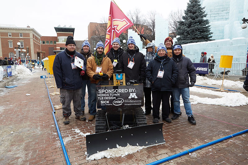
The ION Autonomous Snowplow Competition, held in cooperation with the ION North Star Section, is an international event open to college and university students, as well as the general public. According to ION, the competition challenges teams to design, build and operate a fully autonomous snowplow using state-of-the-art navigation and control technologies.
Eleven teams entered the competition, and eight of those teams successfully completed all the phases of the competition. Each team used a variety of navigation systems, including lira, optical navigation systems, inertial instruments, magnetic sensors, ultra wide-band radio reflectors, visual odometry, GNSS and differential GPS, to rapidly and accurately clear a designated path of snow.
Teams were judged based upon their cumulative scores earned throughout the competition phases, including presentations and dynamic vehicle events.
The first place team was the University of Minnesota’s “Snow Squirrel” team. The team was awarded $7,000 and a Golden Snow Globe Award, and is invited to present during the ION GNSS+ 2018 conference Sept. 24-38 in Miami. The second place team was the Dunwoody College of Technology’s “Wendigo 2018” team, which was awarded $4,000 and a Silver Snow Globe Award. Finally, the third place team was North Dakota State University’s “Thundar 3.0” team, which received $2,000 and a Bronze Snow Globe Award.