Category: Applications

  • Driverless conference focuses on strategies for autonomous car

    With automakers and Silicon Valley technology companies rolling out their strategies for the autonomous car, keeping on top of the latest technology, worldwide markets and regulation will be critical. Enter Driverless, a conference that will be held March 22-23, 2016, at the Crowne Plaza Hotel, San Francisco Airport.

    Attendees at the conference can find out what technology and markets will prevail from both Detroit and Silicon Valley perspectives from some of the most important executives in the business, explains event organizer and GPS World LBS Editor Kevin Dennehy.

    Driverless will feature more than 30 executive speakers covering the most important issues facing the autonomous vehicle industry. Driverless is an exclusive one-day conference that features an early bird reception on the evening before, a hosted luncheon, and an industry-best two-and-a-half hour reception with more than 15 exhibits from prominent companies.

    Those attending can learn the answers to these questions:

    • What technological, social and legal issues face ADAS and autonomous vehicle progression?
    • What technologies are solving the high cost of rolling out autonomous systems?
    • How can companies adequately test vehicles?
    • How will car sharing revolutionize the autonomous vehicle industry?
    • Who are the most innovative players and what are their intentions?
    • What are consumer expectations?
    • What systems are evolving… and for what markets?
    • Who owns this market? The technology companies or traditional automakers?

    Learn more at the conference website.

  • IZT Solutions’ over-the-air system tests GNSS receiver performance

    German research organization Fraunhofer Gesellschaft has developed and presented an over-the-air (OTA) wave-field synthesis system for test and certification of GNSS receivers. The testing platform is at its Fraunhofer IIS Facility for Over the Air Research and Testing (FORTE) in Ilmenau, Germany.

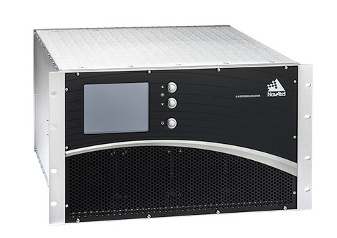
    The innovative and complex OTA test system is based on hardware and software solutions from IZT GmbH, such as powerful RF receivers and high-performance signal generators.

    The demonstrated setup to test GNSS receivers represents a new approach that — in contrast to conventional conducted and open-field tests — realistically emulates real-world scenarios under controllable and repeatable conditions, enabling the realistic comparison of receivers and algorithms. The OTA test system is cost-effective, flexible and scalable.

    The newest generations of mobile communication systems employ multiple antennas for transmission and reception, such as LTE, LTE-A, WIMAX and Wireless LAN. Multiple Input Multiple Output (MIMO) OTA test systems are typically deployed for certification, performance testing and product evaluation of broadband wireless devices. The related devices have to be tested in their related environments.

    In contrast to mobile phones, GNSS receivers are extremely susceptible to all types of interference. Hence, the goal was to develop a new testing method for interference robustness of GNSS receivers.

    The OTA Test Approach

    The OTA test laboratory comprises a satellite signal emulator (Spirent) used as signal source, several OTA channel emulators used for wave-field synthesis that are able to emulate any electromagnetic environment in an anechoic chamber, and several OTA illumination antennas. The OTA channel emulators from IZT GmbH support 8 input and 32 phase coherent output channels (up to 256 logical channels) in the frequency range of 1 to 6 GHz, and provide the output signals to the OTA illumination antennas. Note that the final extension of the system based on the IZT components will have 12 x 32 channels.

    The unique test environment developed at FORTE together with IZT GmbH excels in its great flexibility regarding possible applications in communications technology. The new OTA emulation approach enables realistic radio channel emulation taking into consideration multipath propagation, multi-frequency, and multi-user scenarios.

    The OTA system supports emulation of complex channel impulse responses of nearly unlimited length. Besides GNSS equipment, the test system can be applied for LTE and Cognitive Radio (CR), sensor networks (including energy networks and smart metering) or car-to-car and car-to-infrastructure communications.

    The Innovationszentrum für Telekommunikationstechnik GmbH IZT is a spin-off of the Fraunhofer-Gesellschaft, Germany’s leading institution for applied research. Founded in 1997 in Erlangen, the company emanated from the Fraunhofer Institute for Integrated Circuits (IIS). It specializes in advanced digital signal processing and field programmable gate array (FPGA) designs in combination with high-frequency and microwave technology.

  • ŠKODA App Lets Kids Drive along with Parents

    ŠKODA App Lets Kids Drive along with Parents

    Photo: ŠKODA

    Czech automaker ŠKODA is offering a tablet game that gives kids in the backseat the opportunity to follow along as their parent drives.

    With the ŠKODA LittleDriver app, children can imitate the driver’s actions using real data from the car. The app makes use of ŠKODA’s SmartGate interface, which uses Wi-Fi to send vehicle data to a connected device.

    LittleDriver is fully interactive: children can copy the actions of the real driver and collect points when they are correct. Steering, acceleration, turning, braking — everything that the driver does, the player can imitate on a tablet in real time. Speed, fuel level, brake status and oil pressure are also displayed.

    At the end of the game, points earned can be used to design a virtual ŠKODA, which can be configured individually in the app. The ŠKODA LittleDriver app is available on the Apple and Android app stores, and is aimed at ages 9–12.

    Skoda-littledriver-3-W Skoda-littledriver-app-W

  • GPS Shape-Changing Device Guides through Touch

    GPS Shape-Changing Device Guides through Touch

    (Photo: Yale News)
    (Photo: YaleNews)

    A handheld GPS device uses touch to help you determine where to walk. Made with a 3D printer, the cube-shaped “Animotus” was designed with the visually impaired in mind, reports YaleNews.

    Designed by Adam Spiers, a Yale University post-doctoral associate in mechanical engineering, the Animotus is designed in layers, with the receiver in the middle. The top layer revolves to show what direction to walk, extending to indicate distance.

    When it stops twisting and returns to its cube shape, you’ve reached your destination. It can be programmed wirelessly on a computer or a smartphone.

    Spiers said he chose touch for guidance over sound because of the many aural distractions.

    (Diagram: Yale News)
    (Diagram: YaleNews)

    The Animotus was tested in London in an immersive production of a play based on the novella Flatland, about a two-dimensional world. Using the Animotus, the audience was guided through the church to uncover the plot. When the Animotus signaled participants to stop, narrative and sound effects took over. The performing company includes sight-impaired members.

    The Animotus was demonstrated at the World Haptics Conference in June at Northwestern University and received “quite a bit” of interest, Spiers said.

    See a video about the Animotus here:

  • El Chapo’s Accomplices Used GPS

    El Chapo’s Accomplices Used GPS

    Joaquin “El Chapo” Guzman’s accomplices knew where the world’s most wanted and powerful drug lord was at all times because he had television in his cell that has a GPS tracking device inside of it, according to the Mexican newspaper La Jornada.

    Prison officials seized all electronic devices from all the cells inside the maximum security jail in Toluca after El Chapo’s escape through a mile-long tunnel on July 11.

    The GPS device would explain why El Chapo’s associates were able to precisely excavate a tunnel into his cell.

    The red circle shows the television with the GPS tracker inside.
    The red circle shows the television with the GPS tracker inside.
  • University of Georgia Teaches Precision Ag with Corn Maze

    University of Georgia Teaches Precision Ag with Corn Maze

    Vellidis' precision agriculture class helped develop the maze using GPS technology. (Photo courtesy University of Georgia)
    Vellidis’ precision agriculture class helped develop the maze using GPS technology. (Photo courtesy University of Georgia)

    University of Georgia precision agriculture students used GPS to design a corn maze in honor of football coach Mark Richt.

    George Vellidis, a UGA crop and soil sciences professor, gave his precision ag students the opportunity to experience GPS technology firsthand by having them develop a corn maze at a nearby farm.

    “I’ve been teaching precision agriculture at the UGA Tifton Campus since 2003. We’ve been teaching GPS from day one because GPS is a critical part of precision agriculture. Everything we do with precision agriculture has coordinates, so we can collect our data through GPS,” Vellidis told the newspaper. “It’s a great experience for the students to go out and help with the corn maze. They get to do a fun activity while learning how to use GPS.”

    Covering 6.1 acres, the maze is the biggest ever constructed at Rutland Farms, and received national coverage on ESPN.

    Students have been impressed by how easy GPS technology is to use and how beneficial it can be to farmers. “I’ve used it to go back after we’ve already installed moisture sensors earlier in the season and I’ve used it to find the sensors much later in the season,” Sydni Barwick, Vellidis’ student and student worker in irrigation for UGA Cooperative Extension.

    “When, for example, a corn crop is eight feet high, you can’t see across that field, so there’s no way to find the sensors without GPS. Using the (GPS) system is great for things like that because it has an accuracy of about 3 feet,” she said.

    Learn more about the project here.

    Students in George Vellidis' precision agriculture class helped develop the corn maze at Rutland Farms.
    Students in George Vellidis’ precision agriculture class helped develop the corn maze at Rutland Farms. (Photo courtesy University of Georgia)
  • National Map Corps Updates Volunteer Badges

    VGI,-new-badges-W

    The National Map Corps has updated the recognition badges that it awards for participation in its crowdsourcing mapping project. Volunteer “citizen scientists” who collect manmade structure data such as police stations, schools, hospitals and cemeteries, to provide more precise spatial data for the USGS web-based mapping products can earn points and virtual badges.

    Due to continuous project growth and popularity, TNMCorps has added more badge levels and revised the current awards. More than 160,000 points have been edited or verified to date.

    The project started in 2012, and since that time, the increasing number of volunteers have verified, edited, deleted and created more than 160,000 structures points. In appreciation for the efforts of these “free” mappers, those who reach certain milestones are celebrated in the form of virtual badges.

    The newly designed badges showcase the same classic surveying tools and aerial data collection methods, but have been colorfully updated and highlight a variety of amazing landscapes across the United States.

    A second set of badges based on aerial data collection was introduced a year ago as some extra-energetic volunteers quickly surpassed the first set of badge levels. Currently, 11 possible badges can be earned beginning with the Order of the Surveyor’s Chain (25 points) and ending with the Squadron of Biplane Spectators (6000 + points).

    As volunteer map editors attain each level, a congratulatory email is sent to the awardee with a description of the badge and encouragement to achieve the next level. With permission, volunteer accomplishments are highlighted on TNMCorps Recognition page, and The National Map Twitter (#TNMCorps).

    NatlMapCorps-W


  • Rockwell Demonstrates Next-Gen Military Test Range System

    During the first week in September, Rockwell Collins completed Contractor Test and Evaluation flights at Eglin Air Force Base, Fla., for the Common Range Integrated Instrumentation System (CRIIS). The demonstration included ground-to-air uplink of GPS correction messages and network services from multiple data-link towers.

    In cooperation with the CRIIS System Program Office (SPO), contractors and the University of Iowa Operator Performance Laboratory (OPL), 13 test flights were conducted using an L-29 from the University of Iowa OPL. Throughout the testing, the high reliability of the CRIIS equipment resulted in all test flights being performed as scheduled. Only a single test flight was scrubbed due to bad weather. All the flights were conducted using production form, fit, function airborne and ground equipment.

    The CRIIS program fulfills critical Department of Defense (DoD) requirements to provide Time, Space, Position Information (TSPI) and additional platform test data, while employing a more robust, spectrally efficient data link, including Multiple Independent Levels of Security (MILS). The MILS encryption recently completed certification on the program, and is capable of simultaneously protecting four levels of Top Secret through Unclassified data flowing between aircraft and ground components.

    “These flight tests demonstrate the mature, production ready level that the CRIIS program has reached,” said Tommy Dodson, vice president and general manager of Surface Solutions for Rockwell Collins. “Tests were an end-to-end validation of the complete CRIIS system using production representative hardware and software. This testing validated that the next generation of secure, common test and training instrumentation is mature.”

    Rockwell Collins is the prime contractor and systems integrator for the next-generation military test range system that will replace the Advanced Range Data System (ARDS) currently in use at major U.S. military test ranges. CRIIS equipment will support a variety of platforms, including advanced fifth-generation aircraft, and implements the DoD’s vision of common test and training infrastructure for improved operational realism.

    The following key functions were demonstrated on these flights:

    • End-to-end system validation with production representative hardware
    • High confidence in ability to meet TSPI performance requirements
    • Data-link network ingress after takeoff
    • Ground-to-air uplink of GPS correction messages and network services from multiple data-link towers
    • Air-to-ground downlink of TSPI messages
    • High dynamic scenarios involving a total of 133 dynamic maneuvers representative of flight profiles fighter jets undertake during air combat training

    In addition to the multi-level secure ground equipment, the CRIIS flight hardware is configurable in either a pod mounted package or internally mounted on aircraft. This gives CRIIS the flexibility to adapt to use by a wide range of aircraft from all over the world, and the ability to fully integrate those aircraft into complex training scenarios.

    Following the completion of CT&E, the CRIIS SPO will conduct Government Test and Evaluation (GT&E) later this year to support a planned final Production Readiness Review in the near future.

  • Configuring the TRIUMPH-LS to Receive 5-Hz ‘Beast Mode’ Corrections

    Configuring the TRIUMPH-LS to Receive 5-Hz ‘Beast Mode’ Corrections

    By Matt Johnson

    In a previous article titled JAVAD GNSS 5 Hz “Beast Mode” RTK Base Station Corrections Reduce the Time to Acquire a Fix by 72 Percent, the benefits of RTK base station correction rates greater than 1 Hz were discussed. This article will detail how to configure a JAVAD base station and radio to transmit 5-Hz corrections to a JAVAD TRIUMPH-LS. This process includes the following steps:

    • Update the TRIUMPH-LS firmware and software.
    • Update the Options Authorization File (OAF) of your base station.
    • Update the firmware of your UHF radio.
    • Configure the UHF radio parameters and start the base station.
    • Update the TRIUMPH-LS Firmware and Software.

    The first step is to update the TRIUMPH-LS to the latest software and firmware. Javad provides all software and firmware updates free of charge. Updates can be easily downloaded and installed when the TRIUMPH-LS is connected to the Internet through Wi-Fi or with a network LAN cable. Press the Support button found on the home screen and then choose Software Updates to search for updates. If updates are found, press Update to download and install the updates.

    Update Software screen showing that an update of J-Field is available.
    Update Software screen showing that an update of J-Field is available.

    Update the Options Authorization File (OAF) of your base station.

    The next step is to check and update the OAF of your base station. Connect your base station to your PC with a USB cable and connect to it through NetView. Navigate to the Options tab in NetView and check to see if your receiver has the “RTK mode (Hz)” option of 10.

    NetView Option tab showing the RTK mode (Hz) option has a value of 10.
    NetView Option tab showing the RTK mode (Hz) option has a value of 10.

    If you do not have this option, press the Upload “From Internet” button to update your options. JAVAD GNSS is giving this option free of charge to all users who have purchased an RTK receiver.

    Update the Firmware of Your UHF Radio.

    A recent update is needed for the UHF radios to work when a call sign is being broadcast with corrections rates faster than 1 Hz. Download the latest firmware from http://javad.com/jgnss/support/update.html and follow the instructions on this page to install this firmware. When launching ModemVU on your PC, be sure to right click on it and choose “Run as administrator”.

    Configure the UHF Radio Parameters and Start the Base Station.

    To start the base with 5-Hz corrections, the Broadcast Period must be changed to 0.2 seconds in the Base/Rover Setup. “RTCM 3.0 Min” should be chosen as the correction format. This format only broadcasts the RTCM messages needed for RTK positioning and excludes information containing signal-to-noise (CNO) and full milliseconds for code observations. A modulation must be selected that has a sufficient link rate to transmit increased data rates with 5-Hz corrections. With the Channel Bandwidth set to the FCC’s limitation 12.5 kHz, the D16QAM modulation must be used. With 2-Hz corrections (0.5 second broadcast period) D8PSK modulation can also be used.

    image005
    UHF Modem Link Rates (bps)

    Modulations with greater link rates have decreased receiver sensitivity to demodulate the signal; the downside to choosing modulations with higher link rates is that they are more subject to interference and data loss when the signal is weak. Field tests have found that D16QAM modulation decreases the working range of the radio approximately 20 percent compared to DQPSK modulation.

    Radio settings for 5-Hz corrections.
    Radio settings for 5-Hz corrections.
    image007
    Radio settings for 5-Hz corrections.

    After these settings in Base/Rover Setup have been modified, press the To Base button to apply them, and then the Start Base button to start broadcasting with the configured setup.

  • NovAtel to Develop WAAS G-III—Galileo Reference Receiver for FAA

    NovAtel to Develop WAAS G-III—Galileo Reference Receiver for FAA

    NovAtel's WAAS G-III—Galileo Reference Receiver.
    NovAtel’s WAAS G-III—Galileo Reference Receiver.

    The U.S. Federal Aviation Administration (FAA) and NovAtel have exercised a bilateral option to produce a Wide Area Augmentation System (WAAS) G-III—Galileo prototype receiver. Maintaining core NovAtel WAAS G-III functionality for GPS and SBAS signal processing, the new receiver will operate in the WAAS reference station test environment to facilitate research on multiple GNSS constellation utilization.

    The prototype receiver will also add functionality to support tracking and demodulating associated navigation data for Galileo satellites including:

    • Galileo E1 and E5a tracking
    • Ephemeris and almanac reporting/processing from E1 or E5a
    • Automatic channel assignments
    • Time solution computed from Galileo
    • Correlator information for signal deformation on Galileo signals

    The WAAS G-III—Galileo prototype receiver will be developed on NovAtel’s existing WAAS G-III receiver hardware and application software, and delivered as a field-loadable firmware package. The WAAS G-III—Galileo receiver will not be qualified to DO-178B Level D as part of this contract.

    NovAtel’s WAAS G-III reference receiver platform was designed with expandability and multi-GNSS SBAS evolution in mind, and can be customized to meet the needs of individual satellite networks. NovAtel has already delivered G-III based reference receivers to several programs worldwide, including the WAAS G-III receiver (US WAAS, FAA), IRIMS G-III receiver (India IRNSS, ISRO),  and QZSS G-III receiver (Japan QZSS, NEC) variants.

    The company’s reference receivers and uplink station equipment have been a central element of the U.S. WAAS since its inception. The WAAS third-generation reference receiver (G-III) uses fully updated hardware, and tracks all GPS signals including the legacy GPS L1 C/A, L2P(Y) (semi-codeless), and the modernized L2C, L5, L1C signals as well as the WAAS L1 C/A and L5 signals.

    The WAAS G-III reference receiver provides a rich set of range measurement data, signal integrity metrics, and logs for processing by the system’s data communication processor, NovAtel said. The WAAS G-III – Galileo prototype receiver is the first G-III platform evolution for the FAA, an important step towards possible GPS + Galileo dual-GNSS SBAS operations in the future.

  • Aeryon Named UAV Partner for Microsoft Video Platform for Police Agencies

    Aeryon Named UAV Partner for Microsoft Video Platform for Police Agencies

    MAPP

    Aeryon Labs is partnering with Microsoft on its new Microsoft Advanced Patrol Platform (MAPP) vehicle. Microsoft has chosen Aeryon’s SkyRanger UAV to demonstrate aerial image and data capture for MAPP.

    Aeryon Labs is a provider of small Unmanned Aerial Systems (sUAS) for military, public safety and commercial operators worldwide.

    “Law enforcement organizations throughout the world rely on Aeryon sUAS to collect aerial intelligence wherever and whenever they need it,” said Dave Kroetsch, president and CEO of Aeryon Labs Inc. “Including SkyRanger within the MAPP vehicle rounds out the comprehensive suite of technologies and highlights the value of aerial intelligence for ground-based personnel.”

    Aeryon Labs' SkyRanger UAV helps law enforcement
    Aeryon Labs’ SkyRanger UAV provides real-time intelligence to law enforcement. (Photo: Aeryon Labs Inc.)

    MAPP will connect its drivers to helpful and easy-to-navigate information, Aeryon said. Currently, patrol officers spend vast amounts of valuable time bound to their cars, clicking between windows on bulky, often dated laptops. MAPP will consolidate the many elements officers must keep track of — providing dispatch information, driving directions, suspect history, a voice activated license plate reader, a missing persons list, location-based crime bulletins and statistics, a feed of shift reports and more.

    For first responders, surveillance teams and investigators, high-quality aerial imagery provides the real-time intelligence needed to assess a situation immediately, ensure safety on the ground, and capture detailed evidence and forensics. By integrating aerial images from Aeryon sUAS with other cutting-edge hardware and software solutions, the MAPP program sets a new technological standard in policing and helps officers operate with better awareness, efficiency, mobility and safety.

    Aeryon Labs is showcasing the integrated solution at the IACP 2015 law enforcement and public safety conference, being held Oct. 25-27 in Chicago.

  • U.S. Army Is Seeking GPS-Denied Technology for UAS

    The U.S. Army’s Armament Research, Development and Engineering Center (ARDEC), located at Picatinny Arsenal in north-central New Jersey, has issued a sources sought notice for technology it can use for a variety of unmanned systems.

    The notice says that technologies developed for the Autonomous Unmanned Systems Teaming and Collaboration In GPS Denied Environments program (AUSTC) could be used for small UAS, underwater vehicles and ground vehicles.

    The center plans to to “identify, invest, mature and transition revolutionary/game-changing autonomous unmanned sensing technologies.”

    “The AUSTC program employs a ‘think-tank’ and modified ‘skunk-works’ approach to identify and determine best path forward for new and game-changing technologies that may be available or in development to achieve U.S. Army RDECOM-ARDEC interest Sensitive Target Site Exploitation (STSE) mission,” the notice reads.