Tarun Bhattacharrya, Hassan El-Sallabi, Jian Zhu, Jeff Wu, and Per Enge.
Radio-Frequency Pattern Matching
By Tarun Bhattacharrya, Hassan El-Sallabi, Jian Zhu, Jeff Wu, and Per Enge
Radio-frequency pattern matching (RFPM) is the engine that enables the use of mobile-phone signals to locate wireless devices in any environment, including dense downtown areas and indoors. This exciting technology leverages the power of the database to improve location accuracy to within 50 meters in even the toughest signal environments. Significant advances in RFPM technology have been made over the last 10 years. The system described here is deployed in more than 24 wireless networks to provide the location of E-911 callers and help save lives. For simplicity, we focus on the RFPM using signal strengths even though the technology also works with arrival times, signal-to-noise ratios, differential signal strengths and any signal parameter that varies in a predictable fashion over the coverage area.
Like GPS, RFPM is based on correlation. However, it does not correlate a received spread-spectrum code with a replica code stored in the receiver. Rather, it correlates the signal strength of cell-phone signals measured by the roving phone to a database that contains a map of those signal strengths for the covered area. Consider Figure 1. It shows this key correlation operation. As shown, the database contains a k-vector for each location within the covered area, where the k elements give the estimated strength for the k mobile phone signals that can be received at the given grid point. These k-vectors are typically stored over a 10- or 30-meter grid. This grid of predicted signal strengths is built in advance and is updated only when the topography of the wireless network changes. Thankfully, base stations do not generally move!
Figure 1. Radio-frequency pattern matching of n-vector from mobile user to k-vectors within database.
The mobile phone provides the network measurement report (NMR) in real time. This report does not require any network hardware or on-phone software beyond that required by the 2G, 3G and LTE standards for all mobile phones. Thus, the Polaris Wireless solution is capable of locating any mobile phone over any air interface. The NMR is also shown in Figure 1. It contains an n-vector of received signal strengths, where k ≥ n. A multiplicity of n-vectors are backhauled to the server that contains the database. They are correlated with the k-vectors, and the estimated location of the mobile phone is the location associated with the maximum correlation.
For Example, San Francisco
Figures 2, 3, and 4 explode the RFPM database for the financial district of San Francisco. Figure 2 is the top view, and the Bay Bridge is shown heading northwest across the Bay. The numbered black dots are some of the base stations in action for this area. Figure 3 digs down one level. It shows the individual k-vectors contained within the database. As shown, this database is based on a 30-meter grid. Figure 4 is a super-zoom that explodes the individual k-vectors. As shown, each of these vectors contains an element for each base station that can be received at the given location. In Figure 4, each element is color coded to correspond to the strength for the signal from the given base station.
Figure 2. Coverage area of an RFPM database within San Francisco.Figure 3. Zoomed view of San Francisco database showing a multiplicity of k-tuples.Figure 4. Radio-frequency pattern matching of n-vector from mobile user to k-vectors within database.
Building the Database
RFPM accuracy depends strongly on the quality of the database, which needs to be built with great care. In fact, signal propagation depends on the network topology including:
◾ antenna location, heights, patterns, effective radiated power, tilt, and azimuth
◾ cell type, such as micro-cell, macro-cell, indoor or distributed antenna systems.
Signal propagation also depends on information available from geographical information systems such as:
◾ tree canopy
◾ height of buildings and terrain
◾ topography (water, open area, suburban, urban)
◾ roads.
With this data, the signal strength radiating from a base station can be estimated. This is not a simple business. For example, the calculation must identify the points where terrain or buildings interrupts the ray from the transmitter to the receiver. It must also identify the points where these obstacles break the Fresnel zone that surrounds the ray.
Finally, these open-loop predictions are tuned based on a sparse set of measurements. Once tuned, the database is time invariant or nearly so. If minor changes are made to the network topography, the open loop predictions alone are sufficient to accommodate the changes. If network changes are significant, such as the building of many new base stations, then the open-loop predictions must be updated, and a new set of measurements used to tune the predictions.
Figure 5 shows a typical map of signal strengths surrounding one mobile phone in a completely open area. Absent terrain and buildings, the signal strengths vary rather smoothly. Figure 6 is for one of the transmitters in the San Francisco financial district, which is a much more complicated urban environment due to the dense concentration of high-rise buildings and uneven terrain. In this case, the signal-strength signature has a gratifying abundance of detail. This detail enables RFPM to work very well in the complicated signal environments that we find in downtown areas and also indoors. In short, RFPM benefits from the buildings and terrain that hinder satellite measurements.
Figure 5. Predicted signal strength for a transmitter surrounded by open ground.Figure 6. Predicted signal strength for one transmitter in the San Francisco financial district.
Performance and Summary
RFPM works well. It provides high accuracy in a in a wide variety of environments. Polaris Wireless routinely tests the accuracy of its solution in urban settings. Table 1 shows the results of such evaluations, based on measurement sets that are not used to tune the database.
Table 1. Evaluations based on routine accuracy tests of RFPM in urban settings.
These days, robust navigation for downtown and indoors is based on an expanding suite of location technologies. These include: assisted GPS, new satellite constellations (Galileo, GLONASS, Compass, and so on), inertial measurements, Wi-Fi ranging, and signals from low-Earth orbit. RFPM, and its unique reliance on database-derived location, should remain an important part of this mix.
Tarun Bhattacharrya is vice president of research at Polaris Wireless. He earned his Ph.D. in electrical engineering from the Indian Institute of Science.
Hassan El-Sallabi received his D.Sc. in electrical and communications engineering from Helsinki University of Technology, Finland. At Polaris he works on RF propagation modeling.
Jian (JET) Zhu received his Ph.D. in electrical engineering from Georgia Institute of Technology; he is a research engineer at Polaris.
Jeff Wu focuses on algorithm development for propagation modeling at Polaris, and is a Ph.D. candidate in electrical engineering at Stanford.
Per Enge is the Kleiner Perkins professor of engineering at Stanford University, where he directs the Stanford Center for Position, Navigation, and Time. He is also a technical advisor to Polaris Wireless.
Augmented reality delivers two important military capabilities to the warfighter: situational awareness and precision piloting capabilities, both key to survival on the battlefield. Look-ahead drive-to-position, based on accurate GPS positions, extends the importance of GPS to high-speed operation or very close maneuvering situations where humans cannot cycle through a chart or map display, then place themselves in the real world to make maneuvering decisions.
By Thomas Zysk, Jeffory Luce, and James Cunningham
Augmented reality (AR) is a concept in daily use in the modern technology vernacular. In one popular form, AR enhances football broadcasts with overlaid information such as the first down line. A much more robust capability for application in high-performance navigation systems uses accurate GPS and heading sensors to geographically register a virtual world accurately over a real-world, real-time view. In a military context, AR can provide critical context to situational awareness.
AR for military use was originally developed as a maritime equivalent to the aviator’s heads-up display. Evaluations using a task-load index function showed a 342 percent improvement in side-task operator performance when using AR. Operators do not have to make the mental conversion from 2D (map or chart view) to 3D real-world view. This translation is where errors can be made in high-stress scenarios and forms the root cause of many accidents. AR provides a game-changing capability to enhance warfighter performance when it matters and is invaluable during high-stress, dynamic operations.
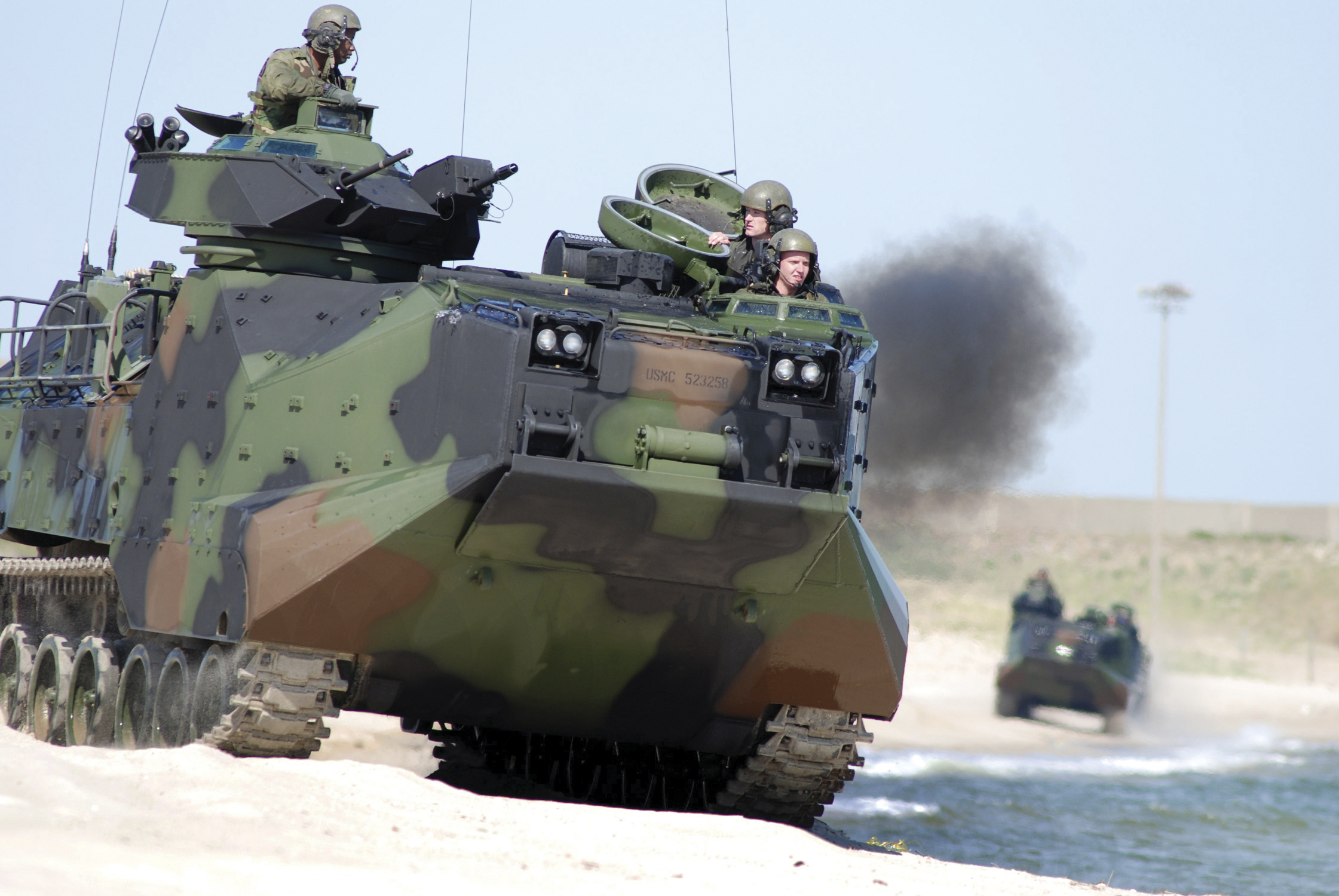
Amphibious assault vehicle (AAV), U.S. Marine Corps.
In this navigation context, AR was developed for use in low-visibility situations, such as navigating in dense fog or at night during lights-out missions. The technology can provide a visual depiction of critical points of interest, regardless of real-world visibilities. AR provides the means to integrate sensors and supporting geographic information system and related systems into a cohesive visual display that overcomes environment limitations or such things as closed-hatch operations on military vehicles.
AR delivers two important military capabilities to the warfighter: situational awareness and precision piloting capabilities, both key to survival on the battlefield.
Situational Awareness. Any information with a geographical registration component can be overlaid on the real-world view in a single composite display format. This can track data, threat locations, friendly-force locations, obstacles, and safe havens; the list grows each day. This information adds immensely to the operator’s understanding of the environment. This fused information, over a real-world, real-time view, is functionally an enhanced Common Operational Picture (COP). Operators can be more cognizant of the tactical situation day, night, or in any visibility condition.
Precision Piloting. The faster one drives in an automobile, the further down the road one must focus to stay on the highway. AR provides this look-ahead drive-to-position based on accurate GPS positions. This extends the importance of GPS to high-speed operation or very close maneuvering situations where humans cannot cycle through a chart or map display, then place themselves in the real world to make maneuvering decisions.
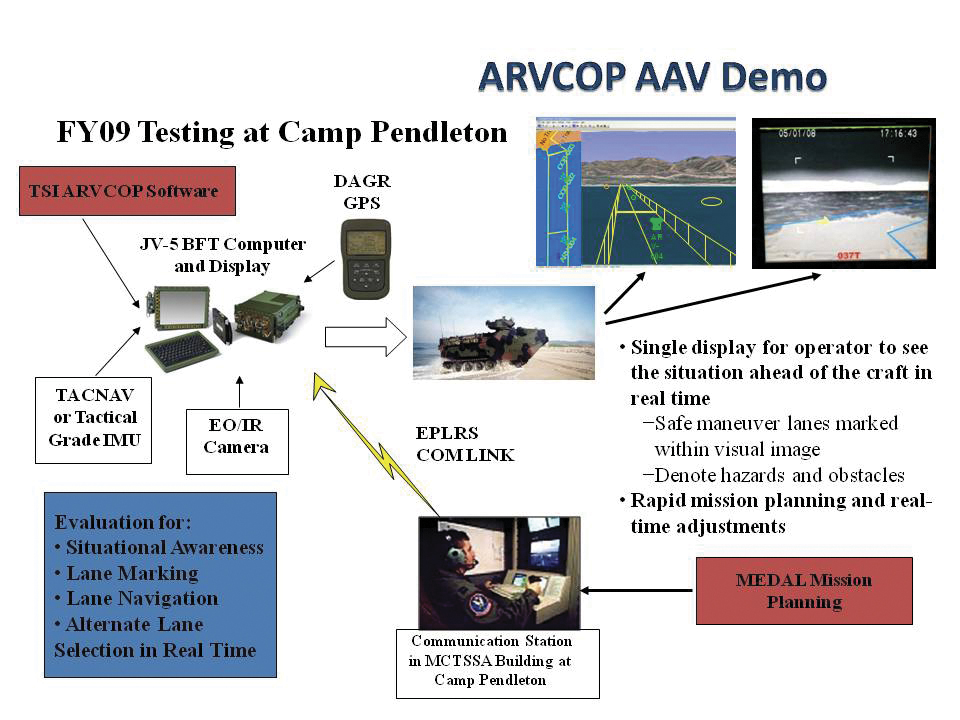
AR enables a rich suite of functions supporting the access and maintenance of a COP, and demonstrated maneuver accuracy. For the Augmented Reality Visualization for the Common Operational Picture (ARVCOP) system, any situational awareness information available can be overlaid on the real-world view in a clear and organized way. Operators do not have to go through the process of translating what they see on a map to what they see in front of them, a translation process that often incurs error. AR then delivers this to warfighters through a human-cognition friendly, integrated display of sensor data and geographically registered overlays, as Figure 1 illustrates. The AR view is shown along with a two-dimensional view on the right side of the display.
Figure 1. ARVCOP display example.
Developed by the Office of Naval Research with industry partner Technology Systems Inc., ARVCOP provides a human-machine interface that can magnify the effectiveness of precision positioning. In this article, we discuss how AR is utilized in this context and the results of testing AR precision-navigation systems aboard Marine Corps amphibious assault vehicles (AAVs, see photo) on the beaches of Marine Corps Base Camp Pendleton, California.
Precision piloting, or driving accuracy, is achieved by providing the operator a point toward which to drive that is in relation to the current position. Testing showed that looking ahead or driving to a point forced the operator to self-correct for the effects of wind, waves, and current.
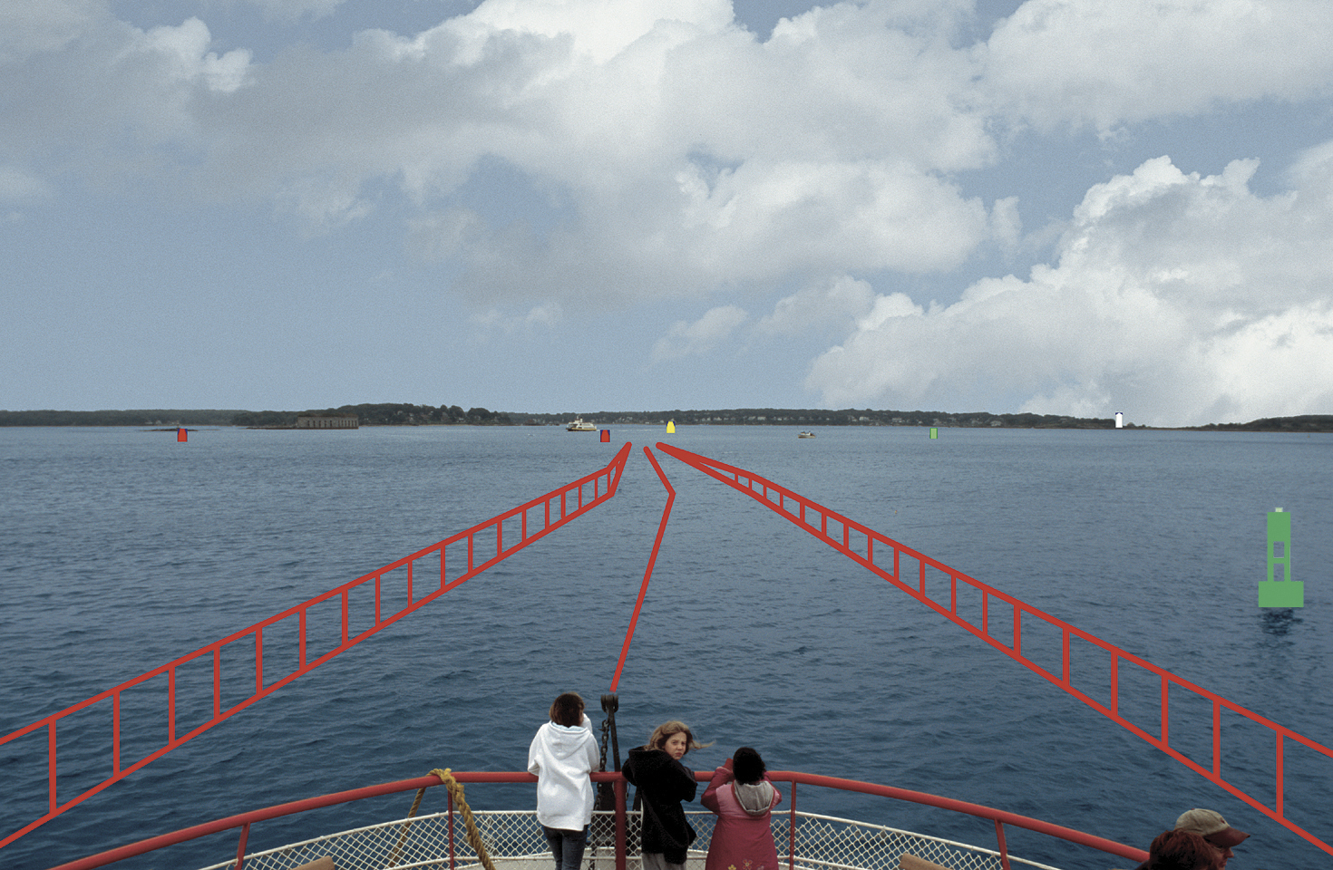
AR is exemplified by a software application that combines real-time video imagery with virtual images to provide a new dimension in navigation piloting accuracy. Figure 2 is an AR display on a ferry boat showing the navigational route marked by rails.
Figure 2. Real world with augmented reality.
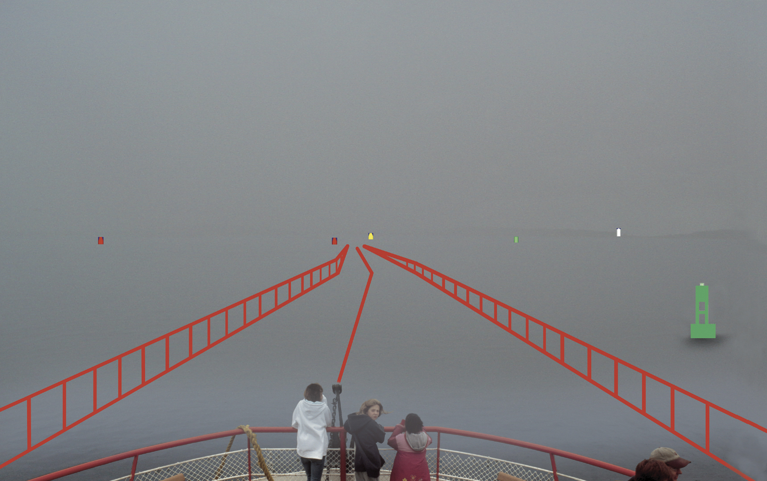
AR can overlay critical chart information such as buoys and channel markers, as well as radar or automated information system (AIS) contacts. In fact, any information that has a geo-registration component (geographic location attached) can be precisely overlaid on a real-time or infrared camera view. Operators have reported they are able to maneuver in unfamiliar waters at high speed with confidence, especially at night or in inclement weather (Figure 3).
Figure 3. Obscure visibility with augmented reality.
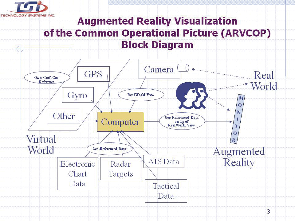
An operator using AR does not have to look down at a chart, radar, or AIS display, and then up at the real world to put the information into context. Charts, radar, and AIS output 2D information that must be made relevant to a 3D world. Analysis shows that converting 2D to 3D is a strenuous and error-prone task for the brain. Accidents can be caused by an initial mistake, which is then compounded by other decisions made with incorrect information. Figure 4 shows how AR automates the conversion process, allowing the human to focus on other relevant tasks.
Figure 4. Augmented Reality Visualization of the Common Operational Picture (ARVCOP) block diagram.
R & D Hardware
AR applications on AAVs have demonstrated the technology’s utility on land, in water, and through the hazardous surf zone, delivering precise routing through cleared transit lanes. The system is intuitive to operate. Operators with little or no training in AR systems executed precise maneuvers through lanes planned with bends and turns. The AR system used a military GPS and heading device. Electronic chart and tactical data brought positional context to the display. A virtual world was created and software algorithms draped the virtual world over a real-world camera view creating an AR display (Figure 5) for the AAV test.
Figure 5. AAV with research and development commercially available ARVCOP hardware.
Camp Pendleton Tests. In 2009, rigorous testing was completed for the ARVCOP system using AAVs in the surf at Marine Corps Base Camp Pendleton. Safe maneuver lanes were marked with mine-like objects and other hazards. Complex routes that included turns and zigzag patterns were planned toward the beach. Routes were delivered to vehicles using a radio circuit, and adjustments to the planned route were made on the fly to adapt to changing tactical situations.
The AAV is a 26-ton vehicle that is a challenge to operate when placed in a surface environment with wind, waves, and currents. Hardware employed ranged from legacy devices, including a magnetic heading device, to modern devices. With Research and Development (R&D) hardware, the results were dramatic compared to the traditional means of navigating assault lanes. The technology enabled new mission concepts, such as irregular routes ashore and avoidance of hazards sighted by other forces as the mission was in progress. The evaluation criteria for these tests were cross-track errors (CTEs), measured relative to a planned route. Separate, high-accuracy GPS was used for truth data to measure the accuracy of the route driven. Figure 6 shows the video camera and GPS antenna locations on the AAVs.
Figure 6. Video camera is located directly beneath the GPS antenna.
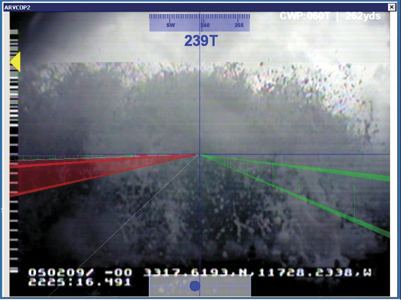
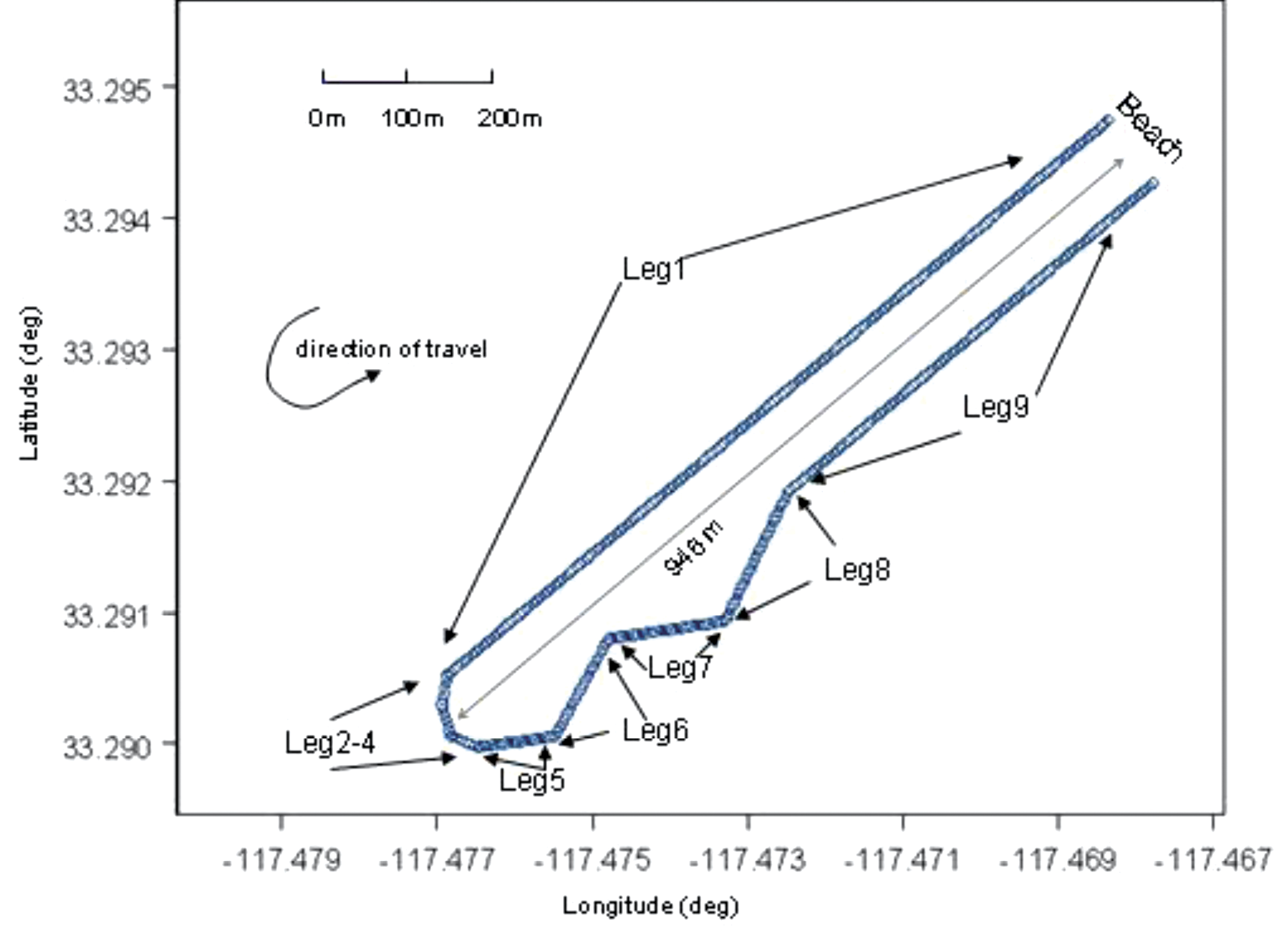
Figure 7 gives an example of the resultant AR video imagery for the R&D commercially available hardware on the AAVs. Figure 8 shows the planned routes for the R&D test evaluations. The distance offshore was 946 meters, and the planned total route length was 1,990 meters.
Figure 7. ARVCOP video using R&D hardware.Figure 8. Planned route for the R&D testing.
Video Augmentation Accuracy
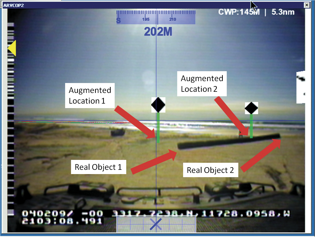
To determine position accuracy of the augmented figures drawn on the video images, time encoded images were captured. The augmented images were captured by ARVCOP using both the Civilian-Miniature Integrated GPS/INS Tactical System (C-MIGITS III) and the Tactical Navigation Digital Compass System (TACNAV) as input devices. Typically, multiple images are used to determine reference frame biases between the camera and the inertial measurement unit but, in this case, multiple image solutions lacked convergence. For this analysis, single-image solutions were generated. Figure 9, which shows locations of virtual and real objects, is an example of an image used in this analysis. The reference location of the virtual object is the bottom of the green post. The real-object coordinates input to ARVCOP were generated using a GPS survey and have centimeter-level accuracy. Figure 9 illustrates the inaccuracies in the system. During this calibration test, the augmentation showed errors of about 100 mrad (6 degrees) in the display of the virtual objects. (Authors’ note: This paragraph accurately reflects system performance on that day three years ago. Shortly after the test, system modifications were made that eliminated much of that error.)
Figure 9. ARVCOP image captured showing virtual and real objects.
Test Results
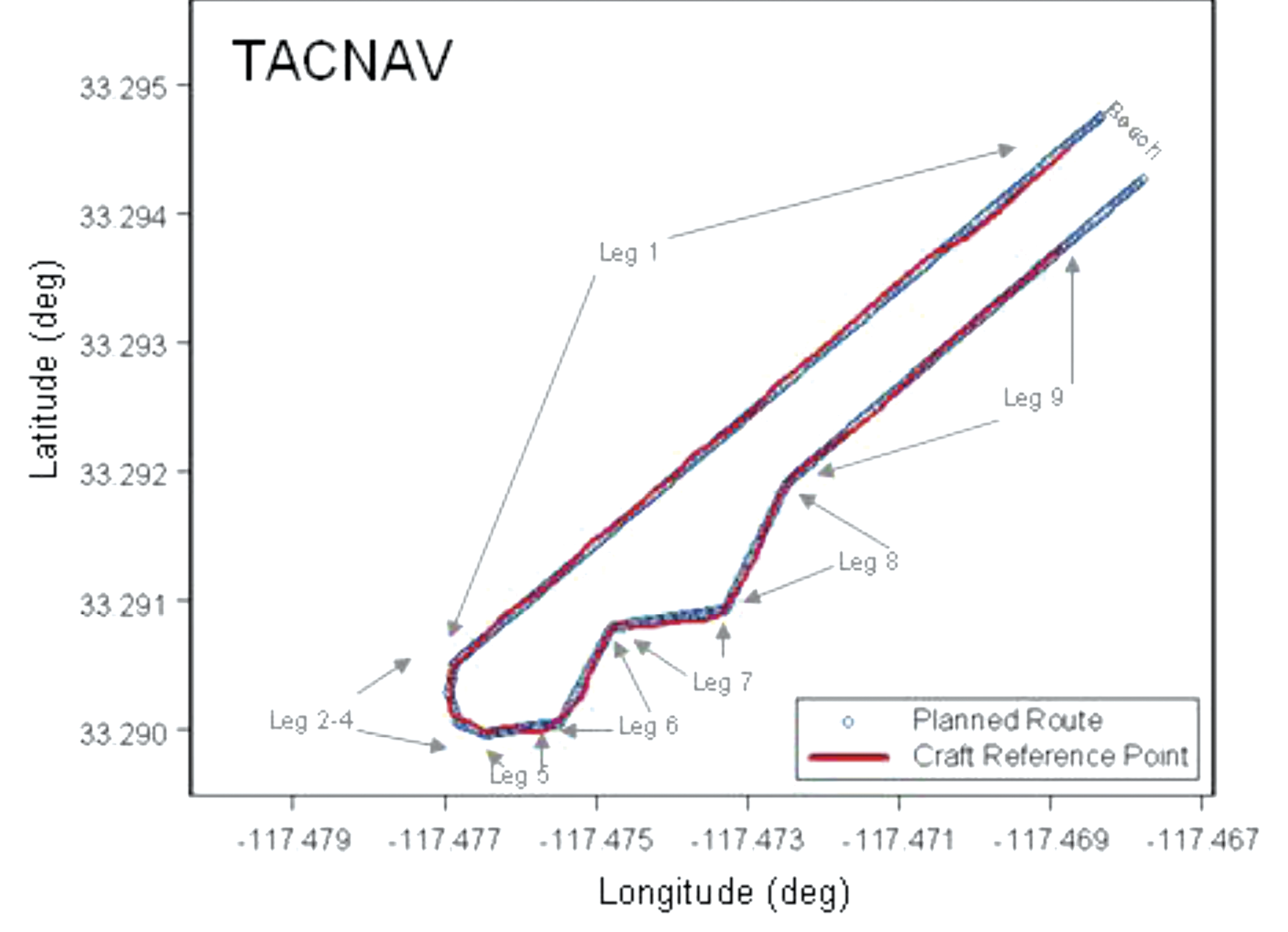
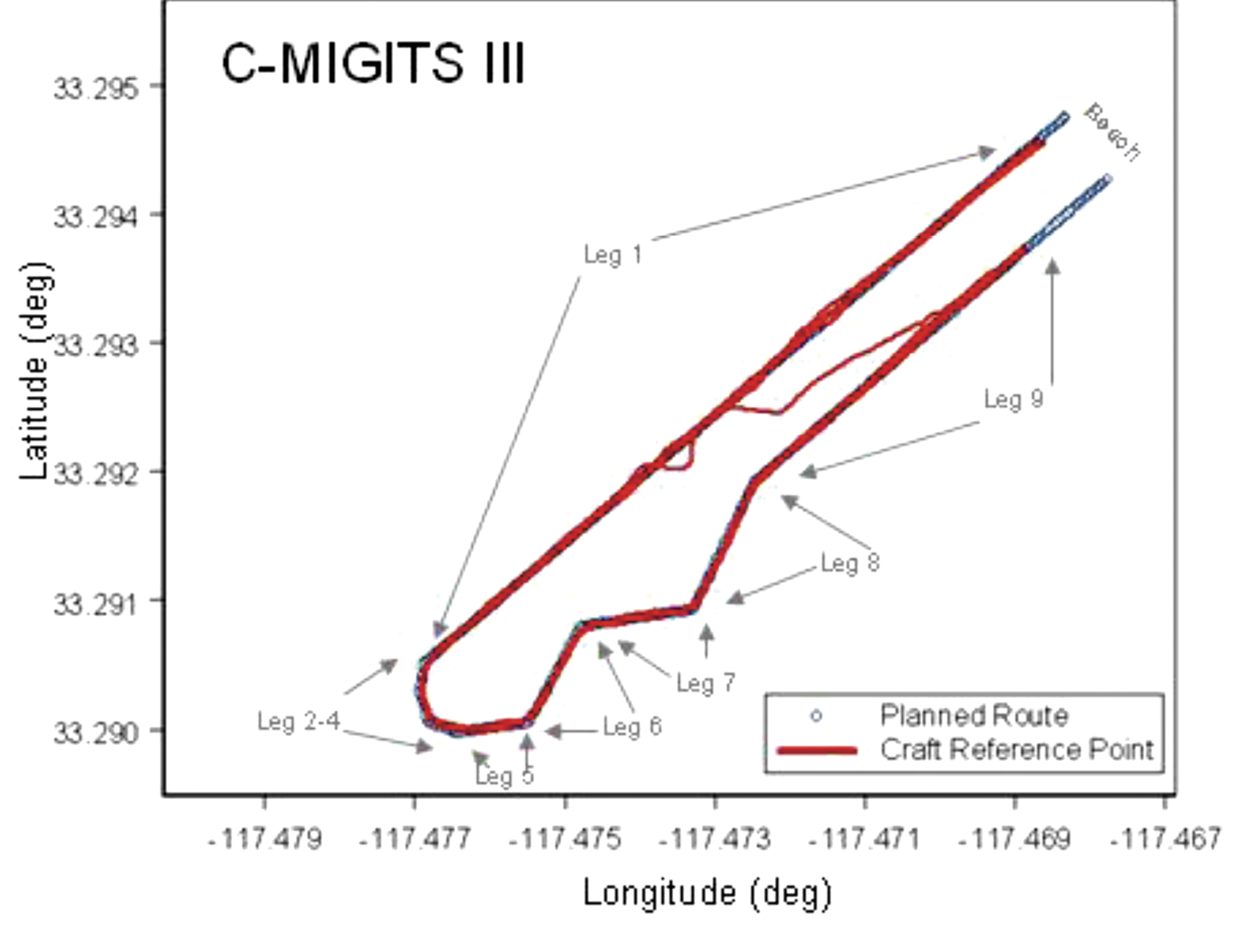
Evaluation of the AAV operation using ARVCOP as a driver’s aid was done by comparing the planned route with the actual route driven. The comparisons were made by finding the distance normal to the route, input to ARVCOP, and the vehicle’s estimated positions, generated using a GPS-relative positioning technique; no vehicle heading information was used and only horizontal components were compared. These differences between planned and executed routes are the CTEs. As mentioned earlier, both the C-MIGITS III and the TACNAV were used as input to ARVCOP for these tests. Figure 10 shows an example of the raw data, with the ARVCOP planned route (blue) overlaid with the GPS estimated positions (red). In this example, ARVCOP used C-MIGITS III heading input updated at a 10-Hz rate.
Figure 10 illustrates how the AAV stayed on the planned course, showing only small deviations. The blue line represents the planned route and the red points are the GPS-estimated positions.
Figure 10. AAV planned and actual route, Run 2.
When TACNAV was employed to supply heading information, similar results were seen. Figure 11 shows the first run made with TACNAV heading estimates. The AAV stayed on planned route except for some minor deviations.
Figure 11. AAV planned and actual route, Run 5.
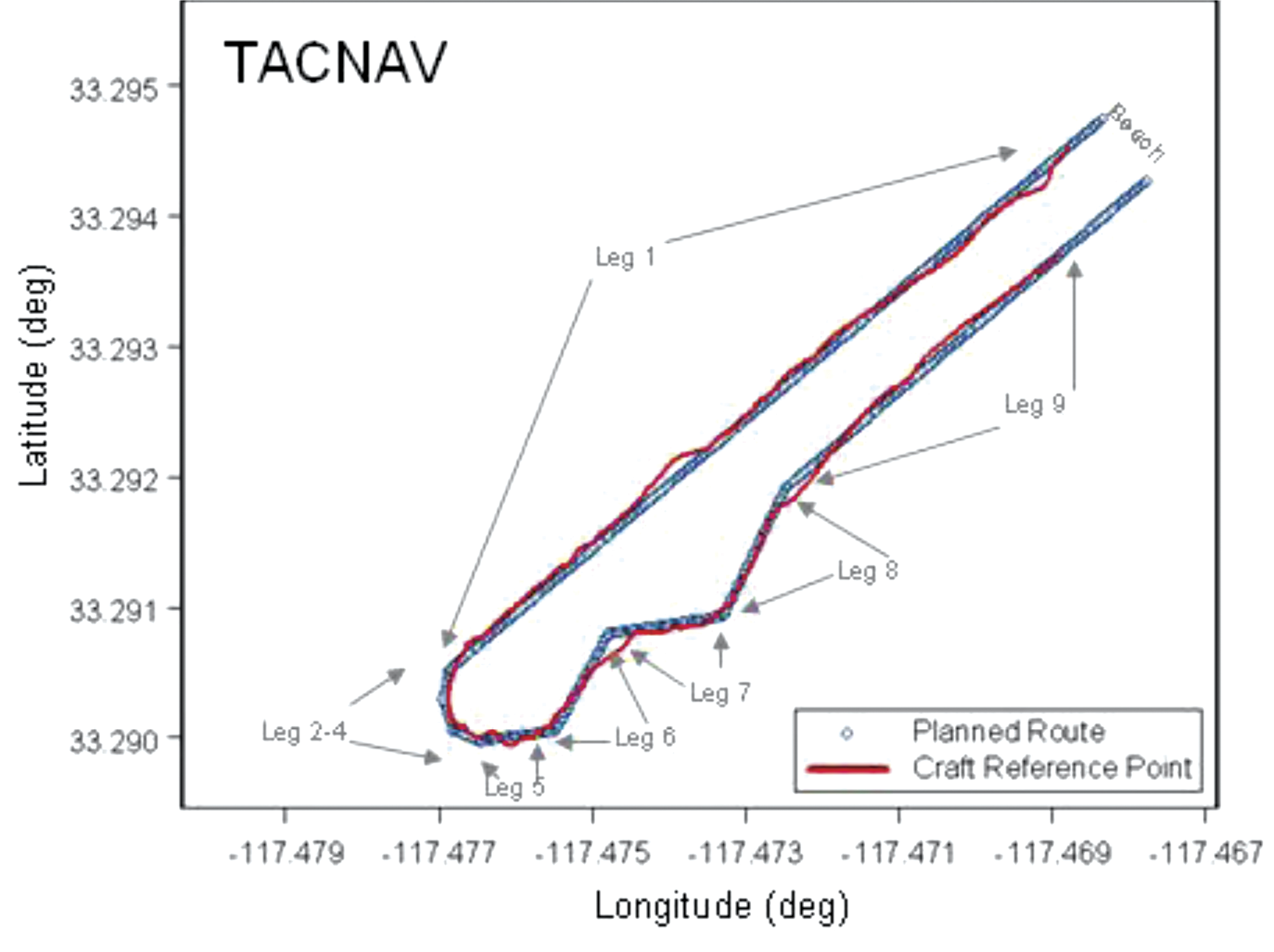
Figure 12 is of the second run using TACNAV heading information. In this instance, larger and more frequent excursions from the planned route are shown. The differences between Figures 11 and 12 are the result of the driver’s interpretation of the ARVCOP display. When the TACNAV was used as input to ARVCOP, the driver’s display showed greater instability than when the C-MIGITS III was used. The instability was a 1-Hz, few-degree shift in augmentation on the video corresponding to the TACNAV input rate. Figure 12 shows the result of the driver trying to follow all the augmentation shifts. When the driver ignored the sudden shifts in augmentation and drove a perceived average route, the resulting track was smoother, as Figure 11 shows. The 1-Hz input rate and the inherent TACNAV variations both contributed to the augmentation’s jumpy appearance.
Figure 12. AAV planned and actual route, Run 6.
Figure 13 shows the tracks of all the runs from the February 2009 tests that used the C-MIGITS III, except for runs 7 and 8. Run 7 was excluded because high surf caused its early termination when the vehicle was ordered to shore by the safety officer. The driver’s display was lost during Run 8 because of a loose cable and the test was aborted.
Figure 13. AAV planned and actual route, C-MIGITS-III heading data.Table 1 (left) shows the CTE statistics for the C-MIGITS–III runs. Table 2 (right) shows the CTE statistics for the TACNAV runs.
Table 1 shows the CTE statistics for the C-MIGITS–III runs. Table 2 shows the CTE statistics for the TACNAV runs. Average speed over the course varied from 4 to 5 knots. It took about 15 minutes to drive the entire route.
Discussion
Comparison of the heading estimates between the C-MIGITS III and the TACNAV estimates showed variations of about 3 to 5 degrees, after removal of a bias. Investigation of the relationship of the heading angle error with the heading angle showed that after TACNAV calibration, significant heading error correlations remained in its estimates. Using the TACNAV as a source of heading information showed that the slower 1-Hz update rate and inherent variations of the sensor degraded the augmentation software’s performance. For example, when using the TACNAV, the augmented lane boundaries occasionally jumped a few degrees corresponding to the receipt of heading estimate updates. This was particularly evident after vehicle turns. The C-MIGITS III 10-Hz update rate and higher accuracy estimates enabled ARVCOP augmentation without distracting artifacts and provided the driver with more accurate navigation information. The ARVCOP-augmented objects were drawn on the video with a heading accuracy of about 6 degrees.
During February 2009 R&D tests, the AAV made eight surf runs using ARVCOP with C-MIGITS III input and two runs using TACNAV input. CTE statistics for the ARVCOP C-MIGITS-III testing showed rms differences of about 2.9 meters. The ARVCOP TACNAV testing showed larger rms differences of about 4.9 meters. These statistics represent the rms error between the AAV’s planned and executed route.
Summary
AR technology provides a human-machine interface for a navigation system enabling precise maneuvering. ARVCOP presents navigation data so intuitively that operators are able to multitask as required in mission performance while still being able to precisely maneuver. ARVCOP proved the concept of AR-based precise navigation in rigorous operational scenarios with the U.S. Marine Corps (USMC).
Test results for the R&D commercially available civilian GPS/INS hardware provided CTE of mean 2.1 meters and standard deviation of 2.0 meters. Operational hardware was evaluated in July 2009 over four days of testing, including 47 runs, in conditions with sea states ranging between 1 and 2.5, and many drivers. In 2010, at NSWCDD and Naval Surface Warfare Center, Panama City Division (NSWCPC), land demonstrations were performed with similar hardware navigating cleared paths through simulated mine fields at night. Vehicles were able to transit cleared routes with no external markings. The Naval Sea Systems Command Program Manager, (PMS 495), Mine Warfare Office, is now installing ARVCOP on USMC AAVs.
Acknowledgments
This work was sponsored by Brian Almquist, program officer, Ocean Battlespace Sensing Science and Technology Department, Office of Naval Research. LtCol Brian Seiffert, USMC, acting director of the Amphibious Vehicle Test Branch (AVTB), Camp Pendleton, supported the demonstration. GySgt Chapa and SSgt Schaefer, USMC, coordinated the AVTB effort. Kennard Watson, NSWCPC, coordinated the Camp Pendleton test plan. William Chambers, Maritime Technology Consulting LLC, Udayan Bhapkar, Andrew Sutter, and Alan Evans, NSWCDD, supported the tests and evaluations. Ronald Paradis, KVH Industries, Inc., supported heading sensor calibration.
Manufacturers
The C-MIGITS III is made by Systron Donner Inertial Division (www.systron.com) and TACNAV by KVH Industries (www.kvh.com).
Tom Zysk (captain, U.S. Navy, retired) has more than 35 years of experience in the Department of Defense and industry. He held positions with Raytheon and General Dynamics before joining Technology Systems Inc.
Jeffory Luce is a senior program manager at Technology Systems, Inc. (TSI). As lead for the ARVCOP program, he successfully transitioned TSI’s first project to a Program of Record.
James Cunningham has worked in GPS research and development at the Naval Surface Warfare Center, Dahlgren Division, for more than 25 years
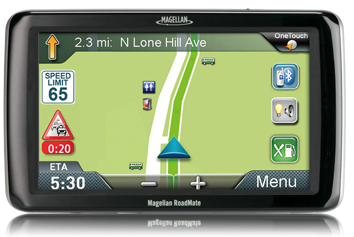
Magellan, maker of innovative GPS devices for vehicles, outdoor and mobile navigation, today announced the newest addition to its Magellan RoadMate Commercial GPS family for truckers and commercial drivers providing improved safety and productivity before, during and after their on-the-road trips. The compliance-ready Magellan RoadMate Commercial 9270T-LM GPS device is specifically designed for the needs of truckers including an extra-large GPS display, customizable truck-specific routing, hands-free communication, and trip logging.
To prepare for their trips, truck drivers can use the Magellan RoadMate Commercial 9270T-LM to set up customizable routes based on the height, weight, width, and length of the vehicle, as well as applicable hazmat restrictions. Multi-destination routing allows drivers to plan their stops and optimize routes to help them save time and gas, Magellan said.
While on-the-road, the Magellan RoadMate Commercial 9270T-LM helps drivers navigate on an extra-wide 7-inch high-definition touchscreen display that adjusts color and contrast for easy night-viewing. The large display also makes maps and other content easy to read when the GPS Navigator is mounted in large vehicles with deep dashboards. The integrated Bluetooth wireless technology, when paired with a compatible Bluetooth phone, enables drivers to safely talk hands-free while keeping their eyes on the road.
At the end of their trip, the Magellan RoadMate Commercial 9270T-LM facilitates preparing required compliance reports including hours and state mileage for IFTA fuel records. A comprehensive log of trip information by each driver is retained in the Magellan GPS device for easy exporting into reports.
“We expanded our family of Magellan RoadMate Commercial GPS Navigators to further meet the unique navigation needs of commercial and truck drivers who need a comprehensive solution to efficiently perform their jobs from the initial trip planning stage to their on-the-road requirements and managing required log reporting after their trip,” said Stig Pedersen, Associate Vice President of Product Management for Magellan. “The Magellan RoadMate Commercial series of GPS Navigators are designed to make drivers’ jobs safer and less stressful plus improve productivity, reduce costs and ultimately increase profits.”
The Magellan RoadMate Commercial 9270T-LM functions as an “information dashboard” that not only navigates, but provides elevation and truck speed limit warnings. The 9270T-LM GPS device includes several valuable safety and convenience features:
Highway Lane Assist that shows realistic highway signs and guides truck drivers towards the correct lane when approaching complex highway interchanges and exits;
Free Lifetime Traffic Alerts that help drivers avoid traffic incidents on their route by offering an alternative solution;
Spoken Street Name guidance that announces the street name and gives turn-by-turn directions;
Highway Exit Points-of-Interest and a Truck Stop Directory help drivers find services including gas stations, restaurants, ATMs, rest areas and showers, truck services, Wi-Fi availability;
OneTouch lets truckers bookmark and assign a button to their favorite destinations or searches for faster access;
Heavy-duty extended windshield mount, designed for deep dashboards, is included to provide fully-adjustable, personalized comfort and safe viewing;
An A/V input for easy connection to external devices such as the Magellan Wireless Back-up Camera or a DVD player;
Free downloadable Lifetime Map Updates keep the pre-loaded maps of the United States, Canada and Puerto Rico up-to-date.
The Magellan RoadMate Commercial GPS family now includes two models — the new 7-inch Magellan RoadMate Commercial 9270T-LM ($399.99 MSRP) and the 5-inch Magellan RoadMate Commercial 5190T ($379.99 MSRP). Both models are available in June at truck stops and through Magellan’s consumer electronics and online partners.
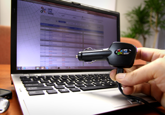
Digital Matter Embedded, a South African based provider of innovative technology providing electronic and software solutions for a wide range of Industry applications, has launched a compact GPS logging device which plugs into any vehicle’s cigarette lighter. The device, the GPS Log Book, is designed around u-blox’ NEO GPS receiver module to provide an easy way for drivers to automatically keep an accurate travel log book which can be securely accessed later from anywhere via a web interface. Information logged includes route, speed, and distance traveled. The device is targeted at businesses where tracking of vehicle usage is an important part of their cost control and accounting: taxi, emergency, and delivery services, as well as for traveling sales personnel.
“The GPS Log Book takes advantage of u-blox’ extremely sensitive GPS receiver technology to provide a simple and useful way to keep an accurate overview of vehicle usage,” said Alex Soldatos, general manager at Digital Matter Embedded. “The GPS Logbook provides a simple, cost-effective way for businesses to keep track of one of their most valuable assets: their cars.”
“The GPS Log Book takes full advantage of u-blox’ leading positioning technology: it requires fast satellite acquisition and re-acquisition speeds, small module size, and high sensitivity to allow the use of a very small GPS antenna,“ said Huub Robroek, regional sales manager at u-blox. “Basing their design on our NEO GPS module has resulted in an impressive, compact device that delivers useful and reliable vehicle usage data.”
The GPS Log Book uploads its log data on both PC or Mac via USB where a web interface application allows users to manage their devices, view trips, and add locations as well as many other useful functions including creating powerful, informative reports. Most notably, the log book can be generated for use with income tax return for individuals. Data is stored for more than five years and can be viewed at any time if required.
The European GNSS Agency (GSA) has published its second Global Satellite Navigation System (GNSS) Market Report, providing key information to entrepreneurs in the satellite navigation sector.
GNSS market forecasting is of great interest to private and public GNSS stakeholders, for business and strategic planning and policymaking, according to the GSA. According to the 2012 GSA Market Monitoring Report, the worldwide GNSS market is growing fast and the total market size is expected to increase at an average of 13 percent per year until 2016.
The total enabled GNSS market size is expected to stabilise in the latter half of the decade due to market saturation, price erosion and platform convergence. Global shipments of GNSS devices are lower than previously forecasted up until 2015 yet are forecasted to continue growing to over 1.1 billion units per year.
Expanding coverage. Following up on the first GNSS Market Report published in 2010, the GSA’s 2012 Report includes an analysis of two new sectors: maritime and surveying. Relevant examples from EU research projects have also been included for each sector.
2012 Report Highlights
Road and location-based services (LBS) still in the lead. Road and LBS dominate GNSS device sales (54% and 44% respectively). LBS constitutes 87% of the total GNSS market in terms of units sold and GNSS penetration in smartphones is set to increase from 30% today to almost 100% in 2020. For road navigation, traditional Personal Navigation Devices (PNDs) will gradually disappear from the European market yet remain present in other regions in the form of low cost OEM products. Smartphones and in-vehicle devices will be the preferred means of navigation.
Commercial aviation use will grow. In the Aviation sector, the segment that will see the greatest growth in terms of GNSS equipment revenues will be Commercial Aviation, surpassing general and business aviation by 2018.
GNSS use in agriculture continues to rise. In agriculture the current positive growth trend will continue; low cost precision agriculture solutions based on EGNOS are driving GNSS adoption by farmers in Europe.
Surveying: a growing opportunity. In surveying, the construction segment is dominating the market in terms of units and value. North America is leading in terms of market penetration but the other regions will catch up by 2020 as GNSS is rapidly replacing the traditional surveying and mapping methods in Europe and around the world.
Safer seas with GNSS. In the open sea segment, shipments of search-and-rescue (SAR) beacons will exceed those of other categories making the SAR segment the largest in terms of shipments and second largest in terms of market size.
NovAtel Inc. today announced the development of its OEM625S Selective Availability Anti-Spoofing Module (SAASM) GNSS receiver, a collaborative effort between NovAtel and L-3 Interstate Electronics Corporation (IEC).
System integrators have come to rely on the centimeter-level positioning accuracy made possible with real-time kinematic (RTK) commercial GPS receivers. Many authorized defense customers rely on access to the Precise Positioning Service (PPS) for single-point positioning. The OEM625S will combine a commercial dual-frequency NovAtel GNSS receiver with an L-3 IEC XFACTOR SAASM in a single card solution, reducing overall size and power requirements for end customer applications.
The OEM625S will maintain NovAtel’s OEMV-2 form factor, ensuring a successful drop-in replacement and backward compatibility for existing customers. Integrators can continue to use their existing user interface, which will be enhanced with OEM625S logs and commands for SAASM functionality.
NovAtel’s well-established, comprehensive set of software commands facilitates system integration, NovAtel said. The SAASM position is provided via a dedicated communication port, as well as through NovAtel’s software command protocol, allowing for maximum flexibility.
“For the past 17 years NovAtel’s customers have enjoyed great success in integrating our OEM family of high-precision receivers into a wide array of defense applications,” stated Graham Purves, executive vice president of NovAtel. “Adding the L-3 XFACTOR SAASM to our receiver card will allow defense customers to continue to use our products in the most demanding military environments.”
Ric Pozo, general manager of L-3 IEC’s Navigation Systems business unit, commented, “We are pleased to collaborate with NovAtel and provide the warfighter this highly flexible and capable GPS SAASM product. Our combined teams are looking forward to bringing this one-of-a-kind solution to market.”
NovAtel will accept orders for the OEM625S from authorized customers starting in the third quarter of 2012.
I received a bit of email from my article last week on open source GIS. There are two letters from readers I’d like to share with you because I think they clearly represent two different perspectives of the open source GIS discussion.
I’d love to hear from more folks about their open source GIS apps. Please send me a quick email.
The first letter points out an important fact about open source GIS that I didn’t touch on last week. His point is that with open source GIS, anyone can modify the software source code to add or change features of the software.
Dear Eric,
I’ve been following your writings for a few years now, and I’m delighted to see you bring up open source geospatial software in your column!
Last year, I finished an online MGIS degree from Penn State, using open source GIS and web mapping tools with local township staff for my “capstone project.” Here in Michigan, townships are the local units of government that are below counties in the hierarchy of governments. There are over 1200 of them in the state.
Open source tools, I think, represent an “enabling” technology and movement, especially for impoverished township governments like those I worked with in northern Michigan. There, some of the staff may actually be trained in using commercial GIS tools (from previous employment or from schools), but their small, rural townships may not be able to afford licenses for them. In other townships, staff have enthusiasm for, but not training in, GIS tools, and are willing to spend the time to learn and use them if their townships can provide them with such tools. (Here again, up here in rural northwest lower Michigan, townships typically can’t.) The townships up here typically have populations in the low thousands.
For this segment of potential users, open source desktop GIS tools such as QGIS and uDig turned out to be just what was needed. For a couple of townships, I just had to show them how to download and install these tools, and then they were off on their own! After they created paper maps and such for their use (planning commission work, recreational planning, and so on), I made online interactive versions for their websites using open source tools. Such open source web mapping tools included Open Layers, Geoserver, and even Google Maps API, even though Google Maps API is not, strictly speaking, open source. In other townships, I initially had to sit down and coach them in the use of QGIS and uDig, but they soon caught on and started producing their own mapping products. Granted, the maps were fairly simple maps, but perfectly adequate to communicate to their constituents whatever needed to be communicated. Without open source GIS products, none of this would have been possible, especially in today’s economic climate.
If you take a close look at QGIS, for example, you’ll see that the current release version (1.7.4) and the development version (1.9.x) contain highly sophisticated tools that rival those from commercial packages. In fact, for the vast majority of potential users (such as those I worked with), what are in the current versions are more than enough for their needs. Through the efforts of the worldwide communities of enthusiastic, part-time developers who program in their own time, these open source geospatial products of great sophistication are made available to those who need them most!
Again, thank you for hi-lighting open source geospatial products in your column!
Howard Yamaguchi
P.S. Eric, in your column you dwelled on the “free as in free beer” aspect of open source, where anybody can download the software and use it, gratis. The other aspect of open source that you could have mentioned is the part where, in addition to downloading the product, we can also download the source code and tinker with it. We are then free to use the tinkered code for our own use, even to profit from it by deploying and using such modified versions for our clients. Open source licenses typically require us to eventually upload the modified source code to the developer community so that they can, if they so choose, incorporate it into the release versions of the product. That’s the “free as in free speech” part, the part that really distinguishes open source software from the world of commercial software. (But you probably knew all this!) Cheers!
Following is a letter from a gentleman who says the cost-savings potential with open source GIS isn’t worth it for the organization he works in.
Eric—
Thanks for your always insightful columns. You asked for feedback from users who are using open source GIS apps, but might I offer the following counterpoint? The electric utility company I work for doesn’t use open source GIS and has no plans to use it, regardless of how reliable or low-priced it becomes. “Why?” you ask. “Is it because we’re herd-bound and lacking vision? Are we so tied to our big-box traditions that we can’t see the coming GIS software wave?”
No, the reason is simply that the cost of neither software nor hardware is significant in comparison to the value of GIS data integration. When our system operators remotely close a switch, the distribution SCADA system’s electrical-connectivity data (which it receives from our GIS) darn well better correctly identify the facilities it just energized. So a GIS that’s highly integrated into our distribution-SCADA, accounting, work-management, outage-management and meter-data-management systems is a bargain at any price; but a stand-alone GIS app (even one with really great data-collection capabilities) is effectively worthless to us, regardless of how cheap it is.
This system integration is not something our management cares to do in-house (though I’m always making the argument that we can and should do more in-house), nor is it something we can entrust to volunteer hackers (regardless of how altruistic they are). There will always be a market for high-dollar GIS platforms that frictionlessly exchange real-time data with mission-critical systems.
It seems (to me anyway) that the only role open source apps might play is in areas that don’t involve interfaces with other mission-critical systems — e.g., in presenting our GIS data alongside other datasets, or perhaps in data collection/validation.
Thanks again, for your always interesting insights,
If you recall, one of the trends identified by the experts that the United Nations polled was that “There is unlikely to be a market for datasets like those currently sold to power navigation and location-based services solutions in five years, as they will have been superseded by crowdsourced datasets from OpenStreetMaps or other comparable initiatives.”
Do you think that Bob’s rationale also applies to open source data? I’m sure that’s what Navteq/Nokia and Teletlas/TomTom would argue.
Personally, I think that the U.N. prediction of five years is pretty aggressive. Navteq and TeleAtlas have put a tremendous amount of time and effort into collecting and validating their datasets. They get paid to be accountable for the quality of their product. The challenge for OpenStreetMap to take over the GPS Personal Navigation and other LBS markets is that the quality bar has already been set. If OpenStreetMap data quality doesn’t match or come close, the user experience will be disappointing and OpenStreetMap’s reputation will take a hit.
Don’t take this wrong, though. Open source GIS data sources like OpenStreetMap, OpenSeaMap, etc. have a bright future. As I’ve written before, and as the U.N. correctly identifies, the proliferation of high-precision GNSS receivers, along with other sensors, will make high-precision data collection inexpensive and commonplace. Super-detailed, feature-rich, open source data is in our future.
Eric Gakstatter, GPS World’s contributing editor for Survey/GIS, will speak at the 2012 Esri International User Conference, which will be held July 23-27 in San Diego, California.
In his “GPS/GNSS Technology Update,” Gakstatter will provide a discussion on how current and upcoming satellite systems affect the user. The talk will be held in Room 31B at 10:15-11:30 a.m. on Thursday, July 26. Here is the official description:
ArcGIS Mobile users around the world are challenged to keep current with evolving satellite systems. There are new GPS satellites being launched with new GPS signals being broadcast (L5). The Russian GLONASS system is near operational and Europe has launched its first two Galileo satellites. Not only are the satellite systems changing but also GPS augmentation systems such as WAAS, DGPS, EGNOS, MSAS and GAGAN systems. ArcGIS Mobile users take advantage of these GPS/GNSS augmentation systems and should be aware of how they are evolving. The LightSquared controversy is still a major threat to GPS/GNSS users. How might that affect the future of GPS/GNSS mapping/surveying? How do these changes affect spatial data collection and navigation services within ArcGIS Mobile? Which factors should one consider when using these different satellite systems. What are the current trends and developments that one should consider when preparing GPS/GNSS mapping hardware budgets?
To learn more about the conference, read about it in our Events section here.
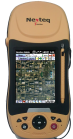
Nexteq Navigation, based in Calgary, Alberta, Canada, has announced the T5A, its new flagship multifunctional GNSS handheld data collector. The device is a high-accuracy GPS unit capable of 2-centimeter accuracy using real-time kinematic (RTK) and 50-centimeters globally using Nexteq’s i-PPP technology. With the T5A, users can achieve extremely accurate and consistent results anywhere in the world with no loss in flexibility, Nexteq said, adding that the unit’s centimeter-level precision coupled with versatility allows for accurate data collection in the most diverse weather conditions.
Suitable for projects in all-environments, the T5A has a professional quality internal GPS receiver that provides accurate real-time results. Using Nexteq’s Freedom, i-PPP, or RTK technologies, the T5A data collector can provide flexible and accurate positioning in all parts of the world, Nexteq Navigation said.
The T5A has a 3.7-inch color touchscreen that is both waterproof and dustproof. The device includes features such as Bluetooth, Wi-Fi, digital cellular data and voice, microSD card slots, and a 3.0 megapixel digital camera.
Like all Nexteq Navigation GPS handhelds, the T5A is a ruggedized and tough unit. The T5A has an IP66 rating with excellent dust and water resistance.
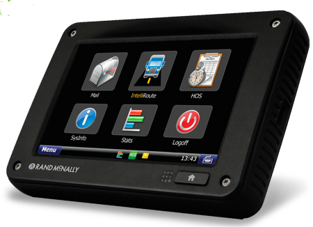
Rand McNally has announced a new pricing plan, new features, and a new warranty program for its single-box compliance solution for fleets. The TND 760 Fleet Edition is a next-generation in-cab electronic on-board recorder (EOBR) device that installs in less than 30 minutes, is low cost, and is easily adopted by drivers, the company said.
For as little as $649 for the hardware, and $19.95 per month for service, trucks can be equipped with a fully compliant EOBR solution. For $799, the device also comes loaded with Rand McNally’s navigation. Lease options are available for as low as $39 per month for qualifying fleets.
Among the new items announced today, three monthly service plan options are now available. The EOBR plan, offering electronic hours of service and vehicle inspection reporting, for $19.95/month; the Basic plan, which layers on vehicle positioning and online mapping, text and form messages, driver email and attachments, as well as integration access via Rand McNally Connect, for $29.95; and the full Enterprise plan that layers on a driver scorecard, vehicle performance, critical event reporting and vehicle maintenance, for $39.95. These service plan prices are based on a three-year commitment.
A three-year warranty is now standard on the TND 760 hardware, providing customers peace of mind for the term of the agreement that their hardware is covered under warranty. This is an upgrade from the standard one-year warranty typically offered in the industry.
And, Rand McNally announced a group of new features coming on stream in the next few months. By the end of June, a new back-end mapping portal with upgraded geofencing, alerting, and route replay will be up and running. This feature will be part of the Basic and Enterprise monthly plans. Also in development are significant enhancements to the IntelliRoute TND GPS navigation software, including the ability for fleets to send, and for drivers to receive, routes on the TND 760.
“As we roll out the TND 760 to more fleets and transportation companies, we’re finding that there are a number of items they’re responding to,” said Dave Muscatel, CEO of Rand McNally. “The low cost, the quick installation, and the fact that Rand McNally is well regarded among professional drivers is key. When drivers accept the device, they use it.”
The Rand McNally TND 760, Fleet Edition, first available Q4 of 2011, integrates with a truck’s on-board computer and sends and receives information via both Wi-Fi and cellular modes. The TND 760, manufactured in the U.S.A., is designed to be set up in less than 30 minutes and does not require the installation of a separate “black box” monitoring unit like traditional mobile communication systems.
Despite its compact design, the TND 760 features a broad array of capabilities including fleet communications via email, driver and vehicle performance monitoring, electronic hours of service (HOS) compliance, and truck-specific navigation. Information on fleet activity is managed via Rand McNally’s significantly enhanced FleetWatcher web-based portal.
For more information and product demonstrations, potential customers should call 1-800-641-RAND (7263) or go to randmcnally.com/tnd760.
Hexagon AB announced it has acquired all shares in the Norwegian company My Virtual Reality Software AS (myVR).
According to the announcement, myVR provides software that offers a solution for 2D, 3D and 360-degree viewing for desktop and mobile. The company has developed a patented technology platform that enables high-resolution real-time viewing of interactive maps over networks with limited bandwidth. The platform makes it possible to view large-scale models on any 3D hardware-supported client platform, including mobile phones and tablets.
myVR 3D Map
"The acquisition of myVR will be of great value for Hexagon's current offerings. Everything is going mobile, including our customer offerings," said Ola Rollén, President and CEO, Hexagon AB. "In the past, the problem with displaying 3D data on a mobile device such as a tablet has been size limitations of data transfers, and also the ability to handle the transfer in a real-time environment. myVR has a unique solution to this problem, and Hexagon will make use of its technology in all of our divisions."
Founded in 2003, myVR provides real-time, 3D virtual technology to the Oil & Gas, Building & Construction, Government and Web Portals industries, as well as other traditional and emerging digital markets.
Hexagon announced that myVR will be fully consolidated as of today. The acquisition will not have any visible impact on Hexagon's earnings in the short-term.
Several new rugged GPS-enabled devices were announced this week.
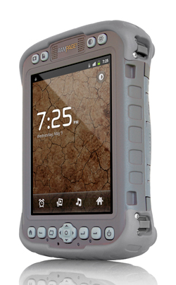
Juniper Systems has partnered with Pennsylvania-based SDG Systems to market the Mesa Rugged Notepad with Android (AOSP) 2.3 operating system, a rugged handheld computer known as the RAMPAGE 6 and distributed through SDG Systems. Availability of the RAMPAGE 6 is scheduled for the third quarter of 2012 and its first public presentation will be at the Esri International User Conference in San Diego, July 23–27, 2012.
The Android (AOSP) 2.3 operating system on the RAMPAGE 6 offers many advantages for data collection, including easy multi-tasking, a modern user interface, rich programming environment, multi-platform development, abundant application data storage, open source flexibility, and the opportunity for a custom Android interface developed by SDG Systems, according to Juniper Systems. Additionally, its optional kiosk mode allows only certain applications to be accessible by the user, creating a single-purpose device without distractions, Juniper Systems said.
The RAMPAGE 6 will have the same features as the Mesa Rugged Notepad, including a large 5.7-inch viewing display, IP67 ingress protection rating for water and dust, integrated 2–5 meter GPS receiver, optional integration of a 1D/2D barcode scanner, and optional Class I, Division 2 certification for use in hazardous locations.
Meanwhile, DRS Technologies, Inc., announced today that its Tactical Systems division has expanded its product portfolio with three new ARMOR rugged tablets. The ARMOR X7et and the ARMOR X7ad are thin, lightweight tablets based on customers requesting even more portable computers from ARMOR, the company said. “The 7-inch multi-touch tablets shatter the perception of bulky, rugged computing, and offer field service workforces the ability to choose between the fast-growing Android OS and the enterprise-friendly Microsoft Windows platform,” The company said. Additionally, DRS is now offering a new light convertible tablet, the ARMOR X12kb, that meets MIL-STD-810G. All three follow introduction of the ARMOR X7 compact rugged tablet launched in 2011.
The ARMOR X7et is a Windows-based tablet that weighs less than 1.5 pounds and provides six hours of battery life. It features an Intel Atom Z670 processor and runs Microsoft Windows 7 Professional. Its Android counterpart, the ARMOR X7ad, weighs 1.3 pounds and operates for up to eight hours. It features a NVIDIA Tegra 2, 1.0-Ghz dual-core processor, and operates on Android v3.2. Both lightweight tablets feature a 7-inch outdoor-readable multi-touch screen display. They are certified to MIL-STD 810G for extremes in temperature, vibration, shock, and four-foot drops and have an IP65 rating for ingress protection, which means they are fully protected against dust and can withstand low pressure jets of water from all directions.
Weighing 5.5 pounds, the ARMOR X12kb features a 12.1-inch sunlight-readable swivel touchscreen that incorporates polarized LCD glass and anti-reflective technology. The ARMOR X12kb offers the Intel Core i5-560UMCPU processor and runs Microsoft Windows 7 Professional. It has a long battery life, operating for up to eight hours, as well as a spill-proof keyboard and touchpad. Additionally, the one-click stealth mode operation disables all emitting light and sounds, a feature designed for the unique applications of covert operations.
The three new ARMOR mobile computers include connectivity options including Gobi Wireless Broadband, integrated GPS, 802.11 b/g/n Wi-Fi, and Bluetooth wireless. They are designed to make it easier for workers to use mobile computing in rugged environments, as this product video shows: